Review

Vision-Based Navigation Techniques for Unmanned Aerial Vehicles: Review and Challenges

by
Muhammad Yeasir Arafat
,
Muhammad Morshed Alam
and
Sangman Moh
*
Department of Computer Engineering, Chosun University, 309 Pilmun-daero, Dong-gu, Gwangju 61452, Republic of Korea
*
Author to whom correspondence should be addressed.
Drones 2023, 7(2), 89; https://doi.org/10.3390/drones7020089
Submission received: 16 December 2022 / Revised: 20 January 2023 / Accepted: 25 January 2023 / Published: 27 January 2023
(This article belongs to the Special Issue Recent Advances in UAV Navigation)

Abstract

:
In recent years, unmanned aerial vehicles (UAVs), commonly known as drones, have gained increasing interest in both academia and industries. The evolution of UAV technologies, such as artificial intelligence, component miniaturization, and computer vision, has decreased their cost and increased availability for diverse applications and services. Remarkably, the integration of computer vision with UAVs provides cutting-edge technology for visual navigation, localization, and obstacle avoidance, making them capable of autonomous operations. However, their limited capacity for autonomous navigation makes them unsuitable for global positioning system (GPS)-blind environments. Recently, vision-based approaches that use cheaper and more flexible visual sensors have shown considerable advantages in UAV navigation owing to the rapid development of computer vision. Visual localization and mapping, obstacle avoidance, and path planning are essential components of visual navigation. The goal of this study was to provide a comprehensive review of vision-based UAV navigation techniques. Existing techniques have been categorized and extensively reviewed with regard to their capabilities and characteristics. Then, they are qualitatively compared in terms of various aspects. We have also discussed open issues and research challenges in the design and implementation of vision-based navigation techniques for UAVs.

1. Introduction

Owing to the rapid deployment of network technologies, such as radio communication interfaces, sensors, device miniaturization, global positioning systems (GPSs), and computer vision techniques, unmanned aerial vehicles (UAVs) have become a potential application in the domain of military and civil society [1]. UAVs have been utilized in many civil applications, such as aerial surveillance, parcel delivery, precision agriculture, intelligent transportation, search and rescue operations, post-disaster operations, wildfire management, remote sensing, and traffic monitoring [2]. Recently, the UAV application domain has increased significantly owing to its cost effectiveness, fast mobility, and easy deployment [3].
UAVs are classified based on their characteristics [4], such as size, payload, coverage range, battery lifetime, altitude, and flying principle, as listed in Table 1. Compared to high-altitude UAVs, low-altitude UAVs have smaller battery capacity and fewer computing resources due to their size constraints. Several high-altitude UAVs have energy management capabilities, including wireless charging stations and small solar panels mounted on the aircraft. In general, UAVs are categorized based on their physical structures, such as fixed and rotary wings. Fixed-wing UAVs are widely used in military applications, such as aerial attacks and air cover. They have high-speed motion, high payload capacity, and long-lasting battery backups; however, most fixed-wing UAVs do not have vertical takeoff and landing (VTOL) facilities [5]. Recently, rotary-wing UAVs have been widely used in various civilian applications owing to their physical characteristics, such as supporting stationary positions during flight and VTOL facilities. Without human assistance, UAVs and aircraft exhibit high mobility and flexibility for civilian emergency applications [6]. However, UAVs cannot handle top-level communication and perception in a complex environment using traditional sensors. As a result, they still have to overcome challenges, such as object detection and recognition, to avoid obstacles toward achieving desirable communication [7]. Therefore, researchers have focused on the development of high-performance autonomous navigation systems.
In recent years, several approaches aided by vision-based systems have been developed for UAV navigation. The UAV flies successfully when it avoids obstacles and minimizes path length. Navigation involves three main processes: localization, mapping, and path planning [8]. The localization is initially determined. A map is then visually constructed to refine the search process and avoid obstacles, in addition to allocating suitable landing sites. Eventually, the planning process aims at determining the shortest path using a proper optimization algorithm. There are three main categories of navigation methods: inertial, satellite, and vision-based navigation. Vision-based navigation using visual sensors provides online information in a dynamic environment because of their high applicability of perception owing to their remarkable anti-inference ability [9]. Exteroceptive and proprioceptive sensors are used for navigation. The dataset is then preprocessed internally for localization and mapping, obstacle avoidance, and path planning, and finally, outputs to drive the UAVs to the target location are provided. Several traditional sensors, such as GPS, axis acceleration, gyroscope, and internal navigation system (INS), are used for navigation [10]. These sensors are not as accurate as their performance accuracy. For example, reliability is a significant drawback of GPS, and its location accuracy is positively correlated with the number of available satellites [11]. However, INSs suffer a loss of accuracy owing to the propagation of the bias error caused by the integral drift problem.
Meanwhile, slight acceleration and angular velocity errors cause linear and quadratic velocity and position errors, respectively. Moreover, the use of novel methods to increase the accuracy and robustness of UAV position estimation is challenging. Many attempts have been made to enhance the environmental perception abilities of UAVs, including multiple-sensor data fusion [12] and many similar approaches. Another critical issue is the selection of the correct visual sensor. Generally, visual sensors can acquire rich information about the surroundings, such as color, texture, and other visual information, compared to graphics processing units (GPU), laser lightning, ultrasonic sensors, and other traditional sensors. Generally, navigation-based approaches use visual sensors, including monocular, stereo, red-green-blue-depth (RGB-D), and fisheye cameras. Monocular cameras are the first option for more compact applications because of their low price and flexibility [13]. However, they cannot obtain a depth map [14]. Stereo cameras are an extended version of monocular cameras that can estimate depth maps based on the parallax principle without the aid of infrared sensors. RGD-B can ensure both depth-map estimation and visible images with the guidance of infrared sensors. However, RGB-D cameras are most suitable for indoor environments because they require a limited range of areas [15]. Fisheye cameras can provide a wide viewing angle for long-range areas, which is attractive for obstacle avoidance in complex environments [16].
UAVs must be capable of handling several challenges, such as routing to remote locations, handling speed, and controlling the multi-angular direction from the starting point to the ending point while avoiding obstacles along the way. Moreover, they must track the invariant features of the moving elements, involving lines and corners [17]. Generally, vision-based UAVs can be classified into two types: mapping-based methods for visual localization, object detection, and avoidance [18]. Several vision-based methods use maps for visual localization. From this perspective, we divided them into three categories: map-independent, map-dependent, and map-building systems. Following that are two types of object detection methods: optical flow-based [19] and simultaneous localization and mapping (SLAM)-based [20] methods. Vision-based approaches use two types of path planning for avoidance: global and local.
GPS and vision are both commonly used to navigate UAVs, but both of them have their own advantages and disadvantages. GPS-based navigation systems have the advantages of global coverage, accuracy, and low cost. Due to its ability to receive GPS signals anywhere on earth, GPS is suitable for outdoor navigation. GPS receivers are widely available and relatively inexpensive, and they can provide accuracy of up to sub-meters in the open sky. However, GPS has the disadvantages of being vulnerable to interference and relying on satellite signals. Moreover, a clear view of the sky is required for GPS to function, which may not be possible in certain environments (for example, indoors, in urban areas, and in areas devoid of GPS signals). On the other hand, vision-based navigation systems have several advantages, including their robustness to interference, high resolution, and low cost. When GPS signals are blocked, a vision-based system can estimate the UAV’s position by using visual information from its surroundings. High-resolution images captured by cameras are useful for detailed localization and mapping of the environment. There is a wide range of cameras available at affordable prices. However, vision-based systems typically have a limited range, and the UAV must remain close to the target in order to achieve an accurate location. Moreover, a vision-based system can suffer from lighting conditions such as glare and shadows, which make it difficult to see some features in such an environment. In certain environments (such as featureless terrain, snow, and deserts), vision-based methods cannot be used because there are no distinctive visual features in the environment. Generally, GPS devices are used for outdoor navigation, whereas vision-based sensors are used indoors or in GPS-denied situations, where GPS signals are blocked or unavailable. Furthermore, UAV navigation can be improved through the combination of vision-based methods and GPS.

1.1. Contributions of This Study

This study primarily contributed to providing a comprehensive review of current vision-based UAV navigation techniques in a qualitative and comparative manner. After introducing the basic knowledge of different types of UAVs and their applications, we present computer vision-based applications and working principles of UAV navigation systems. The design issues of vison-based UAV navigation systems are also summarized. Then, we present a taxonomy of all the existing vision-based navigation techniques for UAVs. Based on this categorization, we review the existing vision-based UAV navigation techniques in terms of their main features and operational characteristics. The navigation techniques were qualitatively compared in terms of various features, parameters, advantages, and limitations. We then discuss open issues and challenges for future research and development.

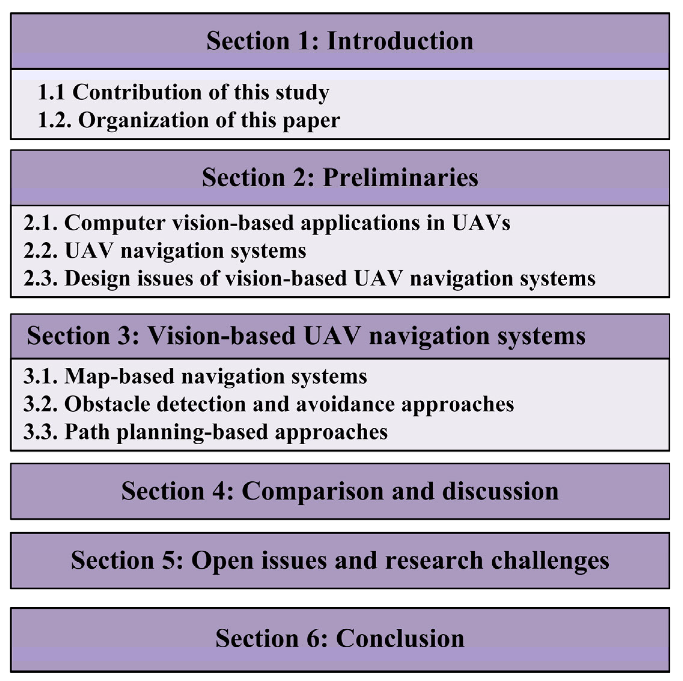
1.2. Organization of This Paper

This survey is organized into six sections, as shown in Figure 1. Below is an outline of the remainder of the paper.
In Section 2, we present various applications of computer vision in UAVs. We also present a comprehensive overview of UAV navigation systems. The critical design issues are discussed in this section. In Section 3, we discuss and review various vision-based UAV navigation systems. We present a taxonomy of the existing vision-based navigation systems. The working principle of each navigation technique is discussed in detail. In Section 4, we provide a comparative study of the existing vision-based navigation techniques with respect to various criteria. The major features, key characteristics, advantages, and limitations are summarized in a tabular manner and rigorously discussed. In Section 5, we present open issues and research challenges associated with vision-based UAV navigation techniques. Finally, the paper is concluded in Section 6.

2. Preliminaries

Computer vision plays an integral role in most UAV applications. Applications range from regular aerial photography to more complex operations, such as rescue operations and aerial refueling. To provide reliable decisions and manage tasks, they require high levels of accuracy. Computer vision and image processing have proven their efficiency in a variety of applications for UAVs. The applications of autonomous drones are interesting, but they also pose challenges.

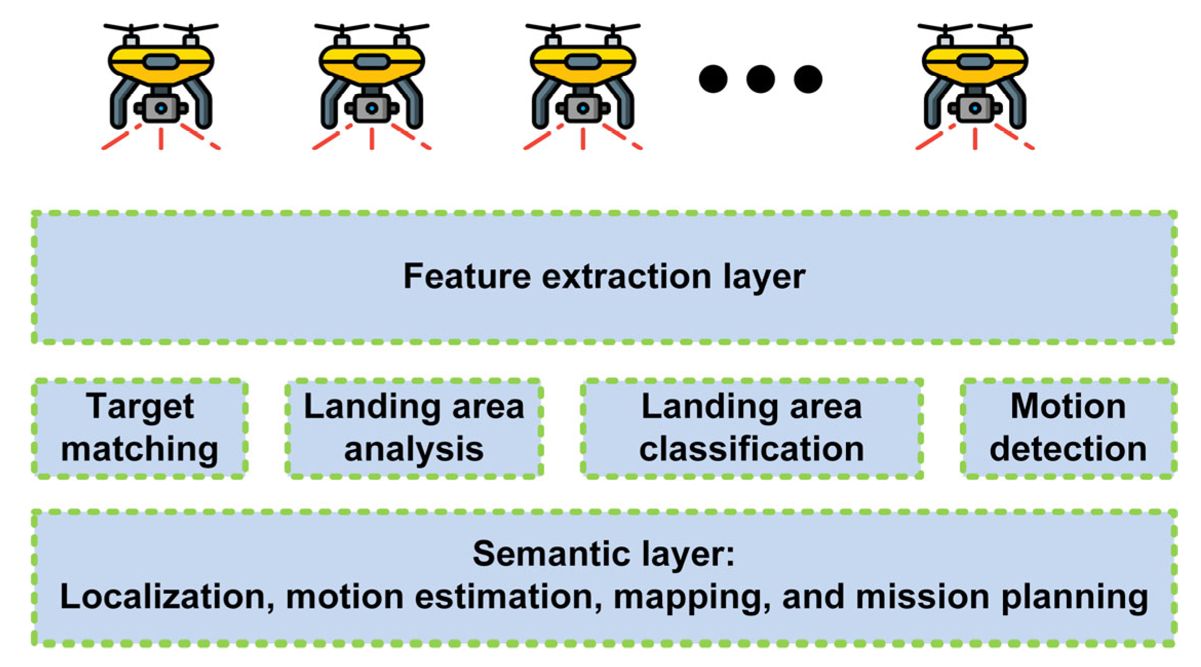
2.1. Computer Vision-Based Applications in UAVs

A peer-to-peer connection is established between UAVs and, thus, UAVs can coordinate and collaborate with each other [21]. An advantage of using a single cluster is that it is suitable for homogeneous and small-scale missions. UAVs performing multiple certain missions require a multi-cluster network. Every cluster head is responsible for downlink communication and communication with other cluster heads. In addition to VTOL vehicles, fixed-wing unmanned aerial vehicles also require autonomous takeoff and landing. To address the issue of vision-based takeoff and landing, different solutions have been proposed. Lucena et al. described a method that uses a back-stepping controller to implement autonomous takeoff and landing on a stationary landing pad [22]. The inertial measurement unit (IMU) and GPS data were fused with a Kalman filter to estimate the position, attitude, and speed of the quadcopter. To measure the distance between the landing pad and quadcopter, a light detection and ranging (LIDAR) sensor was used instead of a spatial device [23]. According to the results, the quadcopter was capable of autonomous takeoffs and landings. However, this system has the disadvantage of not being accurate in determining the attitude of the quadcopter, which is caused by errors in IMU and GPS measurements [24].
Both military and civil applications of UAVs rely on aerial imaging. Surveillance by UAVs is possible over battlefields, coasts, borders, forests, highways, and outdoor environments. In order to optimize the solutions in terms of time, the number of UAVs, autonomy, and other factors, different methods and approaches have been proposed. In an evaluation approach presented by Hazim et al. [25], the proposed algorithms and methods were evaluated with respect to their performance in autonomous surveillance tasks.
In recent years, aerial inspection has become one of the most popular applications for UAVs (primarily rotorcraft). Additionally, for safety and reduction in human risk, UAVs reduce operational costs and inspection time. Nevertheless, image stability must be maintained for all types of maneuvers [26]. In a variety of terrains and situations, UAVs are capable of inspecting buildings, bridges, wind turbines, boilers of power plants, power lines, and tunnels [27].
Air-to-air refueling, also known as autonomous aerial refueling (AAR) or in-flight refueling, consists of two main techniques [28]: (1) boom-and-receptacle refueling (BRR), which involves moving a flying tube (boom) from a tanker aircraft to a receiver aircraft to connect it to its receptacle; and (2) drogue-and-probe refueling (PDR), in which the receiver releases a flexible hose (drogue) and the tanker maintains its position to insert a rigid probe into the drogue. Tanker pilots are responsible for these complex duties and need to be well trained. Therefore, remote control of AAR operations further complicates UAVs. GPS and INS are used with various techniques to determine the position of the tanker relative to the receiver aircraft. Nevertheless, there are two main disadvantages associated with these techniques. First, GPS data may not be available in certain cases, especially if the receiver aircraft is larger than the tanker and interferes with the satellites. Another limitation is the integration drift of the INS measurements. Table 2 illustrates the use of computer vision in various UAV applications.

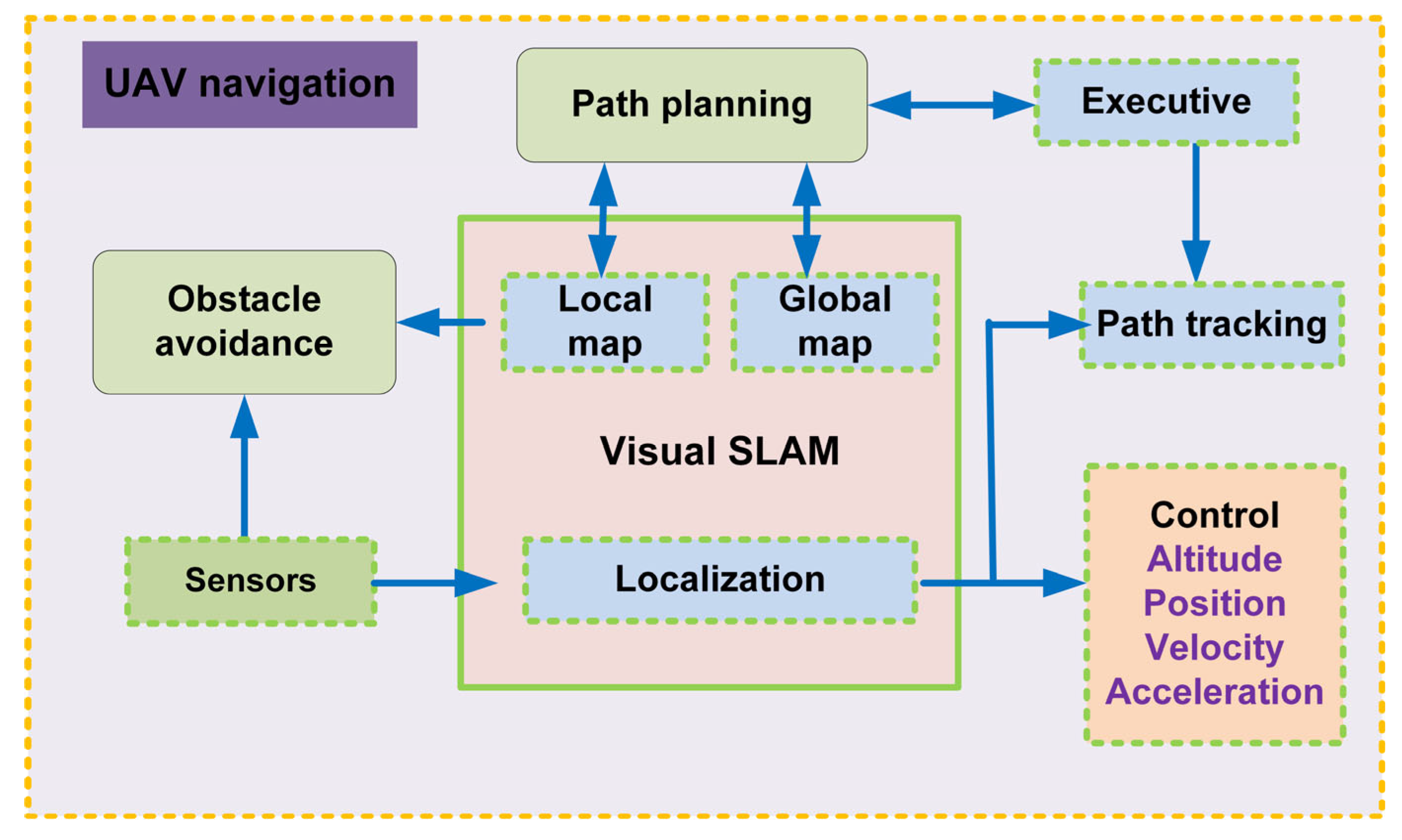
2.2. UAV Navigation Systems

Autonomy and flight stabilization accuracy have gained further importance in today’s UAVs. Navigation systems and their supporting subsystems are critical components of autonomous UAVs. Figure 2 demonstrates the use of the information from various sensors that the navigation system uses to estimate the position, velocity, and orientation of the UAV.
In addition, support systems perform relevant tasks, in particular, the detection and tracking (static or dynamic) or avoidance of obstacles. Increased levels of autonomy and flight stabilization require a robust and efficient navigation system [29]. Monocular cameras can be used to implement computer vision algorithms to enhance navigation. Navigation systems can be split into three main subsystems, as shown in Table 3: pose estimation, which uses two- and three-dimensional (3D) representations to estimate the position and attitude of the UAV; obstacle detection and avoidance, which detects and feeds back the position of the obstacles that it encounters; visual servoing (VS), which manages and sends maneuver commands to keep the UAV stable and following its path throughout its flight; and finally, the position estimation subsystem.

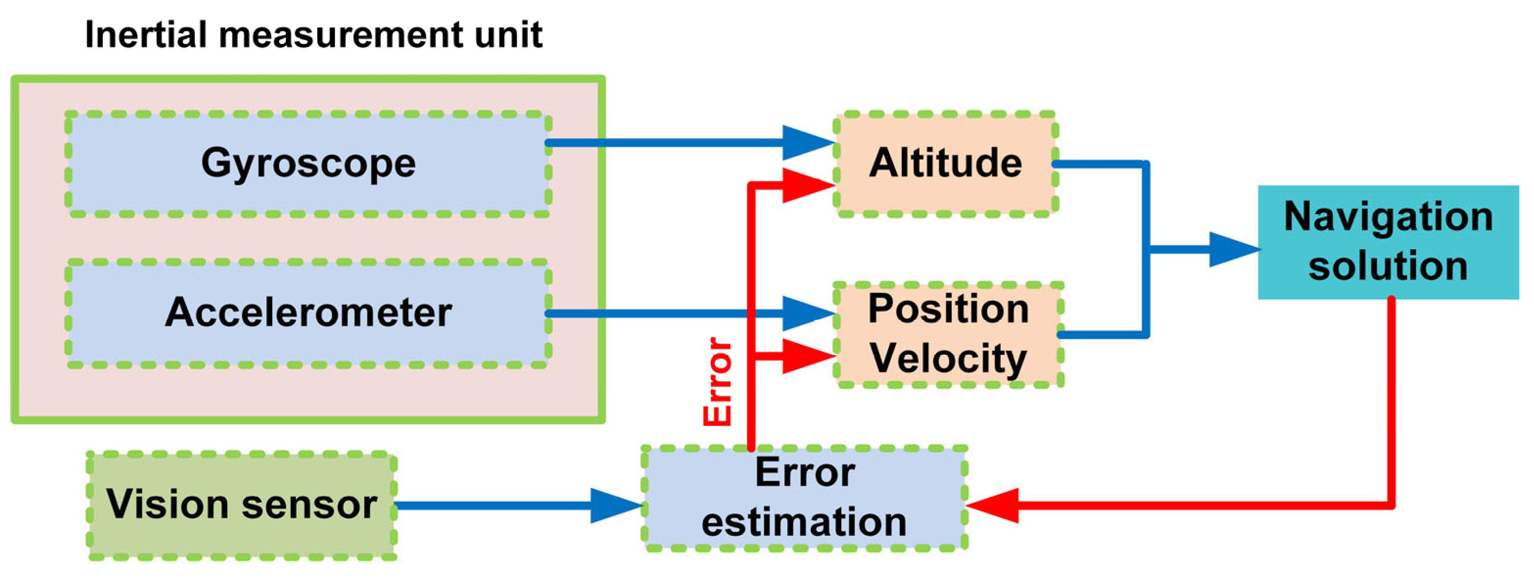
2.2.1. Pose Estimation

Pose estimation includes estimating the position and orientation of UAVs during motion based on data obtained from several sensors, including GPS, IMU, vision, laser, and ultrasonic sensors. Information obtained from various sensors can be separated or combined. Navigation and mapping processes require the estimation of position as a fundamental component.

GPS

The GPS, also known as a satellite-based navigation system (SNS), is considered one of the best methods for providing 3D positions to unmanned ground vehicles (UGVs), UAVs, and autonomous underwater vehicles (AUVs) [30]. GPS is commonly used to determine a UAV’s location during localization. Hui et al. used GPS to localize UAVs [31]. According to the authors, differential GPSs (DGPSs) demonstrate the effectiveness of this positioning method. DGPS reduces errors (satellite clock, satellite position, and delay errors) that cannot be reduced by the GPS receiver alone. To increase the accuracy of the positioning information, DGPS was integrated with a single-antenna receiver [26]. The precision of these systems is directly affected by the number of connected satellites. Buildings, forests, and mountains can significantly reduce satellite visibility in an urban environment. In addition, GPS is rendered ineffective in the absence of satellite signals, such as when flying indoors. An expensive external localization system, such as the Vicon motion capture system [32], is used to capture the motion of a UAV in an indoor environment.

GPS-Aided Systems

While stand-alone GPS can be useful for estimating vehicle location, it can also cause errors due to poor reception and jamming of satellite signals, resulting in loss of navigational data. For the purpose of preventing catastrophic control actions that may be caused by errors in estimating position, UAVs require a robust positioning system, for which various approaches are used. GPS-aided systems are an example of these approaches. The gathered GPS data are fused with data from other sensors. This multisensory fusion can consist of two or more sensors [33]. One of the most popular configurations is the GPS/INS approach, where the data from the INS and GPS are merged to compensate for the errors generated by both sensors and increase the accuracy of localization. Using a linear Kalman filter, Hao et al. [34] fused the data from a multiple-antenna GPS with the information from the onboard INS. Although the experiments were conducted on a ground vehicle, this algorithm was implemented for the UAVs.

Vision-Based Systems

As a result of the limitations and shortcomings of the previous systems, the vision-based pose estimation approaches have become an important topic in the field of intelligent vehicles [35]. In particular, visual pose estimation methods are based on information provided by the visual sensors of cameras. A variety of approaches and methods have been suggested, regardless of the type of vehicle and the purpose of the task. Different types of visual information are used in these methods, such as horizon detection, landmark tracking, and edge detection [36]. A vision system can also be classified by its structure as monocular, binocular, trinocular, or omnidirectional [37]. To solve the vision-based pose estimation problem, two well-known philosophies have been proposed: visual simultaneous localization and mapping (VSLAM) and visual odometry (VO).
As a general principle, VSLAM algorithms [38] aim at constructing a consistent map of the environment and simultaneously estimating the position of the UAV within the map. Different camera-based algorithms have been proposed to perform VSLAM on UAVs, including parallel tracking and mapping (PTAM) [39] and mono-simultaneous localization and mapping (MonoSLAM) [40], which were discussed by Michael et al. [41]. The UAV orientation and position were estimated using the VO algorithms [42]. The estimation processes are conducted sequentially (frame by frame) to determine the pose of the UAV. Monocular cameras or multiple-camera systems can be used to gather visual information. In contrast to VSLAM, VO algorithms calculate trajectories at each instant in time without preserving the previous positions. The VO method was first proposed by Nistér [43] using the traditional wheel odometry approach. A Harris corner [44] was detected in each frame to incrementally estimate the ground vehicle motion. By implementing a 5-point algorithm and random sample consensus (RANSAC), image features were matched between two frames and linked to the image trajectory [45].

2.2.2. Visual Obstacle Detection and Avoidance

Autonomous navigation systems must detect and avoid obstacles. Furthermore, this process is considered challenging, particularly for vision-based systems. Obstacle detection and avoidance have been solved using different approaches in vision-based navigation systems. A 3D model of the obstacle within the environment was constructed using approaches such as those suggested by Muhovic et al. [46]. The depth (distance) of obstacles has also been calculated in other studies [47]. Stereo cameras have been introduced to estimate the proximity of obstacles using techniques based on stereo cameras. By analyzing the disparity images and viewing angle, the system determines the size and position of the obstacles. In addition, this method calculates the relationship between the size of a detected obstacle and its distance from the UAV.

2.2.3. Visual Servoing

In UAV control systems, visual servoing is the process of using visual sensor information as feedback [48]. To stabilize UAVs, different inner-loop control systems have been employed, such as proportional–integral–derivative (PID), optimal control, sliding mode, fuzzy logic, and cascade control. Chen et al. [49] provided a detailed analysis of principles and theories related to UAV flight control systems. Altug et al. [50] evaluated two controllers (mode-based feedback linearizing and backstepping-like control) based on visual feedback. An external camera and onboard gyroscopes were used to estimate the UAV angles and positions. According to the simulations, feedback stabilization was less effective than the backstopping controller.

2.3. Design Issues of Vision-Based UAV Navigation Systems

In this section, we introduce a general framework for evaluating navigation systems. An ideal navigation system should be highly accurate, accessible, scalable, and cost-effective. Additionally, the navigation system should be simple to install and maintain and have low computational complexity.

2.3.1. Accuracy

The accuracy of a navigation system is the most important performance indicator. The presence of obstacles, multipath effects, dynamic scenes, and other factors may obstruct precise measurements of an agent in certain application environments. Sensors and applications play a significant role in determining the accuracy of measurements. Camera-only systems are more susceptible to featureless or incorrectly tracked features. Although significant progress has been made in vision-based navigation, many problems remain to be solved in order to realize a fully autonomous navigation system. Some of them are autonomous obstacle avoidance, optimal path discovery in dynamic scenarios, and task assignment in real time. Furthermore, UAV navigation necessitates a global or local 3D representation of the environment, and the added dimension requires more computing and storage. When a UAV navigates a large area for an extended period of time, it faces significant obstacles. Furthermore, the motion blur generated by rapid movement and rotation can easily cause tracking and localization failures during flight.

2.3.2. Availability

To effectively navigate, UAV systems must have access to technologies that do not require proprietary hardware and are readily available. As a result, navigation systems are likely to be adopted on a large scale. A wide range of UAVs are equipped with relatively inexpensive GPS chips. However, GPS chips do not provide high-accuracy navigation results and exhibit errors of up to several meters. With a partial or complete 3D map, we should not only find a collision-free path, but also minimize the length of the path and energy consumed. Although creating a 2D map is a relatively straightforward process, creating a 3D map becomes increasingly difficult as the dynamic and kinematic restrictions of UAVs become more complex. The local minimum problem still plagues modern path-planning algorithms because of this NP-hard problem. Thus, researchers continue to study and develop robust and effective methods for global optimization.

2.3.3. Complexity and Cost

The complexity of a navigation system is an important consideration in the design of drone communication systems and is usually associated with greater power requirements, infrastructure demands, and computational demands. In the case of an autonomous mission, a computationally complex system may not be able to operate on a miniature drone. Ideally, a system does not require any additional infrastructure costs or rare or unusual devices or systems. Accordingly, cost, accuracy, generalization, and scalability are determined by the complexity of the system. Even though UAVs and ground mobile robots have similar navigation systems, UAV navigation needs extensive development. To fly safely and steadily, the UAV must process a sizable amount of sensor data in real time, particularly for image processing, which considerably increases computational complexity. Consequently, navigating within the limits of low battery consumption and limited computational capacity has become a key challenge for UAVs.

2.3.4. Generalization

The degree of generalization is another aspect that should be considered when assessing the applicability of technologies. Practically, we would like to use the same type of hardware and algorithms for all navigation problems. However, each problem requires different features, such as size, weight, cost, accuracy, and operating environment. A single method cannot be applied in all situations. UAVs can be equipped with a variety of sensors because these sensors are becoming smaller and more precise. However, difficulties are likely to arise when combining several types of sensor data exhibiting varied noise characteristics and poor synchronization. Despite this, we anticipate superior pose prediction via multi-sensor data fusion, which will subsequently improve navigation performance. As IMUs are becoming smaller and less expensive, the integration of IMUs and visual measurements is gaining considerable traction.

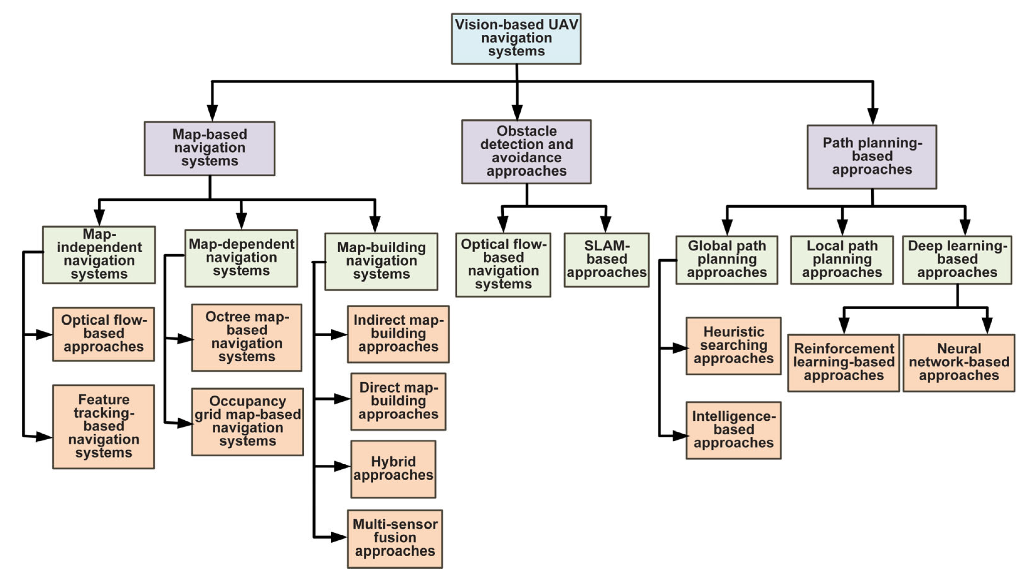
3. Vision-Based UAV Navigation Systems

Two perspectives exist on vision-based UAV navigation systems: mapping-based methods for visual localization and object detection and avoidance. Several visual localization methods follow maps. Therefore, we can divide them into three categories: map-independent, map-dependent, and map-building. A variety of methods can be used to detect objects, including optical flow and SLAM methods. For avoidance, vision-based approaches depend on two types of path planning, global and local. Figure 3 shows a detailed taxonomy of vision-based UAV navigation systems.

3.1. Map-Based Navigation Systems

The map-based system allows the UAV to navigate with detour behavior and movement planning capabilities based on the predefined map and laid-out environment. Maps can vary in their level of detailing, from a 3D model of an entire environment to a diagram of the interconnection of elements of an environment. Map-oriented navigation systems can be divided into three categories: map-independent, map-dependent, and map-building-based.

3.1.1. Map-Independent Navigation System

The map-independent navigation system operates without a known map, whereas UAVs navigate only by observing and extracting distinct features from their surroundings. Currently, optical flow and feature tracking methods are the most commonly used methods in map-independent navigation systems.

Optical Flow-Based Navigation Systems

There are two categories of optical flow techniques: global techniques [51] and local techniques [52]. The main constraint of the global optical flow is the smooth movement of the neighboring pixels. However, the local optical flow method follows the method of differences and recognizes that the flow should be constant for all image pixels. In early 1993, an optical flow computation was applied for the first time to UAV navigation. According to Santos-Victor et al. [53], a UAV can estimate the position of an object using both-side views to mimic a bee’s flight behavior. First, it measures the optical speed of the two cameras compared to the divider separately. It moves along the focal line if they are the same; otherwise, it moves at the speed of small places ahead. Despite this, every time it is explored in a surface-less climate, it tends to exhibit lackluster results. We have seen the extraordinary improvement in optical streams and have made some leaps in the location and following fields from that point forward.
Herissé et al. [54] presented a nonlinear regulator for an upward VTOL automated flying vehicle, such as a UAV, that exploits an optical flow measurement to enable hover and landing control on a movable stage, such as the deck of a maritime vessel. The VTOL vehicle is outfitted with a base sensor suite (i.e., a camera and an IMU), which moves over an objective plane. Herissé et al. identified two particular concerns. To maintain a steady balance, the UAV should be adjusted according to the moving stage. Second, guidelines should be followed for vertical landing on a moving stage. Dense optical flow calculations can distinguish the movements of all moving objects, which play a significant role in high-level endeavors, such as surveillance and track shooting. A novel computer vision-based movement detection algorithm has been presented by Maier and Humenberger [55], which can be used for applications such as human detection by UAVs. To distinguish between static and moving scenes, the algorithm measures the deviation between successive images. This assumption is significant because lone pixels, in comparison with moving articles, can violate the epipolar geometry. To assess the major network, the authors presented another strategy for dismissing anomalies that has, in contrast to RANSAC, a predictable runtime and still delivers reliable results. They presented a novel neighborhood-based edge strategy, particularly for troublesome regions, a joined worldly smoothing methodology, and further anomaly disposal procedures.
The fundamental goal of this vision-based UAV route convention was to construct a better route framework. This issue is defined below, and is resolved using a molecular channel: to control assessment errors, a sound system investigation of the image grouping produced by a video recorder mounted on the UAV, rather than a digital elevation map (DEM) of the area of flight, was used to construct state and perception models of the molecule channel. The extended Kalman filter (EKF) determines the position of an aircraft by locking it onto terrain and estimating its velocity. Previously, Zhang et al. [56] utilized the EKF to develop a navigation system, whereas the EKF was used to obtain the position and orientation of the UAV by Zang et al. [57]. A DEM is required to solve the error estimation. The observation model was considerably more robust to stereo analysis. Therefore, ray tracing was not required, and the DEM calculated errors much better. The EKF was then replaced by a particle filter. This is much more lenient in that they selected the observation model and appropriately exploited states. Zang et al. [57] used simulated fly-by video data to estimate the results. Their use of the augmentation of the state and observation models makes the models more robust for filtering. Additionally, by combining the models with the particle filtering algorithm, they provided more latitude to estimate the positions and range of vehicles. These are the main contributions and strengths of this study. Using this work, UAVs can navigate through various difficult scenarios, such as disaster areas, natural calamities, and urban areas, with the use of image processing.
Zang et al. [56] aimed to develop a more robust vision-based UAV navigation protocol than other protocols to solve the problem of vision-based UAV navigation, classified as a tracking problem. An EKF was used to determine the position and velocity of a UAV. The video footage of the UAV camera was used with the help of a 3D DEM to match and recalibrate the output of the EKF to obtain a precise position and orientation of the vehicle. Kalman filter removes the noise by calculating the minimum mean square error. However, it works only for linear models. EKF has more advantages, such as less error in the results than a regular Kalman filter, and can be applied repeatedly to an algorithm. In addition, EKF works well with non-linear models. It can obtain the position by combining it with the Monte Carlo simulation. Zang et al. [56] used simulated fly-by video data from the ESRI ArcInfo software package [58] and data from the national map seamless server [59]. They simplified the approach using derivations of the EKF formulae and ignored general losses. They used an EKF to estimate the position using ray tracing with a 3D digital elevation map. The main contributions of this study are as follows: the proposed approach can be used in real-life situations to navigate UAVs in various difficult situations, such as disaster areas, natural calamities, urban areas, military reconnaissance, and rescue. As the above situations are independent of the GPS, the proposed approach may not be affected by the jamming of a signal.
A vision-based navigation system was proposed by Cho et al. [60] to perform coordinated and autonomous missions by UAVs, including formation flyovers and aerial refueling. They developed a neural network capable of performing AAR in a simulation with six degrees of freedom. Using the pole placement method, a time-variant tracking controller was implemented to generate the control command of the aircraft. This method works for both PDR and BRR in AAR. It considers turbulence, atmospheric disturbances, and other factors. The authors used binary images to remove noise and other trivial objects from images. This was followed by extracting features from these binary images and detecting the UAVs in front of them. The positioning and orientation of these UAVs were estimated based on these features.

Feature Tracking-Based Navigation Systems

The feature-tracking method has also become a standard and robust approach for visualizing localization using maps. These methods are suitable for tracking the invariant features of moving objects. Cho et al. [61] addressed several issues related to robotic spacecraft using a single calibrated monocular camera. A monocular camera for robotic spacecraft activities based on a known target configuration, for example, is hindered by sudden changes in illumination in low-Earth orbits, long-term tracking requirements for large target images that change in scale, background exceptions, and the requirement for (semi-)autonomous relative navigation under limited computing resources (fuel, computer hardware, etc.). Therefore, they proposed an overall navigation scheme in space that used three unique fixings. Initially, two different feature detectors were used to guarantee dependable element locations over diverse distances. To identify the fiducial marker’s visual highlights, a fast feature selection/filtering technique was applied. Then, a feature pattern matching algorithm using strong relative enlistment was used for a route to accomplish hearty mechanized re-obtaining if there should be an occurrence of a lost objective. Furthermore, a probabilistic graphical model fitted with fixed-slack smoothing based on factor charts was applied to precisely determine the relative interpretation and direction of six-degrees-of-freedom (6-DOF) state gauges and their speeds.
Li and Yang [62] built a completely autonomous mobile device based on behavior-based artificial intelligence (AI). Modules were developed for versatile robots to operate at different levels of skill and practice, and each module was independently designed. These modules can be easily integrated into the robot framework to improve their capabilities without modifying any current modules. The most elevated layer in the design was realized using a vision-based landmark recognition system. Using genetic algorithms, a search method for recognizing advanced pictures was proposed and applied to detect fake milestones by examining all predefined designs. The vision layer can create ideal practices associated with various landmarks. A combination of eight ultrasonic sensors was designed to implement obstacle-avoidance behavior through a set of fuzzy rules. During robot navigation, invariant features were reserved for various perspectives, distances, and lighting conditions. Szenher [63] created an image-based visual homing algorithm that works robustly and efficiently in dynamic visual indoor environments. They investigated environments in which lighting conditions or landmark locations changed between the capture of snapshots and current images.
Casetti et al. [64] proposed a guidance system with safe-landing capabilities and a vision-based navigation system. The feature detection algorithm was used to mainly track landmarks so that large helicopter-sized UAVs could land safely without helipads. This work is useful in the instance where a UAV that loses its GPS signal before landing is in flight or returns to the base station. The overall mechanism operates through several steps. The authors used a feature called the scale-invariant feature transform (SIFT) [65], which is invariant to image translation, scaling, and rotation. At this point, the camera footage is captured as an image, and the image is divided into multiple sub-images based on its resolution. Subsequently, to satisfy the required depth estimation of determining a safe area for landing, the authors used two different scenarios. The first scenario requires images to be captured from a constant height and with pure translational motion; however, this constraint can be overcome because the control system is able to guarantee these flight conditions during the inspection of the landing area. Using the second approach, the helicopter moves to maintain its position as it approaches the landing phase and descends in a pure vertical landing manner. In this situation, the feature-based vision system is employed to inspect the landing area, using the same set of local features as previously used. Subsequently, the authors executed a slope detection algorithm to filter any inconsistent data and determine feature matches in two adjacent images. The authors used a popular UAV control structure called a hierarchical control structure with the following two main aspects: high-level control (strategy and task management) and low-level control (actuator control behavior), as shown in Figure 4.
Vetrella and Fasano [66] implemented a sensor output-based vision-based tracking system. Their primary goal was to apply the method in either a challenging GPS environment or for a UAV with nominal GPS coverage. This is because a swarm of UAVs operates cooperatively for distributed guidance and navigation. The proposed architecture framework is suitable for GPS-challenging environments. To simplify the working principle, the authors introduced a father–son formation. Father UAVs have reliable GPS data and are unaffected by signal absorption, jamming, and multipath phenomena. Thus, the performance of the father UAV needs no improvement; instead, the improvement of the son UAV should be emphasized. This study exploits only line-of-sight (LOS) communication between the son and father obtained by the onboard camera, which provides interactions, such as information sharing, body reference frame (BRF), and relative sensing between these two UAVs. Most of the processing occurs on the son UAV. In particular, this vision-based tracking system generates BRF LOSs that are employed as extra measurements in a sensor fusion approach based on a tight connection with the INS, magnetic sensor, GPS, and EKF. Furthermore, for nominal GPS coverage, altitude data were obtained from the sensors onboard the father UAV to acquire baselines in the northeast down (NED) reference frame, and DGPS was used among UAVs. Figure 5 shows the overall working mechanism of the proposed architecture.

3.1.2. Map-Dependent Navigation Systems

A map-dependent approach relies on the spatial layout of the environment to enable UAVs to navigate with detour behavior and plan their movements. Two different types of maps are primarily used in these methods: octree and occupancy grid maps. The maps contain a wide range of information, which includes 3D models of a complete environment and maps showing the interconnections between the elements of that environment. Furthermore, when the 3D data are directly stored in a 2D map, they can be applied in indoor environments, such as office areas, wide hall rooms, or plain outdoor fields, where height information is less critical. However, in more complex environments such as traditional urban areas, obstacles are irregular, making the use of 2D models more challenging. Therefore, a 3D occupancy model must be deployed, where the probability distribution for height is updated, rather than a one-dimensional value. Consequently, rearranging obstacles that have a non-standard profile, such as tunnels, trees, building walls, and objects arranged in a distinctive manner, is possible.
Considering the issues mentioned above, Fournier et al. [67] presented a novel mapping approach that demonstrated a unique mapping methodology. Specifically, data from a volumetric sensor created by the Defense Research and Development Canada (DRDC), Valcartier, were used to create a 3D representation of the environment. The model was saved in an octree structure and updated via ray tracing. The columns of the 3D model were projected onto a 2D plane to create a 2.5D map. They also employed an exploration method to deploy a modified version of the frontier-based strategy for efficient exploration of the area. Basic navigation algorithms were also added to build a fully autonomous system.
Gutmann et al. [68] collected and processed data using a stereo vision sensor, which were then used to create a 3D environment map. The core of this method was an expanded scan-line grouping technique that properly splits range data into planar pieces. This efficiently reduced the data noise caused by the stereo vision algorithm while predicting the depth. To depict 3D settings, a multi-volume occupancy grid, which explicitly stores information about both barriers and open spaces, was employed by Dryanovski et al. [69]. This grid enabled progressive rectification of previous potentially incorrect sensor readings by filtering and fusing new positive and negative sensor data.
A vision-based position-estimation technique was presented by Saranya et al. [70]. As a first step, the authors introduced traditional methods, such as GNSS and INS, to determine the position of the UAV. GPS data are commonly used to measure the signal, and triangulation is used to estimate the position and velocity. The UAV is navigated using an INS and various sensors, such as accelerometers, gyroscopes, altimeters, and magnetometers. However, the authors pointed out that GNSS systems can be easily jammed, and an INS may encounter errors in the output that increase with time. This error is called the drift error and can only be minimized and not prevented. Thus, an advanced approach is required to mitigate the limitations of traditional systems. The authors introduced vision-based position estimation, which acts as a backup for both methodologies. In this case, the latitude and longitude values obtained previously can be utilized by integrating with the Google static map application programming interface (API). Subsequently, matching techniques, such as normalized cross-correlation with prior edge extraction and a RANSAC feature detection algorithm, were used to complete the system. In the implementation setup, the authors used a camera and transmitter that acted as a UAV to transmit video data to the ground station. At the ground station, another computer processed the transmitted video footage and GPS data and implemented matching techniques.

3.1.3. Map-Building-Based Navigation Systems

Navigating an accurate map of any environment is extremely difficult for any UAV, owing to the complex and rough terrain of the surroundings. Moreover, owing to natural calamities, such as storms or heavy rain, UAVs cannot easily recognize the target area. Therefore, generating maps during navigating through a complex environment is an effective solution. Generally, map-building approaches are widely used in autonomous and semi-autonomous fields and have become widely accepted and more popular owing to the rapid development of simultaneous visual localization and mapping [71]. The size and shape of UAVs have decreased to a certain extent, thereby limiting their payload capacity. As a result, researchers have become increasingly interested in using basic (single and multiple) cameras rather than the usual complicated laser radar and sonar. The Stanford CART robot was one of the first attempts at using a map-building approach using a single camera [72]. Subsequently, an interest operator technique was developed to recognize the 3D coordinates of pictures. The system showed the 3D coordinates of objects that were kept on a 2 m grid. Although this technology can rebuild obstacles in the environment, it is currently incapable of modeling real large-scale environments. Vision-based SLAM algorithms, which are based on cameras, have been significantly developed for simultaneously recovering camera poses and structure of the environment and have used three types of methods: indirect, direct, and hybrid methods, depending on the visual sensor image processing.

Indirect Map-Building Approaches

Indirect approaches identify and extract characteristics. Instead of accessing pictures explicitly, it is used as input for motion estimation and localization methods. Features are often intended to be rotation and perspective invariant and robust against motion blur and noise. Various types of feature detectors and descriptors have been developed over the last three decades as part of a thorough study of feature detection and description [62]. Consequently, most contemporary SLAM algorithms are based on these features.
Davison [73] suggested that the study of real-time mapping, despite being rarely camera-based, is more significant than the offline structure from motion approaches because of the primary focus on uncertainty propagation. A factored sampling approach and motion modeling were used to develop a top-down Bayesian framework for single-camera localization, which took advantage of information-guided active measurement and tackled the challenging problem of real-time feature initialization. The development and active measurement of a sparse map of landmarks in real time allow for resilient localization, allowing locations to be revisited after periods of neglect and localization to continue even when few features are visible. SLAM-based visual algorithms have reached a milestone and greatly influenced future approaches, which essentially separate the SLAM system into two parallel independent categories: tracking and mapping.
Klein and Murray [74] demonstrated a technique for predicting the camera position in a novel scenario. They presented a system, which was previously constructed by modifying SLAM algorithms established for robotic exploration, designed specifically to follow a handheld camera in a tiny, augmented reality (AR) workspace. They separated tracking and mapping into two jobs in parallel on a dual-core computer: one thread tracked irregular handheld motion, while the other created a 3D map of point characteristics from previously recorded video frames. This enables the application of computationally costly batch optimization techniques that are not normally associated with real-time operations. Consequently, a system that generates comprehensive maps with thousands of landmarks that can be monitored at frame rates with accuracy and resilience has been developed. Mahon et al. [75] proposed a large-scale visual navigation method that combines SLAM. An expanded information filter was used in the estimation process based on viewpoint-augmented navigation (VAN) architecture. Data collected by an autonomous underwater vehicle, visually surveying sponge beds, illustrated this method. Loop-closure observations of a stereo vision system were used to adjust the predicted vehicle trajectory provided by the dead reckoning sensors.
Celik et al. [76] used a monocular camera to offer a unique indoor navigation and range approach. They suggested a combined SLAM method that underlines indoor aerial vehicle applications. They also used a completely self-contained micro aerial vehicle (MAV) with onboard image processing and SLAM capabilities to test the proposed methods. The range-measuring approach was based on fundamental adaptive processes for depth perception and pattern recognition in humans and animals. The navigation approach assumed that the environment was unknown, GPS was unavailable, and corner-like feature points and straight architectures could represent it.
Han and Chen [77] presented a multi-camera visual attitude estimation system based on multi-camera PTAM, which parallelizes the pose estimation and mapping modules and integrates the ego-motion estimates from many cameras. They also presented a standardized external parametric calibration method for numerous cameras with non-overlapping fields of view. Most indirect techniques, however, extract only unique feature points from images and can only rebuild a limited collection of points (traditionally corners). This type of approach is known as the sparse direct method because it can recreate only a sparse scene map. Consequently, researchers have been anticipating the development of dense indirect techniques for reconstructing dense maps. Valgaerts et al. [78] estimated the basic matrix and found dense correspondences using a dense energy-based approach. Ranftl et al. [79] used a segmented optical flow field to develop a high-resolution depth map from two successive frames. This implies that a picture may be densely reconstructed based on this framework by optimizing a convex algorithm.
Bavle et al. [80] proposed stereo visual–inertial SLAM. The inputs were synchronized and then passed to the awareness map, which was updated in two steps. The first was to use the newest pose for renewing, where the position of each occupied cell in the old map was detected in the new map. The occupancy state was then updated using the point cloud and applied ray casting. The occupied and non-occupied lists were sent to the local–global map, which generated two different maps. The maps were projected in 2D and local Euclidean signed distance fields (ESDFs) [81]. The distance between the ESDFs represents the Euclidean distance to the nearest occupied voxel [82]. The path-planning Fuxi kit consists of two parallel running planners: global and local planners. The kit aims at determining the shortest path and planning obstacle avoidance strategies. A 2D map was used as the input for the global planner. It aimed to determine the shortest path using an improved jump point search algorithm [83]. The outputs were the local set points provided to the local planner. Locally, the map avoids collisions and plans a dynamic trajectory. All maps were used for visualization.

Direct Map-Building-Based Approaches

Indirect techniques function well in a normal context, but are prone to being stuck in a texture-free world. Consequently, direct approaches have become popular over the past decade. In contrast to indirect techniques, the direct method optimizes the geometry parameters by utilizing the intensity information of all images, providing resistance to photometric and geometric aberrations. Furthermore, direct techniques are more likely to identify dense correspondences, allowing them to reconstruct dense maps at a higher computational cost. Silveira et al. [84] suggested a novel method for simultaneously obtaining correspondences, camera posture, scene structure, and lighting changes, using picture intensities as observations. The use of all available picture data resulted in more accurate estimations and avoided the inherent challenges of properly associating the features. In this instance, structural restrictions, such as chirality, stiffness, and those linked to illumination changes, can be applied to the method. The visual SLAM issue was reformulated as a nonlinear picture-alignment challenge. Newcombe et al. [85] proposed dense tracking and mapping (DTAM), a real-time monocular SLAM system that uses direct techniques to estimate the 6DOF motion of the camera. With current commodity GPU hardware, dense surfaces can be built at a frame rate based on predicted detailed textured depth maps by frame rating the whole picture alignment.
Engel et al. [86] used GPUs and a probability approach to produce a semi-dense map. Kummerle et al. [87] considered the scale factor and used graph optimization over the Sim3 model, enabling scale drift correction and loop closure detection. A navigation system based on the known location of landmarks was proposed by Lan and Jianmei [88]. The process of continuously correcting the noise in the IMU image as a variable state increased the calculation time.

Hybrid Approaches

Hybrid approaches combine both the direct and indirect approaches. As a first step, they initialize feature-related maps using indirect approaches. Second, for more accurate results, they constantly refines the camera poses using direct methods. To estimate the state of a UAV, Forster et al. [89] presented an innovative semi-direct approach called semi-direct monocular visual odometry (SVO). Motion estimation and point cloud mapping were implemented in two threads, similar to PTAM. A more accurate motion estimation was accomplished by directly using pixel brightness and gradient information, combining them with feature point alignment, and reducing the reprojection error for motion estimation. Subsequently, using only smartphone processors as the processing unit [89], they developed a computationally efficient system for real-time 3D reconstruction and landing-spot identification for UAVs. In contrast to PTAM, SVO requires a high-frame-rate camera to achieve real-time performance. The approach was primarily presented for onboard applications, with minimal computing capabilities.

Multi-Sensor Fusion Approaches

Laser scanners are particularly common in ground mobile robots because they provide access to high-quality 3D point clouds [90]. As their size decreases, UAVs can also be equipped with laser scanners. This allows the integration of many types of measurements from various types of sensors. The fusion of multiple sensors provides a more precise and robust estimate of UAV status using the timeliness and complementarity of multiple sensors. Lynen et al. [91] introduced the multi-sensor-fusion EKF (MSF-EKF), a general-purpose MSF-EKF that can handle various forms of delayed measurement inputs from many sensors and offer more accurate attitude estimates for UAV control and navigation. Magree and Johnson [92] presented an integrated navigation system that integrates optical and laser SLAM with an inertial navigation system based on EKF. The monocular visual SLAM system identifies data associations and estimates the state of UAVs, whereas the laser SLAM system uses a Monte Carlo framework for scan-to-map matching.

3.2. Obstacle Detection and Avoidance Approaches

Obstacle avoidance is a critical component of autonomous navigation because it can identify and transmit critical information about surrounding obstacles, thereby reducing the risk of collisions and pilot mistakes. Consequently, it has the potential to dramatically boost the autonomy of UAVs. Obstacle avoidance is based on detecting barriers and calculating the distances between UAVs and obstacles. When an obstacle approaches, the UAV is meant to avoid it or turn around, according to the instructions of the obstacle avoidance module. One method uses range finders, such as radar, ultrasonic, and infrared, to estimate distance. In addition, their narrow field of view and measuring range prevent them from gathering sufficient information in a complicated environment. Compared to this method, visual sensors can collect sizable visual data that can be processed and used to avoid obstacles. Obstacle avoidance approaches are divided into two categories: optical flow- and SLAM-based methods. Image processing was used [93] to overcome the obstacles. The use of optical flow can produce a local information flow and obtain a picture depth.

3.2.1. Optical Flow-Based Approaches

The study of optical flow discusses avoiding obstacles and collisions by analyzing images captured by a single camera. An optical flow method based on the Lucas–Kanade gradient approach was applied to acquire the tested structure in a 3D space environment (depth extraction). This method can be used to construct local information-flow patterns from a specific area of nearby sites. The proposed technique for locating obstacles and estimating their shapes was developed and implemented on a workstation with the μClinux real-time operating system. This method can be used to build local information flow patterns from a group of adjacent locations in a specified area. On a workstation with the μClinux real-time operating system, an approach for finding barriers and estimating their shapes was developed and implemented. During flight, a change in the barrier size was identified [94]. This method mimicked the human eye mechanism of items in the field of view, which enlarges with diminishing distance. It can detect obstacles by comparing sequential images and determining the distance from the obstacle. This study presented an innovative algorithm based on the size characteristics of the detected feature points that change over time. It also used the size ratio of the convexity of the features found from two consecutive frames in the drone motion.
Optical flow navigation approaches have also been developed for bionic insect vision. Strübbe et al. [95] suggested a simple non-iterative optical flow approach to measure the global optical flow and self-motion of the system, which was inspired by bee vision. The Reichardt model [96] is based on the visual nerve anatomy of insects as a fundamental local-motion detection unit. The authors investigated the hypothesis that when the signal-to-noise ratio (SNR) of the stimulus increases, the motion processing technique switches from Reichardt to the gradient detector. Local signal modulations were expected to diminish with an increase in the SNR. The authors used two methods to adjust the SNR at the input. The mean brightness was changed in one scenario. With increasing brightness, the SNR increases with the square root of the Poisson distribution of photon emission. In the second scenario, the pattern contrast was adjusted. The signal, and hence the SNR, grows linearly with contrast in a peak-to-peak comparison. The flow technique and sensor were developed [97] using the complex fly structure. To apply the theoretical validation to UAVs, insect vision algorithms were used. The authors created a visually driven autopilot for MAV-dubbed Octave as part of their research on biologically inspired micro-robotics (optical altitude control systems for autonomous vehicles). They demonstrated the possibility of a simultaneous altitude and speed control system based on a low-complexity optronic velocity sensor that predicts the downward optic flow. This velocity sensor was based on electrophysiological discoveries of on-the-fly elementary motion detectors (EMDs). They created a simple, 100-gram tethered helicopter device that can track the terrain above a randomly patterned surface. The total processing system was sufficiently light and could be placed on MAVs with only a few grams of avionic payload.
Recently, a physics student named Darius Merk developed a system inspired by insect vision that uses the speed of light to evaluate the distance between objects [98]. It is simple but effective because many insects in nature can sense nearby obstructions based on the intensity of light. During flight, the image motion on the retina of an insect produces a visual flow signal, and this optical flow presents spatial information for visual navigation. According to the intensity of light passing through the leaf gap, insects can quickly determine whether barriers can be safely traversed. However, the optical flow-based technique cannot determine precise distances, which limits its application to some missions. On the other hand, SLAM-based approaches can offer precise metric maps with a complex SLAM algorithm, allowing UAVs to navigate and avoid obstacles with more knowledge of the environment. Moreno-Armendariz and Calvo [99] described a method using a SLAM system to map previously unknown environments. To avoid static and dynamic barriers, a novel artificial potential field method was used. The primary goal of an autonomous vehicle is to travel through unfamiliar areas. Developing a map can accomplish this goal. The vehicle can establish paths between visited locations on its own using a map. Obtaining such a map with no prior knowledge of the surroundings or the robot’s initial position in the environment is a specific challenge. Avoiding static and dynamic impediments, on the other hand, necessitates the use of a revolutionary artificial potential field approach. Novel designs that overcome both difficulties are implemented on a field-programmable gate array (FPGA). The unique ideas were then tested on differential traction mobile robots, equipped with a computer vision system that travels through an unfamiliar controlled environment. The experimental findings revealed acceptable real-time performance.
Zhihai et al. [100] proposed another vision-based UAV navigation system that can avoid obstacles with the help of motion field estimation. A UAV is assumed to have a reasonable understanding of its linear velocity in the inertial frame (based on GPS data). The UAV gyroscope can provide a basic estimate of its orientation. Additionally, for the time being, the camera is assumed to have been positioned at the UAV’s center of gravity. The camera was assumed to have the same orientation as that of the body of the UAV. The image frame was captured using a video camera mounted on the UAV. As a result of classifying these image blocks, building edges, corners, road lines, and treetops can be estimated because each block has its own set of features. The authors applied a discrete cosine transform (DCT) to identify patterns or edges. In addition, the pixel values of the image were considered to compute the distance between the UAV and the object.
To address the issue of heavy sensors for obstacle detection, Lin and Peng [101] proposed a vision-based approach using a budget camera for object tracking. Map-based motion planning is primarily concerned with automatic steering to avoid obstacles during the mission. This is particularly critical at relatively low flight altitudes [102]. A natural setting containing many obstructions was used for the studies. The authors combined offline route planning and online collision-avoidance schemes for autonomous navigation management. The rapidly exploring random tree (RRT) algorithm was used to construct an initial path using an offline guiding method. The waypoints of the path were accompanied by the directions. An integrated camera was used to capture a series of images throughout the movement to create an optical flow field. During piloting, this was used to identify obstructions and establish a relationship between the movement of the UAV and encountered impediments. It was divided into multiple steps, beginning with image pre-processing and progressing via optical flow calculation, zone separation, and object recognition to the final judgment, as shown in Figure 6. Based on the smoothing restriction and illumination uniformity parameters, the authors proposed an optical flow estimate [103]. The approach uses a quadratic polynomial expansion to estimate the movement of nearby pixels and thus produces accurate results in terms of precision and speed. These studies were conducted in an outside area with different barriers, and the results revealed that the image analysis duration for a frame on the system was roughly six fps or 150–180 ms. The movement for every pixel was computed between two successive picture frames in more detail than sparse optical flow algorithms. However, the application of the collision avoidance algorithm is still limited. A few drawbacks of optical flow include light shift, sluggish camera shaking, and ambient noise in outdoor settings.

3.2.2. SLAM-Based Approaches

To deal with the inadequate light of interior environments and the reliance on the number of feature points, Bai et al. [104] developed a method for generating self-adaptive map feature points based on the PTAM algorithm, which is useful in GPS-deficient areas with real-time performance. UAVs can fly inside buildings when deployed for counterterrorism and disaster relief. GPS signals may be blocked in an enclosed interior environment, obstructing the determination of UAV whereabouts. Furthermore, the complex interior environment poses problems for flight safety. Consequently, real-time detection of complex situations and avoidance of impediments are required. In this study, the PTAM algorithm was introduced into the UAV ground control module. They modified the algorithm and built a self-adaptive map feature point generating mechanism to deal with low indoor light, fewer feature points, and other challenges, thereby lowering the system’s reliance on the number of feature points and illumination conditions. This paper presented an obstacle recognition algorithm and warning mechanism for a ground control module based on the aforementioned foundation. Finally, the authors tested this approach using a small quadrotor UAV. The results suggest that when dealing with unknown indoor situations, the self-localization approach can provide obstacle warnings during flight. The results show that this approach, which is critical for researching autonomous positioning and flight safety for UAVs under GPS-less conditions, works well in real time.
Esrafilian and Taghirad [105] proposed an approach based on oriented fast and rotated brief SLAM (ORB-SLAM). It begins by processing video data by computing the 3D location of the UAV and generating a sparse point-cloud map. The sparse map was then enriched to increase its density. Finally, using the potential field method and swiftly traversing a random tree, it produces a collision-free road layout. This paper described a commercial quadrotor with a monocular vision-based autonomous flight and obstacle avoidance system. The video feed of the front camera and the drone’s navigation data were wirelessly transmitted to a ground station laptop. The received data were processed by ORB-SLAM, which uses vision to compute the 3D position of the robot and a 3D sparse map of the environment in the form of a point cloud. The method was proposed to enrich the reconstructed map, and a Kalman filter was employed for sensor fusion. A linear feature was used to calculate the scaling factor of the monocular slam. A PID controller was also developed to control the 3D position. Finally, a collision-free road map was constructed using the potential field method and RRT path-planning technique. The proposed algorithms were also experimentally verified.
Potena et al. [106] used a nonlinear model predictive control (NMPC) controller to improve vision-based navigation by adding dynamic and static collision avoidance functionalities. The proposed technique illustrated designed obstacles considering their speed and uncertainty, thus allowing safe operation over the projected trajectory. The authors proposed a management approach that simultaneously integrated collision avoidance and perception restrictions. They also used a configurable barrier characterization that allows the simulation of various obstructions while also encoding the unpredictability and velocity of the obstacles. The surrounding environment is full of static barriers, and dynamic barriers may arise from nowhere and cause disruptions. This approach causes the UAV to maneuver across a revised safe route to respond to an identified item. Target recognition, VS, and vision-based guidance are applications that can be leveraged by the proposed technique. The challenge is expressed as an optimal control problem (OCP) and addressed in a receding horizon manner. NMPC provides a possible answer to the OCP at every drive cycle, and only the first input of the most efficient route is used to control the robot. The OCP is resolved within a few milliseconds using numerical optimization, ensuring adequate responsiveness to re-plan the course once unexpected obstructions are recognized, thereby allowing real-time vehicle management. The integration of errors and object speeding into ellipsoids is also possible with the suggested protocol, enabling it to cope with dynamic impediments. Yang et al. [107] designed a reliable GPS-denied object identification approach and an accurate relative position and speed analysis approach to address the challenges of landing a UAV on a moving platform. A vision-based guidance system for UAVs was built using these two technologies. Methods such as location estimation, marker identification, and ellipse detection are reliable and rapid, making them ideal for practical use. With its simplistic design and ease of recognition by UAVs while flying, the authors employed a black-and-white square ID marker to distinguish the circle. They chose a circle as the landmark. Owing to the high number of command updates required to balance the UAV, a comprehensive real-time algorithm was used. The techniques presented in this study can be used to track and detect targets by UAVs in freight transit situations and maritime rescue missions.

3.3. Path-Planning-Based Approaches

Path planning is an imperative activity in UAV navigation, which entails determining the most efficient path from the starting to destination point based on a set of performance characteristics (such as the lowest cost of work, shortest flight duration, and shortest route). The UAV must also avoid obstructions throughout the process, as shown in Figure 7. This problem can be divided into two versions depending on the type of environmental information used to compute an ideal path: global and local route planning. Global path planning aims at determining the best possible path based on a global geographical map. However, it is insufficient for controlling a UAV in real time, particularly when other activities must be completed quickly or unanticipated impediments arise during flight. Consequently, local path planning must continuously receive sensor data from the surrounding environment and compute a collision-free path in real time.

3.3.1. Global Path-Planning Approaches

A global path planner creates an initial path based on the locations of the starting and target points. Thus, a global map is referred to as a static map. Two common methods of planning global paths are the use of heuristic search methods and a succession of clever algorithms.

Heuristic Searching Methods

The A-star algorithm, which is derived from the basic Dijkstra algorithm, is a common heuristic search method. The A-star algorithm has been considerably refined in recent years, and many enhanced heuristic search algorithms have been developed. Vachtsevanos et al. [108] built a digital map from an orographic database and used a modified A-star algorithm to select the optimal track. This paper describes a hybrid hardware/software framework, which supports advanced control and mission-planning algorithms, for autonomous aircraft. To consider unmodeled dynamics, solve uncertainty issues, and provide a flexible platform for development and operator interface, the employment of intelligent fuzzy-logic-based and object-modeling approaches was emphasized. Fuzzy logic is used in various vehicle modules, such as route planners, fuzzy navigators, fault-tolerant tools, and flight controllers. Rouse [109] used the heuristic A-star technique to accomplish optimal path planning based on distinct grid-point value functions along the estimated path.
A prototype route planner was created in the framework of mission planning for air interdiction. A realistic geographical scenario was partitioned into a rectangular grid, with nine attributes assigned to each intersection. These features were combined to generate a pattern vector describing the properties of each intersection. Pilots scored a representative sample of these vectors based on the desirability of overflying sites with specific attributes. These data were used to create a minimum distance pattern classifier. Then, using an “algorithm A” search routine, a route planner was created. The route planner relies on a heuristic that combines the distance and pattern classifier outputs to determine a low-cost path for a target. The sparse A-star search (SAS) for path planning was introduced by Szczerba et al. [110]. This approach effectively reduced the computational complexity by introducing limitations to space searching during path planning. In both military and commercial applications, route planning is a challenging task. Routing algorithms use a predetermined cost function in order to calculate a route that has the lowest cost. Unfortunately, in certain mission scenarios, such a method may not prove effective. The author described a unique route-planning methodology for quickly and accurately generating mission-adaptable routes. The routes are calculated in real time and may accommodate various mission limitations, such as the minimum route leg length, maximum turning angle, route distance limit, and a fixed approach vector to the objective location.
Stentz [111] created the dynamic A-star method, commonly known as the D-star algorithm, for partially or unknown dynamic environments. It can update its map of unfamiliar environments when it detects new barriers along its path. In the scientific literature, planning trajectories for mobile robots has received much attention. The majority of research assumes that a robot has a complete and accurate picture of its surroundings before the beginning of flight; nevertheless, the problem of partially known surroundings has received less attention. An exploration robot or robot that must proceed to a destination area without the assistance of a floorplan or terrain map is used in this scenario. An initial course based on the available information can be designed using existing methods and then altered locally, or the entire path can be replicated. The robot detects impediments using its sensors, compromising either optimality or computational efficiency. Stentz presented D*, a novel algorithm capable of efficiently, optimally, and completely designing courses in unknown, partially known, and changing situations.
In [112], the authors discussed how UAVs could be used in difficult environments and how to plan and track an optimal path for optimal performance with minimal energy and time consumption. To assist the UAV in navigating obstacles, the authors developed a hybrid algorithm called Harris hawk optimization (HHO)–gray wolf optimization (GWO), which was tested against other metaheuristic algorithms.

Intelligence-Based Approaches

Scholars have attempted to address global path-planning problems using intelligent algorithms and have proposed various intelligent searching strategies in recent years. The genetic and simulated annealing arithmetic (SAA) algorithms are two of the most common intelligent algorithms and were used to study path planning [113]. The path adaptation function was evaluated using the genetic algorithm’s crossover and mutation operations and metropolis criterion, which improves the path-planning efficiency. This research introduced SAACO, a novel path-planning methodology that combines framed-quad-tree representation with hybrid-simulated annealing (SA) and ant colony optimization (ACO) algorithms to increase path-planning efficiency. The use of a framed-quad-tree representation enhances the decomposition efficiency of the environment and retains the representation capacity of the map. SA and ACO have been used for the robot path planning problem, and there have been numerous accomplishments in the last year. Many types of SA rely on random starting points, and automatically determining ways to provide better early estimations of solution sets is still a hot topic in this study.
For the SA runs, we employed ACO to provide a suitable starting solution. It was found that the proposed SAACO algorithm can successfully handle the robot path-planning problem, enabling the robot to seek a given destination while avoiding collisions and thereby increasing the speed of the UAV navigation. The robustness, self-adaptivity, and other qualities of this approach have also been demonstrated. Enhanced simulated annealing and conjugate direction approaches were utilized to optimize global path planning [114]. Mission situations with restricted ground control station access or beyond the LOS necessitate autonomous safe navigation skills and the ongoing extension of existing and potentially obsolete obstacle knowledge. The proposed method is a novel combination of 3D perception and global techniques. Sparse obstacles were extracted for incremental global path plan (GPP) using a locally bound sensor fusion methodology. During flight, a stereo camera analyzes depth images to assess the field of view along the flight path ahead. A 3D occupancy grid was constructed in stages. An approximated polygonal globe model was built to alleviate the high data rate and storage requirements of grid-type maps. Prisms and ground planes were utilized to create a compressed representation that allows the system to constantly renew and refresh its obstacle knowledge. To provide a collision-free path at all times, an incremental heuristic path planner uses both a priori information and incremental obstacle updates. The mapping results from the flight tests demonstrate the functionality of the onboard environment modeling using real sensor data. The viability of path planning is proven in a simulated setting by considering the model changes within the vehicle’s field of view.

3.3.2. Local Path-Planning Approaches

Local route planning uses local environmental data and UAV’s state estimation to plan a local path that dynamically avoids collisions. Path planning in a dynamic environment becomes a highly complex task because of unpredictable factors such as item movements in a dynamic environment. In this situation, path-planning algorithms must adapt to the dynamic properties of the environment by gathering information (such as size, shape, and location) about unknown elements of the environment via a variety of sensors. Spatial search methods, artificial potential field techniques, fuzzy logic techniques, and neural network methods are examples of traditional local path-planning methods. In this section, we describe a few common path-planning approaches. Wang et al. [115] applied a virtual force approach, in which a UAV was moved from its surroundings into an abstract artificial gravitational field environment. According to the mobile robot, the target point has both “attraction” and “repulsion”, and the robot is governed by these two forces and gradually advances toward the target location. The authors proposed a distributed control system for a group of mobile robots. This method was distributed in the sense that all robots, or at least the majority of robots in some circumstances, planned their movements based on the group’s assigned aim and the observed positions of other robots. The authors illustrated the concept by describing an approximation of a very large number of robots in a circle, simple polygon, or line segment in the plane. They also demonstrated uniform dispersion of robots within a circle or convex polygon in space. Finally, they demonstrated the division of robots into two or more groups. Most robots followed a similar, simple algorithm in most circumstances. A simulation was conducted to demonstrate the effectiveness of the method.
Souza et al. [116] demonstrated a method for calculating the path through obstacles using the artificial potential field method. Path planning is one of the most critical issues in UAVs for determining the best route between source and destination. Although numerous studies exist on UAV path-planning challenges in the literature, target location and identification concerns persist owing to the rapid mobility of UAVs. To address these challenges, the best decisions for various mission-critical functions performed by UAVs must be made. As part of these decisions, the UAVs must be located relative to a map or graph of the mission environment. To solve the abovementioned challenges, the authors examined several UAV path-planning strategies that have been employed throughout the years. The path-planning approaches were aimed at offering a collision-free environment for UAVs and determining the best and shortest paths. Having path-planning tools to compute a safe path to the end destination within the shortest possible time is critical. Representative techniques, cooperative techniques, and non-cooperative approaches are the three basic path-planning strategies for UAVs. These methodologies were used to explore and evaluate the coverage and connection of UAVs’ network communication. The existing suggestions were comprehensively studied based on each category of UAV path planning. For a better understanding, the text presents various comparison tables considering parameters, in particular path length, optimality, completeness, cost efficiency, time efficiency, energy efficiency, robustness, and collision avoidance. Many open research challenges based on UAV path planning and network communication have also been investigated to provide readers with deeper insights.
Genetic algorithms are a general method of solving optimization problems, particularly those that involve determining the best path to follow. They address the inheritance and evolution of biological phenomena. To achieve an ideal solution, the “survival strategy” and “survival of the fittest” principles have been used. Chromosome coding, population size, fitness function, genetic operation, and control parameters are the five main components of these principles. The evolutionary algorithm has been widely used in aviation path planning in several existing studies [117]. To plan 3D routes for multiple air vehicles across a dense threat environment, a route-planning methodology based on a class of adaptive search techniques known as genetic algorithms (GAs) is described. Shen et al. [117] presented a GA-based route planner that provided efficient vehicle routes while accommodating mission restrictions. This methodology has been demonstrated to be promising in preliminary experiments on GA-based air vehicle route planners. This study builds on prior work by incorporating a full hierarchy-based mission-management system. The results of several experiments are presented and discussed. The main goals of the experiments were investigating the effective configuration of classes of GA operators, determining GA operator parameter settings that will produce “near optimal” routes, investigating the use of a domain-specific mutation operator called “target bias mutation” for expediting convergence, and comparing the results to the well-known dynamic programming algorithm.
A neural network is a computational tool developed to reveal biological activities. Liu and Xu [118] presented an example of path planning using Hopfield networks. In ground, air, and autonomous submarine systems, the capacity to plan routes that avoid barriers and meet mission goals over time is required. The Hopfield model was used to propose a neural network solution for route planning. The study discussed the translation of topography information into a Hopfield network representation. Creating an energy function capable of reflecting the planning and mission limitations common to all three operating domains was prioritized. The route planning capability was demonstrated using genuine terrain database imagery with the energy function based on the goal point distance, terrain gradients, and feedback from the UAV’s altitude data. The progress in efforts to integrate the route planner into a larger vehicle planning scheme was highlighted. The ant colony algorithm [119] is a novel bio-inspired algorithm that replicates ant behavior. It imitates the behavioral traits of ants as a stochastic optimization approach, allowing it to reach outcomes by solving a sequence of complex combinatorial optimizations.
Yang et al. [120] initially used a coarse model of the environmental surroundings to provide initial knowledge and then refined it through local online computation. The model was updated by processing the image sequences and combining them with sensor data, and relied on digital elevation models (DEM) [121], which are extensively applied in earth sciences, to create an initial 3D model of the environment. Finally, the author depended on conventional optimization techniques, such as the Dijkstra algorithm, to determine the shortest path for computation, as shown in Figure 8. The cost function used was the sum of the three factors, which were scaled by the distance to the goal, terrain roughness, and flight altitude. On the other hand, the principal idea of the refining approach was to divide the local space into 3D cubic cells and then represent each cell by a grid point. They used the center of the cell as the point, and then used a depth map algorithm to determine the depth of each voxel. The voxels were grids of cubic volumes of equal size. Furthermore, the authors used the voxels to update the volumetric map as occupied or unoccupied. Then, a map was provided to the path-planning algorithm to avoid obstacles.
Urban search and rescue (USAR) missions have been proposed by Mittal et al. [122]. No prior environmental knowledge is required for their navigator, unlike some of the methodologies introduced to date. In addition, they created a novel synthetic dataset [123] for collapsed buildings in a simulation environment. The navigation system provides localization, mapping, and collision-free paths. Additionally, it can explore unstructured environments without prior information. Localization occurs by first exploring the area and building a map using depth images. Similar to the cost function introduced by Yang et al. [120], they presented an algorithm for landing based on four evaluation criteria: the flatness and inclination of the terrain, confidence in the depth information, steepness of the area, and intensity of the landing. As explained previously, the UAV builds an occupancy map using depth images acquired by the onboard camera. In their proposed algorithm, they created two maps. The first was implemented using the open-source probabilistic 3D mapping framework Octomap [124]. A light voxel-based local map was used for path planning. The second was the open-source 3D mesh reconstruction tool, Voxblox [125]. It communicates with the ground station for analysis and rescue planning. As such, map visualization can be considered. Finally, landing sites were clustered to avoid repeatability because the detection was on a frame-to-frame basis. A global list of landing sites, including the depth information and pose of the UAV, was updated if the new landing site had no existing neighbors on the list within a small distance. A pose is a combination of the position and orientation of an object. The authors used a minimum-jerk trajectory generator [126] with non-linear optimization for path planning.

3.3.3. Deep Learning-Based Approaches

Drones must use the most efficient machine-learning algorithms for perception, planning, and control to execute their missions as quickly as possible because of the limited energy storage capacity and low efficiency of rechargeable batteries. Deep reinforcement learning (DRL) has recently emerged as an effective method for addressing the navigation problems of unmanned aerial vehicles. However, the significant amount of interactive data generated by these systems cannot converge when UAVs navigate through dynamic environments with many rapidly moving obstacles.

Reinforcement Learning (RL)-Based Approaches

Reinforcement learning (RL)-based approaches have recently become popular for UAVs with limited computational power. Different optimization algorithms are applied to both local and global path-planning strategies in indoor and outdoor environments. These RL-based approaches aid in learning a control policy that tends to generalize over varying power constraints for the UAV navigation system, as shown in Figure 9. Maciel-Pearson et al. [127] elected to rapidly increase the learning and understanding of a UAV agent while exploring a partially viewable environment that mimicked real-world obstacles. They employed a two-state input method that combines the knowledge gained from the raw image with a map that includes positional information. Although the feature map from the present scene identifies crowded areas that should be avoided, these positional data enhance the knowledge of the location of the UAV and its distance from the target point. He et al. [128] suggested a DRL method for solving the problem of UAV navigation in an unknown environment. However, DRL algorithms are constrained by the data efficiency problem because they often require a sizable amount of data to achieve a respectable level of performance. They designed a novel learning framework that blends imitation learning and an RL-based approach on the twin delayed deep deterministic policy gradient (DDPG) (TD3) algorithm [129] to speed up the DRL training process. They also discussed training both policy and Q-value networks using expert demonstrations during the imitation phase. Both the temporal difference (TD) error and decayed imitation loss were utilized to update the pre-trained network when interacting with the environment to address the distribution mismatch problem while shifting from imitation to reinforcement learning.
Theile et al. [130] proposed a novel approach for controlling a camera-equipped UAV on a coverage path planning (CPP) mission with random start positions and various landing alternatives in a no-fly zone environment. Many approaches have been developed to address similar CPP challenges. This study used end-to-end RL to establish a control policy for UAVs that generalizes over a variety of power restrictions. Despite recent advances in battery technology, the maximum flying range of small UAVs remains a significant limitation, exacerbated by unpredictable fluctuations in power consumption. They trained a double deep Q-network (DDQN) to make control decisions for the UAV, balancing a restricted power budget and coverage goal using map-like input channels to transmit spatial information through a convolutional network layer agent. This method harmonizes complex goal structures with system restrictions and can be adapted to a wide range of contexts. They also contrasted CPP, in which the UAV aims at surveying a certain area, with data harvesting (DH), in which the UAV harvests data from distributed Internet of Things (IoT) sensor devices [131]. DDQNs with identical architectures are trained in distinctly different mission scenarios that use structured map information from the surrounding environment to decide movements that balance the mission goal with the navigation limitations. The navigation controller generates the control signal solely based on the current sensor data, with no optimization or configuration space searching, memory reduction, or computing requirements. The navigation problem is treated as a Markov decision process and is solved using the DRL approach. Some model explanation approaches are specifically provided to gain a better understanding of the trained network. During flight, decision-making conclusions are communicated visually and verbally as a result of feature attribution. There are still limitations to the feature attribution method as it provides some insight into deep neural networks. For example, attributions do not explain the convergence of gradient descent or mixing of the features by network to obtain an answer.

Neural Network-Based Approaches

In addition to RL-based learning approaches, neural network-based algorithms have also been proposed for both indoor [132] and outdoor [133] environments. In some unconstructed environments, such as forests, automatic trail navigation systems are capable of generalizing across different image resolutions. Furthermore, they have enabled UAVs with a wide range of sensor–payload capabilities to operate equally under such challenging conditions. According to [134], the authors proposed AI technologies such as deep learning and neural networks for spacecraft systems to resolve the problems related to their dynamics and navigation. The article discusses different artificial neural network architectures, their training methods, and the pros and cons of using them for particular types of problems. Furthermore, it examines how artificial intelligence can be integrated into spacecraft systems for the purpose of system identification, control synthesis, optical navigation, etc. On the other hand, a real-time 3D path planner was developed in [135] to autonomously navigate UAVs through obstacles. To determine collision-free paths, the proposed path planner uses AI and heuristic algorithms. It is, therefore, an ideal method of providing real-time guidance.

4. Comparison and Discussion

In this section, we compare the existing vision-based navigation systems. We compared the reviewed vision-based navigation systems among the groups. Table 4 summarizes the analysis of the various map-based UAV navigation systems in terms of types, methods used, the main theme of the article, functions, network environment, advantages, and limitations of the proposed approach. Similarly, Table 5 and Table 6 summarize the comparison of various approaches to object detection and path planning for UAV navigation based on their proposed methods, main ideas, and functions. It can be observed from Table 5 and Table 6 that machine-learning-based approaches exhibit high performance but require considerable computing power. The navigator aims to fly the UAV successfully without an obstacle collision. Additionally, it determines the shortest path to the destination. Furthermore, it is used to define the appropriate landing sites for rescue operations. Navigators typically include three modules: localization, mapping, and path planning.
The map-based navigation approaches, widely used for UAVs, are presented in Table 4. Due to the requirement for a camera-based navigation system over scenes with uniform textures, a camera-based navigation system cannot infer geometrical information from an image. Furthermore, perception algorithms should be resilient to recurrent outlier measurements generated by low-level image processing, such as optical flow and feature matching. We also presented the advantages and drawbacks of each navigation technique. The main advantage of map-based UAV navigation systems is their simplicity. Nevertheless, several disadvantages, such as limited accuracy, slow motion, no visualization, limited applications, and limited memory management, are present owing to discarding depth and relying on sensors for planning. System complexity and computational cost are major limitations of map-based UAV navigation systems. The complexity and computational costs of map-based UAV navigation systems are limited.
A comprehensive comparison of the obstacle detection and avoidance approaches reviewed is presented in Table 5. Localization provides an exploration of the flight area. Several approaches can be used, including GPS as a reference frame model. The next step is to analyze the data and create a map that contains details of the obstacle positions. In the map, each cell was classified as occupied or unoccupied. In other words, it accurately determined the locations of the obstacles. All path-planning and object-detection-based navigation techniques produced highly accurate results. A few techniques have several shortcomings, such as a lack of visualization, limited applications, and limited memory organization. However, the SLAM-based approach showed excellent accuracy in object detection, but required a high computational cost.
Finally, in Table 6, we provided a comparison of path-planning approaches for navigation systems concerning various performance parameters. The path-planning module uses an appropriate search algorithm to determine the shortest route. This process is known as mapping. Therefore, navigators depend on visual approaches to refine this process. Various algorithms, such as Octomap, Voxblox, and ESDFs, have been developed for navigation. Furthermore, the map provides information about factors used as a cost function in the path-planning module, such as depth, distance, and energy consumption. Eventually, algorithms such as Dijkstra’s algorithm and jump point search are used for path optimization. The machine learning (ML)-based approach showed higher accuracy but required high computational costs.

5. Open Issues and Research Challenges

In this section, we summarize and discuss important open issues and research challenges that motivate further research in this emerging domain. As crucial challenges are introduced by the increasing demand, we discuss the four major issues of scalability, computational power, reliability, and robustness in vision-based UAV navigation systems.

5.1. Scalability

In this article, the major contributions in each category of vision-based navigation, perception, and control for unmanned aerial systems are discussed. Visual sensor integration in UAVs is an area of research that attracts enormous resources but lacks solid experimental evaluation. Compared with conventional robots, UAVs can provide a challenging testbed for computer vision applications for a variety of reasons. Typically, the dimensions of an aircraft are larger than those of a mobile robot. Thus, image-processing algorithms must be capable of robustly providing visual information in real time and have the ability to compensate for rough changes in the image sequence and changes in 3D information. However, SLAM algorithms, for visual applications, have been developed by the computer-vision society. However, most of them cannot be directly utilized in UAVs because of the computational power and energy limitations of UAVs. More specifically, aircraft have a limited ability to generate thrust to maintain their airborne status, which limits their capacity for sensing and computing. To avoid instabilities associated with the fast dynamics of aerial platforms, minimizing delays and compensating for noise in state computations is essential. Unlike ground vehicles, UAVs cannot simply cease operations in the presence of considerable uncertainty in state estimation, resulting in incoherent control commands to the aerial vehicle.

5.2. Computational Power

The UAV may possibly exhibit unpredictable behavior, such as an increase or decrease in speed or oscillation, and may ultimately crash if the computational power is insufficient to update the velocity and attitude in time. UAVs have the ability to operate at a variety of altitudes and orientations, resulting in a sudden appearance and disappearance of obstacles and targets; therefore, computer vision algorithms must be able to respond very quickly to changes in the scene (dynamic scenery). Notably, the majority of the presented contributions assume that UAVs will fly at low speeds to compensate for the rapid changes in the scene. Consequently, dynamic scenes pose a significant challenge. Considering the large area of aerial platforms, resulting in large maps containing more information than ground vehicles, which is another challenge in SLAM frameworks, is important. When pursuing a target, object tracking methods must be robust to occlusions, image noise, vehicle disturbances, and illumination variations. When the target remains within the field of view but is obscured by another object or not clearly visible from the sensor, the tracker must continue to function to estimate the target’s trajectory, recover the process, and work in harmony with the UAV controller. As a result, highly sophisticated and robust control schemes are required for optimally closing the loop using visual data. Computer vision applications have undeniably moved beyond their infancy and have made great strides toward understanding and approaching autonomous aircraft. Because various positions, attitudes, and rate controllers have been proposed for UAVs, this topic has attracted considerable attention from the research community. Therefore, to achieve greater levels of autonomy, a reliable link must be established between vision algorithms and control theory.

5.3. Reliability

To increase the reliability of a vision system, the camera exposure time can be automatically adjusted by software. Batteries are the primary source of power for UAVs, allowing them to perform all their functions; however, their capacity is limited for lengthy missions. Furthermore, marker and ellipse detection techniques may be further enhanced by merging them with the Hough transform and machine learning approaches. For movement analysis of possible impediments, the optical flow approach must be combined with additional methods. Optical flow calculation can be used for real-time scene analysis, when ground truth for evaluating the design is nonexistent. In recent years, more sophisticated image-based techniques have been studied because most of the work does not consider dynamic impediments.

5.4. Robustness

With the rapid advancement of computer vision and the growing popularity of mini-UAVs, their combination has become a hot topic of research. This study focused on three areas of vision-based UAV navigation. The key to autonomous navigation is localization and mapping, which also provides position and environmental information to UAVs. Obstacle avoidance and path planning are critical for safe and swift UAV arrival at a target area. The topic of vision-based UAV navigation, which relies solely on visual sensors to navigate in dynamic, complex, and large-scale settings, is yet to be solved and is a burgeoning field of study. We also discovered that the limited power and perceptual capabilities of a single UAV make it impossible for it to perform certain tasks. With the advancement of autonomous navigation, many UAVs can simultaneously perform similar tasks. Several RL-based approaches have been proposed for both indoor and outdoor environments, based on known targets. This remains undecipherable for unknown destination targets. Moreover, multiple targets were identified. In other words, finding an optimal path-based algorithm for multiple unknown targets is an open issue. Energy consumption is also an open issue in this sector. For optimal path selection, applying the least-squares or K-means algorithm is worthwhile. The sensor nodes used in the architecture may be dead or have hidden node problems.

6. Conclusions

Recently, UAVs have gained increasing attention in this research field. The navigator aims at successfully flying the UAV without colliding with obstacles. Navigation techniques for UAVs are imperative issues that have drawn significant attention from researchers. Over the past few years, several UAV navigation techniques have been proposed. A navigator typically consists of three modules: localization, mapping, and path planning. Localization provides an exploration of the flight area. Several navigation approaches can be used for navigation, including GPS, reference frames, and models. The next step is analyzing the data and creating a map that contains details of the obstacle positions. In this map, each cell is classified as occupied or unoccupied. In other words, it accurately determines the position of the obstacles. Then, it feeds the path-planning module with the details for determining the shortest path by applying a proper search algorithm, a process known as mapping. Recently, the advantages and improvements of computer vision algorithms have been demonstrated through real-world results in challenging conditions, such as pose estimation, aerial obstacle avoidance, and navigation. In this paper, we presented a brief overview of vision-based UAV navigation systems and a taxonomy of existing vision-based navigation techniques. Various vision-based navigation techniques have been thoroughly reviewed and analyzed based on their capabilities and potential utility. Moreover, we provided a list of open issues and future research challenges at the end of the survey.
Multiple potential research directions can be provided for further research into vision-based UAV navigation systems. Currently, UAVs possess several powerful characteristics that could lead to their use as pioneering elements in a wide variety of applications in the near future. Special features, such as lightweight chassis and versatile movement, are combined with certain characteristics, such as versatile movement. Therefore, there is a potential that could be tapped using onboard sensors; therefore, UAVs have received considerable research attention. Today, the scientific community focuses on developing more effective schemes for using visual servoing technologies and SLAM algorithms. Furthermore, many resources are now devoted to visual–inertial state estimation to combine the advantages of both areas. Developing a reliable visual–inertial state estimation system will be a standard procedure and fundamental element of every aerial agent. UAV position and orientation are estimated using visual cues from cameras and inertial measurements from an IMU. Furthermore, elaborate schemes for online mapping will be investigated and refined for dynamic environments. The development of robotic arms and tools for UAVs, which can be used for aerial manipulation and maintenance, is currently underway. Multi-sensor fusion improves localization performance by combining information from multiple sensors, such as cameras, LIDAR, and GPS. Future research will examine floating-base manipulators for either single or cooperative task completion. Because of the varying center of gravity and external disturbances caused by the interaction, operating an aerial vehicle with a manipulator is not a straightforward process, and many challenges must be overcome. This capability entails challenging vision-based tasks and is expected to revolutionize the use of UAVs. Further research in this area is necessary to overcome these challenges and reduce the limitations of the current approaches.

Author Contributions

Conceptualization, M.Y.A., M.M.A. and S.M.; methodology, M.M.A.; validation, M.Y.A. and S.M.; investigation, M.Y.A. and M.M.A.; resources, M.Y.A. and M.M.A.; writing—original draft preparation, M.Y.A. and M.M.A.; writing—review and editing, S.M.; supervision, S.M.; project administration, S.M.; funding acquisition, S.M. All authors have read and agreed to the published version of the manuscript.

Funding

This work was supported in part by a research fund from Chosun University (2022).

Data Availability Statement

Not applicable.

Acknowledgments

The authors thank the editor and anonymous reviewers for their helpful comments on improving the quality of this paper. We would like to express our sincere thanks to Masud An Nur Islam Fahim, Nazmus Saqib, and Shafkat Khan Siam for explaining vision-based navigation.

Conflicts of Interest

The authors declare no conflict of interest.

References

  1. Wei, Z.; Zhu, M.; Zhang, N.; Wang, L.; Zou, Y.; Meng, Z.; Wu, H.; Feng, Z. UAV-assisted data collection for internet of things: A survey. IEEE Internet Things J. 2022, 9, 15460–15483. [Google Scholar] [CrossRef]
  2. Arafat, M.Y.; Moh, S. Routing protocols for Unmanned Aerial Vehicle Networks: A survey. IEEE Access 2019, 7, 99694–99720. [Google Scholar] [CrossRef]
  3. Alam, M.M.; Arafat, M.Y.; Moh, S.; Shen, J. Topology control algorithms in multi-unmanned aerial vehicle networks: An extensive survey. J. Netw. Comput. Appl. 2022, 207, 103495. [Google Scholar] [CrossRef]
  4. Poudel, S.; Moh, S. Task assignment algorithms for Unmanned Aerial Vehicle Networks: A comprehensive survey. Veh. Commun. 2022, 35, 100469. [Google Scholar] [CrossRef]
  5. Sonkar, S.; Kumar, P.; George, R.C.; Yuvaraj, T.P.; Philip, D.; Ghosh, A.K. Real-time object detection and recognition using fixed-wing Lale VTOL UAV. IEEE Sens. J. 2022, 22, 20738–20747. [Google Scholar] [CrossRef]
  6. Arafat, M.Y.; Moh, S. Localization and clustering based on swarm intelligence in UAV Networks for Emergency Communications. IEEE Internet Things J. 2019, 6, 8958–8976. [Google Scholar] [CrossRef]
  7. Alam, M.M.; Moh, S. Joint Topology Control and routing in a UAV swarm for crowd surveillance. J. Netw. Comput. Appl. 2022, 204, 103427. [Google Scholar] [CrossRef]
  8. Kanellakis, C.; Nikolakopoulos, G. Survey on computer vision for uavs: Current developments and trends. J. Intell. Robot. Syst. 2017, 87, 141–168. [Google Scholar] [CrossRef] [Green Version]
  9. Al-Kaff, A.; Martín, D.; García, F.; de Escalera, A.; María Armingol, J. Survey of computer vision algorithms and applications for unmanned aerial vehicles. Expert Syst. Appl. 2018, 92, 447–463. [Google Scholar] [CrossRef]
  10. Arafat, M.Y.; Moh, S. Bio-inspired approaches for energy-efficient localization and clustering in UAV networks for monitoring wildfires in remote areas. IEEE Access 2021, 9, 18649–18669. [Google Scholar] [CrossRef]
  11. Wang, Y.; Wang, H.; Liu, B.; Liu, Y.; Wu, J.; Lu, Z. A visual navigation framework for the aerial recovery of uavs. IEEE Trans. Instrum. Meas. 2021, 70, 5019713. [Google Scholar] [CrossRef]
  12. Arafat, M.Y.; Moh, S. Location-aided delay tolerant routing protocol in UAV networks for Post-Disaster Operation. IEEE Access 2018, 6, 59891–59906. [Google Scholar] [CrossRef]
  13. Miclea, V.-C.; Nedevschi, S. Monocular depth estimation with improved long-range accuracy for UAV environment perception. IEEE Trans. Geosci. Remote Sens. 2022, 60, 5602215. [Google Scholar] [CrossRef]
  14. Zhao, X.; Pu, F.; Wang, Z.; Chen, H.; Xu, Z. Detection, tracking, and geolocation of moving vehicle from UAV using monocular camera. IEEE Access 2019, 7, 101160–101170. [Google Scholar] [CrossRef]
  15. Wilson, A.N.; Kumar, A.; Jha, A.; Cenkeramaddi, L.R. Embedded Sensors, Communication Technologies, computing platforms and Machine Learning for uavs: A Review. IEEE Sens. J. 2022, 22, 1807–1826. [Google Scholar] [CrossRef]
  16. Yang, T.; Li, Z.; Zhang, F.; Xie, B.; Li, J.; Liu, L. Panoramic UAV surveillance and recycling system based on structure-free camera array. IEEE Access 2019, 7, 25763–25778. [Google Scholar] [CrossRef]
  17. Arafat, M.Y.; Moh, S. A q-learning-based topology-aware routing protocol for flying ad hoc networks. IEEE Internet Things J. 2022, 9, 1985–2000. [Google Scholar] [CrossRef]
  18. Tang, Y.; Hu, Y.; Cui, J.; Liao, F.; Lao, M.; Lin, F.; Teo, R.S. Vision-aided multi-uav autonomous flocking in GPS-denied environment. IEEE Trans. Ind. Electron. 2019, 66, 616–626. [Google Scholar] [CrossRef]
  19. Qian, J.; Pei, L.; Zou, D.; Liu, P. Optical flow-based gait modeling algorithm for pedestrian navigation using smartphone sensors. IEEE Sens. J. 2015, 15, 6797–6804. [Google Scholar] [CrossRef]
  20. Qian, J.; Chen, K.; Chen, Q.; Yang, Y.; Zhang, J.; Chen, S. Robust visual-lidar simultaneous localization and mapping system for UAV. IEEE Geosci. Remote Sens. Lett. 2022, 19, 6502105. [Google Scholar] [CrossRef]
  21. Arafat, M.Y.; Moh, S. A survey on cluster-based routing protocols for Unmanned Aerial Vehicle Networks. IEEE Access 2019, 7, 498–516. [Google Scholar] [CrossRef]
  22. De Lucena, A.N.; Da Silva, B.M.; Goncalves, L.M. Double hybrid tailsitter unmanned aerial vehicle with vertical takeoff and landing. IEEE Access 2022, 10, 32938–32953. [Google Scholar] [CrossRef]
  23. Diels, L.; Vlaminck, M.; De Wit, B.; Philips, W.; Luong, H. On the optimal mounting angle for a spinning lidar on a UAV. IEEE Sens. J. 2022, 22, 21240–21247. [Google Scholar] [CrossRef]
  24. Arafat, M.Y.; Moh, S. JRCS: Joint Routing and charging strategy for logistics drones. IEEE Internet Things J. 2022, 9, 21751–21764. [Google Scholar] [CrossRef]
  25. Shakhatreh, H.; Sawalmeh, A.H.; Al-Fuqaha, A.; Dou, Z.; Almaita, E.; Khalil, I.; Othman, N.S.; Khreishah, A.; Guizani, M. Unmanned Aerial Vehicles (uavs): A survey on civil applications and key research challenges. IEEE Access 2019, 7, 48572–48634. [Google Scholar] [CrossRef]
  26. Cho, O.-H.; Ban, K.-J.; Kim, E.-K. Stabilized UAV flight system design for Structure Safety Inspection. In Proceedings of the 16th International Conference on Advanced Communication Technology, PyeongChang, Republic of Korea, 16–19 February 2014. [Google Scholar] [CrossRef] [Green Version]
  27. Arafat, M.Y.; Poudel, S.; Moh, S. Medium access control protocols for flying Ad Hoc Networks: A Review. IEEE Sens. J. 2021, 21, 4097–4121. [Google Scholar] [CrossRef]
  28. Li, B.; Mu, C.; Wu, B. A survey of vision based autonomous aerial refueling for unmanned aerial vehicles. In Proceedings of the 2012 Third International Conference on Intelligent Control and Information Processing, Dalian, China, 15–17 July 2012. [Google Scholar] [CrossRef]
  29. Dong, J.; Ren, X.; Han, S.; Luo, S. UAV Vision aided INS/odometer integration for Land Vehicle Autonomous Navigation. IEEE Trans. Veh. Technol. 2022, 71, 4825–4840. [Google Scholar] [CrossRef]
  30. Alam, M.M.; Moh, S. Survey on Q-learning-based position-aware routing protocols in flying ad hoc networks. Electronics 2022, 11, 1099. [Google Scholar] [CrossRef]
  31. Hui, Y.; Xhiping, C.; Shanjia, X.; Shisong, W. An unmanned air vehicle (UAV) GPS location and Navigation System. ICMMT’98. In Proceedings of the 1998 International Conference on Microwave and Millimeter Wave Technology, (Cat. No.98EX106), Beijing, China, 18–20 August 1998. [Google Scholar] [CrossRef]
  32. Gomes, L.L.; Leal, L.; Oliveira, T.R.; Cunha, J.P.V.S.; Revoredo, T.C. Unmanned Quadcopter control using a motion capture system. IEEE Lat. Am. Trans. 2016, 14, 3606–3613. [Google Scholar] [CrossRef]
  33. Alarcón, F.; García, M.; Maza, I.; Viguria, A.; Ollero, A. A Precise and GNSS-Free Landing System on Moving Platforms for Rotary-Wing UAVs. Sensors 2019, 19, 886. [Google Scholar] [CrossRef] [Green Version]
  34. Hao, Y.; Xu, A.; Sui, X.; Wang, Y. A Modified Extended Kalman Filter for a Two-Antenna GPS/INS Vehicular Navigation System. Sensors 2018, 18, 3809. [Google Scholar] [CrossRef] [PubMed] [Green Version]
  35. Pavel, M.I.; Tan, S.Y.; Abdullah, A. Vision-Based Autonomous Vehicle Systems Based on Deep Learning: A Systematic Literature Review. Appl. Sci. 2022, 12, 6831. [Google Scholar] [CrossRef]
  36. Lin, J.; Wang, Y.; Miao, Z.; Zhong, H.; Fierro, R. Low-complexity control for vision-based landing of quadrotor UAV on unknown moving platform. IEEE Trans. Ind. Inform. 2022, 18, 5348–5358. [Google Scholar] [CrossRef]
  37. González-Sieira, A.; Cores, D.; Mucientes, M.; Bugarín, A. Autonomous Navigation for uavs managing motion and sensing uncertainty. Robot. Auton. Syst. 2020, 126, 103455. [Google Scholar] [CrossRef]
  38. Bresson, G.; Alsayed, Z.; Yu, L.; Glaser, S. Simultaneous localization and mapping: A survey of current trends in autonomous driving. IEEE Trans. Intell. Veh. 2017, 2, 194–220. [Google Scholar] [CrossRef] [Green Version]
  39. Wang, S.; Lv, X.; Li, J.; Ye, D. Coarse semantic-based motion removal for robust mapping in dynamic environments. IEEE Access 2020, 8, 74048–74064. [Google Scholar] [CrossRef]
  40. Davison, A.J.; Reid, I.D.; Molton, N.D.; Stasse, O. MonoSLAM: Real-time single camera slam. IEEE Trans. Pattern Anal. Mach. Intell. 2007, 29, 1052–1067. [Google Scholar] [CrossRef] [Green Version]
  41. Blösch, M.; Weiss, S.; Scaramuzza, D.; Siegwart, R. Vision based MAV navigation in unknown and unstructured environments. In Proceedings of the 2010 IEEE International Conference on Robotics and Automation 2010, Anchorage, AK, USA, 3–7 May 2010. [Google Scholar] [CrossRef] [Green Version]
  42. Xie, X.; Yang, T.; Ning, Y.; Zhang, F.; Zhang, Y. A Monocular Visual Odometry Method Based on Virtual-Real Hybrid Map in Low-Texture Outdoor Environment. Sensors 2021, 21, 3394. [Google Scholar] [CrossRef]
  43. Nistér, D.; Naroditsky, O.; Bergen, J. Visual odometry for ground vehicle applications. J. Field Robot. 2006, 23, 3–20. [Google Scholar] [CrossRef]
  44. Harris, C.G.; Stephens, M.J. A Combined Corner and Edge Detector. In Proceedings of the Alvey Vision Conference, Citeseer, Manchester, UK, 31 August–2 September 1988. [Google Scholar]
  45. Jiao, Y.; Wang, Y.; Ding, X.; Fu, B.; Huang, S.; Xiong, R. 2-entity random sample consensus for robust visual localization: Framework, methods, and verifications. IEEE Trans. Ind. Electron. 2021, 68, 4519–4528. [Google Scholar] [CrossRef]
  46. Muhovic, J.; Mandeljc, R.; Bovcon, B.; Kristan, M.; Pers, J. Obstacle tracking for unmanned surface vessels using 3-D Point Cloud. IEEE J. Ocean. Eng. 2020, 45, 786–798. [Google Scholar] [CrossRef]
  47. Fabrizio, F.; De Luca, A. Real-time computation of distance to dynamic obstacles with multiple depth sensors. IEEE Robot. Autom. Lett. 2017, 2, 56–63. [Google Scholar] [CrossRef] [Green Version]
  48. Keipour, A.; Pereira, G.A.S.; Bonatti, R.; Garg, R.; Rastogi, P.; Dubey, G.; Scherer, S. Visual Servoing Approach to Autonomous UAV Landing on a Moving Vehicle. Sensors 2022, 22, 6549. [Google Scholar] [CrossRef] [PubMed]
  49. Chen, C.-W.; Hung, H.-A.; Yang, P.-H.; Cheng, T.-H. Visual Servoing of a Moving Target by an Unmanned Aerial Vehicle. Sensors 2021, 21, 5708. [Google Scholar] [CrossRef] [PubMed]
  50. Altug, E.; Ostrowski, J.P.; Mahony, R. Control of a quadrotor helicopter using visual feedback. In Proceedings of the 2002 IEEE International Conference on Robotics and Automation (Cat. No.02CH37292), Washington, DC, USA, 11–15 May 2002. [Google Scholar] [CrossRef]
  51. Horn, B.K.P.; Schunck, B.G. Determining optical flow. Artif. Intell. 1981, 17, 185–203. [Google Scholar] [CrossRef] [Green Version]
  52. Lucas, B.D.; Kanade, T. An Iterative Image Registration Technique with an Application to Stereo Vision. In Proceedings of the 7th International Joint Conference on Artificial Intelligence—Volume 2, Vancouver, Canada, 24–28 August 1981; pp. 674–679. [Google Scholar] [CrossRef]
  53. Santos-Victor, J.; Sandini, G.; Curotto, F.; Garibaldi, S. Divergent stereo for robot navigation: Learning from bees. In Proceedings of the IEEE Conference on Computer Vision and Pattern Recognition, New York, NY, USA, 15–17 June 1993. [Google Scholar] [CrossRef]
  54. Herissé, B.; Hamel, T.; Mahony, R.; Russotto, F.-X. Landing a VTOL unmanned aerial vehicle on a moving platform using optical flow. IEEE Trans. Robot. 2012, 28, 77–89. [Google Scholar] [CrossRef]
  55. Maier, J.; Humenberger, M. Movement detection based on dense optical flow for unmanned aerial vehicles. Int. J. Adv. Robot. Syst. 2013, 10, 146. [Google Scholar] [CrossRef] [Green Version]
  56. Zhang, J.; Wu, Y.; Liu, W.; Chen, X. Novel approach to position and orientation estimation in vision-based UAV navigation. IEEE Trans. Aerosp. Electron. Syst. 2010, 46, 687–700. [Google Scholar] [CrossRef]
  57. Zhang, J.; Liu, W.; Wu, Y. Novel technique for vision-based UAV navigation. IEEE Trans. Aerosp. Electron. Syst. 2011, 47, 2731–2741. [Google Scholar] [CrossRef]
  58. ESRI Inc. ArcView 8.1 and ArcInfo 8.1. 2004. Available online: http://www.esri.com/ (accessed on 1 June 2022).
  59. USGS National Map Seamless Server. 2010. Available online: http://seamless.usgs.gov (accessed on 1 June 2022).
  60. Khansari-Zadeh, S.M.; Saghafi, F. Vision-based navigation in autonomous close proximity operations using Neural Networks. IEEE Trans. Aerosp. Electron. Syst. 2011, 47, 864–883. [Google Scholar] [CrossRef]
  61. Cho, D.-M.; Tsiotras, P.; Zhang, G.; Holzinger, M. Robust feature detection, acquisition and tracking for relative navigation in space with a known target. In Proceedings of the AIAA Guidance, Navigation, and Control (GNC) Conference, Boston, MA, USA, 8–11 August 2013. [Google Scholar] [CrossRef] [Green Version]
  62. Li, J.; Allinson, N.M. A comprehensive review of current local features for Computer Vision. Neurocomputing 2008, 71, 1771–1787. [Google Scholar] [CrossRef]
  63. Szenher, M.D. Visual Homing in Dynamic Indoor Environments. Available online: http://hdl.handle.net/1842/3193 (accessed on 15 November 2022).
  64. Cesetti, A.; Frontoni, E.; Mancini, A.; Zingaretti, P.; Longhi, S. A Vision-based guidance system for UAV navigation and safe landing using natural landmarks. J. Intell. Robot. Syst. 2009, 57, 233–257. [Google Scholar] [CrossRef]
  65. Wertz, J.R. Spacecraft Attitude Determination and Control; Kluwer Academic Publishers: Dordrecht, The Netherlands, 1978. [Google Scholar]
  66. Vetrella, A.R.; Fasano, G. Cooperative UAV navigation under nominal GPS coverage and in GPS-challenging environments. In Proceedings of the 2016 IEEE 2nd International Forum on Research and Technologies for Society and Industry Leveraging a better tomorrow (RTSI) 2016, Bologna, Italy, 7–9 September 2016. [Google Scholar] [CrossRef]
  67. Fournier, J.; Ricard, B.; Laurendeau, D. Mapping and exploration of complex environments using persistent 3D model. In Proceedings of the Fourth Canadian Conference on Computer and Robot Vision (CRV ‘07) 2007, Montreal, QC, Canada, 28–30 May 2007. [Google Scholar] [CrossRef]
  68. Gutmann, J.-S.; Fukuchi, M.; Fujita, M. 3D perception and Environment Map Generation for humanoid robot navigation. Int. J. Robot. Res. 2008, 27, 1117–1134. [Google Scholar] [CrossRef]
  69. Dryanovski, I.; Morris, W.; Xiao, J. Multi-volume occupancy grids: An efficient probabilistic 3D Mapping Model for Micro Aerial Vehicles. In Proceedings of the 2010 IEEE/RSJ International Conference on Intelligent Robots and Systems 2010, Taipei, Taiwan, 18–22 October 2010. [Google Scholar] [CrossRef]
  70. Saranya, K.C.; Naidu, V.P.; Singhal, V.; Tanuja, B.M. Application of vision based techniques for UAV position estimation. In Proceedings of the 2016 International Conference on Research Advances in Integrated Navigation Systems (RAINS) 2016, Bangalore, India, 6–7 May 2016. [Google Scholar] [CrossRef]
  71. Gupta, A.; Fernando, X. Simultaneous Localization and Mapping (SLAM) and Data Fusion in Unmanned Aerial Vehicles: Recent Advances and Challenges. Drones 2022, 6, 85. [Google Scholar] [CrossRef]
  72. Moravec, H.P. The stanford CART and the CMU Rover. Proc. IEEE 1983, 71, 872–884. [Google Scholar] [CrossRef]
  73. Davison Real-time simultaneous localisation and mapping with a single camera. In Proceedings of the Ninth IEEE International Conference on Computer Vision 2003, Nice, France, 13–16 October 2003. [CrossRef]
  74. Klein, G.; Murray, D. Parallel Tracking and mapping for small AR workspaces. In Proceedings of the 2007 6th IEEE and ACM International Symposium on Mixed and Augmented Reality 2007, Nara, Japan, 13–16 November 2007. [Google Scholar] [CrossRef]
  75. Mahon, I.; Williams, S.B.; Pizarro, O.; Johnson-Roberson, M. Efficient view-based slam using visual loop closures. IEEE Trans. Robot. 2008, 24, 1002–1014. [Google Scholar] [CrossRef]
  76. Celik, K.; Chung, S.-J.; Clausman, M.; Somani, A.K. Monocular Vision Slam for indoor aerial vehicles. 2009 IEEE/RSJ International Conference on Intelligent Robots and Systems 2009, St. Louis, MO, USA, 10–15 October 2009. [Google Scholar] [CrossRef] [Green Version]
  77. Han, J.; Chen, Y.Q. Multiple UAV formations for cooperative source seeking and contour mapping of a radiative signal field. J. Intell. Robot. Syst. 2013, 74, 323–332. [Google Scholar] [CrossRef]
  78. Valgaerts, L.; Bruhn, A.; Mainberger, M.; Weickert, J. Dense versus sparse approaches for estimating the Fundamental Matrix. Int. J. Comput. Vis. 2011, 96, 212–234. [Google Scholar] [CrossRef] [Green Version]
  79. Ranftl, R.; Vineet, V.; Chen, Q.; Koltun, V. Dense monocular depth estimation in complex dynamic scenes. In Proceedings of the 2016 IEEE Conference on Computer Vision and Pattern Recognition (CVPR) 2016, Las Vegas, NV, USA, 27–30 June 2016. [Google Scholar] [CrossRef]
  80. Bavle, H.; De La Puente, P.; How, J.P.; Campoy, P. VPS-SLAM: Visual planar semantic slam for aerial robotic systems. IEEE Access 2020, 8, 60704–60718. [Google Scholar] [CrossRef]
  81. Oleynikova, H.; Taylor, Z.; Fehr, M.; Siegwart, R.; Nieto, J. Voxblox: Incremental 3D Euclidean signed distance fields for on-board MAV Planning. In Proceedings of the 2017 IEEE/RSJ International Conference on Intelligent Robots and Systems (IROS) 2017, Vancouver, BC, Canada, 24–28 September 2017. [Google Scholar] [CrossRef] [Green Version]
  82. Chen, S.; Chen, H.; Chang, C.-W.; Wen, C.-Y. Multilayer mapping kit for autonomous UAV navigation. IEEE Access 2021, 9, 31493–31503. [Google Scholar] [CrossRef]
  83. Zhang, B.; Zhu, D. A new method on motion planning for mobile robots using Jump Point Search and bezier curves. Int. J. Adv. Robot. Syst. 2021, 18, 172988142110192. [Google Scholar] [CrossRef]
  84. Silveira, G.; Malis, E.; Rives, P. An efficient direct approach to visual slam. IEEE Trans. Robot. 2008, 24, 969–979. [Google Scholar] [CrossRef]
  85. Newcombe, R.A.; Lovegrove, S.J.; Davison, A.J. DTAM: Dense tracking and mapping in real-time. In Proceedings of the 2011 International Conference on Computer Vision 2011, Barcelona, Spain, 6–13 November 2011; pp. 2320–2327. [Google Scholar] [CrossRef] [Green Version]
  86. Engel, J.; Schöps, T.; Cremers, D. LSD-slam: Large-scale direct monocular slam. In Proceedings of the Computer Vision—ECCV 2014; Springer: Cham, Switzerland, 2014; pp. 834–849. [Google Scholar] [CrossRef] [Green Version]
  87. Kummerle, R.; Grisetti, G.; Strasdat, H.; Konolige, K.; Burgard, W. G2O: A general framework for graph optimization. In Proceedings of the 2011 IEEE International Conference on Robotics and Automation, Shanghai, China, 9–13 May 2011. [Google Scholar] [CrossRef]
  88. Lan, H.; Jianmei, S. Research of autonomous vision-based absolute navigation for Unmanned Aerial Vehicle. In Proceedings of the 2016 14th International Conference on Control, Automation, Robotics and Vision (ICARCV) 2016, Phuket, Thailand, 13–15 November 2016. [Google Scholar] [CrossRef]
  89. Forster, C.; Pizzoli, M.; Scaramuzza, D. SVO: Fast semi-direct monocular visual odometry. In Proceedings of the 2014 IEEE International Conference on Robotics and Automation (ICRA), Hong Kong, China, 31 May–7 June 2014; pp. 15–22. [Google Scholar] [CrossRef] [Green Version]
  90. Desouza, G.N.; Kak, A.C. Vision for Mobile Robot Navigation: A survey. IEEE Trans. Pattern Anal. Mach. Intell. 2002, 24, 237–267. [Google Scholar] [CrossRef] [Green Version]
  91. Lynen, S.; Achtelik, M.W.; Weiss, S.; Chli, M.; Siegwart, R. A robust and modular multi-sensor fusion approach applied to MAV Navigation. In Proceedings of the 2013 IEEE/RSJ International Conference on Intelligent Robots and Systems, Tokyo, Japan, 3–7 November 2013. [Google Scholar] [CrossRef] [Green Version]
  92. Magree, D.; Johnson, E.N. Combined laser and vision-aided inertial navigation for an indoor unmanned aerial vehicle. In Proceedings of the American Control Conference 2014, Portland, OR, USA, 4–6 June 2014. [Google Scholar] [CrossRef]
  93. Gosiewski, Z.; Ciesluk, J.; Ambroziak, L. Vision-based obstacle avoidance for unmanned aerial vehicles. In Proceedings of the 2011 4th International Congress on Image and Signal Processing 2011, Shanghai, China, 15–17 October 2011. [Google Scholar] [CrossRef]
  94. Ameli, Z.; Aremanda, Y.; Friess, W.A.; Landis, E.N. Impact of UAV Hardware Options on Bridge Inspection Mission Capabilities. Drones 2022, 6, 64. [Google Scholar] [CrossRef]
  95. Strübbe, S.; Stürzl, W.; Egelhaaf, M. Insect-inspired self-motion estimation with dense flow fields—An adaptive matched filter approach. PLoS ONE 2015, 10, e0128413. [Google Scholar] [CrossRef] [PubMed] [Green Version]
  96. Haag, J.; Denk, W.; Borst, A. Fly Motion Vision is based on Reichardt detectors regardless of the signal-to-noise ratio. Proc. Natl. Acad. Sci. USA 2004, 101, 16333–16338. [Google Scholar] [CrossRef] [Green Version]
  97. Ruffier, F.; Viollet, S.; Amic, S.; Franceschini, N. Bio-inspired optical flow circuits for the visual guidance of Micro Air Vehicles. In Proceedings of the 2003 International Symposium on Circuits and Systems, ISCAS ‘03, Bangkok, Thailand, 25–28 May 2003. [Google Scholar] [CrossRef]
  98. Bertrand, O.J.; Lindemann, J.P.; Egelhaaf, M. A bio-inspired collision avoidance model based on spatial information derived from motion detectors leads to common routes. PLoS Comput. Biol. 2015, 11, e1004339. [Google Scholar] [CrossRef] [Green Version]
  99. Moreno-Armendariz, M.A.; Calvo, H. Visual slam and obstacle avoidance in real time for Mobile Robots Navigation. In Proceedings of the 2014 International Conference on Mechatronics, Electronics and Automotive Engineering 2014, Cuernavaca, Mexico, 18–21 November 2014. [Google Scholar] [CrossRef]
  100. Zhihai, H.; Iyer, R.V.; Chandler, P.R. Vision-based UAV flight control and obstacle avoidance. In Proceedings of the 2006 American Control Conference 2006, Minneapolis, MN, USA, 14–16 June 2006. [Google Scholar] [CrossRef] [Green Version]
  101. Lin, H.-Y.; Peng, X.-Z. Autonomous quadrotor navigation with vision based obstacle avoidance and path planning. IEEE Access 2021, 9, 102450–102459. [Google Scholar] [CrossRef]
  102. Peng, X.-Z.; Lin, H.-Y.; Dai, J.-M. Path planning and obstacle avoidance for vision guided quadrotor UAV navigation. In Proceedings of the 2016 12th IEEE International Conference on Control and Automation (ICCA) 2016, Kathmandu, Nepal, 1–3 June 2016. [Google Scholar] [CrossRef]
  103. Farnebäck, G. Two-frame motion estimation based on polynomial expansion. In Image Analysis; Springer: Berlin/Heidelberg, Germany, 2003; pp. 363–370. [Google Scholar] [CrossRef] [Green Version]
  104. Bai, G.; Xiang, X.; Zhu, H.; Yin, D.; Zhu, L. Research on obstacles avoidance technology for UAV based on improved PTAM algorithm. In Proceedings of the 2015 IEEE International Conference on Progress in Informatics and Computing (PIC) 2015, Nanjing, China, 18–20 December 2015. [Google Scholar] [CrossRef]
  105. Esrafilian, O.; Taghirad, H.D. Autonomous Flight and obstacle avoidance of a quadrotor by Monocular Slam. In Proceedings of the 2016 4th International Conference on Robotics and Mechatronics (ICROM) 2016, Tehran, Iran, 26–28 October 2016. [Google Scholar] [CrossRef]
  106. Potena, C.; Nardi, D.; Pretto, A. Joint Vision-based navigation, control and obstacle avoidance for uavs in Dynamic Environments. In Proceedings of the 2019 European Conference on Mobile Robots (ECMR) 2019, Prague, Czech Republic, 4–6 September 2019. [Google Scholar] [CrossRef] [Green Version]
  107. Yang, L.; Xiao, B.; Zhou, Y.; He, Y.; Zhang, H.; Han, J. A robust real-time vision based GPS-denied navigation system of UAV. In Proceedings of the 2016 IEEE International Conference on Cyber Technology in Automation, Control, and Intelligent Systems (CYBER) 2016, Chengdu, China, 19–22 June 2016. [Google Scholar] [CrossRef]
  108. Vachtsevanos, G.; Kim, W.; Al-Hasan, S.; Rufus, F.; Simon, M.; Shrage, D.; Prasad, J.V.R. Autonomous vehicles: From flight control to mission planning using Fuzzy Logic Techniques. In Proceedings of the 13th International Conference on Digital Signal Processing, Santorini, Greece, 2–4 July 1997. [Google Scholar] [CrossRef]
  109. Rouse, D.M. Route planning using pattern classification and search techniques. In Proceedings of the IEEE National Aerospace and Electronics Conference, Dayton, OH, USA, 22–26 May 1989. [Google Scholar] [CrossRef] [Green Version]
  110. Szczerba, R.J.; Galkowski, P.; Glicktein, I.S.; Ternullo, N. Robust algorithm for real-time route planning. IEEE Trans. Aerosp. Electron. Syst. 2000, 36, 869–878. [Google Scholar] [CrossRef] [Green Version]
  111. Stentz, A. Optimal and efficient path planning for partially-known environments. In Proceedings of the 1994 IEEE International Conference on Robotics and Automation, San Diego, CA, USA, 8–13 May 1994. [Google Scholar] [CrossRef]
  112. Belge, E.; Altan, A.; Hacıoğlu, R. Metaheuristic Optimization-Based Path Planning and Tracking of Quadcopter for Payload Hold-Release Mission. Electronics 2022, 11, 1208. [Google Scholar] [CrossRef]
  113. Zhang, Q.; Ma, J.; Liu, Q. Path planning based Quadtree representation for mobile robot using hybrid-simulated annealing and ant colony optimization algorithm. In Proceedings of the 10th World Congress on Intelligent Control and Automation 2012, Beijing, China, 6–8 July 2012. [Google Scholar] [CrossRef]
  114. Andert, F.; Adolf, F. Online world modeling and path planning for an unmanned helicopter. Auton. Robot. 2009, 27, 147–164. [Google Scholar] [CrossRef]
  115. Wang, X.; Tan, G.-z.; Lu, F.-L.; Zhao, J.; Dai, Y.-s. A Molecular Force Field-Based Optimal Deployment Algorithm for UAV Swarm Coverage Maximization in Mobile Wireless Sensor Network. Processes 2020, 8, 369. [Google Scholar] [CrossRef] [Green Version]
  116. Souza, R.M.J.A.; Lima, G.V.; Morais, A.S.; Oliveira-Lopes, L.C.; Ramos, D.C.; Tofoli, F.L. Modified Artificial Potential Field for the Path Planning of Aircraft Swarms in Three-Dimensional Environments. Sensors 2022, 22, 1558. [Google Scholar] [CrossRef] [PubMed]
  117. Shen, Y.; Zhu, Y.; Kang, H.; Sun, X.; Chen, Q.; Wang, D. UAV Path Planning Based on Multi-Stage Constraint Optimization. Drones 2021, 5, 144. [Google Scholar] [CrossRef]
  118. Liu, Y.; Xu, W. Application of improved Hopfield Neural Network in path planning. J. Phys. Conf. Ser. 2020, 1544, 012154. [Google Scholar] [CrossRef]
  119. Yue, L.; Chen, H. Unmanned vehicle path planning using a novel Ant Colony algorithm. EURASIP J. Wirel. Commun. Netw. 2019, 2019, 136. [Google Scholar] [CrossRef] [Green Version]
  120. Yang, L.; Fan, S.; Yu, B.; Jia, Y. A Coverage Sampling Path Planning Method Suitable for UAV 3D Space Atmospheric Environment Detection. Atmosphere 2022, 13, 1321. [Google Scholar] [CrossRef]
  121. Liang, H.; Bai, H.; Sun, R.; Sun, R.; Li, C. Three-dimensional path planning based on Dem. 2017 36th Chinese Control Conference (CCC) 2017, Dalian, China, 26–28 July 2017. [Google Scholar] [CrossRef]
  122. Mittal, M.; Mohan, R.; Burgard, W.; Valada, A. Vision-based autonomous UAV navigation and landing for urban search and rescue. Springer Proc. Adv. Robot. 2022, 20, 575–592. [Google Scholar] [CrossRef]
  123. Autoland. Available online: http://autoland.cs.uni-freiburg.de./ (accessed on 16 September 2022).
  124. Li, Z.; Zhao, J.; Zhou, X.; Wei, S.; Li, P.; Shuang, F. RTSDM: A Real-Time Semantic Dense Mapping System for UAVs. Machines 2022, 10, 285. [Google Scholar] [CrossRef]
  125. Chen, S.; Zhou, W.; Yang, A.-S.; Chen, H.; Li, B.; Wen, C.-Y. An End-to-End UAV Simulation Platform for Visual SLAM and Navigation. Aerospace 2022, 9, 48. [Google Scholar] [CrossRef]
  126. Lu, S.; Ding, B.; Li, Y. Minimum-jerk trajectory planning pertaining to a translational 3-degree-of-freedom parallel manipulator through piecewise quintic polynomials interpolation. Adv. Mech. Eng. 2020, 12, 168781402091366. [Google Scholar] [CrossRef]
  127. Maciel-Pearson, B.G.; Marchegiani, L.; Akcay, S.; Abarghouei, A.; Garforth, J.; Breckon, T.P. Online deep reinforcement learning for autonomous UAV navigation and exploration of outdoor environments. arXiv 2019, arXiv:1912.05684. [Google Scholar]
  128. He, L.; Aouf, N.; Whidborne, J.; Song, B. Deep reinforcement learning based local planner for UAV obstacle avoidance using demonstration data. arXiv 2020, arXiv:2008.02521. [Google Scholar]
  129. Yu, J.; Sun, H.; Sun, J. Improved Twin Delayed Deep Deterministic Policy Gradient Algorithm Based Real-Time Trajectory Planning for Parafoil under Complicated Constraints. Appl. Sci. 2022, 12, 8189. [Google Scholar] [CrossRef]
  130. Theile, M.; Bayerlein, H.; Nai, R.; Gesbert, D.; Caccamo, M. UAV coverage path planning under varying power constraints using deep reinforcement learning. In Proceedings of the 2020 IEEE/RSJ International Conference on Intelligent Robots and Systems (IROS), IEEE, Las Vegas, NV, USA, 24 October–24 January 2021. [Google Scholar]
  131. Theile, M.; Bayerlein, H.; Nai, R.; Gesbert, D.; Caccamo, M. UAV path planning using global and local map information with deep reinforcement learning. In Proceedings of the UAV Path Planning Using Global and Local Map Information with Deep Reinforcement Learning, Ljubljana, Slovenia, 6–10 December 2021. [Google Scholar]
  132. Chhikara, P.; Tekchandani, R.; Kumar, N.; Chamola, V.; Guizani, M. DCNN-ga: A deep neural net architecture for navigation of UAV in indoor environment. IEEE Internet Things J. 2021, 8, 4448–4460. [Google Scholar] [CrossRef]
  133. Menfoukh, K.; Touba, M.M.; Khenfri, F.; Guettal, L. Optimized Convolutional Neural Network Architecture for UAV navigation within Unstructured Trail. In Proceedings of the 2020 1st International Conference on Communications, Control Systems and Signal Processing (CCSSP) 2020, El Oued, Algeria, 16–17 May 2020. [Google Scholar] [CrossRef]
  134. Silvestrini, S.; Lavagna, M. Deep Learning and Artificial Neural Networks for Spacecraft Dynamics, Navigation and Control. Drones 2022, 6, 270. [Google Scholar] [CrossRef]
  135. Tullu, A.; Endale, B.; Wondosen, A.; Hwang, H.-Y. Machine Learning Approach to Real-Time 3D Path Planning for Autonomous Navigation of Unmanned Aerial Vehicle. Appl. Sci. 2021, 11, 4706. [Google Scholar] [CrossRef]
Figure 1. Outline of the survey.
Drones 07 00089 g001
Figure 2. Typical configuration of a UAV navigation system.
Drones 07 00089 g002
Figure 3. Taxonomy of vision-based UAV navigation systems.
Drones 07 00089 g003
Figure 4. Vision-based hierarchical navigation approach.
Drones 07 00089 g004
Figure 5. Working overview of feature tracking-based navigation systems.
Drones 07 00089 g005
Figure 6. Optical flow method for obstacle detection.
Drones 07 00089 g006
Figure 7. Overview of path-planning-based UAV navigation.
Drones 07 00089 g007
Figure 8. Working principle of DEM-based navigation approach.
Drones 07 00089 g008
Figure 9. Working overview of RL-based navigation approach.
Drones 07 00089 g009
Table 1. Classification of UAVs.
UAV
Category
TypeWeight
(Kg)
Flight Altitude (m)Range
(km)
Endurance
(Hour)
Applications
Rotary wingsNano<0.5100<10.2 to 0.5Surveying and mapping
Micro<5250<5 to 101Environmental monitoring
Mini<20 to 30150 to 300<10<1Aerial photography
Fixed wingsClose-range25 to 150300010 to 302 to 4Surveillance tasks
Short-range50 to 250300030 to 703 to 6Aerial mapping
Medium-range (MR)150 to 500500070 to 2006 to 10Professional applications
MR endurance500 to 15008000>50010 to 18Civil applications
Low-altitude UAVLow-altitude deep-penetration350 to 250050 to 9000>2500.5 to 1Coverage
Low-altitude long-endurance15 to 253000>500>24Large-scale surveillance
Medium-altitude long-endurance1000 to 15003000>50024 to 48Weather tracking
High-altitude UAVHigh-altitude long-endurance2500 to 500020,000>200024 to 48Military surveillance and espionage
Stratospheric>2500>2000>20,000>48Carrying advanced intelligence
Exo-stratospheric1000 to 15002500>30,00024 to 48Data collection
Special taskUnmanned combat UAV>100012,00015002Military combat and surveillance
Lethal>80040003003 to 4Drone strikes and battlefield intelligence
Decoys150 to 25050 to 50,0000 to 500>4Long-range cruise missiles
Table 2. Computer vision-based UAV applications.
Application DomainApplication DetailsApplication Areas
Autonomous landingUAV takeoff and landingVTOL and Fixed-wing UAVs
Autonomous surveillanceUsing aerial photography for surveillance and observationSmart city traffic monitoring and smart farming
MappingTopographical and geospatial data collection3D Semantic Mapping
Search and rescue operationInformation collection in a disaster areaObject detection in drone image or video
Aerial refuelingRefueling commercial aircraft by tanker aircraft during flightRefueling systems: Boom and receptacle, and probe and drogue
InspectionPublic and private property inspection, remote monitoring, and maintenancePower lines, wind turbines, and oil/gas pipelines monitoring
Table 3. Subsystems of a vision-based UAV navigation system.
SubsystemDescriptionApproach
Pose estimation
(Localization)
Estimate the UAV’s orientation and position in 2D and 3DVisual odometry and simultaneous localization and mapping (SLAM)-based
Obstacle detection
and avoidance
Making the appropriate decisions to avoid obstacles and collision zonesStereo and monocular camera-based
Visual servoingBy using visual data, maintain the stability of the UAV and its flying maneuversVisual image-based
Table 4. Comparison of map-based UAV navigation systems.
Ref.TypeMethodMain ThemeFunctionsSensingAdvantagesLimitations
[51]Map-independentOptical flowBrightness constancy, small motion, and smooth flowAble to handle image sequencesSingle camera and global optical flowThe brightness level and additive noise are also not affectedPerformance can be affected due to image motion
[52]Map-independentOptical flowMethod of differences and constant flow for all pixelsImage registrationSingle camera and local optical flowLess expensive and faster method with compared traditional image registrationCan be affected by image noise
[53]Map-independentOptical flowBased on a divergent stereo approachReflex-type control of motionStereo camera and computation of optical flowAdjust with forward velocity control and flexible approachSample size have effect on performance
[54]Map-independentOptical flowNon-linear controller for optical flow measurementScene changes detection and descriptionMulti-sensor and spherical optical flowHigher system stabilitySystem complexity can be high
[55]Map-independentOptical flowThe deviation of all pixels from the anticipated geometryHuman detection in disasterMulti-sensor and dense optical FlowGreat performance in high mobilitySystem complexity can be high
[56]Map-independentOptical flowUAVs position and Orientation estimation and filter date of terrain using EKFTrackingMulti-camera and extended Kalman filterLow control estimation errorData of DEM may not extract during flight
[57]Map-independentOptical flowUAVs position estimation and filtered data of terrain using particle filterTrackingMulti-camera and state vector augmentation for error controlLow positional errorData of DEM may not extract during flight
[60]Map-independentOptical flowUAV estimation and navigationFlight formation and aerial refuelingSingle camera and vision-based neural network algorithmGreat performance in terms of position accuracy and orientation estimationLow data rate to locate the image
[61]Map-independentFeature trackingFeature selection/filtering and a feature-pattern matching algorithmDetection of the features and movements of any moving objectSingle cameraHigher location accuracyHigh computational cost
[62]Map-independentFeature trackingA behavioral navigation methodA behavioral navigation method Fuzzy-based obstacle avoidanceSingle cameraLocal features detection and descriptorPoor data quality and high time complexity
[63]Map-independentFeature trackingImage-based visual homingImage-based visual homing observation of the invariant features of the environment from different perspectivesSingle cameraDoes not require GPSTopological visual homing has system complexity
[64]Map-independentFeature trackingA feature-based image-matching algorithm is used to find the natural landmarksGuidance and safe landing of UAVMulti-cameraDo not require artificial landmark during flightHigh computational power required
[66]Map-independentFeature trackingCan leverage both strong GPS and nominal GPSUAV navigation and controlSingle cameraSuitable for GPS challenges situationRequires additional sensors
[67]Map-dependentOctree mapRay tracing techniqueMapping and surveillanceDepth camera and 3D volumetric sensorLow cost and easy to useSpecular reflections can happen in 3D systems
[68]Map-dependentOccupancy grid mapPrecise segmentation of range data3D mapping and obstacle detectionStereo camera and vision sensorHigh accuracy in segmentationExpensive solution
[69]Map-dependentOctree mapAn extended scan line grouping approach and precise segmentation of the range data into planar segmentsLocalization and path planning for mini-UAVsDepth cameraApplicable to both indoor and outdoor environmentsCostly
[70]Map-dependentOccupancy grid mapEstimate the position of UAV using RANSAC feature detection and normalized cross correlation with prior edge detectionPosition estimation of UAVSingle cameraEasy to develop and useHigher computation cost in terms of iteration number
[73]Map-buildingIndirectA top-down Bayesian NetworkLocalization and mappingSingle cameraReal-time feature extraction-based localizationReal-time map has uncertainty effect
[74]Map-buildingIndirectParallel tracking and mapping methodTracking and mappingSingle cameraHigher accuracy in trackingNeed high computational power
[75]Map-buildingIndirectCholesky factorization modification-based methodLocalization and mappingSingle cameraHigh localization accuracyHigh computational complexity
[76]Map-buildingIndirectMonocular vision navigation-based methodIndoor navigation for UAVSingle cameraHigh accuracy in indoor environmentData organization is difficult
[77]Map-buildingIndirectContour mapping strategy and the formation control utilizedMappingSingle cameraUseful for formation controlHigh mobility can reduce performance
[78]Map-buildingIndirectDense energy-based methodEstimation of the fundamental matrixSingle cameraAutomated featured detectionHigh complexity system
[79]Map-buildingIndirectSegmented optical flow field methodA dense depth map estimationSingle cameraUseful for complex situationError may happen on depth estimation
[80]Map-buildingIndirectLightweight and real-time visual semantic SLAMIndoor navigationMulti-cameraHigh accuracy in navigationVery high computational cost
[84]Map-buildingDirectBased on image alignment or registrationObject position estimationSingle cameraLess computational time and easy to useRequire large amount of image data
[85]Map-buildingDirectDense tracking and mapping-based methodTracking and mappingSingle cameraHigh tracking accuracy in high dynamic mobilitySystem complexity high
[86]Map-buildingDirectLarge-scale direct monocular SLAM methodMap optimizationSingle cameraHigher tracking accuracyScale independent
[89]Map-buildingHybridSemi-direct monocular visual odometry methodMotion estimationSingle cameraUseful in GPS-denied environmentFeature attraction may face difficulties in high mobility
[91]Map-buildingMulti-sensor fusionDubbed multi-sensor fusion EKF methodUAV outdoor navigationMulti-sensorsFast and easy to useExpensive and requires additional sensors
[92]Map-buildingMulti-sensor fusionLaser-based SLAM methodUAV indoor navigationMulti-sensorsUseful in indoor environmentExpensive
Table 5. Comparison of obstacle-detection-based UAV navigation systems.
Ref.TypeMethodMain ThemeFunctionsAdvantagesLimitations
[95]Optical flowMatched filter approachKoenderink and van Doorn (KvD) methodMotion estimationAdaptive approach in high motionNot suitable for complex environment
[96]Optical flowBionic insect visionSNR level detectionMotion control and estimationCan operate in noisy environmentAdditional sensor required
[97]Optical flowBionic insect visionFly elementary motion detection-based UAV controllingUAV altitude controlVisual motion system removes motion ambiguityHigh complexity
[98]Optical flowBionic insect visionGeometrically determined optic flow for UAV collision detectionUAV collision avoidanceAvoid collision during flightHigher computational complexity
[99]Optical flowArtificial potential fieldArtificial potential field method for obstacle detectionUAV obstacle detectionFast responseUnreachable near obstacles
[100]Optical flowMotion field estimationMotion field information methodFlight control and obstacle avoidanceLess computation costUnreachable near obstacles
[101]Optical flowMap-based offline path-planning methodOptical flow is used for obstacle detection and avoidance, and map-based offline path planning is used for navigationObstacle avoidance and path planningEasy to operate and deployExpensive
[103]Optical flowPolynomial expansion transform methodTwo frame-based motion estimationMotion estimationEffective and reduce the estimation errorHigh computation cost
[104]SLAMAn improved PTAM methodAuthor used PTAM algorithm for UAV ground controlIndoor environmentProvide self-localization and works in indoor environmentPTAM algorithm more suitable for large environment
[105]SLAMORB-SLAM and potential fieldReconstructed map with Kalman filter for UAV flight controlUAV obstacle avoidanceHigh accuracy in obstacle detectionHigh iteration is required for algorithm convergence
[106]SLAMCoupling vision-based navigation systemsUtilized NMPC controller to improve the navigation performance with static and dynamic obstacle avoidanceUAV navigation, flight control, and obstacle avoidanceHigh accuracy in obstacle detectionHigh iteration is required for algorithm convergence
Table 6. Comparison of path-planning-based UAV navigation systems.
Ref.TypeMethodMain ThemeFunctionsAdvantagesLimitations
[108]GlobalFuzzy logic approachCreated an orographic database to make a digital map and then applied heuristic A-star algorithmUAV navigation and route plannerUser friendly and flexibleMay face problems in processing the imprecise data
[109]GlobalA-star algorithm on square gridApply pattern classifier to obtain the low-cost optimal pathUAV route planningAble to find low-cost pathHigh computation cost
[110]GlobalA-star search (SAS) algorithmReduces the complexity by applying constraintsUAV real-time route planningMinimize route pathHigh complexity
[111]GlobalDynamic A-star searchCreated dynamic A-star algorithm for partially or unknown environmentPath optimizationOptimize the path in unknown environmentComplex search algorithm
[112]GlobalHybrid algorithm based on HHO and GWOAvoid failure when no prior information is providedPath planning and obstacle avoidanceOptimal path with minimal energy and time consumptionUsing UAVs in difficult environments without exploring other possible applications
[113]GlobalSimulate anneal arithmeticGenetic algorithm and simulate anneal arithmetic (SAA) algorithmUsing the crossover and mutation operations in the genetic algorithm with the Metropolis criteria to enhance path planning efficiencySuitable for multi-object optimizationLong search time
[114]GlobalSimulated annealingThe improved simulated annealing algorithm and the conjugate direction methodKeep its knowledge of obstacles up-to-date and constantly renew itAble to work for 3D environment perceptionHigh complexity system
[115]LocalArtificial potential force field methodA novel molecular force field-based methodUAV swarm coverageSuitable for real-time obstacle avoidanceUnable to avoid trap area
[116]LocalArtificial potential fieldUsing force field to avoid collision during flightUAV path planningMore accurate resultExpensive system
[118]LocalHopfield neural networkA-star algorithm is applied to choose the nodes in the search area then Hopfield network is used for network stabilityUAV path planningAbility to parallel computingHigh computation cost
[120]LocalSampling-basedSampling-based 3D path planningUAV path planningEnergy efficient path planningComplex collision-detection geometries may not possibly use sampling-based approach
[127]RL-basedDouble state-input strategyExtended double deep Q-network for the unknown environment including harsh environmentUAV navigationAble to solve very complex problemsHigh computation cost and higher power required
[128]RL-basedDRL-basedDRL-based obstacle detection for unknown environmentUAV obstacle avoidanceHigher performanceHigh computation cost and higher power required
[130]RL-basedDDQN-basedDDQN-based coverage path planning for the unknown environment including harsh environmentUAV path planningProposed approach is useful for complex environmentExtremely expensive to train dataset
[132]Neural network-basedConvolutional neural network with genetic algorithmsGenetic algorithm is used with neural network for hyperparameters tuningUAV indoor navigationAble to work in both indoor and outdoor environmentHigh computation cost and higher power required
Disclaimer/Publisher’s Note: The statements, opinions and data contained in all publications are solely those of the individual author(s) and contributor(s) and not of MDPI and/or the editor(s). MDPI and/or the editor(s) disclaim responsibility for any injury to people or property resulting from any ideas, methods, instructions or products referred to in the content.

