Abstract
Aimed at resolving the trajectory tracking control problem of aerial manipulation, this paper presents an aerial manipulation system that consists of a quadrotor unmanned aerial vehicle (UAV) and a two-degree-of-freedom manipulator. The system adopted an integrated control strategy; that is, the rotor UAV and the manipulator were considered as a whole, the coupling effect was treated as an internal factor, and the whole was taken as the research object to establish a dynamic model. Then, by combining the nonsingular fast terminal sliding mode controller with the adaptive controller, an adaptive nonsingular fast terminal sliding mode controller was designed. A composite control rate based on the nonlinear disturbance observer and the adaptive nonsingular fast terminal sliding mode was determined in order to compensate for the external disturbance and the internal modeling error of the system as well as to ensure its rapid convergence. Finally, the different control methods were simulated by setting the operational tasks. The simulation results show that the proposed control method is effective.
1. Introduction
In recent years, because of its simple structure, easy manipulation, and wide application, the quadrotor UAV has increasingly attracted the attention of researchers. Although the quadrotor UAV has advantages in inspection, patrol, remote sensing, and other applications, it is greatly limited in contact, transportation, grab, and other functions. In order to expand the capability of the quadrotor UAV and enable its interaction with the environment, the use of aerial manipulation via the combination of a multi-rotor UAV and a manipulator has emerged as the times require [1,2,3]. Today, aerial manipulation can carry out transportation work and reduce the contact between people. In the forest fires, the rotor wing flight manipulator can take the fire extinguishing agent to the fire that needs to be extinguished. The robot arm can replace people in the performance of high-risk operations, such as the cutting of high-voltage lines, effectively avoiding casualties. However, because the aerial manipulation system is composed of a UAV and a manipulator, its dynamics have become highly coupled, and its modeling and control, the focus of research.
The dynamic modeling of aerial manipulation can be divided into independent modeling and overall modeling. In independent modeling, the quadrotor UAV and the manipulator are regarded as independent systems, and the forces and moments between them are regarded as interference. On the other hand, overall modeling regards the quadrotor UAV and the manipulator as a whole, and the coupling between them is treated as an internal factor of the system. Bodie et al. [4] first utilized the Newton–Euler method to establish a dynamic model for aerial manipulation, which they then re-established with the Euler–Lagrange method. Kim et al. [5] created an overall dynamic model of a quadrotor UAV with a two-degree-of-freedom manipulator through the Euler–Lagrangian method. Meng Xiangdong et al. [6] also developed an overall dynamic model for three-degree-of-freedom aerial manipulation through the Newton–Euler method. Zhang Guangyu et al. [7] established an aerial manipulator system consisting of a Hexacopter and a seven-degree-of-freedom manipulator by using an independent modeling method for the grasping operation of the flight manipulator.
In regard to controller design, the main focus is the influence of the mechanical arm on the UAV; the influence of the mechanical arm and its load can be regarded as external interference. The mechanical arm and the UAV can also be modeled and controlled as a whole [8].
The sliding mode control method is widely used in uncertain systems because of its simple structure and strong robustness to external disturbances. Kim et al. [5] designed an adaptive sliding mode controller to control the aerial manipulation system as a whole. Ding Li et al. [9] proposed an adaptive terminal sliding mode control strategy for an aerial manipulation system with a two-degree-of-freedom rope-driven manipulator. Wang Yaoyao et al. [10] designed a nonsingular terminal sliding mode controller based on time delay estimation and fuzzy adaptive gain adjustment for the bionic manipulator of a rotorcraft. Liu Yunping et al. [11] considered external uncertainty and estimated an exponential approach rate for the sliding mode PID control method to ensure the flight stability of the UAV when under the control of the manipulator.
At present, although there have been some achievements in the control of the aerial manipulation system, external interference and the internal modeling error of the system are still considered to have an influence on its control performance. The traditional linear sliding mode can only approach the equilibrium point infinitely and cannot converge in finite time after the system reaches the sliding mode surface. However, the terminal sliding mode can make the system state converge in finite time.
In order to improve the control performance of the aerial manipulation system and accelerate the convergence rate of the trajectory tracking error, this study took the relative dynamics between the quadrotor UAV and the manipulator as an internal disturbance of the aerial manipulation system. Considering the internal modeling error of the system, the aerial manipulation system for the quadrotor UAV and the two-degree-of-freedom manipulator was designed; the aerial manipulation system was modeled using the Euler–Lagrangian method. A nonlinear disturbance observer was designed to compensate for the internal and external disturbances. The adaptive rate was established by employing Lyapunov stability analysis, and an adaptive nonsingular fast terminal sliding mode controller based on the nonlinear disturbance observer was designed to control the aerial manipulation system as a whole. Finally, a simulation test was carried out to verify the effects of the corresponding jamming environment.
2. Modeling of the Aerial Manipulation System
2.1. Kinematic Modeling
The coordinate system for aerial manipulation is shown in Figure 1, where , , and represent the inertial coordinate system, airframe coordinate system, and manipulator end coordinate system, respectively.
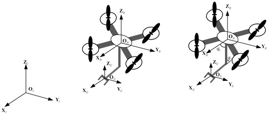
Figure 1.
Schematic diagram of the coordinate system for aerial manipulation [12].
For a quadrotor UAV, the absolute position and absolute velocity of the aerial manipulation system in the inertial coordinate system are and , respectively. The attitude of the quadrotor UAV is expressed as by the Z-Y-X Euler angle. The rotation matrix from the airframe coordinate system, , to the inertial coordinate system, , is represented by symbols, specifically by
where represents the absolute linear velocity of the quadrotor UAV with respect to the airframe coordinate system , represents the absolute angular velocity of the quadrotor UAV with respect to the inertial coordinate system , represents the derivative of attitude angle with respect to time, and represents the transformation matrix between and .
Let represent the absolute angular velocity of the quadrotor UAV with respect to the airframe coordinate system ; then, Equation (3) can be rewritten as follows:
where , is mapped to the absolute angular velocity of the quadrotor UAV with respect to the airframe coordinate system .
For the mechanical arm, is used to represent the position of the center of mass of link relative to the inertial coordinate system , which is expressed as follows:
where represents the position of the center of mass of link relative to the body coordinate system .
According to reference [13],
where represents the angular velocity of the mechanical arm link joint with respect to the body coordinate system . and are the velocity Jacobian matrix and the angular velocity Jacobian matrix of the manipulator joint , respectively; is the (n × 1) vector of the joint variables; and is the first derivative of .
2.2. Dynamic Modeling
In the dynamic modeling of the quadrotor UAV, it is usually regarded as a rigid body. The equation for flight dynamics is composed of position dynamics and attitude dynamics equations, which can be described by the Euler angle, rotation matrix, quaternion, and other methods. Dynamic modeling can adopt the Newton–Euler method, the Euler–Lagrangian method, and other traditional methods. The expressions obtained by modeling are different, but the resulting descriptions of the dynamic characteristics of objects are the same. The Newton–Euler method is easy to implement in practical applications. The Euler–Lagrangian method can easily design the controller for analyses because it gives the mass matrix, centrifugal force, Coriolis force matrix, and gravity matrix. In order to improve the stability of the aerial manipulation, the UAV is often placed outdoors during experiments. The challenges faced are also outdoor uncertainties, such as gusts, terrain, etc. These factors will affect the performance of the aerial manipulation. Therefore, dynamic modeling will have to consider these disturbances.
In this paper, the Euler–Lagrangian method is used to establish the dynamic equations for the rotor manipulator, namely,
where represents the kinetic energy of the system, and represents the potential energy of the system. Then, the system dynamics are expressed as follows:
where is the th system state variable, and is the th corresponding generalized force.
Assuming that the manipulator has n joints, the total kinetic energy of the system is the sum of the kinetic energy of the quadrotor UAV and the manipulator joints, which is expressed by the equation below:
where is the kinetic energy of the quadrotor UAV, and is the total kinetic energy of the mechanical arm joint. Furthermore,
where represents the mass of the quadrotor UAV, represents the mass of the mechanical arm joint, and represent the linear velocity of the quadrotor UAV and the mechanical arm joint in the inertial coordinate system, and represent the angular velocity of the quadrotor UAV and the mechanical arm joint in the inertial coordinate system, represents the rotation matrix from the body coordinate system to the inertial coordinate system, and and , respectively, represent the moment of inertia of the quadrotor UAV and the mechanical arm joint in the airframe coordinate system.
In combination with Equations (10)–(12), the kinetic energy of the aerial manipulation system is expressed as follows:
where is a dimension vector, and is expressed as follows:
where represents an antisymmetric matrix.
The potential energy of the aerial manipulation system is the sum of the potential energy of the joint of the quadrotor UAV and the robotic arm, and is expressed by the following equation:
where is the potential energy of the quadrotor UAV, and is the potential energy of the mechanical arm joint. In addition,
Then, the total potential energy of the system is
where represents the vector in the z direction.
Combined with the above formula, the dynamic equation of the n-joint aerial manipulation based on Lagrangian dynamics modeling is as follows [14]:
where is the positive definite inertia matrix, is the centrifugal force and Coriolis force matrix, is the gravity term vector acting on the rotor mechanical arm system, is the control torque, and is the external interference.
Additionally, is the matrix, and it is expressed as follows:
where is the element in , .
The expression for the gravity term is the following:
An exact model of the original system is difficult to obtain in practical applications and there are modeling errors in the system; therefore, , , and are often unknown and can be expressed as follows:
where , , and are the modeling errors of , , and , respectively.
Equation (19) can be rewritten as follows:
where is the model uncertainty.
Let and , and Equation (23) can be transformed into the form of state space, expressed by the equation below:
3. Design of the Disturbance Observer
The basic idea in interference observer design is to use the difference between the estimated output and the actual output to correct the estimated value. Equation (23) can be written as
In practical engineering, the compound interference is usually difficult to obtain and needs to be estimated, but there is a certain error between the estimated value of interference and the actual value. can be used to represent the estimation of interference , and the nonlinear interference observer design equation can be written as follows:
where is the estimated value of the nonlinear interference observer, is the gain matrix of the nonlinear interference observer, and is the output torque of the adaptive nonsingular fast terminal sliding mode controller. Since the above formula needs the value of the acceleration signal , which is difficult to obtain in practice, the following auxiliary function is introduced to further design the nonlinear interference observer.
First, construct the auxiliary function and let
where is the internal state variable of the nonlinear disturbance observer, and is the function vector to be designed. To avoid the occurrence of the acceleration signal , let and have the following relationship [15]:
The specific derivation can be seen in reference [15].
Then, the structure of the nonlinear disturbance observer is designed. According to (26)–(28),
Then, the disturbance observer without the acceleration signal is as follows:
Finally, the observer gain matrix and the function to be designed are created, and the estimation error of the nonlinear disturbance observer is defined as follows:
The derivative of estimation error with respect to time is the equation below:
Discuss the case of , and make the following assumption [16]: , is an unknown positive number.
The disturbance observer is designed as follows:
Take , make
where represents disturbance error.
According to assumption:
According to Equation (35):
Consider as a coefficient taking value in a limited range because , there is
Similarly, since , the lower limit of error convergence can be obtained:
The error of the disturbance observer converges exponentially into a closed sphere of finite radius: , , and a is the radius of the closed sphere. Designing properly will always make small enough.
The specific derivation can be seen in reference [16].
Since there is no prior knowledge of differential interference in the actual situation, it is assumed that is low. The characteristic change relative to the disturbance observer is slow; thus, and Equation (32) is rewritten as follows:
The nonlinear disturbance observer gain can be introduced into Equation (28) and integrated as follows:
where is the gain matrix.
To ensure the stability of the nonlinear disturbance observer, the Lyapunov function is set as follows:
Then, the derivative of is taken:
To make , suppose that there is a symmetric positive definite matrix so that
where can be obtained via the linear matrix inequality (LMI).
The two sides of Equation (43) can be multiplied by and , respectively, to obtain . If satisfies , then and Equation (43) can be rewritten as . This can be converted into the matrix according to the Schur complement theorem, and can be solved using the LMI toolbox.
4. Controller Design
The control structure block diagram of the dynamic equation of the n-joint aerial manipulation system is shown in Figure 2.
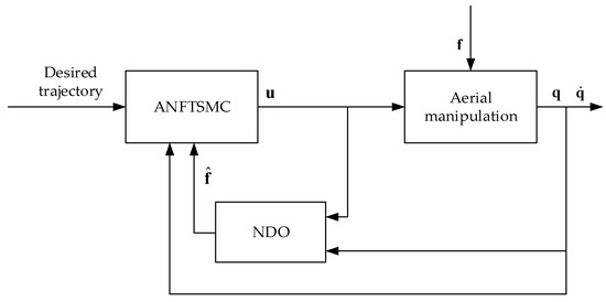
Figure 2.
Block diagram of the controller.
The controller design in this paper consists of two parts: the adaptive nonsingular fast terminal sliding mode control (ANFTSMC) and the nonlinear disturbance observer (NDO).
4.1. Nonsingular Fast Terminal Sliding Mode Controller
If and are defined, then (19) can be expressed as follows:
The derivative of the reference signal and the reference signal can be defined; then, the tracking error and tracking error derivative of the system can be expressed as follows:
The designed nonsingular terminal sliding surface [17] is as follows:
where is a normal number, is a positive odd number, and is a symbolic function; that is,
In Equation (46), the existence of the sign function will lead to chattering. In order to weaken the chattering of the control input, this study replaced the sign function with the saturation function , and the saturation function is expressed as follows:
where , is called the boundary layer. Due to the existence of the boundary layer, the saturation function improves the smoothness of the control signal and can effectively weaken the buffeting phenomenon. The greater the thickness of the boundary layer, the better the ability of the system to weaken the buffeting. However, the existence of the boundary layer will prevent the system state from reaching the zero point; instead, it will allow the system state to reach a small area around the zero point, which will cause a steady-state error. The greater the thickness of the boundary layer, the greater the steady-state error of the system. Therefore, an appropriate boundary layer to balance the contradiction between weakening the buffeting and improving the control accuracy should be selected.
Equation (46) is rewritten as follows:
Then, the derivative of the sliding surface is taken:
Additionally, introduce the robust controllers,
where .
The nonsingular fast terminal sliding mode controller was designed as follows:
where is the equivalent controller, and is the robust controller.
4.2. Adaptive Nonsingular Fast Terminal Sliding Mode Controller
In order to improve the control performance of the aerial manipulation system and accelerate the error convergence, an adaptive nonsingular fast terminal sliding mode controller is proposed [18].
Assume that [19] the total disturbance is , and that the following upper bound exists:
where , , and are positive real numbers.
Then, the dynamic Equation (23) of the aerial manipulation system can be written in the form of a state equation:
The adaptive rate is used to estimate the total disturbance, and the following adaptive nonsingular fast terminal sliding mode controller is designed:
The adaptive rate is expressed as follows:
where , , and are constants.
Assume that the system disturbance and its derivative are bounded, and .
By introducing a disturbance observer to observe the disturbance, the control law after the disturbance compensation is as follows:
Equation (50) is rewritten as follows:
After adding the disturbance compensation, it can be seen that the disturbance becomes the disturbance error , thus meeting .
5. Stability Analysis
For controllers without observers, the Lyapunov function can be selected.
The adaptive parameter estimation error is .
The derivative of the Lyapunov function with respect to time is expressed as follows:
When Equation (50) is introduced into Equation (60),
When Equations (55) and (56) are introduced into Equation (61),
where , is obtained. Based on the Lyapunov stability theory, the system will tend to be stable.
For controllers with observers, the following Lyapunov functions are designed:
Take its derivative,
If , can be obtained, then the system will finally be stable.
6. Simulation Verification
In order to verify the effectiveness and reliability of the control algorithm proposed in this paper, an aerial manipulation model with two joints was built in MATLAB/Simulink for the simulation experiments. See Table 1 [5] for the specific physical parameters of the model used in the experimental tests.

Table 1.
System parameters.
Define the expected indicator as
and the initial state as .
In the simulation process, assume that the external interference of the system is , and that the uncertainty of the model parameters is 20%; that is, , , .
The initial parameters are , , , , , , .
The simulation process is as follows: positions , , the roll angle, and the pitch angle of the quadrotor UAV make periodic sine and cosine motions; the direction rises from 0 to 6 m and remains unchanged; the yaw angle changes from 0 to 1 rad; and the two joint angles of the mechanical arm deflect from 0 to 0.5 rad. The simulation time is 10 s.
In order to verify the effectiveness of the adaptive nonsingular fast terminal sliding mode control (ANFTSMC) method designed in this study, the same test conditions were used, and simulation experiments were created to compare this method with the nonsingular fast terminal sliding mode control (referred to as terminal sliding mode) [20] and the traditional sliding mode control [21]. The convergence speed, control accuracy, and input torque were compared.
The nonsingular fast terminal sliding mode control (NFTSMC) algorithm is written as follows:
where , , , , , , and .
The traditional sliding mode control (SMC) algorithm is expressed as follows:
where , , .
As seen below, Figure 3, Figure 4 and Figure 5 show the comparison of the UAV’s XYZ position tracking, Figure 6 shows the comparison of the UAV’s attitude tracking, and Figure 7 shows the comparison of the robot arm position tracking error.
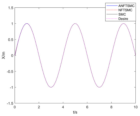
Figure 3.
Comparison of the UAV’s X position tracking.
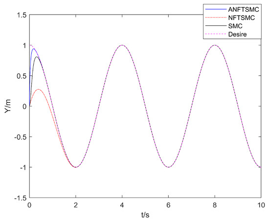
Figure 4.
Comparison of the UAV’s Y position tracking.
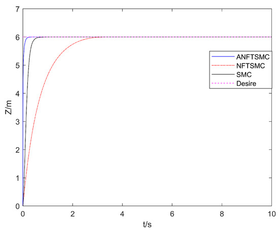
Figure 5.
Comparison of the UAV’s Z position tracking.
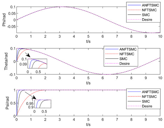
Figure 6.
The UAV’s attitude tracking comparison.
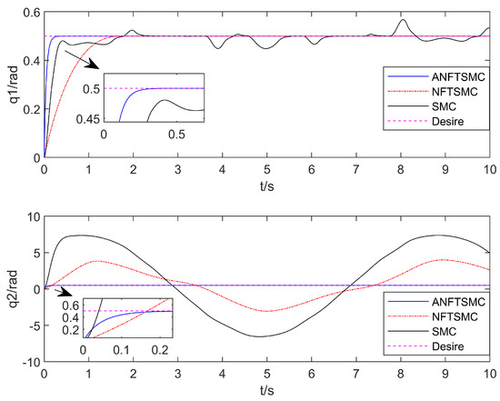
Figure 7.
Comparison of the robot arm’s position tracking.
With regard to the convergence speed: as can be seen in Figure 3, Figure 4, Figure 5 and Figure 6, the method in this paper enables the aerial manipulation system to track all the expected values on the left and right; the terminal sliding mode and the traditional sliding mode are also capable of tracking the values, but the convergence speed is slower than the method in this paper. When the system model is uncertain and there is continuous external interference, the three methods can effectively track the position and attitude angles. However, as can be seen in Figure 7, for joint angle 2, only the method in this paper can effectively track, and the curves of the other two methods are offset. In conclusion, the adaptive nonsingular fast terminal sliding mode control method with the disturbance observer proposed in this paper can track the desired trajectory faster and make the convergence occur more quickly.
Figure 8, Figure 9 and Figure 10 show the comparison of the position and attitude errors of the aerial manipulation.
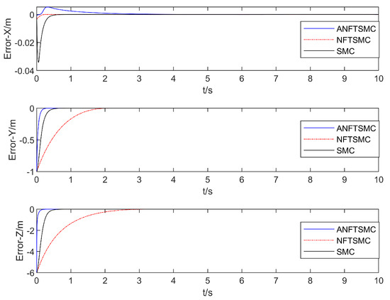
Figure 8.
Comparison of the UAV’s XYZ position tracking error.
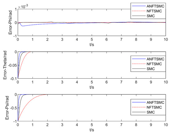
Figure 9.
Comparison of the UAV’s attitude angle tracking error.
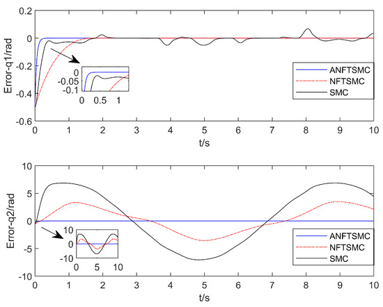
Figure 10.
Comparison of the position tracking error of the robot arm.
Regarding control accuracy: Table 2 shows that compared with those of the terminal sliding mode and the traditional sliding mode, the root mean square of the , , , , , , , and -track tracking errors in this method decreased by 57.95%, 3.34%, 19.15%, −38.96%, 2.20%, 3.35%, 2.53%, and 43.87% and by 79.58%, 3.25%, 19.04%, 48.16%, 2.30%, 3.25%, 2.51%, and 71.48%, respectively. Although the root mean square error of the roll angle in this algorithm is higher than that of the terminal sliding mode, the root mean square error values of both are less than 0.0001, which can be ignored. In conclusion, the algorithm in this paper has a smaller root mean square value for the trajectory tracking error, which illustrates that the algorithm in this paper can effectively reduce the trajectory tracking error and improve the control accuracy of the aerial manipulation system.

Table 2.
Root mean square of trajectory tracking errors.
Concerning the input torque, the following can be noted: the input torque of the controller is shown in Figure 11, Figure 12, Figure 13, Figure 14, Figure 15, Figure 16, Figure 17 and Figure 18; from left to right, these are (a) the proposed method, (b) the terminal sliding mode, and (c) the traditional sliding mode. It can be seen that the traditional sliding mode has a lot of chattering, and the terminal sliding mode has slightly reduced chattering as compared with the traditional sliding mode. However, the algorithm in this paper hardly experiences chattering due to the use of the disturbance observer, adaptive rate, and nonsingular fast terminal sliding mode surface.

Figure 11.
Control torque of the UAV in the X direction.

Figure 12.
Control torque of the UAV in the Y direction.

Figure 13.
Control torque of the UAV in the Z direction.

Figure 14.
The UAV’s roll angle control torque.

Figure 15.
The UAV’s pitch angle control torque.

Figure 16.
The UAV’s yaw angle control torque.

Figure 17.
Control torque of joint 1 of the robot arm.

Figure 18.
Control torque of joint 2 of the robot arm.
7. Conclusions
In this work, the trajectory tracking control problem of the aerial manipulation system was studied. In the case of external disturbance and parameter uncertainty, a disturbance observer was designed, which combined the nonsingular terminal sliding mode with the improved adaptive rate, and a simulation model was built to achieve stability control for the system in the case of disturbance. Finally, the Lyapunov stability theory was used to analyze the stability of the aerial manipulation system. Upon the comparison and analysis of the simulation with the adaptive sliding mode control, the results showed that, compared with the traditional adaptive sliding mode control, the controller designed in this paper could more effectively ensure the robustness of the aerial manipulation, more accurately track the desired track, and more effectively reduce the controller output chattering. However, there is still a lot of room for development in the research on aerial manipulator control. The object of study in this paper is only a two-degree-of-freedom single manipulator, which has certain limitations. Therefore, for future research, the study of double arms would in fact be closer to the current industrial needs. In addition, the control method designed in this study has only been verified by simulation, and it is hoped that it can be applied in practice in the future.
Author Contributions
All authors contributed equally to this study. Conceptualization, W.X. and L.C.; methodology, W.X.; validation, W.X.; formal analysis, W.X.; resources, L.C.; data curation, W.X.; writing—original draft preparation, W.X., B.P., and C.G.; writing—review and editing, W.X., B.P. and L.W.; visualization, W.X. and Y.L.; supervision, L.C.; funding acquisition, L.C. All authors have read and agreed to the published version of the manuscript.
Funding
This research was funded by the Opening Project of Sichuan Province University Key Laboratory of Bridge Non-destruction Detecting and Engineering Computing (No. 2021QZJ01), the Graduate Innovation Fund Project of Sichuan University of Science and Engineering (No. y2021057), and the Industry-University Research Innovation Fund of China University (No. 2021ZYA11002).
Institutional Review Board Statement
Not applicable.
Informed Consent Statement
Not applicable.
Data Availability Statement
The datasets used and/or analyzed during the current study are available from the corresponding author upon reasonable request.
Conflicts of Interest
The authors declare no conflict of interest.
Nomenclature
| Inertial reference frame | Body frame attached to the center of mass of quadrotor | ||
| Manipulator end coordinate frame | Quadrotor roll angle | ||
| Quadrotor pitch angle | Quadrotor yaw angle | ||
| Position of the quadrotor with respect to the inertial frame | Orientation of the quadrotor with respect to the inertial frame | ||
| Time derivative of Euler angles | Angular velocity of quadrotor in the inertial reference frame | ||
| Angular velocity of quadrotor in the body reference frame | Transformation matrix relating angular velocities and time derivative of Euler angles | ||
| Rotation matrix of the quadrotor with respect to the inertial frame | Transpose operator | ||
| Nominal value symbol | First joint angle with respect to the quadrotor body frame | ||
| Second joint angle with respect to the first joint | Position of the manipulator’s link i with respect to the inertial frame | ||
| Position of the manipulator’s link in body frame | Manipulator Jacobian for the linear velocities up to link | ||
| Manipulator Jacobian for the angular velocities up to link | Skew–symmetric matrix operator | ||
| The moment of inertia of the quadrotor UAV in the airframe coordinate system | The moment of inertia of the robot arm joint in the airframe coordinate system | ||
| Angular velocity of link in the inertial frame | State vector of aerial manipulation system | ||
| A symmetric and positive definite inertia matrix of aerial manipulation system dynamic | Centrifugal and Coriolis matrix of aerial manipulation system dynamics | ||
| Gravitational vector of aerial manipulation system dynamics | The error of A symmetric and positive definite inertia matrix | ||
| The error of centrifugal and Coriolis matrix | The error of Gravitational vector | ||
| The kinetic energy of the quadrotor UAV | The kinetic energy of the quadrotor UAV | ||
| The kinetic energy of the robot arm joint i | Potential energy of the of aerial manipulation system | ||
| The potential energy of the quadrotor UAV | The potential energy of the robot arm joint | ||
| Sliding surface in sliding mode control | Desired state values for aerial manipulation system | ||
| Estimation error | Lyapunov function | ||
| Uncertainty of aerial manipulation system | Gain matrix of the nonlinear disturbance observer | ||
| Function vector to be designed in nonlinear disturbance observer | The internal state variable of nonlinear disturbance observer | ||
| Gain matrix of the nonlinear disturbance observer | Identity matrix of order n |
References
- Liu, J.; Zhang, D.; Chen, Y.; Xia, Z.; Wu, C. Design of a class of generalized parallel mechanisms for adaptive landing and aerial manipulation. Mech. Mach. Theory 2022, 170, 104692. [Google Scholar] [CrossRef]
- Samadikhoshkho, Z.; Ghorbani, S.; Janabi-Sharifi, F. Vision-based reduced-order adaptive control of aerial continuum manipulation systems. Aerosp. Sci. Technol. 2022, 121, 107322. [Google Scholar] [CrossRef]
- Emami, S.A.; Banazadeh, A. Simultaneous trajectory tracking and aerial manipulation using a multi-stage model predictive control. Aerosp. Sci. Technol. 2021, 112, 106573. [Google Scholar] [CrossRef]
- Bodie, K.; Taylor, Z.; Kamel, M.; Siegwart, R. Towards Efficient Full Pose Omnidirectionality with Overactuated MAVs; Xiao, J., Kröger, T., Khatib, O., Eds.; Springer International Publishing: Cham, The Netherlands, 2020; pp. 85–95. [Google Scholar]
- Suseong, K.; Seungwon, C.; Jin, K.H. Aerial Manipulation Using a Quadrotor with a Two DOF Robotic Arm. In Proceedings of the 2013 IEEE/RSJ International Conference on Intelligent Robots and Systems, Tokyo, Japan, 20 July 2013; pp. 4990–4995. [Google Scholar]
- Song, D.; Meng, X.; Qi, J.; Han, J. Strategy of Dynamic Modeling and Predictive Control on 3-DoF Rotorcraft Aerial Manipulator System. Robot 2015, 37, 152–160. [Google Scholar] [CrossRef]
- Zhang, G.; He, Y.; Dai, B.; Gu, F.; Yang, L.; Han, J.; Liu, G. Towards Grasping Task: System and Control of an Aerial Manipulator. Robot 2019, 41, 19–29. [Google Scholar] [CrossRef]
- He, W.; Fang, Y.; Liang, X.; Zhang, P. Design and implementation of a 2-DOF aerial manipulation system. Acta Aeronaut. ET Astronaut. Sin. 2021, 42, 264–274. [Google Scholar]
- Ding, L.; Xia, T.; Kang, S.; Liu, K.; Wang, Y.; Liu, X. Adaptive robust control for a rotary-wing flight robot in hovering. J. Electron. Meas. Instrum. 2021, 35, 73–79. [Google Scholar] [CrossRef]
- Wang, Y.; Liu, L.; Ju, F.; Chen, B.; Wu, H. Sliding mode control of bionic manipulator developed for rotorcraft. J. Cent. South Univ. (Sci. Technol.) 2022, 53, 471–481. [Google Scholar]
- Liu, Y.; Zhou, Y.; Zhang, Y.; Huang, X.; Yang, J. Research on stability control of flight manipulator based on sliding mode PID. J. Nanjing Univ. Sci. Technol. 2018, 42, 525–532. [Google Scholar] [CrossRef]
- Samadikhoshkho, Z.; Ghorbani, S.; Janabi-Sharifi, F.; Zareinia, K. Nonlinear control of aerial manipulation systems. Aerosp. Sci. Technol. 2020, 104, 105945. [Google Scholar] [CrossRef]
- Pedro, S. Robotics: Modeling, Planning, and Control (Siciliano, B. et al.; 2009) [On the Shelf]. IEEE Robot. Autom. Mag. 2009, 16, 101. [Google Scholar] [CrossRef]
- Lippiello, V.; Ruggiero, F. Cartesian Impedance Control of a UAV with a Robotic Arm. IFAC Proc. Vol. 2012, 45, 704–709. [Google Scholar] [CrossRef]
- Chen, W.; Ballance, D.J.; Gawthrop, P.J.; O’Reilly, J. A nonlinear disturbance observer for robotic manipulators. IEEE T Ind. Electron. 2000, 47, 932–938. [Google Scholar] [CrossRef]
- Ming, P.; Qingxian, W.; Changsheng, J.; Lu, C. New Fast Terminal Sliding Mode and Its Application to Near Space Vehicles. Acta Aeronaut. Astronaut. Sin. 2011, 32, 1283–1291. [Google Scholar]
- Liu, H.; Zhang, T. Neural network-based robust finite-time control for robotic manipulators considering actuator dynamics. Robot. Comput. Integr. Manuf. 2013, 29, 301–308. [Google Scholar] [CrossRef]
- Xu, B.; Song, G.; Wang, C.; Cao, G. Adaptive Non-singular Fast Terminal Sliding Mode Control of Manipulator. Electron. Opt. Control. 2021, 28, 46–50. [Google Scholar]
- Qiao, L.; Zhang, W. Adaptive Second-Order Fast Nonsingular Terminal Sliding Mode Tracking Control for Fully Actuated Autonomous Underwater Vehicles. IEEE J. Ocean. Eng. 2019, 44, 363–385. [Google Scholar] [CrossRef]
- Hua, Y.; Sun, W.; Chi, B.; Guo, X.; Liu, G. Study on nonsingular fast terminal sliding mode control. Syst. Eng. Electron. 2017, 39, 1119–1125. [Google Scholar]
- Liu, J. Sliding Mode Control Design and Matlab Simulink; Tsinghua University Press: Beijing, China, 2012. [Google Scholar]
Disclaimer/Publisher’s Note: The statements, opinions and data contained in all publications are solely those of the individual author(s) and contributor(s) and not of MDPI and/or the editor(s). MDPI and/or the editor(s) disclaim responsibility for any injury to people or property resulting from any ideas, methods, instructions or products referred to in the content. |
© 2023 by the authors. Licensee MDPI, Basel, Switzerland. This article is an open access article distributed under the terms and conditions of the Creative Commons Attribution (CC BY) license (https://creativecommons.org/licenses/by/4.0/).