1. Introduction
Non-Terrestrial Networks (NTN), including drones and nano-satellites, bring considerable solutions for collecting data in the future internet of things. Indeed, wireless sensor networks (WSNs) have attracted exponential research growth due to their broad range of applications ranging from military [
1], environmental [
2,
3] to agriculture [
4,
5]. The main function of a WSN is to collect as much data as possible and transmit it to the data center, where it is observed, analyzed and processed. Multi-hop is a widely accepted option to improve data collection in applications where sensors are statically deployed and battery-powered. However, it brings sensors that act as intermediate nodes to die faster than simple nodes because they consume a lot of energy to relay messages. As a result, mobile sinks are introduced into WSN to balance network energy consumption by moving between sensors. The mobility of the sink brings new issues including dynamic topology, synchronization, network lifetime, etc. [
6,
7,
8]. In existing research, most of the network typologies utilize static or quasi-static (move on the ground at a low speed) nodes. However, it is hard to be implemented in harsh terrains, such as snowberg or forests, which are dangerous for humans. In such applications, Unmanned Aerial Vehicles (UAVs) are more widely accepted due to their great flexibility and no need to involve humans.
UAVs can be drones, quadcopters, gliders, and balloons. Due to different application requirements, they could be equipped with various sensors, e.g., cameras, super-sonic sensors, etc. UAV-enabled WSN (U-WSN) comprises an air platform and a ground platform. The air platform could be composed of several UAVs. UAVs should be well controlled to keep a safe flight distance and a proper distance with the ground control center to make them under control. The ground platform could be composed of many sensor nodes, base stations, and data center according to applications. In applications, e.g., UAVs are dispatched for aerial photography, no ground sensors needed to be deployed. Thus, the ground sensors are not mandatory in a U-WSN.
The design of U-WSN applications requires wireless networking techniques. Although many protocols and algorithms have been proposed for traditional WSN applications, they can no longer meet up with the unique features and application requirements of U-WSN. The main differences between WSN and U-WSN are outlined below:
The topology of a U-WSN changes more frequently.
The sensors are prone of being out of the range of the UAV if they have high relative velocities.
The scale of the area of a U-WSN can be several orders of magnitude higher than the scale of a WSN.
The UAVs are very limited in power compared to the ground sensor nodes and the base station.
The UAVs need to be dispatched to maintain a safe flight and other issues.
Many researchers are currently engaged in developing schemes that fulfill these requirements. This paper presents a review of UAV-centric architectures, applications, and open issues. We aim better to understand the current research issues in this field. We also attempt to investigate design constraints and outline specific tools to meet the design objectives.
The main contributions of this paper are summarized as follows:
analyze the performance and the capabilities of the UAV, based on which, we summarize the U-WSN applications.
refine the UAV functionalities as a communication node in a U-WSN.
compare and draw the network architecture and the standard technologies in U-WSN.
evaluate the main factors which influence the U-WSN design.
review and analyze the open issues and challenges in U-WSN.
The organization of this article is as follows: In
Section 2, summarize the performance and capability of the UAV, and the relative applications of the U-WSN, and the functionalities of the UAV as a communication node.
Section 3 analyzes the factors that influence the U-WSN design.
Section 4 presents open issues and challenges in U-WSN.
Section 5 gives a conclusive remarks of this work. Finally,
Section 6 concludes this work.
2. Applications of U-WSN
Using UAVs is much more diverse in our daily life because of its significantly deployment possibilities. Applications of U-WSN may either be traditional ones such as military monitoring and reconnaissance, environmental disaster detecting and industrial control or completely new application types such as smart city.
There are extensive surveys that have been done on the applications of U-WSN. For example, the authors in [
9] provide a review on the task using mobile robots. Shakhatreh et al., provide a survey on civilian applications [
10]. These research mainly focus on the application fields when studying the application of the UAV. In this section, we will study U-WSN applications through the performance and the capabilities of the UAV.
2.1. UAV Categorization
UAV is known as an aircraft or a drone without human on board. Humans control the UAV in a variety of ways, such as ground control center, pre-programmed flight trajectory and more complex and autonomous systems. Due to its different performances, capabilities and restrictions, the UAV encompass a wide range of different platforms.
One of the detailed and widely used schemes has been proposed in [
11], as shown in
Table 1. In which, the UAVs are classified based on the mass, range, altitude, and endurance. Moreover, another scheme based on Mean Take off Weight (MTOW) and the ground impact risk has also been proposed [
11], as illustrated in
Table 2.
2.2. Applications of U-WSN
Hereafter, we summarize and group the applications of U-WSN as in
Table 3. If we consider the area where the sensors are deployed, the applications can be classified as in
Table 4.
In aforementioned applications, both UAV and WSN play different roles and have different functionalities. We will detailed the functionalities of UAV in the next sub-section.
2.3. Functionalities of UAV as a Communication Node
In WSN applications, one of the objective is to obtain meaningful information through sensors deployed in the region of interest. Traditionally, the data gathering issues were implemented in multi-hops in which the sensors that are closer to the base station will selected as the relay nodes for those sensors that deployed far away from the base station. As a result, these relay nodes consume energy much faster than other nodes. As the network connectivity depends on these relay nodes, this will result in a shorter network life-time. To address these issues, mobile vehicles were introduced.
Generally, it has limited conditions, such as limited velocity, and obstacles due to actual movement environment, when the mobile vehicles move on the ground. It would be a huge challenge if the traditional mobile vehicles are used in specific applications that are dangerous for human participation. Thus, UAV which has high extensive and flexible and do not need human on board, is a better choice in these similar applications. In this section, we will analyze and study the functionalities of UAV when it works as a communication node in WSN.
As previously described, UAV has been extensively applied in many areas. In this section, we analyze the existing applications and propose the main functionalities of the UAV in WSN.
2.3.1. Maintaining Connectivity and Relaying
Maintain connectivity is one of the key problem in wireless networks. The failures occurrence leads to the disconnect of the networks. The solution of such issues is to provide a reliable multi-hop path to maintain the connectivity through other kinds of nodes, such as mobile vehicles. However, it cannot maintain the wireless network connectivity all the time. That is because the mobility of the mobile sink, based on which a node is within the transmission range of the mobile sink at this moment may out of its range at next moment. In addition, the motion trajectory of the mobile sink is also restricted by the network deployment. Thus, UAV, which trajectory could be predefined or randomly, is introduced to work as mobile sink.
Extensive investigations have been conducted on maintaining connectivity in the context of U-WSN. Research in [
3] address the city-scale video monitoring in WSNs. Multiple UAVs ride buses in a noisy 3-D environment were considered. The UAVs could recharge through moving bus; thus, it could maintain the connectivity of the network. However, their study addressed on static objective nodes. In our previous works [
17,
18,
19], we address the dynamic wireless networks in which both the mobility of collectors and nodes were considered. The simulation results in [
18] present that the moving of UAV can maintaining the connectivity of the wireless network. The sensor nodes that are without the transmission range of the base station could have an opportunity to communicate with the UAV through create connection path to the connected neighbours.
However, our previous works fail to consider the case that the UAV and the sensor moving in opposite directions. In
Section 4.2, we not only study the mobility of the UAV and the sensor, but also consider the case where they move in different directions, and the relationship between them also considered.
In
Table 5, we summarize and compare the use of UAV for maintaining connectivity in wireless networks.
2.3.2. Data Collection
In traditional data collection protocols, sensors were usually assumed to be static and densely deployed. Sparse and mobility were not considered because they cannot maintain connectivity of the network. Thus, the nodes may not be connected through multi-hop paths. After the introduction of mobile nodes, how to collect data from the mobile nodes becomes a new challenge.
Data collection has been addressed extensively in the literature. In [
32], the authors proposed an energy conservation scheme to extend the network lifetime, and the data collecting time is extended accordingly. In reference [
24], the authors attempt to make full use of integrating small-scale UAV in a ground wireless network for information collecting and environmental monitoring and surveillance. The cost-reducing and energy-saving were conducted through using small-scale UAVs.
In [
25], the authors address the data gathering problem of how to efficiently utilize the battery power for the maximizing data collection performance in rechargeable WSN. The rechargeable sensor network can provide enough energy to maintain the system connectivity. In [
26], the authors propose the optimal speed control of the UAV which could helps the system to collect data efficiently. Both of them are based on a single UAV. The authors in [
27] address the data collection issue through multi-UAVs, in which both the packet received ratio and packets tracking ratio were evaluated. However, the fairness and collisions between UAVs are failure to considered in this work. In addition, this is one of the main contributions that the authors in [
22] have done. The authors concentrate on the problem of data gathering from scattered sensors through integrating several UAVs in the context of large scale sensor networks. A heuristic algorithm based on a column generation approach was proposed and the results perform well.
The main idea of these research is to extend the data collection time through extending the network life time. They pay little attention on the impact of the network topology on data collection. In U-WSN, the dynamic topology has a critical influence on the connectivity of the wireless network. It will directly affect whether a route is created between two nodes and the endurance of the connection.
However, most of existing works address the static network topology. The authors concentrated on the dynamic topology in [
17,
18,
19], both the mobility of the UAV and sensors are considered. The authors fail to present all the relationships between the mobility and the data collection because of space limitations. In
Section 4.2, we address the impact of the dynamic topology on the connection. In
Table 5, we provide a summarisation and comparison of using UAV for data collection in the existing applications.
2.3.3. Localization
Location-based services in variety of applications, such as weather forecasting, traffic monitoring, smart home [
33] and rescue application. Global Positioning System (GPS) [
34] is a solution in such applications. GPS works well on localization when the applications are implemented outdoor. It is better for the GPS to be used far enough from buildings or obstacles otherwise GPS signals become unreliable. However, GPS has high power consumption, especially in large scale networks, and poor performance when applied indoors. Thus, a large number of works have been done to optimize the location-aware performance.
Various types of categories of existing localization methods have been introduced according to different standards, range-based and range-free, coarse-grained and fine-grained, cooperative and cooperative-free, networking centric positioning and self-positioning. Among these classifications, the Range-Based and Range-free algorithms are the typical one according to whether to use range information. Typical Range-Based algorithms such as Time of Arrival (ToA), Time Difference of Arrival (TDoA) and Received Signal Strength (RSS). Range-free methods calculate the location information from the connectivity information.
There is a huge scope of application offline training for localization. Thus, it is critical for the localization mechanisms to implement the training step for taxonomic hierarchy in the infrastructure of internet of things. The localization algorithms are classified into two categories, self determining and training dependent methods, if we take into account the internet of things scenario.
Localization methods with mobile nodes are the best solutions regarding these issues. Vehicles moving in the interesting area and broadcasting ’beacons’ messages, through which vehicles can self-localize via combining with appropriate methods. Nodes that have received the ’beacon’ messages are within the transmission range of the mobile vehicles. Through combining with proposed technologies, the sensor nodes can provide an estimation about their locations after enough ’beacons’ messages are received. The vehicle-aided localization algorithms are classified into two categories, static vehicle-aided localization and mobile vehicle-aided localization. In static vehicle-aided localization algorithms, e.g., in [
35], the localization accuracy depends on many factors, the number of vehicles, the deployment and the trajectory of the vehicles, etc. It can be predicted that uniform deployment in high densely will bring a high localization accuracy. However, it also leads to high hardware cost and energy consumption. The UAV, which moves at a high speed and has high flexibility, works as a mobile vehicle which is the best choice in such applications.
In the context of U-WSN, the authors in [
28] address the issue of how to achieve three-dimensional localization using a UAV. In this work, sensors are deployed in the monitoring area without equipped a GPS while UAV is equipped with a GPS. UAV flies over the area and broadcasts ’beacon’ messages which include the geographical information of the UAV. The nodes that received the ’beacon’ messages are able to estimate their geographical positions through combing with appropriate technologies. However, it is not a real-time algorithm. The authors in [
29] proposed a real-time localization algorithm using Extended Kalman Filter which is based on time difference of arrivals. The proposed algorithm works well on the estimation of sensors positions. In
Section 4.2, we focus on the dynamic topology wireless network and provide a definition on the relationship between the UAV and the mobile nodes, based on which the nodes positions could be well estimated. In [
36], the authors provide a summary on mobility-assisted localization algorithms in wireless networks.
In
Table 5, we summarizes the use of UAV for localization in the existing applications. Thereafter, the functionalities of UAV as a communication node are detailed in
Table 5.
3. Factors Influencing U-WSN Design
A U-WSN design is influenced by many factors, including architecture of U-WSN; relative motion between the UAV and the Sensors; fault tolerance; scalability; production costs; operating environment; hardware constraints; transmission media; and power consumption. These factors are addressed by many researchers as surveyed in this paper. However, none of these studies has a full integrated view of all factors that are driving the design of sensor networks and sensor nodes. These factors are important because they serve as a guideline to design a protocol or an algorithm for sensor networks. In addition, these influencing factors can be used to compare different schemes.
3.1. Architectures of U-WSN
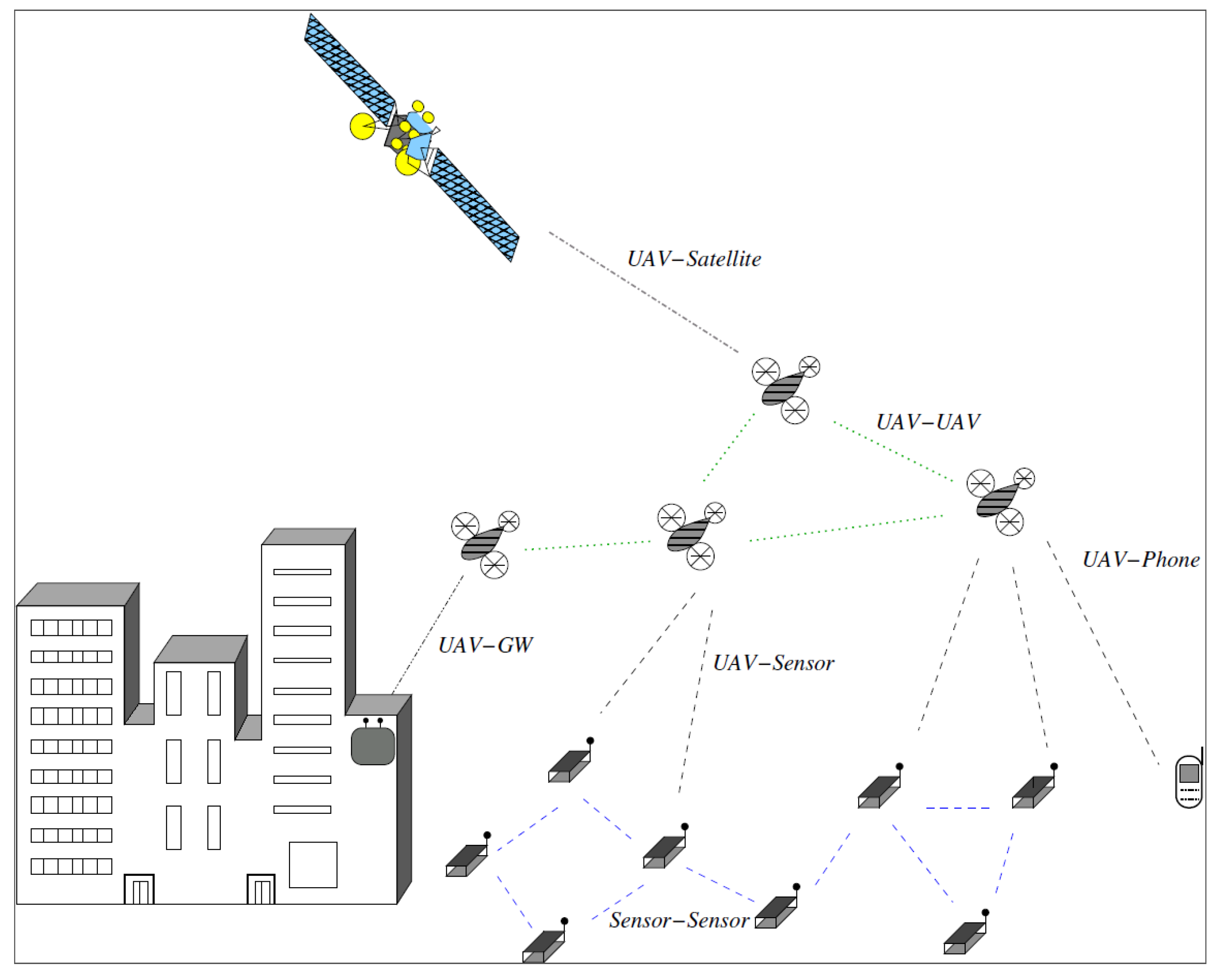
In the architecture design, the main objective is to impose few requirements to the execution capabilities of the UAV. Basically, the UAV is able to move to a given location and activate their payload when required. Then, according to different applications, UAV is integrated in different architectures. The global picture of the main architectures in U-WSNs is shown in
Figure 1. The general architecture could be mapped to various specific scenarios. In the following, we introduce the links and the relevant technologies with their application fields in
Figure 2.
3.1.1. Sensor-Sensor Link (S-S)
The communication between sensors is the basic one included in other links. A low energy and data rate protocol can be used. The standard IEEE 802.15.4 [
37], along with the corresponding upper layers which are compliant with the ZigBee [
38] protocol stack, is typically used at this link layer. Generally, the data-rate is less than 1 Mbps.
3.1.2. UAV-Sensor Link (U-S)
In the link between UAV and sensor, the UAV usually acts as a mobile sink. The distance between the UAV and a sensor is ranging from several meters to hundred meters. In the case of close range, the U-S links could apply the technologies as in S-S link. The connection between UAV and sensors is able to use the IEEE 802.15.4 (ZigBee) and IEEE 802.11ah (WiFi) [
39] protocols. These protocols have the medium range that could achieve several hundred meters.
3.1.3. UAV-Smart Phone Link (U-SP)
In some applications, the UAV is connected to smart-phone in order to collect data from the phone. The commutation range between them is medium. Thus, the U-SP link basically uses the medium range protocols such as IEEE 802.11ah (WiFi) and IEEE 802.16p (WiMAX), which are adapted for machine to machine communication. Adaptations of LTE-Advanced (LTE-A) are also experimented [
40].
3.1.4. UAV-GateWay Link (U-GW)
Similarly to U-SP, the connection between UAV and gateway used to collect information. Thus, their communication range are at the same level. The U-GW link use medium range protocols such as IEEE 802.16p (WiMAX) for real-time data delivery and LTE/LTE-A for transmitting large data (e.g., video) in real-time monitoring.
3.1.5. UAV-UAV Link (U-U)
In this category, the data transfer between UAVs, and the UAV create link with UAV. The protocols, e.g., IEEE 802.11, IEEE 802.16p (WiMAX), with medium range can be used to achieve the connectivity between the UAVs. In real-time applications, the U-U links can apply LTE/LTE-A.
3.1.6. UAV-Satellite Link (U-SL)
In some applications, the UAV is connected to satellite. The communication range is long. To achieve the long distance connectivity, the Random Access (RA), hybrid schemes and Demand Assignment (DA) schemes are usually used. In
Figure 2, we provide a summary and comparison of their technologies and applications.
3.2. Scalability
The number of sensor nodes may be in the order of hundreds or thousands, or reach an extreme value of millions. The network topology is dynamic The new schemes must be able to work with this number of nodes and utilize the high density of the network. The density gives by the number of nodes within the transmission radius of each node in region
A, and it can be calculated according to [
41] as
where
N is the number of sensors in region
A, and
R is the radio transmission range. In general, the density can be as high as 20 sensor nodes per m
[
42]. The node density depends on the application. For the vehicle tracking application is around 10 sensor nodes per region [
42]. A home may contain around two dozens of home appliances containing sensor nodes [
43], but this number will grow if sensors are embedded into furniture and other miscellaneous items. For human motion tracking application is around 5 nodes per 5 × 5 m
[
7]. For habitat monitoring application, the number of sensor nodes ranges from 25 to 100 per region [
44].
3.3. Fault Tolerance
Some sensor nodes may fail or be blocked because of power exhaustion, the UAV’s motion, or environmental interference. The failure of sensor nodes should not affect the overall task of the U-WSN. This is the reliability or fault tolerance issue. Fault tolerance is the ability to sustain sensor network functionalities without any interruption due to sensor node failures [
45,
46]. The reliability
or fault tolerance of a sensor node is modelled in [
46] using the Poisson distribution to capture the probability of not having a failure within the time interval (0,
t):
where
and
t are the failure rate of sensor
and the time period, respectively. Note that protocols and algorithms may be designed to address the level of fault tolerance required by the applications. If the studied environment has little interference, then the protocols can be more relaxed. For example, if sensor nodes are being deployed in a house to keep track of humidity and temperature levels, the fault tolerance requirement may be low since this kind of sensor networks is not easily damaged or interfered by environmental noise. On the other hand, if sensor nodes are being deployed in a battlefield for surveillance and detection, then the fault tolerance has to be high because the sensed data are critical and sensor nodes can be destroyed by hostile actions. As a result, the fault tolerance level depends on the application of the U-WSN, and the schemes must be developed with this in mind.
3.4. Power Consumption and Network Lifetime
The wireless nodes and the UAV are powered by battery which has limited power source. Both the lifetime of the sensors and the UAV show a strong dependence on the micro-electronic device lifetime. Therefore, power conservation and power management take on additional importance. It is for these reasons that researchers are currently focusing on the design of power-aware protocols and algorithms for sensor networks.
The main task of a sensor node in a sensor field is to detect information and forward them. In addition, the main task of the UAV is to load sensors or devices. Hence, the power consumption of the sensors includes three phases: sensing, communication, and data processing. The main power consumption of the UAV is the movement consumption [
7]. It costs a lot when it flying at an altitude [
7]. In addition, there is a big gap between the energy consumption during different UAVs [
7]. The sensing unit and the data processing are the same as in traditional WSN [
47]. For the communication unit, it was noticed that, in a U-WSN, the communication contains two phase, the communications between sensors on the ground and the communications between the on-ground sensors and the air sensors that deployed in the UAV. In addition, the communications between the ground sensors is able to adopt the model as presented in [
47]. In this section, we will focus on the air-ground communication.
3.4.1. Power Consumption during Air-Ground Communication
The Signal-to-Interference-and-Noise Ratio (SINR) is used to measure the achievable throughput and link quality. Suppose that, the SINR is denoted by
, then,
where
is the interference power summing at the receiver,
is the receiver noise power,
is the received power from the serving transmitter. For a particular application, in order to achieve the required throughput, the SINR is set at a given throughput (denoted by
) through adjusting the transmitter power. The energy consumption involved in the process of delivering a message (from a ground node) towards an aerial collector over a session interval
, can be given as the following [
48],
where
is the average aerial interference power, and
is the platforms noise power. Generally, the main focus is in the energy consumption of the sensor nodes, and it assumes that the network is not constrained by the possible limitation in the aerial platforms energy. Accordingly, its energy consumption is not account. Then, the total energy consumption is obtained by
3.4.2. Network Lifetime
Network lifetime is a key design consideration for battery-powered U-WSNs. There exist number of research focus on the lifetime maximization issues [
49,
50] or on the prediction of the remaining lifetime [
51,
52]. Other research focus on the energy-efficiency issues so as to extend the network lifetime [
53,
54,
55,
56], and the trajectory planning of the UAV is one of the most consideration among these schemes [
30,
57,
58]. Although a number of studies have been done for network lifetime, U-WSN still face some issues, e.g., the collisions and re-transmissions during communications, which cannot fully avoided in applications that degrade the lifetime.
3.5. Security and Regulation
Security and regulation of the data collected from a U-WSN, either while stored inside the UAV or during their transmission from the UAV to a gateway, is a major unsolved concern. Furthermore, as thousands of businesses could receive clearance to fly drones in the near future, UAVs will face with various security issues such as loss of data, authentication, access control, and intrusion attacks. In U-WSNs, security solutions are required for data confidentiality, authentication and integrity at low cost.
Moreover, there are still many regulation issues to be resolved in the coming research. Indeed, there are many requirements from the governments to regulate where the drones fly and what is done with the torrents of data collected from aerial surveillance [
59]. In fact, numerous civilian drone manufacturers claim that the main barrier in U.S. and Europe is not the technology, but the regulation. For instance, the U.S. FAA (Federal Aviation Authority) provide some basic regulations and restrictions of the airspace that will govern who can fly drones in the United States and under what conditions. A standard that is formulated by 2016 will permit unmanned aircraft systems (UAS) to interoperate with manned aircraft using an “electronic means” to see and avoid potential aerial disasters. Due to the UAV is flying in the same national airspace, it is crucial for the world to comply with a same safety regulations and restrictions.
4. Open Issues and Challenges
This section summarizes and discusses the open research issues and challenging future directions. L. Gupta et al. provide a survey on important issues in U-WSN [
60].
4.1. Synchronization Issues
The synchronization issue was a thorny subject in U-WSN, considering the limited communication time. In the past, many synchronization algorithms have been investigated to keep the synchrony of networked systems. The perfect time synchrony, Time-Diffusion Protocol (TDP) [
61], was proposed by Su and Akyildiz. In the synchronization process, the TDP applies an iterative and weighted averaging mechanism built on the collected messages from the whole network. In reference [
62], the authors through enhancing the TDP scheme to adapt to the particular applications (e.g., tracking and surveillance) that require global time synchronization and fault-tolerance. However, most of these research are based on traditional wireless networks. In the context of U-WSN, especially in dynamic topology, the beaconing mechanism is usually used for the network synchronization [
17,
18,
19,
63,
64]. In [
65], the authors provide a survey on the synchronization in U-WSNs.
4.2. Relative Motion between the UAV and the Sensors
Both UAVs and targets are moving in U-WSN applications, such as animals monitoring. The topology of the network changes as the node and the UAV move. At this point, one node is within the range of the UAV, while at another time, it may be outside the transmission range. Thus, mobility directly affects the connectivity of the network. It has a significant impact on the data transmission performance of the network.
The duration that the mobile node is within the transmission range of the UAV has an essential impact on the performance of the network, which is defined as contact duration [
7,
17,
18,
19]. However, it only considers the case of mobile nodes and the same mobile direction as the UAV, the static case and opposite mobile direction with the UAV are not considered. In the following, we will provide a complete definition.
4.2.1. Contact Duration between the UAV and the Sensor
In U-WSN with mobile sensors, the node has an opportunity to communicate with the UAV when they are within range of each other. The link duration is named as
contact duration [
7,
17,
18,
19]. As the "one UAV and one sensor" is the min-unit in U-WSN, we take this scenario where the UAV moves along a predefined path to maintain the network connectivity, for example, to calculate the
contact duration (which is denoted as
in this article).
According to the existing research, we refined the scenario into two categories: (a) both the UAV and the sensors move along a straight path, and (b) they move along a curved path. The other cases, e.g., the “trajectories” of the UAV and the sensors have some intersections, still need further study.
- (a)
Straight Path
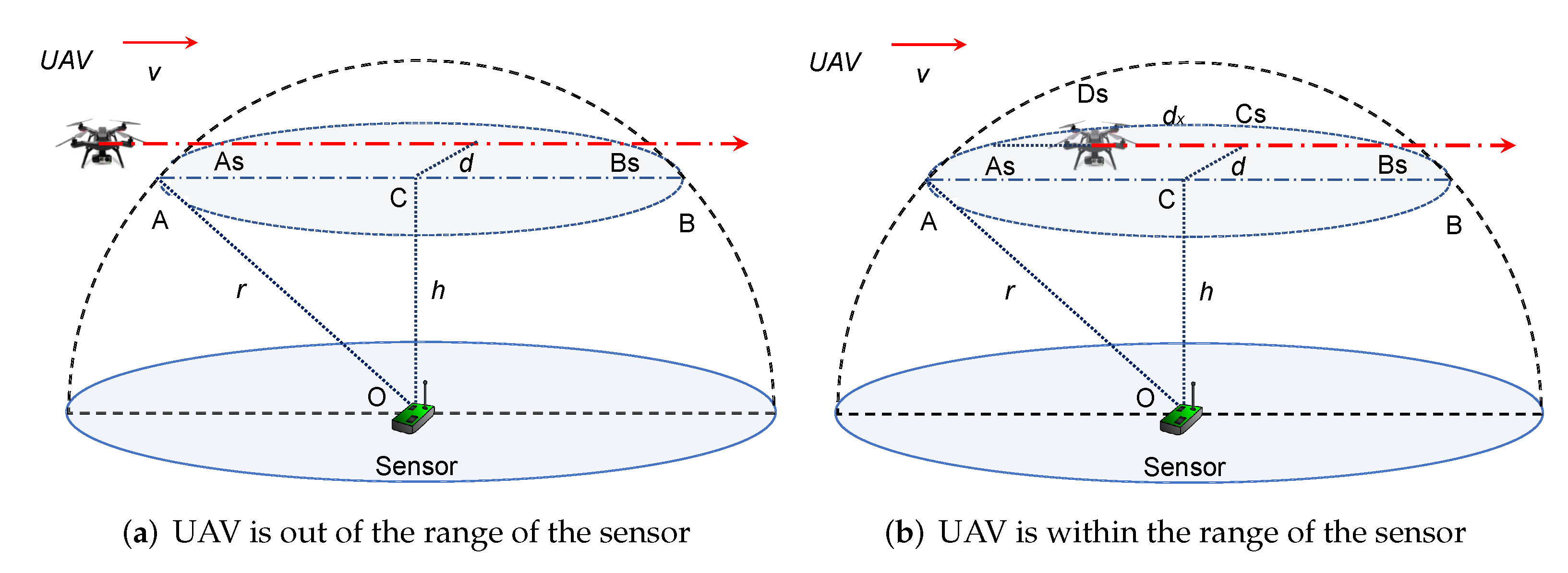
When the trajectory of the UAV is a straight path, the scenario can be further refined as: sensor is static (
Figure 3), sensor and the UAV are move at the same direction (
Figure 4), and in the opposite direction (
Figure 5).
The relative movement distance between sensor and the UAV is denoted by . UAV fly at a height h with constant velocity v. The range of the sensor is denoted by r. The original distance between UAV and node is . Then, we will discuss the calculation of the contact duration time as follows:
The node is static (
Figure 3). In this case, the relative velocity between the node and the UAV is
v. The relative movement distance between them is
, i.e.,
when the UAV is out of the range (
Figure 3a). In
Figure 3b, when the UAV is within the range of the node,
, i.e.,
The
contact duration between the UAV and the static node,
can be given by,
This is based on an assumption that the flying height of UAV is smaller than the range of the node (
) and the UAV is out of the range of the node in the beginning (
). The relative movement distance will be different if their topologies are changed (as illustrated in
Figure 4 and
Figure 5).
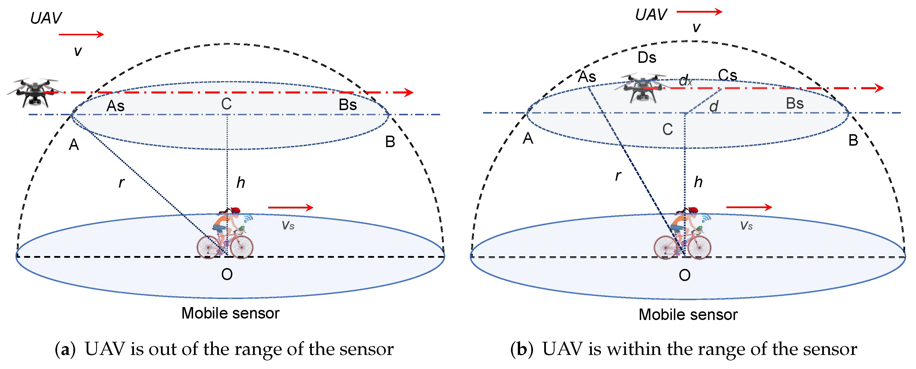
The node and the UAV move at the same direction (
Figure 4). The sensor velocity is
. The contact duration time depends on the original deployment of the UAV if the sensor and the UAV have the same speeds (
). The relative velocity between the node and the UAV is 0. Let the moving time and distance of node are
T and
L respectively. The relative movement distance between the UAV and the sensor is
when the UAV is out of the range of the UAV (
in
Figure 4a).
when the UAV is within the range of the node (
in
Figure 4b).
When
, similarly to static case, the relative distance between them can be given by,
Then, according to Equation (
8) and
Figure 4b, the
between the UAV and the mobile sensor (moving at the same direction), can be given as in,
where
.
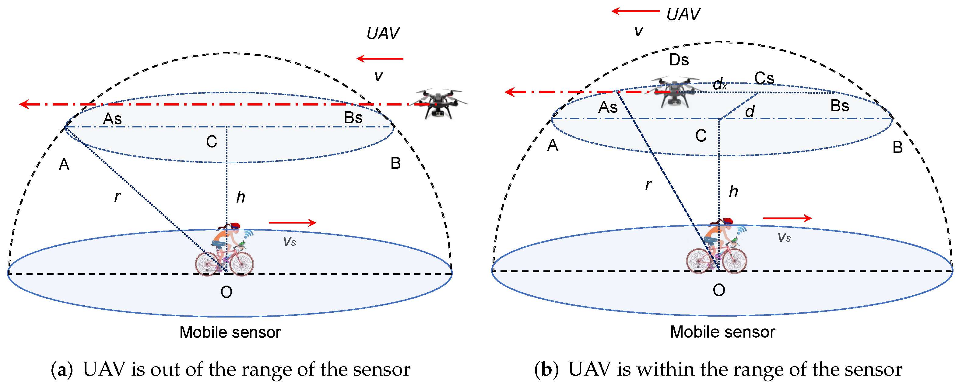
The node and the UAV move at opposite direction (as shown in
Figure 5). Similarly to the front case, the relative movement distance depends on the dynamic topology. Hence, it can be given by,
Then, the
between the UAV and the sensor (moving at the opposite direction) can be calculated by,
As shown in
Figure 3,
Figure 4 and
Figure 5,
achieves the maximum when the UAV flies on the top of the node. This conclusion is corroborated in Equations (
8), (
10) and (
12). The longer the
, the higher opportunity for the sensor to communicate with the UAV.
- (b)
Curve Path
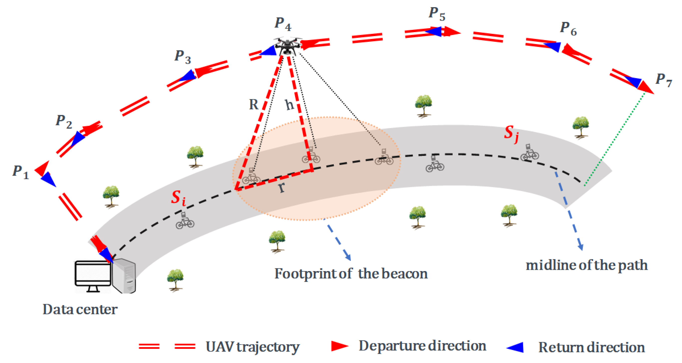
When the trajectory of the UAV is a curve path (
Figure 6), the contact duration is obtained through a beacon based prediction mechanism [
31].
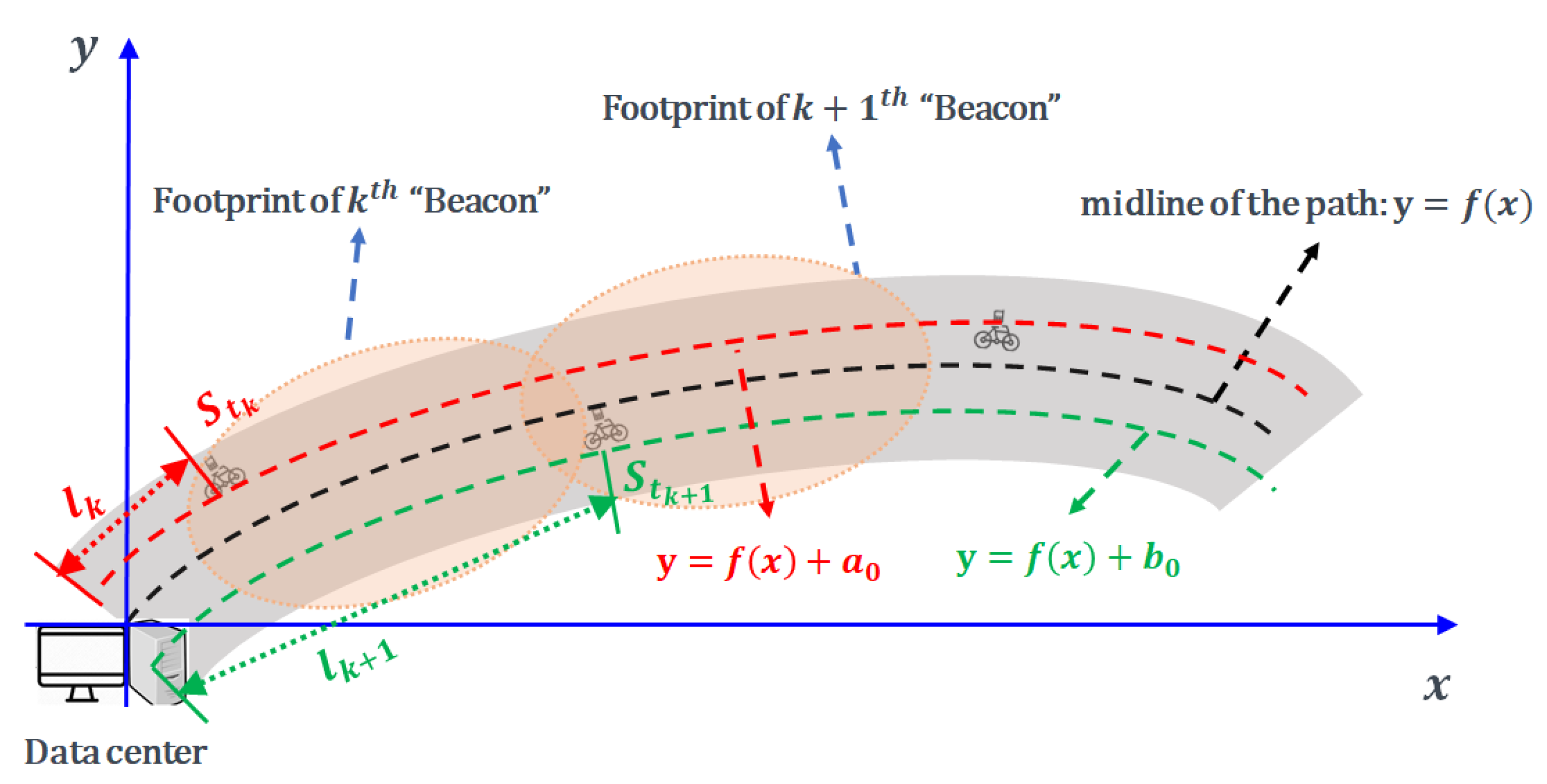
The midline of the pre-defined path is
(
Figure 7). At
, the UAV sends a beacon message to its coverage, and
S receives it and successfully sends the join message to the UAV. The precise location and speed of the
S which are recorded in join message are obtained by the UAV. The location coordinates is denoted by
. The vehicles are supposed to mobile on a flatland and it assumes that the altitude changes are negligible. The distance between
S and the midline of the path is denoted by
(
Figure 7). Without loss of generality, we assume that the
S moves along a line which is given by
before the next beacon coming. This assumption is based on an estimation that the influence brought by the lane change of bicycles is negligible compared to the path length.
Suppose that, the
th beacon is sent at
(then, the
=
). Then, the coordinates of
S at
(
) is given by,
where
is the curve length of
when
. Accordingly, the coordinates of the UAV at
can be obtained through,
Let
be the
remaining contact duration of the node
S and the UAV at
. It means that the
S will out of the range of the UAV after
, and it can be obtained through,
with a boundary conditions
where
and
R is the transmission range of the UAV.
4.2.2. Summary and Insight
Through reviewing the relative motion between the UAV and sensors, the contact duration between the sensor and the UAV is one of the key factor in the U-WSN applications. The longer the contact duration, the higher opportunity for the communication between the sensor and the UAV. Conversely, the shorter the contact duration, the lower opportunity of the communication between them. Thus, the data transmission of the network can be better improved, if the contact duration is considered [
17,
31].
Furthermore, the fairness of the network can be enhanced if the contact duration is considered when designing the routing protocols [
45] or MAC protocols [
19].
4.3. Trajectory Planning of the UAV
As aforementioned, mobile vehicle based technologies are effective methods addressing localization issue because of its mobility and flexibility. Path planning is object to improve the localization accuracy with a best possible trajectory of the UAV. Proper path planning can guarantee good coverage of the whole sensing field as well as keeping the minimum path length. Study in [
66] is an application to UAV path planning. An adaptive operator quantum-behaved pigeon-inspired optimization algorithm along with logistic mapping method were proposed in [
66] for the application to UAV path planning. A comparison result presents that the performance of their proposed algorithm is better than parts of the existing algorithms in terms of convergence and accuracy. Indeed, according to different applications, many investigations with different objective functions and optimization methods have been done (we summarize them in
Table 6).
Moreover, according to whether there is interaction between UAVs and nodes, path planning of U-WSN has two categories. First is static path planning in which the path is predefined and second is dynamic path planning in which the path can be changed. The existing algorithms are summarized and compared in
Table 7.
4.3.1. Static Path Planning
In static case, the trajectory for mobile vehicles is determined in advance. Vehicle moves along the pre-determined trajectory strictly. The simplest case is that the vehicles move in Lines [
70]. The vehicle moves in a predefined line and broadcasts gradient signals to localize the unknown node. The trajectory is a x-rays. Based on this, the algorithms can be SCAN, DOUBLE SCAN, and HILBERT [
71]. In SCAN algorithm, the vehicle moves in one direction while it moves in both directions in DOUBLE SCAN method. In HILBERT SCAN scheme, the vehicle moves in the Hilbert pattern. They all have the same objective that is to maximize the network coverage, even in the corner. It can be noticed that some areas are visited frequently because of the linearity of the trajectory. Thus, curves were introduced. Circle and s-curve [
72] are the critical methods to reduce localization col-linearity [
72] (in statistics, the co-linearity refers to the fact that the explanatory variables in the linear regression model are distorted or difficult to estimate accurately due to the existence of precise correlation or high correlation between the explanatory variables. Thus, in the localization mechanism, the localization could be well estimated if the col-linearity could be reduced.). However, this types of scan leave the corner of the region. Thus, mobile anchor node centroid localization (MACL) algorithm [
73] was introduced. In MACL, the mobile vehicle traverses the interesting area following a spiral trajectory and periodically broadcasting beacon packets which contain its current position. More algorithms and their characteristics are summarized and compared in the
Table 7.
4.3.2. Dynamic Path Planning
The static path planning algorithm works well when the unknown nodes are assumed to be uniformly deployed. However, it may not be a better solution when the nodes are deployed disarray. Due to the disarray deployment, it spends a lot of localization time and moves long path if the system use the static path planning algorithms. Some researchers concentrate on the work of dynamic case to fully utilize the distribution information and minimize the energy consumption and path length. In dynamic case, none of the mobile path is defined in advance. All of the trajectories are determined based on the real-time information.
A large number of investigations have been done on dynamic path planning. Due to the dynamic characteristics, one of the central issues is whether to consider obstacles. Thus, the existing dynamic path planning algorithms can be classified into two categories, with and without obstacle.
The authors in [
78] proposed a movement mechanism, mobile beacon-assisted localization (MBAL). It is a low computational complexity algorithm among movement path planning algorithms. However, the obstacle case is not considered. In [
79], the authors proposed two algorithms, Breadth-First (BRF) and Backtracking Greedy (BTG) algorithms, based on which all nodes could be localized. However, it requires very high real-time condition. We provide a summarizing and comparison in
Table 7.
4.3.3. Summary and Insight
Through reviewing the static and dynamic path planning of mobile vehicles (as presented in
Table 7), we notice that few algorithms use extra hardware to plan the trajectory. Most of the existing algorithms use col-linearity principle [
72] of mobile vehicles. A single mobile vehicle would be cheaper. However, it may bring more col-linearity or longer localization time issues. Multiple mobile vehicles could help to reduce the localization time, especially in 3-dimension scenarios.
Compared to the dynamic case, static path planning algorithms fail to fully utilize the real-time information that obtained. In practical applications, the environment where the sensors are deployed is full of uncertainties, and therefore, dynamic path planning performs better than pre-defined one because it can consider more real-time information. The main issues in dynamic path planning are adaptability and computational complexity. In the existing dynamic path planning algorithms, which were applied in obstructed scenarios, it is assumed that the nodes are equipped with hardware (such as cameras, radar, infra-red, sonar, etc) for detecting obstacles. Based on these, the dynamic algorithms are recognized to fully use the real-time information and they are more accepted for areas with uncertainties.
5. Discussions
In this section, we introduce a working example to discuss the aforementioned factors and issues.
5.1. A Working Example
Without loss of generality, take the UAV trajectory as a curve. In the following, we take the scenario as presented in
Figure 6, which has one UAV and multiple sensors, as an example. As shown in
Figure 6, the data center is set at the original center point of the path, sensors are deployed in the front part of the predefined path and move along the path. The UAV takes off from the data center and flies to the given height
h, and then, flies along the path with a given speed
v to collect data from sensors.
The main energy consumption of such scenario is the energy consumption of the battery [
7]. Thus, the network lifetime depends on the UAV flying time. We set this as 300 s in the simulation.
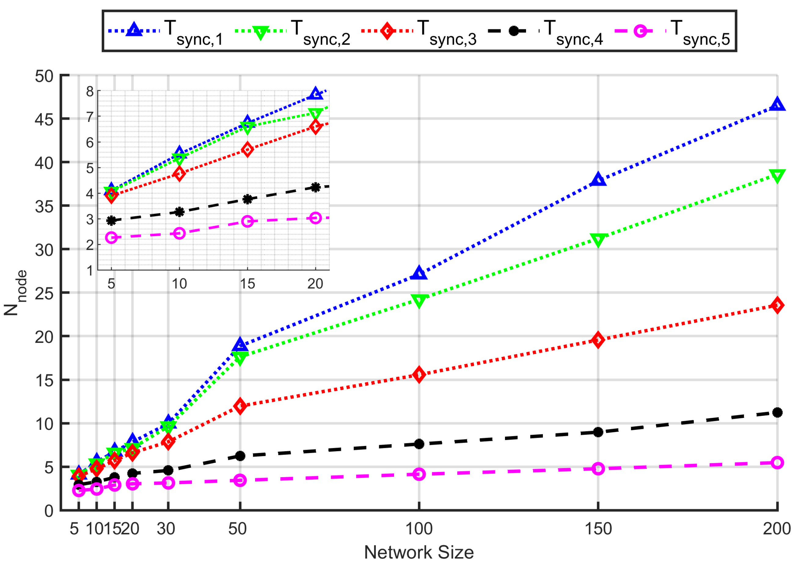
We used periodic beacon mechanism to synchronize the network. The UAV sends a beacon message to its surrounding coverage to announce its coming. The sensors that received the beacon send a join message which contains the location and the speed to the UAV. After the reception of the join messages from the sensor nodes, the data collection phase starts. The interval between adjacent beacons is named as synchronization intervals, and denoted as .
Figure 8 presents the scalability and the data collection performance of the network in different synchronization intervals and network size. It shows that the shorter the
, the larger the
. This is because the shorter
brings larger number of nodes that are detected. Thus, the number of nodes that participate the communication increased. It is also able to enhance the fairness of the network when appropriate
was selected. This is because the appropriate
brings the communication opportunity of those nodes that will never be detected in other case.
5.2. Extension of the U-WSN Use-Case to NTN-Aided IoT
The current state of the art shows the need for 3D modeling and simulation of NTN, including moving in space connected objects. Problems studied in the case of UWSN could be extended to general non-terrestrial network use cases. Opportunistic routing under energetic constraints is challenging, particularly in autonomous crewless vehicles and nano-satellites. Even though recent works on energy harvesting show the opportunity to optimize the overall system either through flying ad-hoc networks deployment [
84] and drones trajectory control [
85] or by using efficient data collection [
86] combined with fast wireless power transfer [
87]. The system control could be via centralized, distributed, or multi-tier architectures. Designed for WiFi devices, crowd-based schemes [
88] allow autonomous adaptive placement without exploiting the device’s location. The applicability of those distributed schemes raises energy optimization needs when it is a matter of things with low-power. The self-organization of the NTN is particularly challenging, to efficiently collect and send data via the network on intermittent connection to infrastructure to the cloud. Autonomy and placement to maintain permanent connectivity [
89] dictate revisiting communications from UAVs to the cloud, which are investigated in the context of 5G and beyond [
90].
Furthermore, in addition to the issues mentioned in this paper, there are wide open challenges in U-WSN applications. For example, the charging challenges, collision avoidance and swarming, etc.
The UAV missions necessitate effective energy management for battery-powered UAVs. Reliable, continuous, and intelligent management can help UAVs achieve their missions and prevent loss and damage. The UAV’s battery capacity is a crucial factor in enabling sustainable missions. However, as the battery capacity increases, its weight increases, which causes the UAV to consume more energy for a given task. The main directions in the literature to mitigate the limitations in UAV batteries are UAV battery management [
91], wireless charging for UAVs [
92], and solar powered UAVs [
93].
UAVs can collide with obstacles by moving or stationary objects in indoor or outdoor environments. Therefore, during UAV flights, it is vital to avoid accidents with these obstacles. Thus, the development of UAV collision avoidance techniques has gained research interest.
5.3. Future Edge Flying Servers
Edge computing is an optimization method that consists of processing data at the edge of the network, close to the data sources, i.e., near the sensors (at the border of the IoT perception layer). Basics of Mobile Edge computing are provided in [
94]. Drones with more computing capacity than sensors can thus play the role of Mobile Edge Servers. Therefore, it would be possible to minimize the bandwidth requirements between the sensors and the data processing centers by undertaking the analyses as close as possible to the On-ground data sources. There are several advantages to placing computation at the drone level. Indeed, this makes possible the placement of functions to reduce the volumes of data to be transmitted, perform complex tasks in particular for reconfigurable sensor architectures, correlate data from heterogeneous sources, etc. Furthermore, UAV-enabled Edge computing in IoT helps to avoid the transmission of irrelevant data to data centers or the cloud, thus bringing fluidity and speed of analysis and decision-making.
UAV-enabled edge server approaches require mobilizing resources that may not be permanently available. Consequently, the same networking challenges highlighted above are raised: the intermittency of the links, the Air-Ground contact duration, and the energy consumption, but also computing ones such as responsiveness and prioritization of task execution. Several issues can be considered in UAV-enabled edge computing for IoT, particularly those of data and task offloading.
6. Conclusions
In this article, we provided the main basics and features of UAV-enabled wireless sensor networks. Compared to traditional WSN, UAV-enabled WSNs present different issues and challenges. Through detailed analysis of the existing U-WSN applications, we refined the performance and the capability of the UAV and its functionalities when used as a communication node. In addition, the architectures, standard technologies, open issues, and challenges that emerge from this new paradigm are also mined. These insights may serve as motivations and guidelines for future designs of U-WSN.
The high flexibility of the UAV and the high dynamic topology of the network create new problems that cannot be ignored, the contact duration. In the future, the remaining contact duration between the UAV and the sensor would be a key criterion when addressing the issues in U-WSN, especially in the context where the sensor nodes are mobile. Because of the relative movement of the UAV and the sensors, the factors that influence the U-WSN design show difference from WSN. The UAV trajectory planning has become a link that cannot be crossed in the design of a U-WSN.
Author Contributions
Conceptualization, X.M., R.K. and R.D.; methodology, X.M., R.K. and R.D.; software, X.M.; validation, X.M., R.K. and R.D.; formal analysis, X.M., R.K., T.L., J.L. and R.D.; investigation, X.M., R.K., T.L., J.L. and R.D.; resources, X.M., R.K. and R.D.; data curation, X.M.; writing—original draft preparation, X.M., R.K. and R.D.; writing—review and editing, X.M., R.K., T.L., J.L. and R.D.; visualization, X.M., R.K. and R.D.; supervision, R.K. and R.D.; funding acquisition, R.D. All authors have read and agreed to the published version of the manuscript.
Funding
This research was funded by Shanghai Pujiang Talent Program (2020PJC107), and Zhejiang Province Qianjiang Talent Program (QJD2002010).
Institutional Review Board Statement
Not applicable.
Informed Consent Statement
Not applicable.
Data Availability Statement
Not applicable.
Acknowledgments
The authors would like to thank all reviewers and editors who helped improve the manuscript.
Conflicts of Interest
The authors declare no conflict of interest.
References
- Lee, S.H.; Lee, S.; Song, H.; Lee, H.S. Wireless sensor network design for tactical military applications: Remote large-scale environments. In Proceedings of the 2009 IEEE Conference on Military Communications, Piscataway, NJ, USA, 18–21 October 2009; pp. 911–917. [Google Scholar]
- De Almeida, D.R.A.; Broadbent, E.N.; Ferreira, M.P.; Meli, P.; Zambrano, A.M.A.; Gorgens, E.B.; Resende, A.F.; de Almeida, C.T.; Do Amaral, C.H.; Dalla Corte, A.P.; et al. Monitoring restored tropical forest diversity and structure through UAV-borne hyperspectral and lidar fusion. Remote Sens. Environ. 2021, 264, 112582. [Google Scholar] [CrossRef]
- Trotta, A.; Andreagiovanni, F.D.; Felice, M.D.; Natalizio, E.; Chowdhury, K.R. When uavs ride a bus: Towards energy-efficient city-scale video surveillance. In Proceedings of the 2018 IEEE Conference on Computer Communications (INFOCOM 2018), Honolulu, HI, USA, 16–19 April 2018; pp. 1043–1051. [Google Scholar]
- Ribeiro-Gomes, K.; Hernández-López, D.; Ortega, J.F.; Ballesteros, R.; Poblete, T.; Moreno, M.A. Uncooled thermal camera calibration and optimization of the photogrammetry process for uav applications in agriculture. Sensors 2017, 17, 2173. [Google Scholar] [CrossRef] [PubMed]
- López, A.; Jurado, J.M.; Ogayar, C.J.; Feito, F.R. A framework for registering UAV-based imagery for crop-tracking in Precision Agriculture. Int. J. Appl. Earth Obs. Geoinf. 2021, 97, 102274. [Google Scholar] [CrossRef]
- Zhao, M.; Ma, M.; Yang, Y. Efficient data gathering with mobile collectors and space-division multiple access technique in wireless sensor networks. IEEE Trans. Comput. 2014, 18, 400–417. [Google Scholar] [CrossRef]
- Ma, X.; Liu, T.; Liu, S.; Kacimi, R.; Dhaou, R. Priority-Based Data Collection for UAV-Aided Mobile Sensor Network. Sensors 2020, 20, 3034. [Google Scholar] [CrossRef]
- Gao, S.; Zhang, H.; Das, S.K. Efficient data collection in wireless sensor networks with path-constrained mobile sinks. IEEE Trans. Mob. Comput. 2011, 10, 592–608. [Google Scholar] [CrossRef]
- Huang, H.; Savkin, A.V.; Ding, M.; Huang, C. Mobile robots in wireless sensor networks: A survey on tasks. Comput. Netw. 2019, 148, 1–19. [Google Scholar] [CrossRef]
- Shakhatreh, H.; Sawalmeh, A.H.; Al-Fuqaha, A.; Dou, Z.; Almaita, E.; Khalil, I.; Othman, N.S.; Khreishah, A.; Guizani, M. Unmanned Aerial Vehicles (UAVs): A Survey on Civil Applications and Key Research Challenges. IEEE Access 2019, 7, 48572–48634. [Google Scholar] [CrossRef]
- Dalamagkidis, K. Classification of UAVs; Springer: Dordrecht, The Netherlands, 2015. [Google Scholar]
- Toth, J.; Gilpin-Jackson, A. Smart view for a smart grid—Unmanned aerial vehicles for transmission lines. In Proceedings of the 2010 1st International Conference on Applied Robotics for the Power Industry, Montreal, QC, Canada, 5–7 October 2010; pp. 1–6. [Google Scholar]
- Maza, I.; Caballero, F.; Capitán, J.; Martínez-de Dios, J.R.; Ollero, A. Experimental results in multi-uav coordination for disaster management and civil security applications. J. Intell. Robot. Syst. 2011, 61, 563–585. [Google Scholar] [CrossRef]
- Gómez, C.; Green, D.R. Small unmanned airborne systems to support oil and gas pipeline monitoring and mapping. Arab. J. Geosci. 2017, 10, 202. [Google Scholar] [CrossRef]
- Palmer, J.; Yuen, N.; Ore, J.P.; Detweiler, C.; Basha, E. On air-to-water radio communication between uavs and water sensor networks. In Proceedings of the 2015 IEEE International Conference on Robotics and Automation (ICRA), Seattle, WA, USA, 26–30 May 2015; pp. 5311–5317. [Google Scholar]
- Iacono, M.; Romano, E.; Marrone, S. Adaptive monitoring of marine disasters with intelligent mobile sensor networks. In Proceedings of the 2010 IEEE Workshop on Environmental Energy and Structural Monitoring Systems, Taranto, Italy, 9 September 2010; pp. 38–45. [Google Scholar]
- Ma, X.; Kacimi, R.; Dhaou, R. Fairness-aware uav-assisted data collection in mobile wireless sensor networks. In Proceedings of the 2016 International Wireless Communications and Mobile Computing Conference (IWCMC), Paphos, Cyprus, 5–9 September 2016; pp. 995–1001. [Google Scholar]
- Ma, X.; Chisiu, S.; Kacimi, R.; Dhaou, R. Opportunistic communications in wsn using uav. In Proceedings of the 2017 IEEE Consumer Communications and Networking Conference (CCNC 2017), Las Vegas, NV, USA, 8–11 January 2017; pp. 1–6. [Google Scholar]
- Ma, X.; Kacimi, R.; Dhaou, R. Adaptive hybrid mac protocols for uav-assisted mobile sensor networks. In Proceedings of the 2018 IEEE Annual Consumer Communications Networking Conference (CCNC 2018), Las Vegas, NV, USA, 12–15 January 2018; pp. 1–4. [Google Scholar]
- Basso, M.; Zacarias, I.; Leite, C.E.T.; Wang, H.; de Freitas, E.P. A practical deployment of a communication infrastructure to support the employment of multiple surveillance drones systems. Drones 2018, 2, 26. [Google Scholar] [CrossRef] [Green Version]
- Kashuba, S.V.; Novikov, V.I.; Lysenko, O.I.; Alekseeva, I.V. Optimization of uav path for wireless sensor network data gathering. In Proceedings of the 2015 IEEE International Conference Actual Problems of Unmanned Aerial Vehicles Developments (APUAVD), Kyiv, UKraine, 13–15 October 2015; pp. 280–283. [Google Scholar]
- Garraffa, M.; Bekhti, M.; Létocart, L.; Achir, N.; Boussetta, K. Drones path planning for wsn data gathering: A column generation heuristic approach. In Proceedings of the 2018 IEEE Wireless Communications and Networking Conference (WCNC), Barcelona, Spain, 15-18 April 2018; pp. 1–6. [Google Scholar]
- Wu, C.D.; Yang, J.Y.; Sun, Y.; Zhang, Y.Z. Study on uav path planning oriented to optimization of positioning error. Adv. Mater. Res. 2013, 791–793, 1357–1361. [Google Scholar] [CrossRef]
- Tazibt, C.Y.; Bekhti, M.; Djamah, T.; Achir, N.; Boussetta, K. Wireless sensor network clustering for uav-based data gathering. In Proceedings of the 2017 Wireless Days, Porto, Portugal, 29–31 March 2017; pp. 245–247. [Google Scholar]
- Pang, Y.; Zhang, Y.; Gu, Y.; Pan, M.; Han, Z.; Li, P. Efficient data collection for wireless rechargeable sensor clusters in Harsh terrains using UAVs. In Proceedings of the 2014 IEEE Global Communications Conference (GLOBECOM 2014), Austin, TX, USA, 8–12 December 2014; pp. 234–239. [Google Scholar]
- Sugihara, R.; Gupta, R.K. Optimal speed control of mobile node for data collection in sensor networks. IEEE Trans. Mob. Comput. 2010, 9, 127–139. [Google Scholar] [CrossRef]
- Bekhti, M.; Garraffa, M.; Achir, N.; Boussetta, K.; Létocart, L. Assessment of multi-uavs tracking for data gathering. In Proceedings of the 2017 International Wireless Communications and Mobile Computing Conference (IWCMC 2017), Valencia, Spain, 26–30 June 2017; pp. 1004–1009. [Google Scholar]
- Villas, L.A.; Guidoni, D.L.; Ueyama, J. 3D localization in wireless sensor networks using unmanned aerial vehicle. In Proceedings of the 2013 IEEE 12th International Symposium on Network Computing and Applications, Cambridge, MA, USA, 22–24 August 2013; pp. 135–142. [Google Scholar]
- Rullán-Lara, J.-L.; Salazar, S.; Lozano, R. Real-time localization of an uav using kalman filter and a wireless sensor network. J. Intell. Robot. Syst. 2012, 65, 283–293. [Google Scholar] [CrossRef]
- Miao, J.; Li, H.; Zheng, Z.; Wang, C. Secrecy Energy Efficiency Maximization for UAV Swarm Assisted Multi-Hop Relay System: Joint Trajectory Design and Power Control. IEEE Access 2021, 9, 37784–37799. [Google Scholar] [CrossRef]
- Ma, X.; Liu, T.; Kacimi, R.; Dhaou, R.; Liu, S. Duration-aware Data Collection in UAV-aided Mobile Sensor Networks. In Proceedings of the 2021 International Wireless Communications and Mobile Computing Conference (IWCMC), Harbin, China, 28 June–2 July 2021; pp. 394–399. [Google Scholar]
- Kacimi, R.; Dhaou, R.; Beylot, A.-L. Load balancing techniques for lifetime maximizing in wireless sensor networks. Ad Hoc Netw. 2013, 11, 2172–2186. [Google Scholar] [CrossRef] [Green Version]
- Bangali, J.; Shaligram, A. Energy efficient smart home based on wireless sensor network using labview. Am. J. Eng. Res. 2013, 2, 409–413. [Google Scholar]
- Djuknic, G.M.; Richton, R.E. Geolocation and assisted gps. Computer 2001, 34, 123–125. [Google Scholar] [CrossRef]
- Fang, S.H.; Lin, T. Principal component localization in indoor wlan environments. IEEE Trans. Mob. Comput. 2012, 11, 100–110. [Google Scholar] [CrossRef]
- Halder, S.; Ghosal, A. A survey on mobility-assisted localization techniques in wireless sensor networks. J. Netw. Comput. Appl. 2016, 60, 82–94. [Google Scholar] [CrossRef]
- IEEE 802.15.4. Available online: http://www.ieee802.org/15/ (accessed on 10 December 2021).
- Zigbee Alliance. Available online: http://www.zigbee.org (accessed on 10 December 2021).
- IEEE Stdandard 802.11-2016 (Revision of IEEE Std 802.11-2012); IEEE Standard for Information Technology–Telecommunications and Information Exchange between Systems—Local and Metropolitan Area Networks–Specific Requirements—Part 11: Wireless LAN Medium Access Control (MAC) and Physical Layer (PHY) Specifications. IEEE: Piscataway, NJ, USA, 2021; pp. 1–4379. [CrossRef]
- Rohde, S.; Putzke, M.; Wietfeld, C. Ad hoc self-healing of ofdma networks using uav-based relays. Ad Hoc Netw. 2013, 11, 1893–1906. [Google Scholar] [CrossRef]
- Bulusu, N.; Estrin, D.; Girod, L.; Heidemann, J. Scalable coordination for wireless sensor networks: Self-configuring localization systems. In Proceedings of the International Symposium on Communication Theory and Applications (ISCTA 2001), Ambleside, UK, July 2001. [Google Scholar]
- Shih, E.; Cho, S.; Ickes, N.; Min, R.; Sinha, A.; Wang, A.; Chandrakasan, A. Physical layer driven protocol and algorithm design for energy-efficient wireless sensor networks. In Proceedings of the ACM MobiCom’01, Rome, Italy, 16–21 July 2001; pp. 272–286. [Google Scholar]
- Petriu, E.M.; Georganas, N.D.; Petriu, D.C.; Makrakis, D.; Groza, V.Z. Sensor-based information appliances. IEEE Instrum. Meas. Mag. 2000, 3, 31–35. [Google Scholar]
- Cerpa, A.; Elson, J.; Hamilton, M.; Zhao, J. Habitat monitoring: Application driver for wireless communications technology. In Proceedings of the ACM SIGCOMM’2000, Stockholm, Sweden, 28 August–1 September 2000; pp. 20–41. [Google Scholar]
- Ma, X. Data Collection of Mobile Sensor Networks by Drones. Ph.D. Thesis, INPT, Rabat, Morocco, 2017. Available online: http://docplayer.fr/18339015-Theseen-vue-de-l-obtention-du-doctorat-de-l-universite-detoulouse.html (accessed on 6 November 2017).
- Hoblos, G.; Staroswiecki, M.; Aitouche, A. Optimal design of fault tolerant sensor networks. In Proceedings of the IEEE International Conference on Control Applications, Anchorage, AK, USA, 27 September 2000; pp. 467–472. [Google Scholar]
- Akyildiz, I.F.; Su, W.; Sankarasubramaniam, Y.; Cayirci, E. Wireless sensor networks: A survey. Comput. Netw. 2002, 38, 393–422. [Google Scholar] [CrossRef] [Green Version]
- Al-Hourani, A.; Kandeepan, S.; Hossain, E. Relay-assisted deviceto-device communication: A stochastic analysis of energy saving. IEEE Trans. Mob. Comput. 2016, 15, 3129–3141. [Google Scholar]
- Chen, K.; Chang, T.; Lee, T. Lifetime Maximization for Uplink Transmission in UAV-Enabled Wireless Networks. In Proceedings of the 2019 IEEE Wireless Communications and Networking Conference (WCNC), Marrakesh, Morocco, 15–18 April 2019; pp. 1–6. [Google Scholar]
- Rahmati, A.; Hosseinalipour, S.; Güvenç, İ.; Dai, H.; Bhuyan, A. Lifetime Maximization for UAV-assisted Data Gathering Networks in the Presence of Jamming. In Proceedings of the 2020 IEEE 21st International Workshop on Signal Processing Advances in Wireless Communications (SPAWC), Atlanta, GA, USA, 26–29 May 2020; pp. 1–5. [Google Scholar]
- Antunes, J.R.; Brisolara, L.; Ferreira, P.R. UAVs as Data Collectors in the WSNs: Investigating the Effects of Back-and-Forth and Spiral Coverage Paths in the Network Lifetime. In Proceedings of the 2020 X Brazilian Symposium on Computing Systems Engineering (SBESC), Florianopolis, Brazil, 24–27 November 2020; pp. 1–8. [Google Scholar]
- Chen, Y.; Wang, Z.; Cai, Z. Optimal Maintenance Decision Based on Remaining Useful Lifetime Prediction for the Equipment Subject to Imperfect Maintenance. IEEE Access 2020, 8, 6704–6716. [Google Scholar] [CrossRef]
- Yang, Z.; Xu, W.; Shikh-Bahaei, M. Energy Efficient UAV Communication With Energy Harvesting. IEEE Trans. Veh. Technol. 2020, 69, 1913–1927. [Google Scholar] [CrossRef] [Green Version]
- Ahmed, S.; Chowdhury, M.Z.; Jang, Y.M. Energy-Efficient UAV Relaying Communications to Serve Ground Nodes. IEEE Commun. Lett. 2020, 24, 849–852. [Google Scholar] [CrossRef]
- Qi, H.; Hu, Z.; Huang, H.; Wen, X.; Lu, Z. Energy Efficient 3-D UAV Control for Persistent Communication Service and Fairness: A Deep Reinforcement Learning Approach. IEEE Access 2020, 8, 53172–53184. [Google Scholar] [CrossRef]
- Zhang, X.; Duan, L. Energy-Saving Deployment Algorithms of UAV Swarm for Sustainable Wireless Coverage. IEEE Trans. Veh. Technol. 2020, 69, 10320–10335. [Google Scholar] [CrossRef]
- Yuan, X.; Yang, T.; Hu, Y.; Xu, J.; Schmeink, A. Trajectory Design for UAV-Enabled Multiuser Wireless Power Transfer With Nonlinear Energy Harvesting. IEEE Trans. Wirel. Commun. 2021, 20, 1105–1121. [Google Scholar] [CrossRef]
- Yang, G.; Dai, R.; Liang, Y.-C. Energy-Efficient UAV Backscatter Communication With Joint Trajectory Design and Resource Optimization. IEEE Trans. Wirel. Commun. 2021, 20, 926–941. [Google Scholar] [CrossRef]
- Kaminski, M.E. Drone federalism: Civilian drones and the things they carry. Calif. Law Rev. Circuit 2013, 57, 57–74. [Google Scholar]
- Gupta, L.; Jain, R.; Vaszkun, G. Survey of Important Issues in UAV Communication Networks. IEEE Commun. Surv. Tutor. 2016, 18, 1123–1152. [Google Scholar] [CrossRef] [Green Version]
- Su, W.; Akyildiz, I.F. Time-diffusion synchronization protocol for wireless sensor networks. IEEE/ACM Trans. Netw. 2005, 13, 384–397. [Google Scholar] [CrossRef]
- Li, Q.; Rus, D. Global clock synchronization in sensor networks. IEEE Trans. Comput. 2006, 55, 214–226. [Google Scholar]
- Zhang, B.; Sun, X.; Liu, S.; Lv, M.; Deng, X. Event-Triggered Adaptive Fault-Tolerant Synchronization Tracking Control for Multiple 6-DOF Fixed-Wing UAVs. IEEE Trans. Veh. Technol. 2021, 71, 148–161. [Google Scholar] [CrossRef]
- Yu, Z.; Zhang, Y.; Jiang, B.; Su, C.Y.; Fu, J.; Jin, Y.; Chai, T. Fractional-Order Adaptive Fault-Tolerant Synchronization Tracking Control of Networked Fixed-Wing UAVs Against Actuator-Sensor Faults via Intelligent Learning Mechanism. IEEE Trans. Neural Netw. Learn. Syst. 2021, 32, 5539–5553. [Google Scholar] [CrossRef] [PubMed]
- Li, H.; Chen, J.; Wang, F.; Bai, M. Ground-vehicle and unmanned-aerial-vehicle routing problems from two-echelon scheme perspective: A review. Eur. J. Oper. Res. 2021, 294, 1078–1095. [Google Scholar] [CrossRef]
- Hu, C.; Xia, Y.; Zhang, J. Adaptive operator quantum-behaved pigeon-inspired optimization algorithm with application to uav path planning. Algorithms 2018, 12, 3. [Google Scholar] [CrossRef] [Green Version]
- Chakraborty, S.; Goyal, N.K.; Soh, S. On Area Coverage Reliability of Mobile Wireless Sensor Networks With Multistate Nodes. IEEE Sens. J. 2020, 20, 4992–5003. [Google Scholar] [CrossRef]
- Dogru, S.; Marques, L. Energy efficient coverage path planning for autonomous mobile robots on 3d terrain. In Proceedings of the 2015 IEEE International Conference on Autonomous Robot Systems and Competitions, Vila Real, Portugal, 8–10 April 2015; pp. 118–123. [Google Scholar]
- Sheu, J.-P.; Sahoo, P.K.; Su, C.-H.; Hu, W.-K. Efficient path planning and data gathering protocols for the wireless sensor network. Comput. Commun. 2010, 33, 398–408. [Google Scholar] [CrossRef]
- Zhang, R.; Zhang, L.; Feng, Y. Very low energy consumption wireless sensor localization for danger environments with single mobile anchor node. Wirel. Pers. Commun. 2008, 47, 497–521. [Google Scholar] [CrossRef]
- Koutsonikolas, D.; Das, S.M.; Hu, Y.C. Path planning of mobile landmarks for localization in wireless sensor networks. Comput. Commun. 2007, 30, 2577–2592. [Google Scholar] [CrossRef]
- Huang, R.; Záruba, G.V. Static path planning for mobile beacons to localize sensor networks. In Proceedings of the IEEE International Conference on Pervasive Computing and Communications Workshops, White Plains, NY, USA, 19–23 March 2007; pp. 323–330. [Google Scholar]
- Hu, Z.; Gu, D.; Song, Z.; Li, H. Localization in wireless sensor networks using a mobile anchor node. In Proceedings of the 2008 IEEE/ASME International Conference on Advanced Intelligent Mechatronics, Xi’an, China, 2–5 July 2008; pp. 602–607. [Google Scholar]
- Guo, Z.; Guo, Y.; Hong, F.; Jin, Z.; He, Y.; Feng, Y.; Liu, Y. Perpendicular intersection: Locating wireless sensors with mobile beacon. IEEE Trans. Veh. Technol. 2010, 59, 3501–3509. [Google Scholar] [CrossRef]
- Han, G.; Xu, H.; Jiang, J.; Shu, L.; Hara, T.; Nishio, S. Path planning using a mobile anchor node based on trilateration in wireless sensor networks. Wirel. Commun. Mob. Comput. 2014, 13, 1324–1336. [Google Scholar] [CrossRef]
- Chen, H.; Huang, P.; Liang, J.; Gu, Y. Mobility-assisted node localization based on toa measurements without time synchronization in wireless sensor networks. Mob. Netw. Appl. 2012, 17, 90–99. [Google Scholar] [CrossRef]
- Cui, H.; Wang, Y. Four-mobile-beacon assisted localization in three-dimensional wireless sensor networks. Comput. Electr. Eng. 2012, 38, 652–661. [Google Scholar] [CrossRef]
- Kim, K.; Lee, W. MBAL: A mobile beacon-assisted localization scheme for wireless sensor networks. In Proceedings of the International Conference on Computer Communications and Networks, Honolulu, HI, USA, 13–16 August 2007; pp. 57–62. [Google Scholar]
- Li, H.; Wang, J.; Li, X.; Ma, H. Real-time path planning of mobile anchor node in localization for wireless sensor networks. In Proceedings of the International Conference on Information and Automation, Changsha, China, 20–23 June 2008; pp. 384–389. [Google Scholar]
- Fang, Z.; Luo, H.Y.; Lin, Q. A mobile beacon-assisted localization algorithm based on network-density clustering for wireless sensor networks. In Proceedings of the International Conference on Mobile Ad-Hoc and Sensor Networks, Fujian, China, 14–16 December 2009; pp. 304–310. [Google Scholar]
- Wang, H.; Qi, W.; Wang, K.; Liu, P.; Wei, L.; Zhu, Y. Mobile-assisted localization by stitching in wireless sensor networks. In Proceedings of the 2011 IEEE International Conference on Communications, Kyoto, Japan, 5–9 June 2011; pp. 1–5. [Google Scholar]
- Li, X.; Mitton, N.; Simplot-Ryl, I.; Simplot-Ryl, D. Dynamic beacon mobility scheduling for sensor localization. IEEE Trans. Parallel Distrib. Syst. 2012, 23, 1439–1452. [Google Scholar] [CrossRef]
- Ding, Y.; Wang, C.; Xiao, L. Using mobile beacons to locate sensors in obstructed environments. J. Parallel Distrib. Comput. 2010, 70, 644–656. [Google Scholar] [CrossRef]
- Silva, I.D.D.; Caillouet, C.; Coudert, D. Optimizing FANET deployment for mobile sensor tracking in disaster management scenario. In Proceedings of the 2021 International Conference on Information and Communication Technologies for Disaster Management (ICT-DM), Hangzhou, China, 3–5 December 2021; pp. 134–141. [Google Scholar]
- Silva, I.D.D.; Caillouet, C. Optimizing the trajectory of drones: Trade-off between distance and energy. In Proceedings of the 2020 IEEE International Conference on Sensing, Communication and Networking (SECON Workshops), Como, Italy, 22–26 June 2020; pp. 1–6. [Google Scholar]
- Caillouet, C.; Giroire, F.; Razafindralambo, T. Efficient data collection and tracking with flying drones. Ad Hoc Netw. 2019, 89, 35–46. [Google Scholar] [CrossRef] [Green Version]
- Caillouet, C.; Razafindralambo, T.; Zorbas, D. Optimal placement of drones for fast sensor energy replenishment using wireless power transfer. In Proceedings of the 2019 Wireless Days (WD), Manchester, UK, 24–26 April 2019; pp. 1–6. [Google Scholar]
- Rautu, D.; Dhaou, R.; Chaput, E. Crowd-based positioning of UAVs as access points. In Proceedings of the 2018 15th IEEE Annual Consumer Communications & Networking Conference (CCNC), Las Vegas, NV, USA, 12–15 January 2018; pp. 1–6. [Google Scholar]
- Rautu, D.; Dhaou, R.; Chaput, E. Maintaining a permanent connectivity between nodes of an air-to-ground communication network. In Proceedings of the 2017 13th International Wireless Communications and Mobile Computing Conference (IWCMC), Valencia, Spain, 26–30 June 2017; pp. 681–686. [Google Scholar]
- Li, B.; Fei, Z.; Zhang, Y. UAV Communications for 5G and Beyond: Recent Advances and Future Trends. IEEE Internet Things J. 2019, 6, 2241–2263. [Google Scholar] [CrossRef] [Green Version]
- Park, S.; Zhang, L.; Chakraborty, S. Battery assignment and scheduling for drone delivery businesses. In Proceedings of the ACM International Symposium on Low Power Electronics and Design (ISLPED), Taipei, Taiwan, 24–26 July 2017; pp. 1–6. [Google Scholar]
- Junaid, A.B.; Konoiko, A.; Zweiri, Y.; Sahinkaya, M.N.; Seneviratne, L. Autonomous wireless self-charging for multi-rotor unmanned aerial vehicles. Energies 2017, 10, 803. [Google Scholar] [CrossRef]
- Lee, J.-S.; Yu, K.-H. Optimal path planning of solar-powered UAV using gravitational potential energy. IEEE Trans. Aerosp. Electron. Syst. 2017, 53, 1442–1451. [Google Scholar] [CrossRef]
- Bréhon-Grataloup, L.; Kacimi, R.; Beylot, A.-L. Mobile edge computing for V2X architectures and applications: A survey. Comput. Netw. 2022, 206, 108797. [Google Scholar] [CrossRef]
| Publisher’s Note: MDPI stays neutral with regard to jurisdictional claims in published maps and institutional affiliations. |
© 2022 by the authors. Licensee MDPI, Basel, Switzerland. This article is an open access article distributed under the terms and conditions of the Creative Commons Attribution (CC BY) license (https://creativecommons.org/licenses/by/4.0/).


