Article

MUNILS: A Time-Synchronized and Traffic-Isolated Multi-UAV Simulation Platform Based on Integrated Physical and Network Simulators

1
Department of Applied Artificial Intelligence, Hansung University, Seoul 02876, Republic of Korea
2
Department of Computer Science and Artificial Intelligence, Dongguk University-Seoul, Seoul 04620, Republic of Korea
3
Department of Intelligent Network Convergence, Dongguk University-Seoul, Seoul 04620, Republic of Korea
*
Author to whom correspondence should be addressed.
†
These authors equally contributed to this work.
Drones 2026, 10(5), 387; https://doi.org/10.3390/drones10050387
Submission received: 9 April 2026 / Revised: 9 May 2026 / Accepted: 15 May 2026 / Published: 18 May 2026

Highlights

What are the main findings?
  • The study introduces the MUNILS platform, which seamlessly integrates the Gazebo physics engine, the PX4 flight controller, and the ns-3 network simulator via ROS2 middleware, achieving strict traffic isolation for each UAV using Linux network namespaces.
  • A precise cross-layer time synchronization mechanism was established across physical, control, and network domains, maintaining synchronization without cumulative clock drift during large-scale swarm operations on a single machine.
What are the implications of the main findings?
  • MUNILS enables researchers to accurately evaluate the bidirectional interactions between network conditions and physical flight behaviors in real time, providing a highly reliable verification environment for complex multi-UAV operations.
  • By facilitating scalable and synchronized co-simulation, the platform significantly mitigates the substantial costs, safety hazards, and lack of repeatability inherent in real-world physical testing.

Abstract

Recent advancements in Unmanned Aerial Vehicle (UAV) physics simulators, flight control firmware, and network virtualization have been substantial. However, operating these systems independently fails to capture the complex dynamics of real-world multi-UAV networks, thereby compromising simulation reliability. To address this, we propose the Multi-UAV Network-in-the-Loop Simulation (MUNILS) platform, which seamlessly integrates the Gazebo physics engine, the PX4 flight controller, and the ns-3 network simulator via Robot Operating System 2 (ROS2) middleware. Specifically, MUNILS leverages Micro eXtremely Resource Constrained Environments–Data Distribution Service (XRCE-DDS) for high-speed data bridging and employs Linux network namespaces to enforce traffic isolation and routing exclusively through ns-3. Crucially, we introduce a precise cross-layer time synchronization mechanism spanning the physical, control, and network domains to resolve inherent clock discrepancies among these heterogeneous simulators. Experimental evaluations confirm that MUNILS achieves strict traffic isolation, scalable closed-loop flight control, and highly accurate time synchronization across all integrated modules (Gazebo, ns-3, ROS2, and PX4) without cumulative clock drift, thereby providing a highly reliable verification environment for large-scale swarm operations on a single machine.

1. Introduction

Recent advancements in Unmanned Aerial Vehicle (UAV) technology have spurred active research into complex, multi-UAV missions, such as swarm flight and cooperative exploration in disaster zones [1,2]. The successful operation of these multi-UAV systems depends not only on the efficacy of individual flight control algorithms but also on reliable communication networks among the UAVs and with ground control stations [3,4]. However, verifying the operational performance of such systems in real-world testbeds entails substantial costs and carries significant risks of equipment damage and safety hazards [5]. Furthermore, real-world environments inherently lack repeatability; uncontrolled variables, such as wind gusts and radio frequency (RF) interference, make it nearly impossible to conduct experiments under identical physical and communication conditions. Consequently, it is imperative to establish a high-fidelity simulation environment capable of simultaneously modeling physical behaviors and network conditions prior to actual deployment [6].
In response to these demands, the advent of the Robot Operating System 2 (ROS2) [7] has provided a robust middleware framework that supports real-time execution and distributed architectures. Moreover, the introduction of efficient bridging protocols, such as Micro eXtremely Resource Constrained Environments–Data Distribution Service (XRCE-DDS) [8], has facilitated high-speed data exchange between resource-constrained embedded firmware (e.g., PX4 [9]) and high-performance ROS2 environments, laying the groundwork for the seamless integration of heterogeneous systems. Driven by these technological milestones, the development of UAV simulators has accelerated significantly.
Nevertheless, existing UAV simulation methodologies have largely bifurcated into two distinct domains. Physics simulators, such as Gazebo [10], typically assume an ideal communication environment devoid of latency or packet loss. Conversely, network simulators like ns-3 [11] lack real-time coupling with the physical dynamics and flight control logic of the UAVs. This decoupled approach makes it exceedingly difficult to quantitatively evaluate the network-physical interaction. This interaction is a bidirectional phenomenon where network degradation (e.g., packet loss or delay) impairs flight stability, while conversely, changes in the physical environment disrupt communication performance.
To overcome these limitations, we propose MUNILS, a Multi-UAV Network-in-the-Loop Simulation platform. Rather than developing new physics or wireless channel simulators, MUNILS focuses on the organic integration of well-established and independently validated simulators, such as Gazebo for physical dynamics, PX4 for flight control, and ns-3 for network emulation, into a unified co-simulation framework via ROS2 middleware. Utilizing ROS2 as the communication backbone, MUNILS establishes a closed-loop architecture where all data exchanges between the PX4 firmware and the offboard controller are entirely routed through an ns-3-emulated virtual network. This design ensures that the impacts of network latency and packet loss are directly reflected in the UAVs’ physical behaviors in real time. Furthermore, MUNILS is built as a single-machine co-simulation environment with flexible scalability in the number of concurrently simulated UAV instances, allowing this number to be easily reconfigured and adapted across a wide range of swarm scales without modifying the underlying integration.
The main contributions of this study are threefold:
1.
Implementation of a highly isolated Network-in-the-Loop platform: We developed MUNILS to guarantee strict traffic isolation between simulated nodes using Linux kernel-level Network Namespaces (NNS). Going beyond simple port mapping, this approach enforces host-level traffic isolation for each UAV, routing all packets exclusively through ns-3. This practically eliminates unintended signal interference, even in dense multi-UAV scenarios.
2.
Cross-layer time synchronization and real-time verification: We established a unified timeline to synchronize physical behavioral data with network communication states across heterogeneous simulators. This synchronized environment allows for the real-time monitoring of how transient communication drops instantly affect physical flight reactions.
3.
Automated orchestration and operational flexibility: We ensured high operational efficiency by employing automated orchestration scripts, allowing multiple UAV instances to be seamlessly instantiated on a single machine. Furthermore, by leveraging ROS2’s Node Remapping features, we present a highly scalable architecture capable of individually identifying and flexibly controlling multiple heterogeneous UAVs using a unified control algorithm.
The remainder of this paper is organized as follows. Section 2 reviews related work on UAV simulations. Section 3 details the proposed MUNILS architecture. Section 4 describes the implementation of the platform and presents the experimental validation results. Finally, Section 5 concludes the paper.

2. Related Work

This section reviews existing physics-centric and network-centric UAV simulation platforms. We then examine the limitations of prior co-simulation frameworks and detail how the proposed MUNILS platform resolves these challenges through improved traffic isolation and time synchronization.

2.1. Classification of UAV Simulation Platforms

Existing research on UAV simulators generally falls into two distinct categories based on the primary focus of the simulation: physics-centric and network-centric approaches.
Physics-centric simulators prioritize the precision of UAV physical dynamics and sensor modeling. For instance, Kim et al. [12] implemented a physics-based UAV simulation using Gazebo by incorporating depth camera noise and air drag force models. Ma et al. [13] constructed an environment for verifying autonomous flight algorithms by integrating AirSim [14] with ROS. Although these platforms exhibit excellent interoperability with ROS, they struggle to accurately reflect the impact of communication quality degradation on physical behavior. These systems typically assume an ideal network environment devoid of latency and packet loss, or they utilize heavily simplified communication models.
Conversely, network-centric simulators specialize in the precise replication of wireless communication protocol stacks. Su et al. [15] proposed a modular simulator for connected UAV communication in 5G networks, and Keller et al. [16] analyzed the performance of WiFi mesh networks among mobile nodes using ns-3. However, coupling these network models in real time with actual flight dynamics or embedded flight control logic, such as PX4, remains a significant technical challenge. Consequently, verifying the comprehensive interactions between network conditions and physical flight systems using isolated simulators is highly constrained.

2.2. Co-Simulation Approaches and Inherent Challenges

To address the dichotomy between physical and network accuracy, researchers have explored co-simulation frameworks that link physical engines with network simulators. However, existing efforts exhibit specific structural limitations when applied to large-scale multi-UAV scenarios that demand strict isolation, modern flight control integration, and rigorous synchronization simultaneously. The ns3_gazebo package from nps-ros2 [17] presents one of the earliest attempts at directly integrating ROS2, Gazebo, and ns-3, yet exhibits two structural shortcomings. First, it does not enforce host-level traffic isolation: because simulated nodes share the host’s loopback interface, control packets can bypass the emulated network entirely, and the simulated delay or loss is therefore not faithfully reflected in flight behavior. Second, the framework provides only a generic ROS2-Gazebo-ns-3 coupling without native integration with modern flight control firmware such as PX4 via the Micro XRCE-DDS bridge, limiting its applicability to UAV-specific co-simulation scenarios that require closed-loop interaction with embedded flight control logic. Other middleware-based co-simulation approaches present complementary, but equally restrictive, limitations. CORNET, proposed by Acharya et al. [18], introduces a middleware layer for robot networks but depends on the no-longer-supported ROS1 [19] framework and, consequently, does not interoperate with the modern PX4-ROS2-Micro XRCE-DDS flight control pipeline; integration with current firmware would require non-trivial reimplementation of the middleware layer. In addition, the framework lacks a built-in mechanism for orchestrating large numbers of concurrent UAV instances on a single machine. The architecture introduced by Ponniah et al. [20] is similarly tailored to a specific protocol-development context rather than to a general-purpose, scalable multi-UAV co-simulation environment and does not explicitly address kernel-level traffic isolation or cross-layer time synchronization.
Crucially, the primary obstacle in co-simulation is the time synchronization discrepancy between systems operating on different clock mechanisms. As highlighted by Park et al. [21] and Moon et al. [22], mismatches between the event-driven clock of a network simulator and the time-driven clock of a physics engine distort the observed impact of network delays on flight control. This discrepancy severely degrades overall simulation fidelity. Therefore, a global time synchronization mechanism spanning the physical, control, and network layers is an absolute prerequisite for accurate closed-loop simulation.
Collectively, these prior frameworks fail to simultaneously satisfy the four core requirements essential for high-performance multi-UAV co-simulation: kernel-level traffic isolation among concurrently running UAV instances, integration with the modern PX4-ROS2-Micro XRCE-DDS flight control stack, precise time synchronization spanning the physical, control, and network layers, and scalable orchestration of large UAV swarms on a single machine. This gap motivates the design of MUNILS.

2.3. Differentiation of the Proposed Platform

While existing studies often necessitate a trade-off between physical accuracy and network realism or fail to resolve synchronization and isolation limitations, the MUNILS platform proposed in this study addresses these gaps across three critical dimensions.
First, MUNILS ensures rigorous traffic isolation. Previous multi-UAV co-simulation frameworks [17] primarily relied on port mapping or basic IP assignment methods. Since these methods share the host system’s loopback interface, preventing traffic leakage remains fundamentally difficult. Packets often route directly within the host rather than traversing the simulated network, meaning simulated delays or packet losses fail to affect the actual control communication. In contrast, MUNILS leverages Linux kernel-level Network Namespaces to physically isolate the internal control traffic from external cooperative traffic at the host level. This architecture guarantees that all external communication is strictly routed through ns-3.
Second, the platform implements precise time synchronization across heterogeneous simulators. Simple integrations of event-driven and time-driven simulators suffer from clock drift, leading to a loss of data consistency over time [21,22]. Notably, previous studies frequently neglected these errors or relied on post-simulation corrections. Conversely, MUNILS introduces a global synchronization architecture governed by the ROS2 /clock topic. By disabling the internal clock of the PX4 firmware and subordinating it to the middleware timeline, the platform achieves strict temporal integrity. A network delay of one millisecond in ns-3 translates exactly to a one-millisecond delay in the physical control loop.
Third, MUNILS provides superior scalability and operational efficiency based on a modernized architecture. Unlike older middleware solutions [18] restricted to legacy firmware, MUNILS fully adopts the Micro XRCE-DDS bridging protocol alongside the latest ROS2 Humble and PX4 architectures. Furthermore, to mitigate the complex manual configurations previously required for multi-UAV setups, this study incorporates automated orchestration and ROS2 Node Remapping technologies. This approach yields a highly flexible environment, enabling the immediate deployment and control of multiple heterogeneous UAVs from a single machine without necessitating underlying code modifications.
Table 1 consolidates this comparison across all relevant architectural dimensions. As shown in the table, while prior frameworks each address a subset of these requirements, MUNILS is the only platform that simultaneously supports modern ROS2-PX4 integration, kernel-level traffic isolation, cross-layer time synchronization, and automated orchestration on a single machine, thereby filling the gap left by existing co-simulation approaches.

3. System Design

MUNILS presents a co-simulation architecture designed to execute realistic multi-UAV networking scenarios. We define a closed-loop interaction scheme between the physics engine and the network simulator. This design is predicated on the principle that the dynamic mobility of UAVs alters network performance, while network latency concurrently affects flight stability. To realize this bidirectional interaction accurately, we propose a highly reliable co-simulation framework integrating ROS2, Gazebo, and ns-3, which satisfies strict traffic isolation and time synchronization requirements. Section 3.1 provides an overview of the proposed platform’s architecture. Subsequently, Section 3.2 details the network isolation mechanism, and Section 3.3 addresses the global time synchronization architecture.

3.1. System Overview

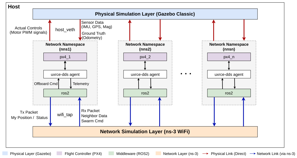
Figure 1 illustrates the overall architecture of MUNILS. The platform features a closed-loop structure integrating the physical layer (Gazebo), the flight control layer (PX4), and the network layer (ns-3) through ROS2 middleware. Specifically, the key components are organically connected as follows:
  • Integrated Framework (ROS2 Humble) acts as the backbone that integrates distributed components and manages data communication.
  • Flight Controller (PX4 Autopilot) executes attitude control and navigation logic for the virtual UAV model within Gazebo.
  • Virtual Test Environment (Gazebo Classic) simulates the physical environment of the UAV and ensures simulation stability based on Gazebo 11, which possesses verified compatibility with PX4 Software-In-The-Loop (SITL).
  • Network Simulation (ns-3) precisely models the wireless communication environment among multiple UAVs at the packet level.
  • Communication Bridge (Micro XRCE-DDS Agent) mediates User Datagram Protocol (UDP)-based communication between the embedded environment (PX4) and the ROS2 system.
Beyond the individual roles of these components, the core hallmark of the MUNILS architecture is its ability to capture the complex, bidirectional interactions between flight dynamics and wireless networking. By bridging the embedded PX4 environment and the high-level ROS2 system via the Micro XRCE-DDS Agent, the platform ensures that the flight controller can interact with the Gazebo simulation environment without sacrificing temporal integrity. Separating component responsibilities from communication interfaces allows the physical, control, and network layers to be independently scaled or replaced. This architecture provides the flexibility required for large-scale multi-UAV scenarios.
To achieve strict simulation integrity and scalability, MUNILS employs a hierarchical isolation and routing mechanism centered on Linux network namespaces. As shown in the dotted boxes of Figure 1, each UAV is encapsulated within its own namespace, packaging the PX4 instance, the Micro XRCE-DDS Agent, and the offboard ROS2 node into a single isolated execution unit. Within this namespace, internal traffic, including sensor data acquisition and attitude control commands, is processed via a local loopback interface to accurately replicate the hardwired connection of an actual onboard mission computer. Conversely, external traffic is bifurcated into two distinct paths: high-bandwidth physical data (IMU, GPS, and ground-truth odometry) is routed through the host_veth interface to communicate directly with Gazebo, while all inter-UAV cooperative data is mandatorily funneled through the wifi_tap interface to ns-3. This dual-path architecture ensures that the real-time stability of the flight control loop is preserved, while swarm-level interactions are strictly subjected to realistic network-induced latency and packet loss.
This dual-routing architecture establishes a comprehensive experimental environment. It guarantees the real-time execution of the internal control loop, which is directly related to physical flight stability, while simultaneously enabling the precise verification of multi-UAV cooperative performance under varying network conditions.

3.2. Network Isolation and Traffic Routing

To prevent the mutual interference of heterogeneous data traffic in a multi-UAV environment and to ensure simulation integrity, we applied Linux kernel-based network isolation technology. Unlike existing studies that rely on simple port mapping, the proposed architecture implements a complete isolation structure utilizing network namespaces alongside a selective routing mechanism based on virtual interfaces.
During the simulation initialization phase, independent network namespaces (nns1 to nnsN) corresponding to the user-specified number of UAVs (N) are generated via a custom network configuration script. Inside each namespace, two distinct types of virtual Ethernet (veth) interfaces are assigned to establish the dual-path architecture visualized in Figure 1: the Physical Link (indicated by red arrows) and the Network Link (indicated by blue arrows). The host_veth interface, corresponding to the Physical Link, is directly connected to the host system (Gazebo) via the 10.100.x.x subnet. This interface serves as a high-speed link to exchange large-capacity physical sensor data and render information without artificial delay. In contrast, the wifi_tap interface, corresponding to the Network Link, connects directly to the ns-3 simulator. This path handles the actual inter-UAV communication packets and is configured to interoperate with the wireless channel model of ns-3 through a dedicated bridge (wifi_br).
Process execution within these isolated spaces is automated by an orchestration script. This script utilizes the ip netns exec command to launch the PX4 instance, the Micro XRCE-DDS Agent, and the ROS2 nodes inside their designated namespace. Furthermore, it dynamically injects essential environment variables to control the traffic flow of each specific instance. By setting the PX4_SIM_HOSTNAME environment variable to the IP address of the host_veth interface (e.g., 10.100.1.1), physical simulation traffic is forced to bypass ns-3 and communicate directly with the host engine. This configuration mitigates severe computational bottlenecks caused by network simulation overhead, thereby preserving the temporal integrity of the physics engine even in large-scale scenarios. Additionally, the PX4_UXRCE_DDS_HOST variable is set to 127.0.0.1 (localhost), ensuring that the internal communication between PX4 and ROS2 is processed immediately within the namespace via the loopback interface. As discussed in Section 3.1, this precisely replicates the wired onboard environment.
Consequently, this explicit separation of traffic paths yields a highly reliable experimental environment. High-bandwidth sensor data is stably processed through the isolated Physical Link, preserving the real-time stability of the flight controller. Simultaneously, outbound Micro Air Vehicle Link (MAVLink) [23] messages and swarm control packets are strictly routed through the Network Link via the wifi_tap interface, compelling the traffic to undergo the rigorous simulation logic of ns-3. This architecture successfully achieves both physical independence and network realism, utilizing Linux kernel functionalities within a single machine.

3.3. Time Synchronization

When integrating heterogeneous simulators operating on fundamentally different time bases, clock source discrepancy is a critical factor that severely degrades co-simulation fidelity. ns-3 is a discrete-event simulator (DES) that advances time by dequeuing timestamped events and has no intrinsic relation to wall-clock time unless explicitly constrained. Gazebo, by contrast, is a time-stepped physics engine that advances its internal clock at a configurable real-time factor (RTF) and publishes the authoritative simulation time on the ROS2 /clock topic at each physics step. PX4 maintains its own microsecond-resolution monotonic clock, which it normally self-synchronizes via the XRCE-DDS bridge. Left unconstrained, these three independent time sources diverge progressively, causing a one-millisecond delay introduced in ns-3 to no longer correspond to a one-millisecond delay perceived by the flight controller. This result is a fundamental loss of co-simulation integrity. To resolve this, MUNILS implements a hierarchical synchronization architecture with Gazebo as the single authoritative time source.
Gazebo is chosen as the master because both the physics engine and the PX4 control loop are fixed-step, time-driven systems whose correctness depends on consistent wall-clock-paced progression. In contrast, ns-3 operates on logical time and can be subordinated to an external clock without violating its event-scheduling semantics. We further adopt unilateral subordination rather than a federate-style bidirectional protocol [24], since none of the three simulators expose a native federate interface, and barrier-based lockstep would throttle the entire pipeline to the slowest component. A further benefit of this master-slave structure is that transient Operating System scheduling backlogs on a single machine are absorbed as time-scale adjustments at the master clock, as reflected in Gazebo’s RTF, and uniformly propagated to ROS2, PX4, and ns-3 via the /clock topic. This eliminates the need for explicit handshakes or per-module compensation logic. The hierarchy is therefore realized in three levels, applied bottom-up across PX4, ROS2, and ns-3.

3.3.1. Level 1: PX4 Clock Subordination

In the PX4 initialization script, the parameter UXRCE_DDS_SYNCT is explicitly set to false. This disables PX4’s independent internal clock-synchronization routine, causing the firmware to derive its time reference entirely from the ROS2 /clock topic forwarded by the Micro XRCE-DDS bridge. Consequently, every PX4 timestamp, including those for IMU samples, GPS fixes, and control-loop ticks, is expressed in the same simulation time domain as Gazebo. The practical effect is that a simulated communication delay of d milliseconds in ns-3 produces an identical d-millisecond delay in the physical control loop, preserving the causal relationship between network events and flight responses.

3.3.2. Level 2: ROS2 Sim-Time Enforcement

All ROS2 nodes (offboard controllers, telemetry relays, and the measurement probe) are launched with the use_sim_time:=true parameter, instructing the ROS2 time Application Programming Interface (API) to source all now() calls from the /clock topic rather than the system wall clock. The /clock topic is produced by Gazebo via the clock_bridge function of the ros_gz_bridge package, which converts gz.msgs.Clock to the ROS2 rosgraph_msgs/Clock format so that the entire ROS2 layer operates on a unified, Gazebo-synchronized timeline.

3.3.3. Level 3: ns-3 Soft Synchronization via Shared Memory

Unlike PX4 and ROS2, ns-3 has no native hook to subscribe to an external clock, since its RealtimeSimulatorImpl paces event execution directly against the host wall clock and can advance faster than Gazebo whenever the RTF drops below 1.0. If the divergence between the slowed Gazebo simulation and ns-3 persists, the resulting drift can accumulate and break the correspondence between simulated network delays and the physical timeline. To address this, we implement a conservative bounded synchronization mechanism within the ns-3 RealtimeSimulatorImpl::ProcessOneEvent() loop, coupled with a lock-free shared-memory channel that propagates the Gazebo simulation time to ns-3 with negligible overhead.
A dedicated ROS2 relay node subscribes to /clock with BEST_EFFORT QoS and writes the Gazebo simulation time, encoded as a 64-bit unsigned integer in nanoseconds, to a POSIX shared-memory segment (/gazebo_shared_simtime, 8 bytes, mmap-based) at the Gazebo physics-step rate of 1 kHz. On the ns-3 side, a lightweight reader opens the same segment at initialization and exposes a single accessor that performs an aligned 64-bit read. Because the write size matches the processor’s native word size and ns-3 tolerates at most one stale value between consecutive Gazebo steps, the read operation is lock-free and adds negligible overhead per event-loop iteration.

3.3.4. Synchronization Rule

Let t ns 3 ∈ R ≥ 0 denote the wall-clock reference (in seconds) observed by ns-3 at the current event-loop iteration, and  let t gz ( t ns 3 ) denote the Gazebo simulation time corresponding to the same wall-clock instant, read from the shared-memory segment. The pair ( t ns 3 , 0 , t gz , 0 ) is defined as the values of t ns 3 and t gz ( t ns 3 ) latched on the first iteration where t gz ( t ns 3 ) > 0 , i.e., when Gazebo has published at least one /clock message. This pair serves as the joint calibration origin and remains constant thereafter. The drift between the two timelines is defined as
Δ t ns 3 , gz ( t ns 3 ) = t ns 3 − t ns 3 , 0 − t gz ( t ns 3 ) − t gz , 0 ,
and the bounded synchronization rule is applied as
t ns 3 ← t ns 3 , 0 + t gz ( t ns 3 ) − t gz , 0 if Δ t ns 3 , gz ( t ns 3 ) > δ , t ns 3 otherwise ,
The rule is intentionally one-sided: when Δ t ns 3 , gz ( t ns 3 ) ≤ δ , which encompasses both ns-3 lagging Gazebo ( Δ t ns 3 , gz < 0 ) and small bounded leads ( 0 ≤ Δ t ns 3 , gz ≤ δ ), no correction is applied, since artificially advancing event execution would violate causality. The  t ns 3 value, which is potentially clamped, is then used to compute the scheduler sleep duration
t delay = max 0 , t next − t ns 3 ,
where t next is the timestamp of the next scheduled ns-3 event. This sleep duration is passed to the WallClockSynchronizer, which applies it via a sleep-spin mechanism, rate-limiting ns-3 to follow Gazebo without blocking the physics process.

3.3.5. Granularity and Packet-Level Fidelity

The master-clock granularity does not distort packet-level modeling: Gazebo runs at a 1 kHz physics step (1 ms per tick) [25] while ns-3 retains its native nanosecond event resolution [11], and  t gz ( t ns 3 ) is sampled by ns-3 on every ProcessOneEvent() call rather than once per tick. Consequently, packet events are neither aggregated into Gazebo ticks nor quantized to the 1 ms grid. The threshold δ = 20  ms was deliberately chosen to be substantially larger than one tick yet small relative to typical end-to-end network delays in UAV scenarios (tens to hundreds of milliseconds) [26] and the inter-event interval of the ns-3 IEEE 802.11a model (approximately 1–5 ms for packet transmissions) [27], so that the clamp activates only against genuine wall-clock drift rather than against the inherent jitter of a fixed-step physics engine.

4. Implementation and Experimental Validation

This section details the implementation of the MUNILS platform and presents its comprehensive experimental validation. First, we outline the system implementation, including the environment setup and automation mechanisms. Subsequently, we demonstrate the platform’s robust scalability and capabilities through large-scale multi-UAV swarm flight scenarios, focusing on network traffic isolation, flight control stability, and precise cross-layer time synchronization among the heterogeneous modules (Gazebo, ns-3, ROS2, and PX4).

4.1. Implementation Details

This subsection outlines the technical procedures required to construct the MUNILS platform. We first detail the hardware and software environment configurations, specifically addressing compatibility resolutions among heterogeneous simulators. Subsequently, we explain the automated orchestration mechanisms developed to efficiently deploy and manage multiple UAV instances.

4.1.1. Environment Setup and Legacy Compatibility

MUNILS was implemented in the following environment. The hardware specifications include an AMD Ryzen 7 6800H processor (8-core, 16-thread, 3.2 GHz), 32 GB DDR5 memory, and an NVIDIA GeForce RTX 3070 Graphics Processing Unit (GPU) with 8 GB GDDR6 memory. The software environment is built on the Ubuntu 22.04 Long-Term Support (LTS) operating system, utilizing ROS2 Humble as the core middleware. The primary simulation components comprise Gazebo Classic 11.10.2 for physical dynamics, PX4 Autopilot v1.14 for flight control logic, and ns-3 v3.29 for network emulation.
Integrating these heterogeneous simulators required resolving several version dependency conflicts. We addressed these challenges through specific engineering approaches. First, to ensure full compatibility with the PX4 SITL architecture, which is optimized for stability-verified environments, we enforced the installation of Gazebo Classic 11 rather than adopting the operating system’s default newer Gazebo iterations. Second, to facilitate the wireless network simulation using ns-3.29, we modified the Waf build script. This modification resolved syntax errors originating from the modern Python 3 environment, thereby ensuring the stable generation of the required execution binaries.

4.1.2. Multi-UAV Orchestration and Automation

To reduce the operational complexity of coordinating heterogeneous simulators and to support scalable multi-UAV experiments, we implemented an orchestration mechanism that automates the entire deployment pipeline. Specifically, a custom shell script instantiates a user-specified number of PX4 instances (N) from a single command, assigns deterministic MAVLink Transmission Control Protocol (TCP)/UDP ports and system identifiers to each instance, and generates the corresponding Simulation Description Format (SDF) model files. Although the Micro XRCE-DDS communication port is standardized across all instances, resource conflicts are avoided by isolating each PX4 process within a dedicated network namespace. This design enables reproducible and conflict-free initialization of concurrent UAV instances. The overall deployment workflow is summarized in Algorithm 1.
As shown in Algorithm 1, the script first terminates any residual processes from prior sessions to ensure a clean execution state. It then initializes the Gazebo simulation environment and sequentially deploys each UAV instance. For each instance i, the MAVLink TCP port ( 4560 + i ), UDP port ( 14560 + i ), and system identifier ( 1 + i ) are deterministically assigned to guarantee that no two instances share the same communication endpoint. The generated SDF model file embeds these parameters, after which the corresponding UAV is spawned in Gazebo at a pre-defined position.
Algorithm 1 Automated Multi-UAV Instance Deployment
Require: Number of UAVs N, vehicle model M , simulation world W
Ensure: N UAV instances initialized with deterministic communication settings and isolated execution contexts
  1:
Terminate previously running PX4 and Gazebo processes
  2:
Load the simulation environment for Gazebo and PX4
  3:
Launch the Gazebo server with world W
  4:
for  i = 1  to N do
  5:
     p tcp ← 4560 + i                      ▹ MAVLink TCP port
  6:
     p udp ← 14560 + i                     ▹ MAVLink UDP port
  7:
     id mav ← 1 + i                          ▹ MAVLink system ID
  8:
    Generate the SDF model file for M i
  9:
    Spawn M i in Gazebo at the designated initial position ( x i , y i )
10:
    LaunchInstance(i)
11:
end for
For each spawned instance, the script subsequently prepares a dedicated execution context within the corresponding network namespace and launches the PX4 SITL process with the appropriate per-instance environment variables, as outlined in Algorithm 2. This two-phase design separates the physical model deployment from the per-UAV software stack initialization, thereby simplifying debugging and allowing operators to verify the Gazebo environment before the flight control processes begin.
Algorithm 2 Per-UAV Namespace Configuration and Process Launch
Require: UAV index i
Ensure: PX4 instance i launched in an isolated namespace with synchronized DDS and ROS2 interfaces
1:
Create the per-instance working directory for UAV i
2:
Configure environment variables:
3:
    PX 4 _ SIM _ HOSTNAME ← 10 . 100 . i . 1
4:
    PX 4 _ UXRCE _ DDS _ HOST ← 127 . 0 . 0 . 1
5:
    PX 4 _ UXRCE _ DDS _ PORT ← 8888
6:
    UXRCE _ DDS _ SYNCT ← false         ▹Subordinate to the external ROS2 /clock in Section 3.3
7:
Launch PX4 SITL instance i inside nnsi using ip netns exec
8:
Start the corresponding DDS agent and ROS2 offboard node associated with UAV i
9:
Apply runtime namespace remapping to separate per-UAV topics and control channels
In Algorithm 2, three environment variables govern the traffic routing behavior of each PX4 instance. The PX4_SIM_HOSTNAME variable directs physics simulation traffic to the host-side host_veth interface, establishing the Physical Link described in Section 3.2. The PX4_UXRCE_DDS_HOST variable binds the DDS bridge to the loopback address, confining internal control traffic within the namespace. In addition, the UXRCE_DDS_SYNCT flag is explicitly disabled so that the PX4 internal clock follows the global ROS2 /clock timeline, as detailed in Section 3.3.
The DDS bridge processes are managed separately by a companion agent orchestration script, as summarized in Algorithm 3. This script launches one Micro XRCE-DDS agent inside each isolated namespace using the fixed communication port, redirects the standard output and error streams to per-instance log files, records the corresponding process identifiers, and provides a cleanup routine for controlled shutdown. Through this design, the high-level control layer is connected to the simulated flight stack in a reproducible and scalable manner.
Algorithm 3 Companion Micro XRCE-DDS Agent Orchestration
Require: Number of UAVs N, fixed DDS communication port p dds = 8888
Ensure: One Micro XRCE-DDS agent launched in the background for each namespace, with logs and process IDs recorded
  1:
Initialize the log directory and remove any existing PID file
  2:
for  i = 1  to N do
  3:
     ns i ← nns i
  4:
     out i ← output _ i . log , err i ← error _ i . log
  5:
    Launch a Micro XRCE-DDS agent inside ns i using port p dds in the background
  6:
    Redirect standard output to out i and standard error to err i
  7:
    Record the generated process ID in the PID file
  8:
end for
  9:
if a shutdown request is issued then
10:
    for each recorded process ID do
11:
          Terminate the corresponding Micro XRCE-DDS agent gracefully
12:
    end for
13:
    Remove the PID file
14:
end if
To maximize the reusability of advanced control algorithms, we systematically applied ROS2 node remapping throughout the architecture. By injecting the namespace_id parameter at runtime, a single offboard control node implementation can be universally applied to all UAV instances without modifying the underlying source code. This approach allows the central controller to distinguish UAV-specific topics within each namespace and issue individualized flight commands through a unified software interface.

4.2. Experimental Evaluation

This subsection presents the empirical validation of the MUNILS platform through a comprehensive multi-UAV swarm flight scenario. We evaluate the system performance across three critical domains: network traffic isolation at the kernel level, the stability of closed-loop flight control over virtualized links, and the accuracy of global time synchronization under multi-UAV load conditions.

4.2.1. Experimental Environment and Scenario

To rigorously verify the traffic isolation, flight control stability, and time synchronization accuracy of MUNILS, we established a multi-UAV swarm flight scenario executed entirely on a single machine. The baseline experimental setup for visual demonstration involved deploying five virtual UAVs (Iris models) within Gazebo’s ‘baylands’ simulation world. To emulate a realistic communication environment, independent Linux network namespaces (nns1 to nnsN) were assigned to each UAV using the architecture detailed in Section 3.2. Within the ns-3 simulator, an ad hoc WiFi network model conforming to the IEEE 802.11a standard was implemented. We selected IEEE 802.11a as a representative baseline for its well-characterized channel model and relatively simple protocol structure, which allows for the clear isolation and analysis of network-induced effects, including propagation loss and transmission delay, without the additional complexity introduced by modern wireless standards. It should be emphasized that this choice does not represent a fundamental limitation of MUNILS; rather, the platform is designed to be modular with respect to the underlying network model, such that any wireless technology supported by ns-3 (e.g., LTE, 5G NR, and IEEE 802.11ax) can be substituted by modifying only the ns-3 scenario script, while the namespace-based traffic isolation and ROS2 /clock-based synchronization mechanisms remain intact.
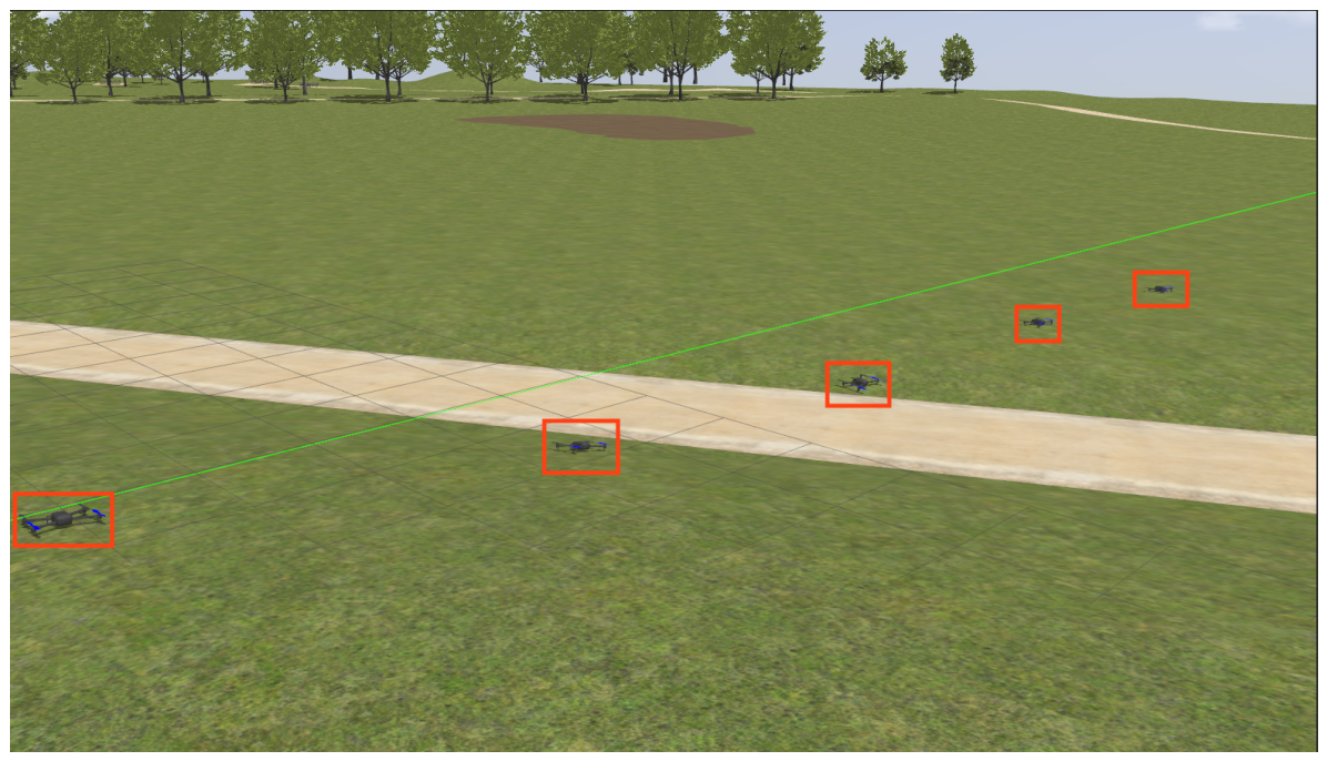
Figure 2 illustrates the operational environment of MUNILS. The figure confirms that five UAVs are successfully spawned at distinct initial coordinates and stably maintain a flight-ready state. This visually corroborates that multiple physical UAV instances can operate independently and simultaneously within a single machine environment. Building upon this verified architecture, subsequent evaluations were scaled up to large-scale swarms (up to 100 UAVs) to validate the platform’s robust scalability.

4.2.2. Network Isolation and Routing Verification

To validate the efficacy of the network namespace-based traffic isolation, a core technical contribution of this study, we analyzed the actual packet delivery pathways using the traceroute utility.
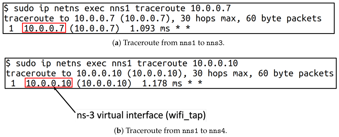
Figure 3a presents the route tracing results when an Internet Control Message Protocol (ICMP) packet is transmitted from the UAV residing in namespace nns1 (UAV 1) to a UAV in another namespace. The empirical results confirm that the packet strictly bypasses the host’s standard loopback interface and is accurately routed to the IP address (10.0.0.7) uniquely assigned to the destination UAV within the ns-3 simulation network. The measured response time was 1.093 milliseconds (ms).
This represents a significant and expected increase compared to typical localhost communication (approximately 0.05 ms), clearly demonstrating the realistic processing latency introduced by traversing the virtualized network stack. This verifies that the host operating system’s native network stack and the simulation traffic are strictly isolated, establishing a well-defined technical basis for accurately reflecting artificial communication delays or packet loss scenarios in subsequent algorithmic evaluations.
To verify the representativeness of this result, additional repeated traceroute experiments were conducted under the same configuration across multiple source–destination namespace pairs. Across all runs, the ICMP packets were consistently routed through the ns-3 virtual interface (wifi_tap), with measured response times tightly distributed around a mean of 1.118 ms. As a representative additional measurement, Figure 3b shows the result from nns1 to a different destination (10.0.0.10, 1.178 ms), illustrating the consistency of this routing behavior across destinations.

4.2.3. Flight Control Stability and Trajectory Verification

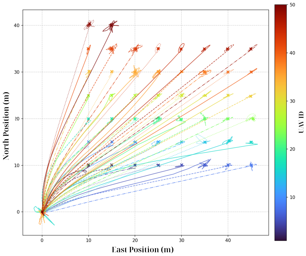
We verified the comprehensive end-to-end control performance of the platform by executing a large-scale multi-UAV cooperative control mission. A ROS2-based offboard control node was deployed to execute a scenario assigning distinct target waypoints, marked with an ‘X’ in Figure 4, to each of the 50 participating UAVs. This procedure actively verified the stability of the system’s bidirectional data flow under massive load. Figure 4 visualizes the 2-Dimensional (2D) actual flight odometry of the multiple UAVs receiving continuous control commands exclusively via the ns-3 network. As depicted in the figure, the 50 UAVs successfully took off from a consolidated starting point and navigated towards their distinct targets, moving stably without any path divergence or physical collisions. Notably, the flight trajectories near the target waypoints reveal highly realistic physical behaviors. Rather than stopping instantly upon reaching a target, the UAVs exhibit natural deceleration and rotation behaviors driven by simulated physical inertia and deceleration control logic. This sharply contrasts with conventional network simulators that treat positional movement as simple velocity vectors with instantaneous stops. This trajectory analysis demonstrates that the platform faithfully reflects the realistic acceleration and dynamic characteristics of the aircraft through its rigorous integration of Gazebo and PX4. Furthermore, evaluations confirmed that this trajectory stability is consistently maintained at even larger scales, such as 100 UAVs. The fact that the position control loop formed precise trajectories, despite all control traffic being mandatorily routed through the virtual network interface (wifi_tap) under such large-scale conditions, empirically demonstrates that the platform reliably supports closed-loop control across the physical, control, and network layers. The visual representation of the 100-UAV trajectory is omitted for brevity, as it exhibits a stable navigation pattern highly analogous to that of the 50-UAV case shown in Figure 4.

4.2.4. Time Synchronization Accuracy

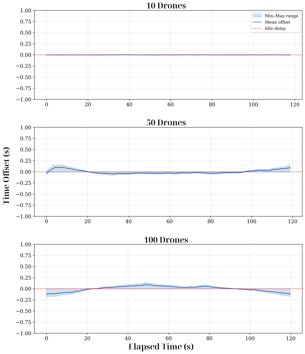
Finally, we evaluated the cross-layer time synchronization performance across the integrated simulators under varying load conditions. In this evaluation, Gazebo’s simulation clock serves as the master reference. We quantified the synchronization integrity by calculating the time offset. In this context, the time offset represents the temporal difference, or synchronization error, between this master clock and the local execution times of the ns-3, ROS2, and PX4 modules. Figure 5 presents the time-series variation of this time offset, including the min-max range and mean value, for 10, 50, and 100 UAV scenarios over a 120-s simulation period. In the 10-UAV scenario, the offset tightly converges to zero, demonstrating near-perfect alignment. While the min-max range of the offset expands as the scale increases to 50 and 100 UAVs due to the extreme computational load on a single machine, the mean offset strictly tracks zero without cumulative clock drift.
The expansion of the min-max range under heavier loads reflects instantaneous scheduling jitter from the host OS scheduler under near-saturated CPU conditions, while the consistently near-zero mean offset confirms that the master-slave architecture in Section 3.3 prevents these transient perturbations from accumulating into systemic drift. This confirms that the global synchronization mechanism effectively maintains temporal integrity among the heterogeneous modules, validating the platform’s reliability for large-scale multi-UAV operations.
Several aspects of this oscillating behavior warrant further clarification. First, the observed ± 0.10 s offset range is engineering-negligible for the inter-UAV cooperative control regime targeted by MUNILS, which typically operates at 1–5 Hz, while high-rate intra-UAV attitude control is processed through namespace loopback and is unaffected by this offset. Second, extended measurements beyond the 120-s window confirmed that the bounded oscillation persists without converging to or diverging from any limit, consistent with a non-cumulative regime. Third, the oscillation arises from the dynamic interaction between Gazebo’s real-time factor under a bursty computational load and the catch-up behavior of the subordinated ROS2, PX4, and ns-3 modules; because the master clock enforces a convergence boundary, this manifests as bounded oscillation rather than systemic drift. Finally, additional experiments scaling up to 150 UAVs reproduced the same bounded oscillation and rapid recovery from transient RTF dips, whereas scenarios beyond this scale could not be verified due to the hardware limits of the machine specified in Section 4.1.1, indicating the practical upper bound of single-machine operation.

5. Conclusions

This paper proposed MUNILS, a comprehensive platform integrating Gazebo, PX4, and ns-3 via ROS2 middleware, featuring complete traffic isolation through Linux network namespaces. By implementing a dual-path traffic routing mechanism and a global time synchronization architecture, we successfully addressed the lack of network-physical interaction modeling and the temporal mismatches inherent in existing co-simulation frameworks. Experimental validation confirmed strict network path isolation and robust system scalability, successfully executing large-scale swarm operations (e.g., up to 100 UAVs) on a single machine while maintaining a near-zero mean time offset without cumulative clock drift across all integrated modules. Consequently, the proposed platform serves as a reliable tool for the rigorous pre-deployment verification of complex, large-scale missions involving high costs and risks.
In future work, we plan to integrate next-generation communication models, such as 5G/6G and satellite networks, to evaluate advanced control strategies for emerging Urban Air Mobility (UAM) scenarios.

Author Contributions

Conceptualization, W.L.; methodology, W.L. and S.L.; software, S.L.; validation, S.L., G.Y. and D.L.; formal analysis, S.L. and W.L.; investigation, S.L. and G.Y.; resources, W.L.; data curation, S.L. and D.L.; writing—original draft preparation, S.L.; writing—review and editing, S.L. and W.L.; visualization, S.L.; supervision, W.L.; project administration, W.L.; funding acquisition, W.L. All authors have read and agreed to the published version of the manuscript.

Funding

This work was supported by Korea Research Institute for defense Technology planning and advancement (KRIT)-Grant funded by Defense Acquisition Program Administration (DAPA) (KRIT-CT-23-041).

Institutional Review Board Statement

Not applicable.

Informed Consent Statement

Not applicable.

Data Availability Statement

The data used to support the findings of this study are available from the corresponding author upon reasonable request and with permission of the funders.

Conflicts of Interest

The authors declare no conflicts of interest.

Abbreviations

The following abbreviations are used in this manuscript:
2D2-Dimensional
AMDAdvanced Micro Devices
APIApplication Programming Interface
DDR5Double Data Rate 5
DDSData Distribution Service
DESDiscrete-Event Simulator
GHzGigahertz
GPUGraphics Processing Unit
ICMPInternet Control Message Protocol
LTSLong-Term Support
MAVLinkMicro Air Vehicle Link
MUNILSMulti-UAV Network-in-the-Loop Simulation
NNSNetwork Namespace
RFRadio Frequency
ROS2Robot Operating System 2
RTFReal-Time Factor
SDFSimulation Description Format
SITLSoftware-In-The-Loop
TCPTransmission Control Protocol
UAMUrban Air Mobility
UAVUnmanned Aerial Vehicle
UDPUser Datagram Protocol
vethVirtual Ethernet
XRCE-DDSeXtremely Resource Constrained Environments - Data Distribution Service

References

  1. Lee, W. Federated Reinforcement Learning-Based UAV Swarm System for Aerial Remote Sensing. Wirel. Commun. Mob. Comput. 2022, 2022, 4327380. [Google Scholar] [CrossRef] [Scilit]
  2. Yoo, S.; Lee, W. Federated reinforcement learning based AANs with LEO satellites and UAVs. Sensors 2021, 21, 8111. [Google Scholar] [CrossRef] [Scilit] [PubMed]
  3. Lee, W. Enabling reliable UAV control by utilizing multiple protocols and paths for transmitting duplicated control packets. Sensors 2021, 21, 3295. [Google Scholar] [CrossRef] [Scilit] [PubMed]
  4. Lee, W.; Lee, J.Y.; Joo, H.; Kim, H. An MPTCP-based transmission scheme for improving the control stability of unmanned aerial vehicles. Sensors 2021, 21, 2791. [Google Scholar] [CrossRef] [Scilit] [PubMed]
  5. Chen, Z.; Yan, J.; Ma, B.; Shi, K.; Yu, Q.; Yuan, W. A survey on open-source simulation platforms for multi-copter UAV swarms. Robotics 2023, 12, 53. [Google Scholar] [CrossRef] [Scilit]
  6. Dey, E.; Hossain, J.; Roy, N.; Busart, C. Synchrosim: An integrated co-simulation middleware for heterogeneous multi-robot system. In Proceedings of the 2022 18th International Conference on Distributed Computing in Sensor Systems (DCOSS); IEEE: Piscataway, NJ, USA, 2022; pp. 334–341. [Google Scholar]
  7. Macenski, S.; Foote, T.; Gerkey, B.; Lalancette, C.; Woodall, W. Robot operating system 2: Design, architecture, and uses in the wild. Sci. Robot. 2022, 7, eabm6074. [Google Scholar] [CrossRef] [Scilit] [PubMed]
  8. eProsima. Micro XRCE-DDS Documentation. 2026. Available online: https://micro-xrce-dds.docs.eprosima.com/ (accessed on 24 March 2026).
  9. Meier, L.; Honegger, D.; Pollefeys, M. PX4: A node-based multithreaded open source robotics framework for deeply embedded platforms. In Proceedings of the 2015 IEEE International Conference on Robotics and Automation (ICRA); IEEE: Piscataway, NJ, USA, 2015; pp. 6235–6240. [Google Scholar]
  10. Koenig, N.; Howard, A. Design and use paradigms for gazebo, an open-source multi-robot simulator. In Proceedings of the 2004 IEEE/RSJ International Conference on Intelligent Robots and Systems (IROS) (IEEE Cat. No. 04CH37566); IEEE: Piscataway, NJ, USA, 2004; Volume 3, pp. 2149–2154. [Google Scholar]
  11. Riley, G.F.; Henderson, T.R. The ns-3 network simulator. In Modeling and Tools for Network Simulation; Springer: Berlin/Heidelberg, Germany, 2010; pp. 15–34. [Google Scholar]
  12. Kim, W.; Luong, T.; Ha, Y.; Doh, M.; Yax, J.F.M.; Moon, H. High-fidelity drone simulation with depth camera noise and improved air drag force models. Appl. Sci. 2023, 13, 10631. [Google Scholar] [CrossRef] [Scilit]
  13. Ma, C.; Zhou, Y.; Li, Z. A new simulation environment based on AirSim, ROS, and PX4 for quadcopter aircrafts. In Proceedings of the 2020 6th International Conference on Control, Automation and Robotics (ICCAR); IEEE: Piscataway, NJ, USA, 2020; pp. 486–490. [Google Scholar]
  14. Shah, S.; Dey, D.; Lovett, C.; Kapoor, A. Airsim: High-fidelity visual and physical simulation for autonomous vehicles. In Proceedings of the Field and Service Robotics: Results of the 11th International Conference; Springer: Piscataway, NJ, USA, 2017; pp. 621–635. [Google Scholar]
  15. Su, Y.; Chen, Y.; Yi, S.; Feng, H.; Xu, Y.; Xiang, W.; Hu, B. A Modular and Scalable Simulator for Connected-UAVs Communication in 5G Networks. In Proceedings of the 2025 International Conference on Modeling, Analysis and Simulation of Wireless and Mobile Systems (MSWiM); IEEE: Piscataway, NJ, USA, 2025; pp. 725–729. [Google Scholar]
  16. Keller, S.; Andre, J.; Wiedner, F. Simulation of wifi mesh networks with mobile nodes. Network 2021, 1, 1–4. [Google Scholar] [CrossRef]
  17. NPS-ROS2. ns3_gazebo: Simulate ROS2 Network Behavior Using ns-3 and Gazebo. 2026. Available online: https://github.com/nps-ros2/ns3_gazebo (accessed on 27 February 2026).
  18. Acharya, S.; Bharadwaj, A.; Simmhan, Y.; Gopalan, A.; Parag, P.; Tyagi, H. Cornet: A co-simulation middleware for robot networks. In Proceedings of the 2020 International Conference on COMmunication Systems & NETworkS (COMSNETS); IEEE: Piscataway, NJ, USA, 2020; pp. 245–251. [Google Scholar]
  19. Quigley, M.; Conley, K.; Gerkey, B.; Faust, J.; Foote, T.; Leibs, J.; Wheeler, R.; Ng, A.Y. ROS: An open-source Robot Operating System. In Proceedings of the ICRA Workshop on Open Source Software, Kobe, Japan; IEEE: Piscataway, NJ, USA, 2009; Volume 3, p. 5. [Google Scholar]
  20. Ponniah, J.; Dantsker, O.D.; Mancuso, R. Design of Multi-Agent UAV Simulator to Support the Development of the MARSNet Communication Protocol. In Proceedings of the AIAA Aviation 2019 Forum; AIAA: Reston, Virginia, 2019; p. 3114. [Google Scholar]
  21. Park, S.; La, W.G.; Lee, W.; Kim, H. Devising a distributed co-simulator for a multi-UAV network. Sensors 2020, 20, 6196. [Google Scholar] [CrossRef] [Scilit] [PubMed]
  22. Moon, S.; Bird, J.J.; Borenstein, S.; Frew, E.W. A gazebo/ros-based communication-realistic simulator for networked suas. In Proceedings of the 2020 International Conference on Unmanned Aircraft Systems (ICUAS); IEEE: Piscataway, NJ, USA, 2020; pp. 1819–1827. [Google Scholar]
  23. Koubâa, A.; Allouch, A.; Alajlan, M.; Javed, Y.; Belghith, A.; Khalgui, M. Micro air vehicle link (mavlink) in a nutshell: A survey. IEEE Access 2019, 7, 87658–87680. [Google Scholar] [CrossRef] [Scilit]
  24. IEEE Std 1516-2010; IEEE Standard for Modeling and Simulation (M&S) High Level Architecture (HLA)—Framework and Rules. (Revision of IEEE Std 1516-2000). IEEE: Piscataway, NJ, USA, 2010. [CrossRef] [Scilit]
  25. Open Source Robotics Foundation. Gazebo Classic: Physics Parameters Tutorial. 2026. Available online: https://classic.gazebosim.org/tutorials?tut=physics_params (accessed on 7 May 2026).
  26. Hayat, S.; Yanmaz, E.; Muzaffar, R. Survey on Unmanned Aerial Vehicle Networks for Civil Applications: A Communications Viewpoint. IEEE Commun. Surv. Tutor. 2016, 18, 2624–2661. [Google Scholar] [CrossRef] [Scilit]
  27. IEEE Std 802.11-2020; IEEE Standard for Information Technology—Telecommunications and Information Exchange between Systems-Local and Metropolitan Area Networks–Specific Requirements-Part 11: Wireless LAN Medium Access Control (MAC) and Physical Layer (PHY) Specifications. (Revision of IEEE Std 802.11-2016). IEEE: Piscataway, NJ, USA, 2021. [CrossRef] [Scilit]
Figure 1. Overall architecture and traffic routing mechanism of the MUNILS platform.
Drones 10 00387 g001
Figure 2. MUNILS environment setup featuring five Iris UAVs deployed in the Gazebo baylands world.
Drones 10 00387 g002
Figure 3. Network path verification across multiple destinations (nns3: 10.0.0.7, nns4: 10.0.0.10), confirming traffic routing through the ns-3 virtual interface.
Drones 10 00387 g003
Figure 4. 2D flight trajectories of 50 UAVs navigating to distinct waypoints via the isolated virtual network.
Drones 10 00387 g004
Figure 5. Time-series analysis of the clock synchronization offset across 10, 50, and 100 UAV scenarios.
Drones 10 00387 g005
Table 1. Comparison of supported and unsupported features between the proposed MUNILS platform and representative prior co-simulation frameworks. “O” denotes a supported feature, and “X” denotes an unsupported one.
Featurens3_gazebo [17]CORNET [18]Ponniah et al. [20]MUNILS (Ours)
ROS2 SupportOXXO
PX4 IntegrationXOXO
Network-in-the-LoopOOOO
Kernel-level Traffic IsolationXXXO
Cross-layer Time SynchronizationXXXO
Automated Multi-UAV OrchestrationXXXO
Disclaimer/Publisher’s Note: The statements, opinions and data contained in all publications are solely those of the individual author(s) and contributor(s) and not of MDPI and/or the editor(s). MDPI and/or the editor(s) disclaim responsibility for any injury to people or property resulting from any ideas, methods, instructions or products referred to in the content.