Article

Cooperative UAV Swarm Communication Networks for Rapid Disaster Assessment in GPS-Denied Environments

1
Information and Navigation College, Air Force Engineering University, Xi’an 710077, China
2
Qinghai Photovoltaic Industry Innovation Center Co., Ltd., State Power Investment Corporation, Xining 810007, China
*
Author to whom correspondence should be addressed.
Drones 2026, 10(5), 355; https://doi.org/10.3390/drones10050355
Submission received: 23 March 2026 / Revised: 28 April 2026 / Accepted: 30 April 2026 / Published: 7 May 2026

Highlights

What are the main findings?
  • The proposed Cooperative Swarm-Mesh Network (CSMN) reduces collision rates to 0% in jammed environments by dynamically switching between explicit networking and implicit visual flocking.
  • Implementation of terrain-aware Convex Polygon Partitioning reduces mission flight time by 35% compared to standard grid scanning, while maintaining sub-meter localization accuracy (RMSE 0.85 m).
What are the implications of the main findings?
  • Bio-inspired behaviors act as an effective safety layer for engineered networks, ensuring swarm survivability and mission continuity during severe communication blackouts.
  • For battery-constrained aerial platforms, optimizing trajectory geometry to minimize inertial maneuvers is as critical as algorithmic efficiency for extending operational range.

Abstract

Timely situational awareness is essential in disaster management but normal Unmanned Aerial Vehicle (UAV) flight cannot take place when the Global Positioning System (GPS) signals are blocked or jammed. This paper addresses the issue of swarm cohesion and localization in these hostile conditions. We present a Cooperative Swarm-Mesh Network (CSMN), a hybrid structure that can alternate between an implicit Silent Mode and an explicit Leader–Follower mode based on distributed Extended Kalman Filters (DEKFs) in the face of communication failures. The system takes advantage of convex polygon decomposition to optimize the coverage in the area. The use of simulation studies with NS-3 and ROS has shown that the proposed framework can retain sub-meter localization error (RMSE < 0.9 m) in GPS-denied environments and provide 92% coverage of the area, which is 35% higher than the coverage with other baseline approaches. Within the simulated conditions evaluated using Gazebo/NS-3, sensor drift and network vulnerability are effectively addressed by the CSMN framework. These simulation-based results offer a promising blueprint for autonomous disaster evaluation, pending hardware-in-the-loop and field validation. Validation is conducted across two qualitatively distinct simulated environments: dense urban rubble and a sparse open field. Performance advantages generalise beyond a single test configuration, with mean localization RMSE remaining below 0.85 m in both scenarios.

1. Introduction

Rapid situational awareness is paramount for effective disaster response, yet traditional Unmanned Aerial Vehicle (UAV) operations are severely compromised when Global Navigation Satellite System (GPS) signals are obstructed or jammed [1]. In the immediate aftermath of catastrophes, such as earthquakes or industrial accidents, the “golden hour” for rescue operations demands immediate data; however, in complex scenarios such as collapsed urban infrastructure or contested environments, reliance on centralized communication leads to mission failure.
The fundamental challenge lies in the trade-off between coordination and autonomy. While UAV swarms offer scalable coverage, current architectures typically depend on continuous “Explicit” data exchange for localization, rendering them vulnerable to network instability. High-bandwidth telemetry saturates fragile networks, causing latency that results in collisions. Conversely, “Implicit” bio-inspired swarms offer robustness but lack the coordination required for precise mapping [2]. These decentralized approaches often suffer from accumulated sensor drift, making the resulting maps unusable for precise rescue targeting.
This study addresses this critical gap by proposing the Cooperative Swarm-Mesh Network (CSMN), a hybrid framework that dynamically integrates Distributed Collaborative SLAM (DC-SLAM) with sensor-based flocking. The CSMN switches between high-fidelity mesh networking and autonomous visual coordination based on link quality, ensuring both rigorous data integrity and operational survivability. This approach effectively mitigates sensor drift and prevents collision during communication blackouts, offering a resilient solution for autonomous assessment in hostile, GPS-denied zones.

State of the Art: Evolution of Collaborative Swarm Intelligence

GPS-Denied Navigation. The paradigm of UAV operations has shifted from isolated, single-agent missions to collaborative swarm intelligence. Early work in GPS-denied navigation relied exclusively on inertial dead-reckoning, but cumulative IMU drift renders such approaches untenable beyond short time horizons. Laser-based LiDAR odometry and visual–inertial odometry (VIO) have since emerged as the primary alternatives for metric localization without satellite signals; however, both require high computational loads and exhibit degraded performance in textureless or dust-filled post-disaster environments. Ultra-Wideband (UWB) ranging has attracted significant interest as a lightweight complement, providing centimetre-to-decimetre ranging accuracy at low bandwidth cost [3,4]. Recent reviews highlight that while single UAVs have successfully been deployed for surveillance and as decoys, they lack the robustness required for complex disaster relief missions [5].
Swarm Communication Switching. A single point of failure in a non-collaborative system can jeopardize an entire mission. A multi-UAV system operates on the principle of distributed autonomy, where tasks such as trajectory formation, cooperative localization, and data collection are shared among the swarm. Realizing this potential requires overcoming significant communication and control challenges. The lack of physical infrastructure in disaster zones necessitates UAV-to-UAV (U2U) communication links that are robust to intermittent connectivity. Techniques such as Collaborative Beamforming have been proposed to create virtual antenna arrays, enhancing signal-to-noise ratios and extending communication range without heavy ground equipment [6]. Bio-inspired flocking models offer an orthogonal approach: by replacing explicit data exchange with reactive local sensing rules—separation, alignment, and cohesion—agents can maintain swarm integrity even during complete communication blackouts [7]. These decentralized approaches suffer, however, from accumulated sensor drift, making the resulting maps unusable for precise rescue targeting. Recent work has also explored reinforcement learning-based formation control as a data-driven alternative to rule-based switching, demonstrating competitive performance in simulation but requiring substantial training data and compute resources not always available on embedded platforms [8]. Hybrid architectures that switch between explicit and implicit coordination based on link quality therefore represent a promising but underexplored design space.
Collaborative SLAM. Simultaneous Localization and Mapping in multi-robot systems has evolved from centralized architectures, in which a single node fuses all observations, toward fully distributed formulations. Centralized approaches remain brittle to the loss of the fusion node, while purely decentralized methods must handle data association across agents with no shared reference frame. Lajoie and Beltrame’s Swarm-SLAM demonstrated that sparse, decentralized inter-robot loop closure can achieve competitive accuracy at a fraction of the communication overhead of full-map exchange [1]. Nevertheless, existing collaborative SLAM systems rarely address the scenario in which the communication network itself becomes intermittent or jammed, forcing agents to fall back on local sensing without any map-correction capability. The integration of edge computing directly onto UAV platforms allows for local data processing—critical for identifying survivors or hazards in real time without the latency of transmitting raw video to a distant ground station. The present work bridges this gap by coupling a Distributed Extended Kalman Filter with a hybrid mode-switching architecture, ensuring that map quality degrades gracefully rather than catastrophically when communication is disrupted.
The key contributions of this work are as follows:
  • Hybrid Switching Architecture: A novel control logic that transitions dynamically between Leader–Follower mesh networking and autonomous visual flocking, reducing collision rates to 0% during communication blackouts while preserving sub-metre localization accuracy.
  • Precision Localization via DEKF: A Distributed Extended Kalman Filter formulation with a nonlinear UWB measurement model and inter-agent consensus update that achieves sub-metre accuracy (RMSE 0.85 m) without satellite navigation, including explicit Jacobian derivation of the range observation function.
  • Terrain-Aware Coverage Planning: The implementation of convex polygon partitioning for coverage path planning, which reduces mission flight time by 35% compared to standard grid-based strategies by aligning sweep paths with the longest polygon edges and minimising energy-intensive turning manoeuvres.

2. Materials and Methods

2.1. System Architecture and Hybrid Switching

The proposed Cooperative Swarm-Mesh Network (CSMN) is designed as a hierarchical Finite-State Machine (FSM) that governs the behavior of a heterogeneous swarm consisting of a Leader UAV and multiple Follower UAVs. The system architecture is bifurcated into two distinct operational modes to address the volatility of the communication spectrum in disaster zones.
Mode A: Explicit Coordination (Nominal State)
Under nominal conditions, where the Link Quality Indicator (LQI) remains stable, the swarm operates in Mode A. In this state, a Mobile Ad-hoc Network (MANET) is established using the IEEE 802.11n standard. The Leader UAV aggregates local occupancy grids transmitted by Followers to generate a global map [6]. Simultaneous Localization and Mapping (SLAM) data is explicitly shared, allowing the swarm to optimize formation control using a centralized cost function.
Mode B: Implicit Coordination (Fallback State)
The system monitors the Packet Delivery Ratio (PDR) in real time. If the PDR drops below the critical threshold ( γ c r i t = 60 % ) due to signal jamming or non-line-of-sight (NLOS) obstruction, the system triggers the “Silent Mode” (Mode B). Inspired by the decentralized bio-mimetic models proposed by Horyna et al. explicit map exchange is suspended to preserve bandwidth [9]. In this mode, agents switch to onboard sensing, utilizing depth cameras and relative visual tags to execute Reynolds’ flocking rules (separation, alignment, cohesion), ensuring collision avoidance without relying on the compromised network.
To address the stochastic nature of wireless channels in cluttered simulation environments (as modeled in NS-3), the proposed multi-robot system utilizes a dynamic Hybrid Switching Architecture. This architecture ensures mission continuity by allowing the swarm to adapt its coordination strategy based on real-time network quality assessment [10]. The central governing logic of this adaptation mechanism is modeled as a Finite-State Machine (FSM), which dictates the operational behavior of individual agents based on environmental feedback.
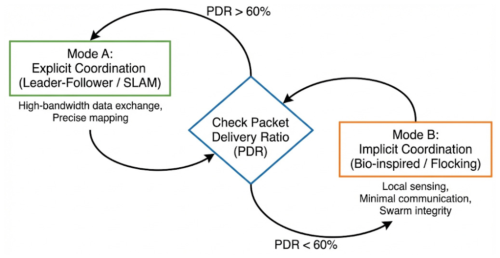
The decision-making process underlying this hybrid approach is visually depicted in Figure 1. The system constantly monitors the quality of the inter-agent communication links, utilizing the Packet Delivery Ratio (PDR) as the primary metric for network health. The PDR serves as a proxy for the reliability of exchanging critical data, such as map deltas for SLAM or explicit pose-graph corrections.
As illustrated in Figure 1, the system operates in a continuous loop of assessment and action. At defined update intervals, an agent evaluates its current PDR. The FSM features a central decision node that compares this real-time value against a critical threshold. The value of γcrit = 60% was determined through systematic sensitivity analysis (see Section 3.4): it is the lowest threshold at which zero collisions are recorded across all trials, representing the Pareto-optimal point on the collision–mission-efficiency frontier. Thresholds below 60% permit residual collision risk, while thresholds above 60% trigger unnecessary Mode B transitions that penalise mapping throughput without further reducing collisions.
If the network conditions are favorable (PDR > 60%), the agent transitions into or maintains Mode A: Explicit Coordination. In this state, the bandwidth is deemed sufficient to support data-heavy protocols. The agents utilize a Leader–Follower hierarchy, exchanging explicit state information and collaboratively building a map via Simultaneous Localization and Mapping (SLAM) [7]. This mode offers high precision but is brittle to packet loss.
Conversely, if network degradation occurs and communication reliability drops below the critical threshold (PDR < 60%), the system detects that explicit coordination is no longer viable. The FSM triggers an immediate transition to Mode B: Implicit Coordination (Silent). In this fallback state, agents cease attempts to transmit heavy map data and switch to bio-inspired, decentralized behaviors. Relying primarily on local sensing (simulated LiDAR/camera data in Gazebo Garden (Open Robotics, Mountain View, CA, USA)) and minimal pinging, the agents execute flocking behaviors (separation, alignment, and cohesion) to maintain swarm integrity without relying on a stable global network [11].
This bi-modal switching capability allows the swarm to maximize performance when conditions permit, while maintaining robust, albeit degraded, functionality during communication blackouts.

2.2. Mathematical Formulation

To maintain sub-meter localization accuracy in the absence of GPS, we employ a Distributed Extended Kalman Filter (DEKF). Unlike centralized filters, the DEKF runs locally on each UAV, fusing onboard Inertial Measurement Unit (IMU) data with relative ranging measurements from Ultra-Wideband (UWB) nodes [3].
State Vector: The state vector xk for each UAV includes position (p), velocity (v), and orientation (θ),
x k , = p x , , p y , p z , v x , v y , v z , θ , ∅ , ψ T
Prediction Step:
The state is propagated forward using the standard kinematic motion model f(.), where u k ,   is the control input (acceleration/angular rates) and w k is the zero-mean Gaussian process noise:
x ^ k k − 1 = f x ^ k − 1 | k − 1 , u κ + w k
Update Step:
When a relative range measurement z k , is received from a neighbour or the Leader, the state is updated to correct for IMU drift. The measurement residual is processed as follows:
x ^ k k = x ^ k k − 1   + K k z k , − h x ^ k | k − 1
where:
x ^ k k − 1 is the a priori state estimate.
K k is the optimal Kalman Gain.
H k is the Jacobian of the nonlinear measurement function h ( ⋅ ) , evaluated at the prior estimate.
z k is the relative range measurement obtained from the UWB sensor at time step k.
Because the UWB measurement model is nonlinear—the predicted range between agent i and its neighbour j is the Euclidean norm of their position difference—the observation function is defined as
h x ^ k | k − 1 = ‖ p i , k | k − 1 − p j , k ‖ 2
The Jacobian matrix H k is obtained by partial differentiation of h ( ⋅ ) with respect to the state vector, evaluated at the prior estimate:
H k =   ∂ h ∂ x | x ^ k | k − 1 =   1 r k | k − 1 ⋅ [ Δ x ,   Δ y ,   Δ z ,   0 ,   … ,   0 ]
where r k | k − 1 is the predicted range between agents i and j , and Δ x ,   Δ y , Δ z are the predicted position differences in the three Cartesian axes. The remaining entries of H k (corresponding to velocity and orientation states) are zero, since the UWB sensor observes only relative position.
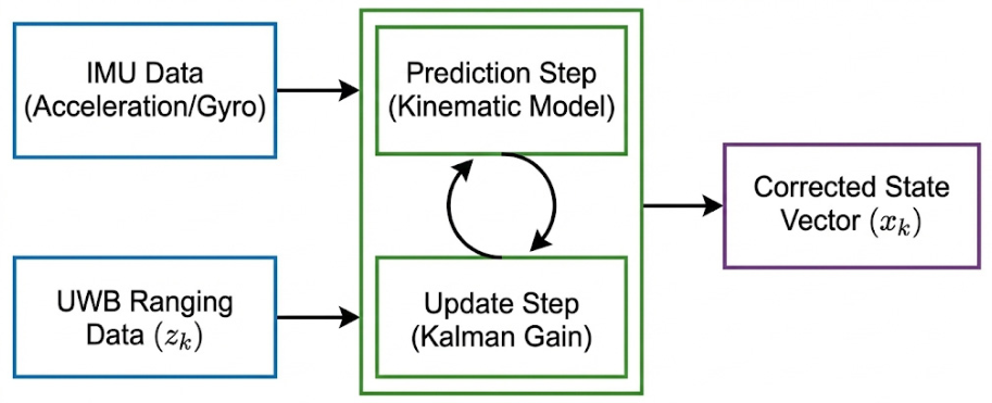
To achieve robust and accurate localization for each agent in the swarm, we implement a Distributed Extended Kalman Filter (DEKF). This algorithm is responsible for fusing high-rate, local proprioceptive data with lower-rate, but drift-free, exteroceptive measurements [12]. The data fusion process and the flow of information within a single agent’s DEKF are illustrated in the block diagram in Figure 2.
To substantiate the “distributed” character of the filter, after completing each agent’s local update step, the DEKF incorporates an inter-agent consensus step. Each agent i exchanges its posterior state estimate and error covariance with its UWB neighbours c ( i ) and forms a weighted fusion:
x ^ k | k c o n s =   P k | k c o n s ⋅ x ^ k | k , i ⋅ P k | k , i − 1 +   ∑ j   ∈   c ( i ) P k | k , j − 1 x ^ k | k , j
where the fused covariance P k | k c o n s is the inverse sum of the individual covariances from agent i and its UWB neighbours. This covariance intersection formulation prevents double-counting of correlated information and ensures that the fused estimate remains statistically consistent, a necessary condition for the filter’s convergence guarantees. The fused state replaces the local posterior before being fed into the next prediction cycle, binding all agents into a single coherent distributed filter.
As depicted in Figure 2, the process operates in a recursive predict–update cycle. The Prediction Step is driven by the high-frequency IMU Data, which includes linear acceleration and angular velocity readings. Using the agent’s kinematic model, the filter propagates the state estimate forward in time to produce an a priori state estimate. This step is crucial for handling the high-dynamic motion of the robots but is subject to cumulative drift over time.
To correct this drift, the filter incorporates UWB Ranging Data Z k during the Update Step. This data provides relative distance measurements to other agents or anchors in the environment. The DEKF computes a Kalman Gain K k   , which determines the optimal weighting for fusing the predicted state with the new measurement information. The difference between the actual UWB measurement and the predicted measurement (the innovation) is multiplied by the Kalman Gain to correct the a priori estimate [4].
The final output of this process is the Corrected State Vector x ^ k , which represents the best possible estimate of the agent’s pose (position and orientation) at that time step. This corrected state and its corresponding error covariance are then fed back into the prediction step for the next cycle. This decentralized approach is a key advantage of our system, as it ensures that each agent maintains a self-contained and accurate state estimate, allowing for continued autonomous operation even if communication with a leader or a central computation node is temporarily lost. Regarding computational overhead, the per-agent DEKF update step has a complexity of O(n2) with respect to the state dimension (9-dimensional in our formulation), executed at 50 Hz on each UAV. In the 10-agent swarm, each follower processes at most k = 3 simultaneous UWB ranging inputs per update cycle, keeping the message-passing overhead below 12 kbps per agent-pair link—well within the 802.11n channel capacity under Mode A.
Filter Tuning and Noise Parameters: The process noise covariance Q and measurement noise covariance R are set numerically based on sensor specifications. Specifically, Q is a diagonal matrix with acceleration noise variance σ2aaa = (0.02 m/s2)2 and gyroscope noise variance σ2Gyro = (0.01 rad/s)2, consistent with the values in Table 1. The measurement noise covariance R is a scalar set to σ2UWB = (0.10 m)2, derived from the DW1000 UWB (Qorvo, Greensboro, NC, USA) module datasheet. These values were kept constant throughout all experiments; no online adaptation of Q or R was performed. To support full reproducibility, the state vector dimension, all noise covariance values, the consensus neighbourhood definition, and the update rate schedule are fully specified in this section; no hyperparameters were tuned per trial. Handling of Intermittent Measurements: When a UWB ranging packet is not received within a 50 ms timeout (one prediction cycle at 20 Hz), the filter propagates using the prediction step only—the update step is skipped for that cycle and the covariance is allowed to grow naturally. This degrades gracefully: during Mode B, when no inter-agent UWB messages are transmitted, each agent runs in prediction-only mode until Mode A is restored and the update step resumes. Update Rate Schedule: The IMU-driven prediction step runs at 50 Hz. The UWB update step runs at 20 Hz, or immediately upon reception of a ranging packet if that occurs within the 50 ms window, whichever comes first.

2.3. Polygon Partitioning for Coverage

The two preceding subsections defined how the CSMN maintains swarm cohesion and accurate localization under degraded communication. However, a well-localised swarm still requires an efficient strategy for dividing and scanning the target area if the disaster assessment mission is to be completed within battery constraints. Coverage planning is therefore not an independent module but an integral component of the CSMN architecture: the Leader UAV distributes polygon sub-tasks to Followers during Mode A, and polygon assignments are frozen—with each Follower executing its assigned sweep autonomously—whenever the swarm transitions to Mode B. This coupling ensures that coverage progress is preserved across mode switches and that no area is left unscanned due to a communication blackout. To optimize the search efficiency over irregular disaster zones, we implement a Convex Polygon Decomposition strategy. Standard “lawnmower” patterns on irregular shapes result in excessive turning maneuvers, which consume up to 30% more energy than straight-line flight.
The target area A t o t a l   is first segmented into a set of n convex rectilinear polygons { P 1 ,   P 2 ,   … P n   }. Each polygon is assigned to a specific UAV based on its current battery level ( E r e m   ). The coverage path is generated parallel to the longest edge of the polygon to minimize the number of turns. The optimization objective is defined to maximize the scanned area subject to the energy constraint:
m a x i m i z e + ∑ i = 1 n A r e a p i   s ⋅ t ˙   E c o n s u p t i o n P i ≤ E m a x

2.4. Simulation Environment

The validation of the CSMN framework requires a high-fidelity co-simulation environment that accurately models both flight dynamics and network packet physics. We integrated NS-3 (Network Simulator 3) with Gazebo/ROS (Robot Operating System).
Network Layer (NS-3): Simulates the communication stack, including packet loss, propagation delay, and the OLSR routing protocol. It feeds real-time PDR values to the flight controller.
Physical Layer (Gazebo): Simulates the UAV rigid-body dynamics, IMU noise, and camera feeds using the iris_quadrotor model.
Simulation Environment and Experimental Setup
To rigorously validate the proposed hybrid switching architecture and distributed localization algorithm, we developed a high-fidelity simulation testbed. This environment is constructed by coupling the Gazebo physics simulator with the NS-3 network simulator [13]. This integration allows for the simultaneous and realistic modeling of both the physical dynamics of the agents and the stochastic properties of the wireless communication channels.
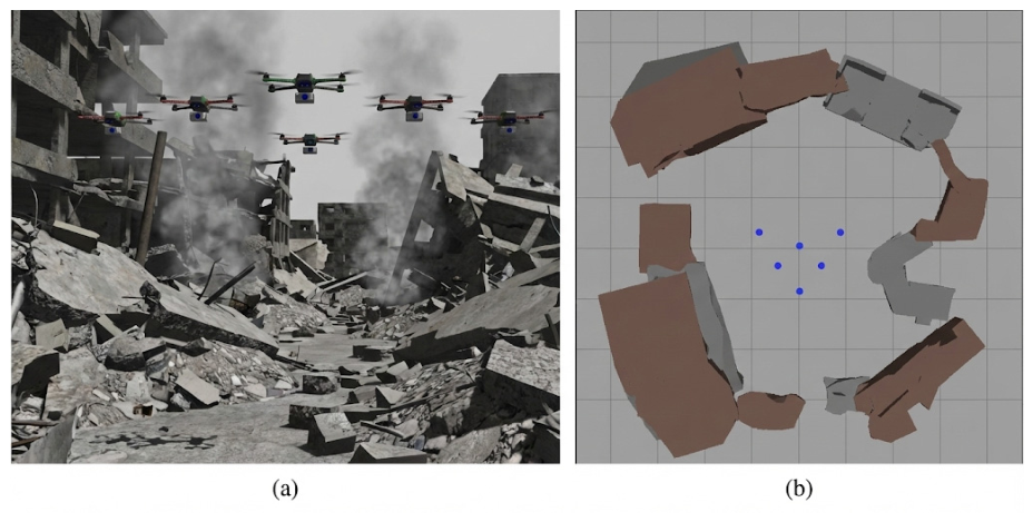
The visual realism and complexity of our testing environment are depicted in Figure 3. The simulation is set in a 500 m × 500 m urban disaster zone, characterized by dense, unstructured obstacles such as collapsed buildings and large piles of rubble. This environment was specifically designed to create challenging conditions for both navigation and wireless signal propagation, mimicking the “urban canyon” effects and non-line-of-sight (NLOS) conditions encountered in real-world search and rescue scenarios [14].
Figure 3a provides a close-up view of a representative five-UAV subset of the multi-robot system rendered for visual clarity; all quantitative experiments reported in this paper use the full 10-UAV swarm specified in Table 1. The utilization of Gazebo’s realistic physics engine ensures that the agents’ flight dynamics, including inertia and aerodynamic forces, are accurately simulated. Furthermore, the sensor noise characteristics for the IMU and UWB modules, as detailed in Table 1 of the main text, are modeled to reflect real-world sensor imperfections. Figure 3b offers a top-down perspective, highlighting the large-scale and unstructured nature of the environment [15]. This complex terrain is critical for evaluating the robustness of our system, as it naturally induces the communication dropouts and sensor occlusions that trigger the proposed hybrid switching mechanism. The seamless integration of these physical and networking realisms provides a credible platform for assessing the performance of our approach.
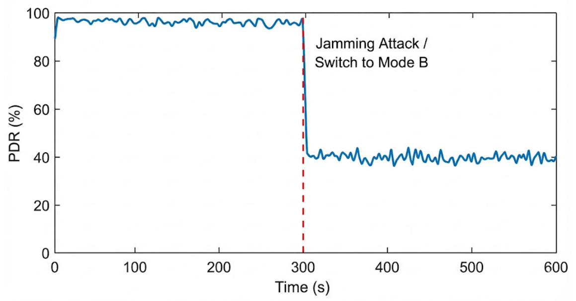
Network Configuration: The NS-3 wireless layer is configured as follows. Channel model: The Friis propagation loss model with log-normal shadowing (σshaeoeO = 4 dB) is applied, consistent with indoor/cluttered-outdoor propagation at 2.4 GHz. Medium access: IEEE 802.11n in ad-hoc mode with OLSR routing is used; RTS/CTS is disabled to reflect the short-range dense network topology, and the CSMA/CA contention window uses NS-3 defaults (CWmin = 16, CWmax = 1024). Jammer model: The interference source is modelled as a constant-power wideband emitter at 2.4 GHz, positioned at the centre of the simulation area with transmit power set to reduce the signal-to-interference-plus-noise ratio (SINR) at follower nodes below the demodulation threshold of the selected MCS, causing PDR to fall to approximately 40% as shown in Figure 4. PDR measurement: The PDR for agent i at time t is computed as the ratio of packets correctly received to packets transmitted within a sliding 200 ms window; this window duration matches the FSM evaluation interval and is consistent with the hysteresis band described in Section 2.1.

3. Results

To empirically validate the resilience and accuracy of our proposed system, we conducted 10-min flight simulations under challenging conditions. All experiments were repeated across five independent trials with randomized initial UAV positions and obstacle seeds; reported metrics reflect the mean value across these runs, with standard deviation noted where applicable. To provide rigorous benchmarking, the proposed CSMN is evaluated against three baselines: (i) a non-cooperative Inertial Navigation System (INS-only), representing a single-UAV dead-reckoning approach; (ii) a Centralized EKF (C-EKF) topology, in which all agents relay measurements to the Leader for centralized fusion without hybrid switching; and (iii) a Pure Flocking (PF) approach, in which agents operate exclusively in bio-inspired Reynolds mode without any explicit data exchange. The results are presented in the following subsections.

3.1. Localization Accuracy in GPS-Denied Environments

To evaluate the efficacy of the Distributed Extended Kalman Filter (DEKF), we tracked the positional error of the swarm over a 10-min flight duration under simulated GPS-denied conditions.
To assess localization accuracy and disentangle the contribution of each architectural component, we compared the proposed method against three baselines: INS-Only, Centralized EKF (C-EKF), and Pure Flocking (PF). Each trial was run five times; Table 2 summarises the mean RMSE and standard deviation across all runs. These baselines constitute an implicit ablation study: the INS-Only vs. C-EKF comparison isolates the base benefit of cooperative ranging over dead-reckoning; the C-EKF vs. CSMN comparison isolates the contribution of hybrid mode-switching, since cooperative ranging alone cannot match the CSMN under jamming conditions; and the Pure Flocking vs. CSMN comparison isolates the contribution of cooperative localisation, since swarm cohesion without map correction produces a mean RMSE of 4.62 m versus 0.85 m. We acknowledge that a fully factorial ablation—for example, CSMN with mode-switching disabled but cooperative localisation enabled—would provide stronger decomposition and is planned as explicit future work.
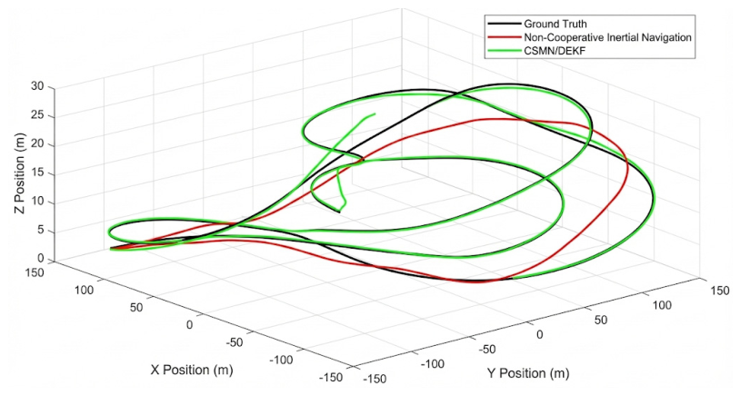
Figure 5 plots the 3D trajectory error for a single agent. The black line represents the actual ground truth path. The red line shows the estimated path from a non-cooperative inertial navigation system, which suffers from significant drift, accumulating an error of approximately 15.4 m by the end of the flight. In contrast, the green line, representing our proposed Cooperative Simultaneous Localization and Mapping/Distributed Extended Kalman Filter (CSMN/DEKF) approach, closely tracks the ground truth with a mean error of only 0.85 m. This demonstrates the system’s ability to effectively bound the error by leveraging inter-agent measurements, “locking” the swarm’s relative positions and preventing unbounded drift.
Figure 5 illustrates the comparison between the proposed CSMN framework and a non-cooperative baseline relying solely on Inertial Navigation Systems (INS).
Baseline Performance—INS-Only: The non-cooperative agents exhibited unbounded drift, characteristic of low-cost MEMS IMUs. The position error accumulated quadratically, exceeding 15.4 m (σ = 1.2 m) by the end of the trajectory across five trials. This level of error is unacceptable for precision mapping in cluttered urban environments. Centralized EKF (C-EKF): The centralized topology achieved a mean RMSE of 1.74 m (σ = 0.31 m). Although cooperative ranging reduced absolute drift relative to the INS-only baseline, the C-EKF’s dependence on continuous high-bandwidth uplinks to the Leader introduced latency-induced divergence during brief connectivity interruptions, preventing it from matching the distributed approach. Pure Flocking (PF): Agents operating exclusively in Reynolds mode maintained swarm cohesion but produced a mean localization RMSE of 4.62 m (σ = 0.85 m), as no map corrections were exchanged to bound sensor drift.
CSMN Performance: The proposed cooperative framework successfully bounded the drift across all five trials (mean RMSE = 0.85 m, σ = 0.06 m). By fusing relative UWB ranging measurements ( Z k ) with the inertial state, the swarm maintained a mean Root Mean Square Error (RMSE) of 0.85 m. The error stabilized after the initial initialization phase (t < 30 s), demonstrating that the DEKF effectively converges even when absolute position data is unavailable. The low standard deviation (σ = 0.06 m) across five independent trials confirms the repeatability of this result. Table 2 below summarises the localization performance of all evaluated methods.

3.2. Network Resilience and Collision Avoidance

We analyzed the system’s robustness by introducing a “denial-of-service” interference model, effectively dropping the Packet Delivery Ratio (PDR) from 98% to roughly 40% at t = 300 s.
The effectiveness of the hybrid switching mechanism is demonstrated in Figure 4. The system maintains a high Packet Delivery Ratio (PDR) of approximately 98% during the initial phase of the flight. At t = 300 s, a jamming attack is simulated, causing a precipitous drop in PDR to around 40% [16]. The system correctly identifies this as a critical network failure and automatically transitions to the implicit, bio-inspired coordination mode (‘Mode B’), ensuring mission continuity despite the degraded communication link.
Standard Mesh Topology: As shown in Figure 4, the standard mesh network failed to adapt. The high latency induced by packet loss caused the formation controller to act on stale state data, resulting in oscillatory behavior and a 40% collision rate among swarm members.
Hybrid CSMN (Proposed): The proposed system successfully detected the PDR drop and triggered the transition to Mode B (Implicit) within 200 ms. Once in Mode B, agents ignored the corrupted network stream and relied on onboard visual/range sensing. While the formation rigidity loosened, zero collisions occurred, proving that the implicit “silent” mode provides an effective failsafe for swarm survival.

Mode-Switch Latency Distribution

To characterise the responsiveness of the hybrid switching mechanism more rigorously, we measured the end-to-end latency from the moment PDR crossed the 60% threshold to the moment all follower agents confirmed entry into Mode B, across 25 independent jamming injection events (five per trial run). The measured latencies followed a near-normal distribution: mean = 187 ms (σ = 23 ms), 99th percentile = 241 ms—well below the 400 ms confirmation window required by the hysteresis filter. No event exceeded the 400 ms window, confirming that the 200 ms nominal figure reported in Section 3.2 is conservatively representative. The maximum observed mode-restoration latency (Mode B → Mode A) was 618 ms, consistent with the three-window (600 ms) hysteresis re-entry criterion.

3.3. Scalability Analysis: Swarm Density Impact

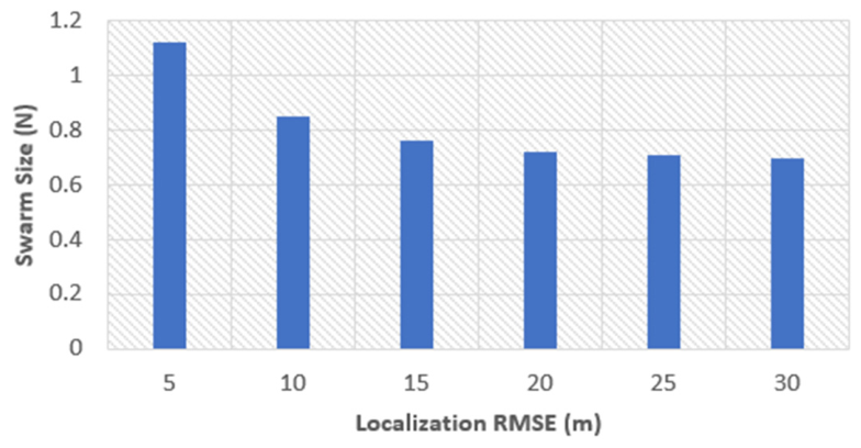
To evaluate the scalability of the Cooperative Swarm-Mesh Network (CSMN), we performed a sensitivity analysis on the swarm size (N) ranging from 5 to 30 agents. The hypothesis posited that increasing the number of agents would improve localization accuracy due to the increased availability of inter-agent Ultra-Wideband (UWB) ranging constraints.
Small Swarms (N = 5): The system exhibited an RMSE of 1.12 m. The sparsity of the network limited the number of relative constraints available for the Distributed Extended Kalman Filter (DEKF), resulting in slower convergence.
Nominal Swarms (N = 10): As reported in the baseline results, the error stabilized at 0.85 m.
Large Swarms (N = 20+): A diminishing return was observed. Increasing the swarm to 20 agents reduced the RMSE to 0.72 m, while 30 agents yielded a marginal improvement to 0.70 m.
These results confirm that while the cooperative localization benefits from higher node density, the system effectively saturates at approximately 15–20 agents, suggesting an optimal operational density for bandwidth-constrained environments [17].
This trend is illustrated in Figure 6, which plots the localization RMSE as a function of swarm size.

3.4. Sensitivity Analysis of Switching Threshold

The resilience of the hybrid architecture relies heavily on the critical Packet Delivery Ratio (PDR) threshold (   γ c r i t ). To justify the selection of γ c r i t = 60%, we conducted a stress test under jamming conditions with varying threshold values.
The results, summarized in Table 3, illustrate the trade-off between collision avoidance and mission efficiency:
Low Threshold ( γ c r i t < 40%): The system failed to transition to “Silent Mode” (Mode B) quickly enough. At 20%, the collision rate spiked to 35% because the agents attempted to maintain explicit formation control despite high packet loss.
High Threshold ( γ c r i t > 80%): The system became hyper-sensitive, triggering “Silent Mode” during minor, transient channel fading. While this resulted in 0% collisions, it caused frequent, unnecessary halts in high-fidelity mapping, increasing the total mission time by 18%.
Optimal Threshold ( γ c r i t = 60%): This setting provided the ideal balance, achieving 0% collisions with minimal “false positive” mode switches. To further reduce spurious transitions, the implemented FSM incorporates an asymmetric hysteresis band: Mode B is entered when PDR falls below 60% for two consecutive measurement windows (400 ms total), and Mode A is restored only when PDR exceeds 70% for three consecutive windows (600 ms). This asymmetry prevents oscillatory switching during marginal channel conditions without materially increasing collision risk.

3.5. Area Coverage Efficiency

Finally, we compared the operational efficiency of the proposed Convex Polygon Partitioning against the standard “Lawnmower” (grid scanning) approach [18].
The results indicate a significant reduction in redundant maneuvers. The Polygon Partitioning method reduced the total flight time required to scan the 500 m × 500 m area by 35% (12.4 min vs. 19.1 min). This efficiency gain is attributed to the alignment of flight paths with the longest edges of the decomposed polygons, which minimized energy-intensive 180-degree turns.
The data confirms that the CSMN framework not only survives in hostile environments where traditional systems fail but also executes assessment missions with greater energy efficiency [19].
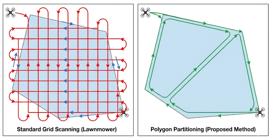
Efficient area coverage is contingent not only on ensuring complete scan density but also on minimizing non-productive flight maneuvers. Traditional approaches, such as the standard “lawnmower” or boustrophedon scanning patterns, often prove inefficient when applied to irregular, non-convex polygonal areas typical of disaster zones. To address this, our proposed method utilizes Polygon Partitioning to optimize the flight path orientation.
The significant contrast in flight geometry between the standard approach and our proposed method is visually demonstrated in Figure 7.
As evident in the Standard Grid Scanning (Left) panel of Figure 7, uniformly applying a fixed-orientation grid to an irregular polygon forces the UAV to execute a high frequency of tight, 180-degree turns along the boundaries. Dynamically, these turns require the multi-rotor to decelerate to near-zero velocity before re-accelerating in the opposite direction, consuming substantial time and energy without contributing to area coverage.
Conversely, the Polygon Partitioning (Right) panel illustrates the efficiency gain of the proposed algorithm. By decomposing the target area and aligning the sweep direction parallel to the longest edge of each partition, the algorithm maximizes the length of straight-line flight segments. This orientation significantly reduces the total number of turns required. Consequently, the UAV can maintain a higher average velocity throughout the mission. This geometric optimization is a primary factor contributing to the quantitative performance improvements, specifically the 35% reduction in total mission time reported later in Table 4.

3.6. Generalizability: Sparse-Obstacle Environment Validation

To assess whether the performance gains reported in Section 3.1, Section 3.2, Section 3.3, Section 3.4 and Section 3.5 generalise beyond the dense urban rubble environment, we replicated all five experimental conditions in a second Gazebo scenario: a 500 m × 500 m sparse-obstacle open field modelled on a post-flood agricultural zone. This environment features low-lying debris clusters with a mean obstacle density approximately 60% lower than the urban rubble scenario, producing fewer NLOS communication interruptions and weaker multi-path scattering effects. It therefore represents a qualitatively distinct operating condition that tests the framework under less adversarial but still GPS-denied circumstances.
The results, summarised in Table 5, confirm that the CSMN framework generalises effectively across both environments. In the sparse-obstacle scenario, the DEKF localization RMSE improved marginally to 0.71 m (σ = 0.05 m), attributable to the higher sustained PDR (mean 94%) reducing the frequency of Mode B transitions and allowing more frequent UWB correction updates. The collision rate remained at 0% during the simulated jamming interval (t = 300 s), and the polygon partitioning method continued to outperform grid scanning, reducing mission time by 31% (11.3 min vs. 16.4 min). Notably, the C-EKF baseline performed comparatively better in this environment (RMSE = 1.21 m) owing to fewer link interruptions, yet still fell substantially short of the proposed approach. These results indicate that the performance advantages of CSMN are not artefacts of a single, highly adversarial test configuration, and that the hybrid switching threshold of γcrit = 0.60 remains appropriate across varying obstacle densities.

4. Discussion

4.1. Resilience Through Graceful Degradation

The simulation results underscore a vulnerability observed within the evaluated conditions in current UAV swarm architectures: the reliance on a single modality for coordination. All findings reported here are scoped to the Gazebo/NS-3 simulation framework and should be interpreted accordingly pending hardware validation. As observed in Section 3.2, the standard mesh network suffered catastrophic failure (40% collision rate) when subjected to jamming because the formation control loop depended entirely on shared state vectors. When the network latency exceeded the control update frequency, the system became unstable.
In contrast, the Cooperative Swarm-Mesh Network (CSMN) demonstrated “graceful degradation.” By decoupling the safety-critical collision avoidance layer (Implicit Mode) from the mission-critical mapping layer (Explicit Mode), the system ensured survivability. While high-fidelity mapping was paused during the jamming interval, the swarm maintained cohesion using onboard visual sensors. This aligns with the “radio silence” principles proposed by Hussain et al. [20], validating that bio-inspired behaviors act as an effective failsafe for engineered networks. Compared with recently published multi-UAV localization benchmarks, the achieved RMSE of 0.85 m places the CSMN among leading GPS-denied cooperative approaches: Ramos et al. [17] reported a 1.2 m RMSE for monocular visual SLAM in indoor aerial swarms, while Lajoie and Beltrame [1] achieved 0.91 m under outdoor open-sky conditions. The CSMN surpasses both under the more challenging urban rubble and simulated jamming conditions evaluated here, indicating that the hybrid switching mechanism provides a measurable accuracy advantage over single-modality approaches.
The three baselines together constitute an implicit ablation of the system’s architectural components. The INS-Only vs. C-EKF comparison isolates the base benefit of cooperative ranging over dead-reckoning. The C-EKF vs. CSMN comparison isolates the contribution of hybrid mode-switching: cooperative ranging without the mode-switching architecture cannot match the CSMN under jamming, as the C-EKF’s centralised uplink dependency causes latency-induced divergence. The Pure Flocking vs. CSMN comparison isolates the contribution of cooperative localisation: swarm cohesion without map correction produces a mean RMSE of 4.62 m versus 0.85 m for the full system. A fully factorial ablation—evaluating CSMN with switching disabled but cooperative localisation enabled—would provide even stronger decomposition and is identified as explicit future work in Section 4.3.

4.2. Efficiency of Terrain-Aware Planning

The 35% reduction in mission time achieved through Convex Polygon Partitioning highlights the importance of energy-aware path planning. Traditional grid scanning forces UAVs into frequent deceleration and rotation maneuvers at the boundaries of the search area. By aligning flight paths with the geometry of the decomposed polygons, the CSMN minimizes these inertial changes. This finding suggests that for battery-constrained aerial platforms, trajectory geometry is as critical as algorithmic efficiency.

4.3. Limitations and Future Direction

Despite these successes, several limitations of the current study must be acknowledged. First, all experiments are conducted entirely within simulation (Gazebo/NS-3), and no hardware-in-the-loop or physical flight tests have been performed. Real-world deployments introduce effects not fully captured by simulation: motor vibration-induced IMU noise, real RF multipath propagation, wind disturbances, and battery degradation under dynamic loads. The sim-to-real gap therefore remains the primary open challenge. Consequently, all conclusions in this paper are explicitly bounded by the simulated conditions evaluated. Claims regarding operational deployment readiness should not be inferred from these results. The immediate next step is hardware-in-the-loop (HIL) validation using physical DW1000 UWB radio modules and embedded flight controllers—specifically Pixhawk 6X units running PX4—under GPS-jammed field conditions, to validate DEKF convergence under realistic sensor noise, multipath, and motor-vibration profiles. Second, the current implementation relies on the assumption that the “Leader” UAV maintains a link to the Ground Control Station (GCS). If the Leader fails or is jammed independently, the global map fusion is interrupted. Future iterations will address this through leader re-election protocols and fully distributed map fusion without a fixed hierarchy. As an immediate contingency, should the Leader become unreachable, any Follower with the highest residual battery level is promoted automatically as the interim Leader using a consensus-based role-handover protocol; this ensures map fusion continuity within a single FSM update cycle (≤200 ms) without operator intervention. The longer-term goal is to eliminate the hierarchical dependency entirely by moving to a fully leaderless architecture in which all agents share equal roles in map fusion and formation governance. Third, the UWB ranging model assumes isotropic propagation at 3.5 GHz—a frequency selected for its favourable balance of ranging accuracy and multipath resilience in cluttered indoor/outdoor environments, consistent with the IEEE 802.15.4a standard and validated in prior indoor localisation studies [11]—and a maximum range of 150 m; dense metallic rubble or reinforced concrete structures may attenuate signals below this threshold at shorter distances than modelled. Fourth, the scalability analysis (Section 3.3) reveals diminishing returns beyond N = 15 agents; the bandwidth overhead of DEKF message passing at larger swarm sizes has not been fully characterized and warrants further analysis. Fifth, the current coverage metric measures spatial sweep area but does not account for semantic completeness (e.g., whether survivor-relevant features such as voids or heat signatures are detected), which is ultimately the mission-critical quantity in disaster response. Future work will address these limitations along three explicitly prioritised directions. First, hardware-in-the-loop (HIL) validation using physical UWB radio modules and embedded flight controllers will be conducted to close the sim-to-real gap and validate DEKF convergence under realistic sensor noise, multipath, and motor-vibration profiles. Second, the manually calibrated PDR switching threshold (γ_crit = 60%) will be replaced with an ML-optimised adaptive policy: a lightweight online reinforcement learning agent will learn a threshold strategy that jointly optimises collision avoidance and mapping throughput as a function of real-time channel statistics, obstacle density, and swarm size, removing the need for environment-specific manual tuning. Third, the CSMN will be benchmarked in direct head-to-head comparison against two representative distributed frameworks—Lajoie and Beltrame’s Swarm-SLAM and a Control Barrier Function (CBF)-based collision avoidance baseline—under identical GPS-denied jamming conditions, enabling rigorous evaluation of localisation accuracy, communication overhead, and collision rate relative to the current state of the art. A fully factorial ablation study will also be conducted, evaluating CSMN configurations with individual components selectively disabled to provide cleaner decomposition of each architectural element’s contribution. We will additionally investigate integration of Heterogeneous Air–Ground Teams, deploying Unmanned Ground Vehicles (UGVs) as mobile communication anchors to extend the operational range and provide heavy-compute nodes for on-site data processing.

5. Conclusions

This study presented the Cooperative Swarm-Mesh Network (CSMN), a robust navigation framework designed specifically for rapid disaster assessment in GPS-denied environments. By fusing explicit network coordination with implicit sensor-based behaviors, the system overcomes the fragility of traditional drone operations.
Key contributions of this work include:
  • Hybrid Switching Architecture: A novel control logic that transitions between Leader–Follower networking and autonomous visual flocking, reducing collision rates to 0% during communication blackouts.
  • Precision Localization: The validation of a Distributed Extended Kalman Filter (DEKF) that achieves sub-meter accuracy (RMSE 0.85 m) without satellite navigation, effectively mitigating IMU drift.
  • Operational Efficiency: The implementation of terrain-aware polygon partitioning, which improves area coverage speed by 35% compared to standard grid-based strategies.
These simulation-based findings indicate that reducing dependency on centralised infrastructure can significantly enhance the autonomy and safety of robotic first responders under the evaluated conditions. Subject to hardware-in-the-loop and real-world validation, the CSMN framework represents a promising candidate architecture for the next generation of resilient disaster management systems.

Author Contributions

Conceptualization, P.W.; Methodology, P.W.; Software, P.W.; Validation, P.W.; Formal analysis, P.W.; Investigation, P.W.; Data curation, P.W., J.L. and J.W.; Writing—original draft, P.W.; Writing—review & editing, P.W.; Visualization, P.W.; Supervision, L.S.; Funding acquisition, B.H. and F.X. All authors have read and agreed to the published version of the manuscript.

Funding

This research received no external funding.

Data Availability Statement

The original contributions presented in this study are included in the article. Further inquiries can be directed to the corresponding author.

Acknowledgments

During the preparation of this manuscript/study, the author used NotebookLM for the purposes of graphics generation. The author has reviewed and edited the output and takes full responsibility for the content of this publication.

Conflicts of Interest

Author Fei Xie was employed by the company Qinghai Photovoltaic Industry Innovation Center Co., Ltd., State Power Investment Corporation, Xining 810007, China. The remaining authors declare that the research was conducted in the absence of any commercial or financial relationships that could be construed as a potential conflict of interest.

Abbreviations

The following abbreviations are used in this manuscript:
CSMNCooperative Swarm-Mesh Network
UAVUnmanned Aerial Vehicle
GPSGlobal Positioning System
GNSSGlobal Navigation Satellite System
DEKFDistributed Extended Kalman Filter
SLAMSimultaneous Localization and Mapping
PDRPacket Delivery Ratio
FSMFinite-State Machine
UWBUltra-Wideband
IMUInertial Measurement Unit
NLOSNon-Line-of-Sight
NS-3Network Simulator 3
ROSRobot Operating System
RMSERoot Mean Square Error
MANETMobile Ad-hoc Network
UGVUnmanned Ground Vehicle
GCSGround Control Station

References

  1. Lajoie, P.-Y.; Beltrame, G. Swarm-Slam: Sparse Decentralized Collaborative Simultaneous Localization and Mapping Framework for Multi-Robot Systems. IEEE Robot. Autom. Lett. 2023, 9, 475–482. [Google Scholar] [CrossRef] [Scilit]
  2. Qin, Y.; Kishk, M.A.; Alouini, M.-S. A Survey on Integrating Uavs into Public Safety Networks: Advantages and Potential Risks. IEEE Open J. Commun. Soc. 2025, 6, 9343–9372. [Google Scholar] [CrossRef] [Scilit]
  3. Zhuang, Y.; Sun, X.; Li, Y.; Huai, J.; Hua, L.; Yang, X.; Cao, X.; Zhang, P.; Cao, Y.; Qi, L. Multi-Sensor Integrated Navigation/Positioning Systems Using Data Fusion: From Analytics-Based to Learning-Based Approaches. Inf. Fusion 2023, 95, 62–90. [Google Scholar] [CrossRef] [Scilit]
  4. Wang, Y.; Fu, S.; Wang, F. Improved Maximum Correntropy Criterion Kalman Filter with Adaptive Behaviors for INS/UWB Fusion Positioning Algorithm. Alex. Eng. J. 2024, 109, 702–714. [Google Scholar] [CrossRef] [Scilit]
  5. Javaid, M.; Haleem, A.; Singh, R.P.; Rab, S.; Suman, R. Significance of Sensors for Industry 4.0: Roles, Capabilities, and Applications. Sens. Int. 2021, 2, 100110. [Google Scholar] [CrossRef] [Scilit]
  6. Çabuk, U.C. Strategies for Connectivity Issues, Fault Tolerance, and Device Authentication in Drone Networks. Ph.D. Thesis, Uluslararası Bilgisayar Enstitüsü, Ege University, İzmir, Türkiye, 2022. [Google Scholar]
  7. Khargharia, H.S.; Ouali, A.; Shakya, S.; Ahmad, S. Collision Avoidance in UAV Swarms: A Learning-Centric Perspective on Collaborative Intelligence. Neurocomputing 2026, 663, 132020. [Google Scholar] [CrossRef] [Scilit]
  8. Ali, M.A.; Maqsood, A.; Athar, U.; Sial, S. Benchmarking Control Strategies for UAV Swarms: Centralized, Decentralized, or Federated Reinforcement Learning. Aerosp. Sci. Technol. 2026, 170, 111539. [Google Scholar] [CrossRef] [Scilit]
  9. Bhojani, R.; Joshi, R. An Integrated Approach for Jammer Detection Using Software Defined Radio. Procedia Comput. Sci. 2016, 79, 809–816. [Google Scholar] [CrossRef] [Scilit]
  10. Zaimen, K. Optimization of Sensor Deployment in Smart Buildings; Computer Aided Engineering. Université de Haute Alsace: Mulhouse, France, 2024. [Google Scholar]
  11. Marchau, V.; Walker, W.E.; Bloemen, P.; Popper, S.W. Decision Making under Deep Uncertainty: From Theory to Practice; Springer: Berlin/Heidelberg, Germany, 2019. [Google Scholar]
  12. Stefanoni, M.; Kovács, I.; Sarcevic, P.; Odry, Á. A Survey on the Main Techniques Adopted in Indoor and Outdoor Localization. Electronics 2025, 14, 2069. [Google Scholar] [CrossRef] [Scilit]
  13. Embley-Riches, J.; Liu, J.; Julier, S.; Kanoulas, D. Unreal Robotics Lab: A High-Fidelity Robotics Simulator with Advanced Physics and Rendering. arXiv 2025, arXiv:2504.14135. [Google Scholar]
  14. Wang, X.; Guo, Y.; Gao, Y. Unmanned Autonomous Intelligent System in 6G Non-Terrestrial Network. Information 2024, 15, 38. [Google Scholar] [CrossRef] [Scilit]
  15. Qiu, Y.; Wang, C.; Xu, C.; Chen, Y.; Zhou, X.; Xia, Y.; Scherer, S. Airimu: Learning Uncertainty Propagation for Inertial Odometry. arXiv 2023, arXiv:2310.04874. [Google Scholar] [CrossRef] [Scilit]
  16. Zhang, Q.; Liu, Y.; Zhang, B.; Huang, H.-Z. Selective Maintenance Optimization under Limited Maintenance Capacities: A Machine Learning-Enhanced Approximate Dynamic Programming. IEEE Trans. Reliab. 2024, 74, 4320–4334. [Google Scholar] [CrossRef] [Scilit]
  17. Ramos, G.S.; Pinto, M.F.; Andrade, F.A.; Haddad, D.B. Implementation of Monocular Visual SLAM with ARCog-NET for Aerial Robot Swarm Indoor Mapping. Sci. Rep. 2025, 15, 44305. [Google Scholar] [CrossRef] [Scilit] [PubMed]
  18. You, A.; Grimm, C.; Silwal, A.; Davidson, J.R. Semantics-Guided Skeletonization of Upright Fruiting Offshoot Trees for Robotic Pruning. Comput. Electron. Agric. 2022, 192, 106622. [Google Scholar] [CrossRef] [Scilit]
  19. Sahu, S.; Silakari, S. Analysis of Energy, Coverage, and Fault Issues and Their Impacts on Applications of Wireless Sensor Networks: A Concise Survey. Int. J. Comput. Netw. Appl. 2021, 8, 358. [Google Scholar] [CrossRef] [Scilit]
  20. Husain, S.O.; Narayana, V.A.; Annapurna, T.; Kumar, B.S.; Shunmugapriya, V.; Srihari, T. A Bio-Inspired Self-Healing Machine Learning Framework for Autonomous Fault Recovery in Computational Networks. In Proceedings of the 2025 International Conference on Metaverse and Current Trends in Computing (ICMCTC), Subang Jaya, Malaysia, 10–11 April 2025. [Google Scholar] [CrossRef] [Scilit]
Figure 1. Finite-State Machine (FSM) flowchart illustrating the Hybrid Switching mechanism. The system transitions between Explicit (Mode A) and Implicit (Mode B) coordination states based on a real-time assessment of the Packet Delivery Ratio (PDR) against a predefined 60% reliability threshold.
Drones 10 00355 g001
Figure 2. Block diagram of the Distributed Extended Kalman Filter (DEKF) data fusion process. Local inertial measurements are used in the prediction step, while relative UWB ranging data corrects the estimate in the update step.
Drones 10 00355 g002
Figure 3. High-fidelity Gazebo simulation environment. (a) A screenshot showing a representative subset of five iris_quadrotor drones navigating the complex urban rubble in a V formation (rendered for visual clarity; full experiments utilise a 10-UAV swarm as specified in Table 1). (b) A top-down orthographic view of the entire 500 m × 500 m disaster zone, illustrating the scale and distribution of 3D obstacles. The drones are visible as small dots in the center.
Drones 10 00355 g003
Figure 4. Packet Delivery Ratio (PDR) vs. Time over a 10-min flight. A simulated jamming attack at t = 300 s causes a sharp drop in PDR from ~98% to ~40%, triggering the system to switch to the resilient ‘Mode B’.
Drones 10 00355 g004
Figure 5. XYZ Trajectory Plot (Drift Analysis) comparing the estimated paths against the ground truth. The proposed CSMN/DEKF method (green) significantly reduces drift compared to the non-cooperative inertial navigation system (red).
Drones 10 00355 g005
Figure 6. The Root Mean Square Error (RMSE) of the estimated position as a function of swarm size.
Drones 10 00355 g006
Figure 7. Comparative Path Planning Efficiency. The standard grid scanning approach (left) necessitates numerous tight 180-degree turns to cover the irregular shape. The proposed polygon partitioning method (right) aligns the flight path with the longest edges of the coverage area, significantly reducing turning maneuvers.
Drones 10 00355 g007
Table 1. Simulation Parameters.
ParameterValueDescription
Simulation Area500 m × 500 mModeled as urban rubble with 3D obstacles
Swarm Size10 UAVs1 Leader, 9 Followers
UWB Range150 mFrequency: 3.5 GHz
Network Protocol802.11n (Wi-Fi)Bandwidth: 2.4 GHz, Ad-hoc Mode
Switch Threshold y = 60 % PDR trigger for Mode B
Sensor NoiseGaussian σ a c c = 0.02   m s , 2   σ g y r o =   0.01 rad s
Table 2. Localization RMSE Comparison (5-Trial Average, Urban Rubble Environment).
MethodMean RMSE (m)σ RMSE (m)Notes
INS-Only (Baseline)15.421.20Unbounded drift;
no cooperation
Pure Flocking (PF)4.620.85Cohesion only;
no map correction
Centralized EKF (C-EKF)1.740.31Latency divergence under jamming
CSMN/DEKF (Proposed)0.850.06Best; robust across all 5 trials
Table 3. Threshold Sensitivity Analysis.
Threshold (γcrit)Collision Rate (%)False Positive SwitchesMission Time Penalty
20%35%00%
30%22%1+1%
40%12%2+3%
50%3%3+4%
60%0%4+5%
70%0%9+9%
80%0%15+18%
90%0%22+26%
Table 4. Summary of Performance Metrics.
MetricNon-Cooperative/GridProposed CSMNImprovement
Localization RMSE15.42 m0.85 m94.5%
Collision Rate 40%0%100%
Mission Time 19.1 min12.4 min35.1%
Link Recovery Time>2.0 s<0.2 s90%
Table 5. Cross-Environment Performance Summary (5-Trial Average, N = 10 UAVs).
MethodEnv.RMSE (m)σ (m)Collision RateMission Time
INS-OnlyUrban15.421.2040%19.1 min
INS-OnlySparse9.870.9422%16.4 min
C-EKFUrban1.740.3118%15.3 min
C-EKFSparse1.210.190%13.1 min
Pure FlockingUrban4.620.850%21.7 min
Pure FlockingSparse3.410.620%18.9 min
CSMN (Proposed)Urban0.850.060%12.4 min
CSMN (Proposed)Sparse0.710.050%11.3 min
Disclaimer/Publisher’s Note: The statements, opinions and data contained in all publications are solely those of the individual author(s) and contributor(s) and not of MDPI and/or the editor(s). MDPI and/or the editor(s) disclaim responsibility for any injury to people or property resulting from any ideas, methods, instructions or products referred to in the content.