1. Introduction
Smart grids have been subject of study with the objective of optimizing the energy production and distribution as well as the management of the end users service, in terms of security, remote operations diagnostics, etc. Furthermore, they allow the consumers to manage their consumption according to the available information since they can read their consumption and prices with more detail [
1]. Besides, it generates new business models for the energy providers such as the prepaid service [
1,
2,
3].
Nowadays, most gas meters in Spain are mechanical, which hinders the achievement of smart grids for the gas sector [
1]. The meters are periodically read by the user or an operator who takes a picture of the totalizer, which is prone to human mistakes and fraud billing [
4]. However, their substitution by electronic gas meters is generally not economically feasible. The alternative solution proposed here is to attach an electronic device to the already installed meter (jointly forming a smart gas meter). The smart meters benefit of the accuracy and the long term stability of the conventional gas meters and the advantages (traceability, security, reliability and easier management) of the electronic upgrade. This solution is carried out within the European project “EnSO” (Energy for Smart Objects) [
5].
2. Node Description
The add-on electronic device (node, hereafter) must have a long lifetime, small size and must be low cost [
4]. In addition, the main required functionalities of the smart meter are: store gas consumption information in fixed periods (days, weeks, etc.); identify and register alarms (low battery, tampering, detect strong magnetic fields, repeated attempts to establish a communication, etc.); and communicate with smartphones through NFC (the user and operator use a smartphone application to perform the management and reading of the smart meter).
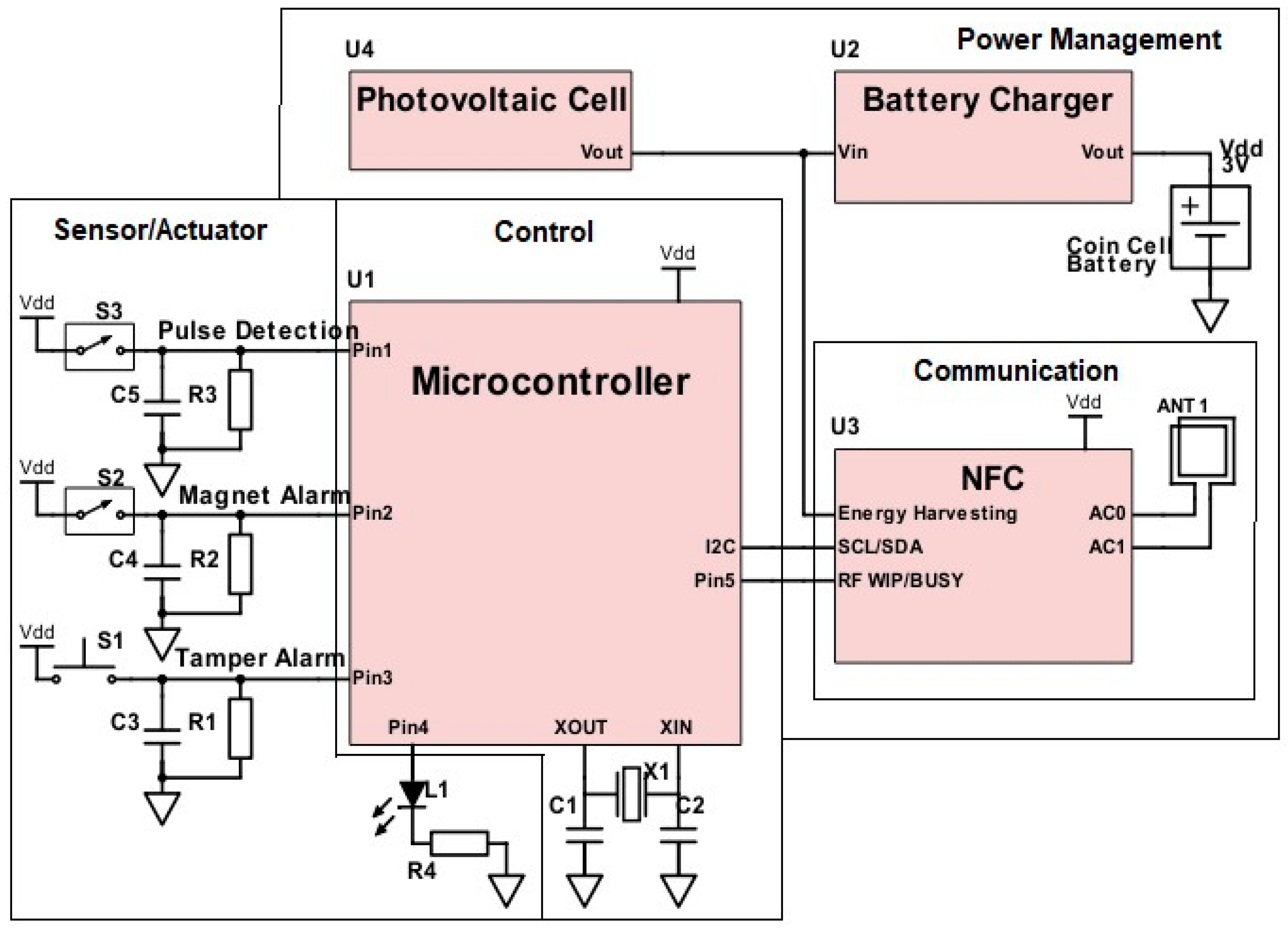
Figure 1 shows a detailed block diagram. It consists of four main modules: power management, sensor/actuator, control and communication.
The power management module is designed for powering the node from a primary battery, solar cells or the NFC link. For this first version prototype, only primary batteries are considered, in particular coin cells.
The sensor/actuator module consists of three sensors (gas measurement, magnetic field and tamper detection) and one LED for indication purposes. The sensors are on/off switches. The operating principle of the gas measuring is based on that as the gas flows a transmission gear and a mechanical coupling transfer the reciprocating motion to the mechanical index, which has attached a permanent magnet in the index drum that represents the less significant digit. A reed switch is positioned in the edge of the node and is activated whenever the magnet passes in front of it. The resolution of the mechanical measure is 0.001 m
3, whereas the digital measure is 0.01 m
3, which corresponds to a complete turn of the index drum.
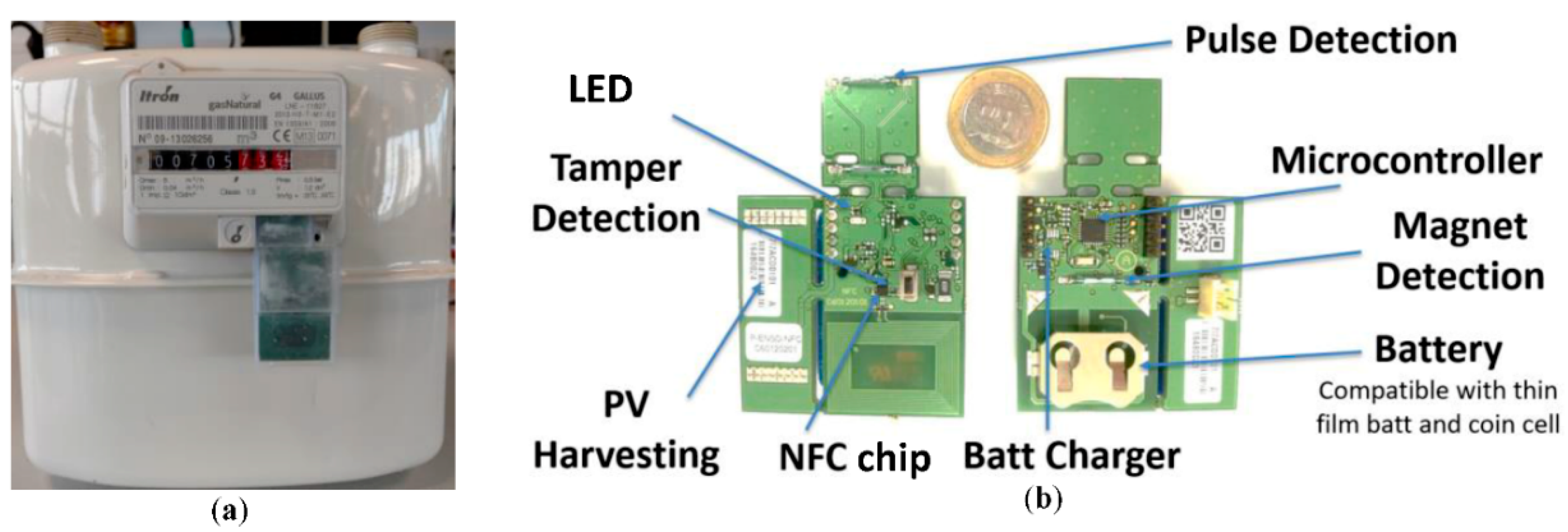
Figure 2a shows the node attached to a mechanical gas meter (Gallus 2000) [
6]. On the other hand, a reed switch activates an alarm when a strong magnetic field is attempting to corrupt the gas measurement. Finally, the tamper detection consists of a button that is pressed against the case of the electronic device. If someone breaks the plastic case, the switch will be unpressed, generating an alarm.
The control module includes a STM32L0 series microcontroller, which gathers, stores and processes the information of the sensors and the communication module.
The communication module consists of a NFC transceiver. A smartphone is used to interconnect the smart meters with an Internet of Things platform, which is developed by a third-party company. The smartphone uses an android application for installation, configuration, activation, management and maintenance actions.
Figure 2b presents the printed circuit board (PCB) of the electronic device with a description of its elements. The dimensions of the node are 70 mm × 30 mm (without the solar cell). The estimated unitary cost is from 5€ to 7€ depending on the production volume.
3. Performance/Experimental Results
Performed tests using an emulated gas flow on an ITRON counter (
Figure 2a) validated a correct performance of the gas reading process. The magnetic field detection was validated by bringing a magnet closer to the sensor. The tamper detection was tested by opening the plastic case of the electronic device. Besides, extensive tests were also performed for assessing the reading range and reliability of the NFC communication and the operating lifetime of the node.
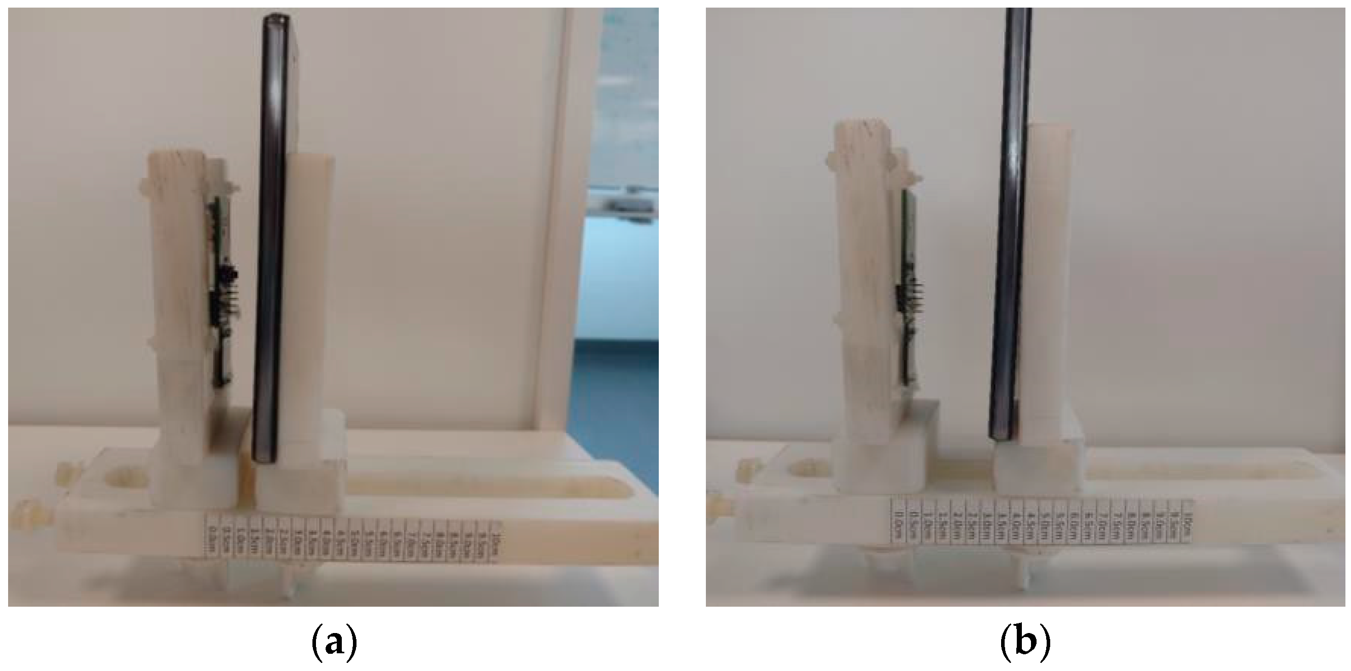
Regarding the tests of the NFC communication, in order to avoid magnetic interference, a plastic structure was used to hold both the smartphone and the node. The structure was placed on a clear laboratory table (
Figure 3). Two smartphones models were used: the Huawei P8 Lite ALE-L21 and the Motorola Moto X Style XT1572. Three versions of the node were tested to evaluate the influence of some metallic parts: (1) the original version (see
Figure 2b), (2) the node with the battery holder and all the copper removed from the back of the PCB coil and (3) and the node with the copper removed from the back of the PCB coil and with a ferrite plane between the PCB coil and the battery holder. Version 2 was powered externally.
Table 1 summarizes the maximum range achieved with the different setups measured with a resolution of 0.5 cm. As can be seen in
Figure 3a, the battery holder and the copper placed below the PCB coil limit the communication range (version 1). For the Huawei smartphone the range is constrained to 1 cm, whereas without the battery holder and the copper (version 2) a range of 3.5 cm is achieved for both smartphones (
Figure 3b). The magnetic field distribution of version 3 is similar to the one of version 2, therefore the same communication range is achieved. As the battery must be within the board, version 2 is not feasible. However, a practical solution for version 1 to increase the communication range is to move the battery holder to a different location. When this is not possible due to size restrictions, a ferrite plane can be added between the metal plane and the PCB coil (version 3) at the expense of a higher cost of the node (about 0.5€ to 0.7€ for high volume production).
For the estimation of the operating lifetime of the node, the current profile of the power supply was measured with an oscilloscope current probe (Labdevice). The internal shunt resistor was replaced by other values (1 Ω and 39 Ω) to obtain a better resolution of the measurements. The idle current was measured with a digital multimeter (34461A, Keysight).
Table 2 shows the estimated average current consumption for each task based on the assumption of their periodicity. With a 230 mAh coin cell battery, the lifetime of node is 600 days (about 20 months). This lifetime is insufficient for the application and a thorough analysis and redesign has to be done to extend it to more than four years.


