Article

Finite-Time Modified Function Projective Synchronization Between Different Fractional-Order Chaotic Systems Based on RBF Neural Network and Its Application to Image Encryption

School of Mathematics and Statistics, Xidian University, Xi’an 710126, China
*
Author to whom correspondence should be addressed.
Fractal Fract. 2025, 9(10), 659; https://doi.org/10.3390/fractalfract9100659
Submission received: 18 August 2025 / Revised: 4 October 2025 / Accepted: 10 October 2025 / Published: 13 October 2025
(This article belongs to the Special Issue Advances in Dynamics and Control of Fractional-Order Systems)

Abstract

This paper innovatively achieves finite-time modified function projection synchronization (MFPS) for different fractional-order chaotic systems. By leveraging the advantages of radial basis function (RBF) neural networks in nonlinear approximation, this paper proposes a novel fractional-order sliding-mode controller. It is designed to address the issues of system model uncertainty and external disturbances. Based on Lyapunov stability theory, it has been demonstrated that the error trajectory can converge to the equilibrium point along the sliding surface within a finite time. Subsequently, the finite-time MFPS of the fractional-order hyperchaotic Chen system and fractional-order chaotic entanglement system are realized under conditions of periodic and noise disturbances, respectively. The effects of the neural network parameters on the performance of the MFPS are then analyzed in depth. Finally, a color image encryption scheme is presented integrating the above MFPS method and exclusive-or operation, and its effectiveness and security are illustrated through numerical simulation and statistical analysis. In the future, we will further explore the application of fractional-order chaotic system MFPS in other fields, providing new theoretical support for interdisciplinary research.

1. Introduction

Fractional calculus is a generalization of ordinary differentiation and integration to arbitrary (non-integer) order, with its origins dating back to the 17th century. It pioneers a novel approach for understanding global linear differential and integral operators by integrating Newton-Leibniz concepts of integer-order derivatives with Cauchy’s formula for repeated integrals [1,2]. Compared to integer-order derivatives, fractional-order derivatives have global correlation and long-term memory, providing an excellent tool to better characterize phenomena with memory and genetic properties [3]. In recent decades, fractional calculus has emerged from pure mathematical science into widespread applications across engineering, finance, biomedicine, electrical circuits, and other fields [4,5,6,7]. Extensive research indicates that fractional calculus enhances the descriptive capability of corresponding models and reveals many dynamical phenomena that are difficult to observe within integer-order frameworks [8]. Among these, fractional-order chaotic systems have garnered significant attention in recent years due to their nonlocal memory properties, exhibiting more complex and richer dynamical behaviors than their integer-order counterparts [9].
On the other hand, due to the multiple values of chaotic synchronization in theoretical research and practical applications, it has received extensive attention from the academic and engineering communities since its inception [10]. So far, several types of synchronization have emerged, such as complete synchronization [11], generalized synchronization [12], anti-synchronization [13], phase synchronization [14] and projection synchronization [15,16]. In recent years, researchers introduced function projective synchronization (FPS) based on proportional scaling, which is unique in that it abandons the traditional synchronization with a constant scale factor and instead achieves synchronization based on a functional scaling relationship [17,18]. In 2009, Du et al. [19] further provided the definition of modified function projection synchronization (MFPS), and illustrated the MFPS phenomenon with an example of an integer-order Lorenz system. The MFPS implies that the drive and response systems can be synchronized according to an arbitrary given scaling function diagonal matrix, and the complexity and flexibility of the synchronization process are greatly improved [20,21], which makes it more difficult for chaotic signals to be intercepted or decrypted during transmission in the field of secure communication, thereby improving the security of information transmission. Therefore, MFPS displays significant research value and broad application prospects in fields such as image encryption and network security [22,23,24,25].
Over the past decade, with the refinement of fractional calculus theory and advancements in numerical simulation techniques, several meaningful results have been achieved on MFPS for fractional-order chaotic systems. Zhou et al. [26] introduced an adaptive MFPS scheme between entirely different fractional-order chaotic systems with uncertain parameters. Geng et al. [27] designed a controller based on the stability theory and tracking control of fractional-order systems to realize MFPS between integer-order and random fractional-order nonlinear systems. Ouannas et al. [28] presented an MFPS scheme for non-identical systems with different dimensionality and order characteristics. Du [29] proposed a robust adaptive control method to realize MFPS between two fractional-order complex dynamical networks. Dessoky et al. [30] analyzed combined MFPS of different fractional-order chaotic dynamical systems through numerical simulation. He et al. [31] addressed an adaptive MFPS for multi-time delayed fractional order memristor-based neural networks with parameter uncertainty.
However, the above mentioned MFPS control on fractional-order chaotic systems mainly focuses on asymptotic synchronization, whereas it is particularly important to achieve MFPS in finite-time in practical applications, especially in critical fields emphasizing efficient and real-time performance. The concept of finite-time control originated from the notion of short-time stability first proposed by Dorato in 1961 [32]. Subsequently, Bhat et al. [33] put forward the judgment basis of finite-time stability theory. Finite-time control refers to how the system can quickly converge to the equilibrium point in a finite-time interval, and its significant advantage lies in the fast convergence speed and strong anti-interference ability. Currently, researchers have successfully achieved finite-time synchronization of fractional-order chaotic systems using various control methods such as adaptive control [34], fuzzy control [35] and sliding mode control [36]. Among them, the sliding mode control method has attracted considerable attention due to its unique advantages, such as favorable transient performance and rapid dynamic response. Delavari et al. [37] put forward a novel adaptive sliding mode control method to synchronize non-identical fractional-order chaotic and hyper-chaotic systems in a finite time. Taheri et al. [38] designed a dynamic-free sliding mode controller to attain complete synchronization for a class of unknown fractional-order laser chaotic systems with input saturation. Huang et al. [39] proposed a finite-time adaptive synchronization method for the projection synchronization of fractional-order memristor chaotic systems with unknown parameters. Wu et al. [40] investigated inter-layer projective synchronization of fractional-order two-layer networks based on the sliding mode control technique.
It is worth noting that there are studies combining sliding mode control with radial basis function (RBF) neural networks to successfully achieve complete synchronization of fractional-order chaotic systems. The RBF neural network has the advantages of strong global approximation ability, simple structure and fast learning speed, which can effectively approximate the model uncertainty and external perturbation. Liu et al. [41] presented an adaptive fractional sliding mode controller based on RBF neural networks to improve the performance of a three-phase shunt active power filter. Yousefpour et al. [42] designed an adaptive terminal sliding mode controller with the RBF neural network for a new class of fractional-order hyper chaotic economic systems to achieve finite-time complete synchronization. Nian et al. [43] achieved module-phase synchronization of two fractional-order complex chaotic systems combined with RBF neural network and sliding mode control. Yang et al. [44] developed an innovative predefined-time sliding mode control approach incorporating an RBF neural network to attain fast synchronization of fractional-order financial systems. However, to the best of our knowledge, existing literature has not yet addressed the research of MFPS for fractional-order chaotic systems within a finite time. Therefore, inspired by the aforementioned discussions, this paper tries to explore sliding mode control method based on the RBF neural network, aiming to realize finite-time MFPS for different fractional-order chaotic systems containing uncertainties and external disturbances.
The organization of this paper is as follows: Section 2 provides the definitions, lemmas and necessary statements required for the proof of this paper. A finite-time MFPS scheme combining RBF neural networks and sliding mode control is illustrated in Section 3. In Section 4, the effectiveness of the presented finite-time MFPS scheme is illustrated by numerical simulations and the effect of the neural network parameters on the MFPS performance is analyzed. The above finite-time MFPS scheme is applied to image encryption and statistical analyses are performed in Section 5. Finally, concluding remarks are included in Section 6.

2. Some Preliminaries

2.1. Fractional Calculus

There are some frequently used definitions of fractional derivatives, such as the Grünwald-Letnikov definition, the Riemann-Liouville definition, and the Caputo definition. In particular, the initial values of the Caputo fractional-order derivative take the same form as the initial values of the integer-order derivative, which have a widely known understood physical meaning. Motivated by the above advantage, the Caputo definition is adopted for this paper.
Definition 1
([45]). The Caputo fractional derivative of order q for the function f ( t ) is defined as follows
D t q 0 C f ( t ) = 1 Γ ( n q ) 0 t ( t τ ) n q 1 f ( n ) ( τ ) d τ ,   n 1 < q n ,
where Γ ( · ) is the Gamma function. To facilitate the writing, D q is used instead of D t q 0 C in the following.
Lemma 1
([45]). Suppose f ( t ) R is a continuous and derivable function, then for any time instant t 0 , the following inequality holds
1 2 D q f 2 ( t ) f ( t ) D q f ( t ) , q ( 0 , 1 ) .
Lemma 2
([46]). Let x = 0 be an equilibrium point for the nonlinear fractional-order system D q x ( t ) = f ( x , t ) , q ( 0 , 1 ) . Assume that there exists a Lyapunov function V ( t , x ( t ) ) and class-𝒦 functions υ i ( i = 1 , 2 , 3 ) satisfying
υ 1 x ( t ) V ( t , x ( t ) ) υ 2 x ( t ) , D q V ( x , t ) υ 3 x ( t ) .
Then, the equilibrium point x = 0 is asymptotically stable.
Lemma 3
([47]). For q ( 0 , 1 ) and μ R , if f ( t ) is a continuous function, then
D q f μ ( t ) = T ( 1 + μ ) T ( 1 + μ q ) f μ q ( t ) D q f ( t ) .

2.2. Modified Function Projective Synchronization (MFPS)

Definition 2
([19]). Consider the drive system D q x = f ( x ) , x R n and the controlled response system D q y = h ( y , u ( x , y ) ) , y R n where q ( 0 ,   1 ) . The drive and response systems are said to achieve MFPS with respect to the scaling function matrix Z ( t ) = d i a g ( z 1 ( t ) , z 2 ( t ) ,   ,   z n ( t ) ) , if there exists a controller u ( x , y ) R n satisfying lim t Z ( t ) x y = 0 , where z i ( t ) 0 ( i = 1 ,   2 ,   ,   n ) are continuously differentiable bounded functions. If z 1 ( t ) = z 2 ( t ) = = z n ( t ) , the modified function projection synchronization (MFPS) is simplified to the function projective synchronization (FPS).

2.3. RBF Neural Networks Estimator

In the field of control engineering, RBF neural networks play an irreplaceable important role in approximating unknown nonlinear functions with any precision. Compared to traditional multilayer neural networks, RBF neural networks not only have a simple and clear structure, but also have excellent performance in convergence speed [42].
In this paper, the RBF neural network is employed to approximate the model uncertainties and external disturbances δ i ( Y , t ) , which can be described as
δ i ( Y , t ) = j = 1 m w i j φ j ( Y ) + ε δ i = W i T Φ ( Y ) + ε δ i , i = 1 ,   2 ,   ,   n ,
where Y = ( y 1 , y 2 ,   ,   y n ) T is the input of the neural network, Φ = ( φ 1 , φ 2 , , φ m ) T denotes the basis function of hidden nodes, W i = ( w i 1 ,   w i 2 ,   ,   w i m ) T represents the ideal weight of the network, and ε δ i indicates the approximation error of the network.
Here, the Gaussian function is selected as the basis function of hidden nodes, represented as
φ j ( Y ) = exp Y c j 2 2 b j 2 , j = 1 , 2 , , m ,
where c j and b j respectively denote the center vector and width of the Gaussian basis function, and m is the number of hidden nodes. Then, the output of the RBF neural network estimator is given by
δ ^ i ( Y , t ) = W ^ i T Φ ( Y ) ,
where W ^ i indicates the estimation of W i and the error of the weight estimation is defined as W ˜ i = W i W ^ i . To sum up, the structure of RBF neural network is illustrated in Figure 1, which includes the input layer, the hidden layer and the output layer.

3. Finite-Time MFPS Controller Design

In this section, we will propose a novel approach combining terminal sliding mode control with RBF neural networks to achieve finite-time MFPS for two completely different fractional-order chaotic (hyperchaotic) systems with model uncertainties and external disturbances.

3.1. Problem Description

Consider the nonlinear fractional-order drive system described by
D q 1 X ( t ) = f ( X , t ) + Δ f ( X , t ) + d f ( t ) ,
where q 1 ( 0 , 1 ) is the differential order and X = ( x 1 , x 2 , , x n ) T is the state vector. Δ f ( X , t ) = Δ f 1 ( X , t ) , Δ f 2 ( X , t ) , , Δ f n ( X , t ) T and d f ( t ) = d 1 f ( t ) , d 2 f ( t ) , , d n f ( t ) T are model uncertainties and external disturbances, respectively.
The response system adopts a completely different fractional-order chaotic system, which takes the following form
D q 2 Y ( t ) = h ( Y , t ) + Δ h ( Y , t ) + d h ( t ) + U ( t ) ,
where q 2 ( 0 , 1 ) is the differential order and Y = ( y 1 , y 2 , , y n ) T is the state vector. Δ h ( X , t ) = Δ h 1 ( X , t ) , Δ h 2 ( X , t ) , , Δ h n ( X , t ) T and d h ( t ) = d 1 h ( t ) , d 2 h ( t ) , , d n h ( t ) T define model uncertainties and external disturbances, respectively. U ( t ) = ( u 1 , u 2 , , u n ) is the control input to be determined.
The synchronization error between drive system (4) and response system (5) is defined as ε ( t ) = Z ( t ) X Y , where Z ( t ) = d i a g ( z 1 ( t ) , z 2 ( t ) , , z n ( t ) ) is the scaling function matrix. Then, the error dynamics can be described as
D q 2 ε ( t ) = D q 2 ( Z ( t ) X ) h ( Y , t ) Δ h ( Y , t ) d h ( t ) U ( t ) .
Its equivalent form is
D q 2 ε i ( t ) = D q 2 ( z i ( t ) x i ) h i ( y , t ) δ i ( y , t ) u i ( t ) ,
where δ i ( y , t ) = Δ h i ( y , t ) + d i h ( t ) , i = 1 , 2 , , n .

3.2. Fractional Terminal Sliding Surface

The new fractional-order nonsingular terminal sliding surface is defined as
s i = ε i + D q 2 σ i ε i + σ i s i g n ( ε i ) z i ε i φ 1 , i = 1 , 2 , , n ,
where σ i > 0 and 0 < φ 1 < 1 . When the fractional-order system operates in the sliding mode, it fulfills s i = 0 and D q 2 s i = 0 . Calculating the fractional-order derivative of the sliding mode surface (7) yields
D q 2 ε i ( t ) = σ i ε i σ i s i g n ( ε i ) z i ε i φ 1 , i = 1 , 2 , , n .
Theorem 1.
The state trajectory of the error system will converge to zero in finite time t s after reaching the sliding surface (7) and
t s t r + q 2 V 1 q 2 1 ( t r ) 2 η 1 q 2 , η = min 1 i n σ i ,
Proof of Theorem 1.
Let the Lyapunov function be V 1 = 1 2 i = 1 n ε i 2 . Based on Lemma 1, the following result can be obtained:
D q 2 V 1 i = 1 n ε i D q 2 ε i = i = 1 n ε i σ i ε i σ i s i g n ( ε i ) z i ε i φ 1 = i = 1 n σ i ε i 2 + σ i z i φ 1 ε i φ 1 + 1 i = 1 n σ i ε i 2 2 η V 1 ,
where η = min 1 i n σ i . According to Lemma 2, the state trajectories of the error system (6) tend to stabilize after reaching the sliding surface (7).
On the other hand, it follows from Lemma 3 that D q 2 V 1 q 2 1 2 η   Γ ( q 2 ) , and integrating from t r to on both sides of the inequality yields
V 1 q 2 1 ( t s ) V 1 q 2 1 ( t r ) 2 η   Γ ( q 2 ) ( t s t r ) q 2 T ( q 2 + 1 ) = 2 η ( t s t r ) q 2 q 2 .
Since V 1 ( t s ) = 1 2 i = 1 n ε i 2 ( t s ) = 0 , then one has t s t r + q 2 V 1 q 2 1 ( t r ) 2 η 1 q 2 . Therefore, the state trajectories of the error system (6) will converge to zero in a finite time t s .

3.3. Terminal Sliding Mode Control with RBF Neural Network

In order to force the state trajectories of the error system (6) to arrive at the sliding surface in a finite time and remain there forever, the finite-time sliding mode controller is designed as
u i ( t ) = D q 2 ( z i ( t ) x i ) h i ( y , t ) + σ i ε i + σ i s i g n ( ε i ) z i ε i φ 1 + κ i s i g n ( s i ) + τ i s i + γ i s i g n ( s i ) z i ε i φ 2 δ ^ i ( y , t ) , i = 1 , 2 , , n ,
where κ i > ε δ i ,   τ i > 0 ,   0 < φ 2 < 1 and δ ^ i ( y , t ) is the estimator of δ i ( y , t ) . Meanwhile, the adaptive law of weight estimation W ^ i is given by
D q 2 W ^ i = ρ i s i Φ ,
where ρ i > 0 and Φ ( ) indicate the basis function of hidden nodes.
Theorem 2.
The state trajectories of the error system (6) can converge to the sliding surface with the controller (9) and the adaptive law (10).
Proof of Theorem 2.
Taking the q 2 order derivative on both sides of Equation (7), one can derive that
D q 2 s i = D q 2 ε i + σ i ε i + σ i s i g n ( ε i ) z i ε i φ 1 .
Let the Lyapunov function be V 2 = 1 2 i = 1 n ε i 2 + 1 2 i = 1 n 1 ρ i W ˜ i T W ˜ i . According to Lemma 1, it can be concluded that
D q 2 V 2 = 1 2 i = 1 n D q 2 s i 2 + 1 2 i = 1 n D q 2 1 ρ i W ˜ i T W ˜ i i = 1 n s i D q 2 s i + 1 ρ i W ˜ i D q 2 W ˜ .
Substituting Equations (6), (9) and (11) into Equation (12), one has
D q 2 V 2 i = 1 n s i D q 2 ( z i ( t ) x i ) h i ( y , t ) δ i ( y , t ) u i ( t ) + σ i ε i + σ i s i g n ( ε i ) z i ε i φ 1 + 1 ρ i W ˜ i D q 2 W ˜ = i = 1 n s i δ i ( y , t ) κ i sign ( s i ) τ i s i γ i sign ( s i ) z i s i φ 2 + δ ^ i ( Y , t ) 1 ρ i W ˜ i D q 2 W ^ .
Thus, from Equations (1), (3) and (10), one can obtain
D q 2 V 2 i = 1 n s i W i T Φ ε δ i κ i sign ( s i ) τ i s i γ i sign ( s i ) z i s i φ 2 + W ^ i T Φ + 1 ρ i W ˜ i ρ i s i Φ = i = 1 n s i W ˜ i Φ ε δ i κ i sign ( s i ) τ i s i γ i sign ( s i ) z i s i φ 2 + s i W ˜ i Φ = i = 1 n s i ε δ i κ i sign ( s i ) τ i s i γ i sign ( s i ) z i s i φ 2 .
Considering κ i > ε δ i , it can be deduced that
D q 2 V 2 i = 1 n τ i s i 2 γ i z i φ 2 s i φ 2 + 1 .
Based on Lemma 2, the error system can converge to the sliding mode surface (7). □
Theorem 3.
The state trajectories of the error system (6) convergence to the sliding surface in finite time t r with the controller (9) and the adaptive law (10), where
t r q 2 V 3 q 2 1 ( 0 ) 2 ξ 1 q 2 ,   ξ = min 1 i n { τ i ψ i } .
Proof of Theorem 3.
Let the Lyapunov function be V 1 = 1 2 i = 1 n s i 2 . Based on Lemma 1, one can obtain
D q 2 V 3 i = 1 n s i D q 2 s i = i = 1 n s i D q 2 ( z i ( t ) x i ) h i ( y , t ) δ i ( y , t ) u i ( t ) + σ i ε i + σ i sign ( ε i ) z i ε i φ 1 = i = 1 n s i δ i ( y , t ) κ i sign ( s i ) τ i s i γ i sign ( s i ) z i s i φ 2 + δ ^ i ( y , t ) .
Then, employing Equations (1) and (3), we can arrive at
D q 2 V 3 i = 1 n s i W i T Φ ε δ i κ i sign ( s i ) τ i s i γ i sign ( s i ) z i s i φ 2 + W ^ i T Φ = i = 1 n s i W ˜ i Φ ε δ i κ i sign ( s i ) τ i s i γ i sign ( s i ) z i s i φ 2 i = 1 n s i W ˜ i Φ τ i s i 2 γ i z i φ 2 s i φ 2 + 1 i = 1 n s i W ˜ i Φ + τ i s i 2 .
From the definition of the basis function, it is known that Φ is bounded. On the other hand, the signal s i is bounded based on Theorem 2, thus W ˜ i is bounded. Consequently, we can always find a positive parameter ψ i which fulfills W ˜ i Φ ψ i s i . In conclusion, one has the following result
D q 2 V 3 i = 1 n ψ i s i 2 τ i s i 2 = i = 1 n τ i ψ i s i 2 .
Let τ i > ψ i and ξ = min 1 i n { τ i ψ i } , Equation (13) can be rewritten as
D q 2 V 3 i = 1 n ξ s i 2 = 2 ξ V 3 .
It is not difficult to obtain D q 2 V 3 q 2 1 2 ξ   Γ ( q 2 ) based on Lemma 3, and integrating from 0 to t r on both sides of the inequality yields
V 3 q 2 1 ( t r ) V 3 q 2 1 ( 0 ) 2 ξ   Γ ( q 2 ) t r q 2 T ( q 2 + 1 ) = 2 ξ t r q 2 q 2 .
Since V 3 ( t r ) = 1 2 i = 1 n s i 2 ( t r ) = 0 , then t r q 2 V 3 q 2 1 ( 0 ) 2 ξ 1 q 2 .
Therefore, the error system (6) converges to the sliding surface in finite time t r . Combining Theorem 1 and Theorem 3, it can be concluded the response system (5) and the drive system (4) can achieve MFPS in finite time ( t s + t r ) with the controller (9). □

4. Simulation Results

In this section, the MFPS between 4D fractional-order hyperchaotic Chen system [48] and 4D fractional-order chaotic entanglement system [49] is used to demonstrate the effectiveness of the proposed finite-time MFPS control scheme. Among them, the short-term predictor-corrector approach proposed in reference [50] is used to solve fractional-order differential equations.
The 4D fractional-order hyperchaotic Chen system with uncertainty and external disturbance is considered as the drive system
D q 1 x 1 = 35 ( x 2 x 1 ) + x 4 + Δ f 1 ( X , t ) + d 1 f ( t ) , D q 1 x 2 = 7 x 1 x 1 x 3 + 12 x 2 + Δ f 2 ( X , t ) + d 2 f ( t ) , D q 1 x 3 = x 1 x 2 3 x 3 + Δ f 3 ( X , t ) + d 3 f ( t ) , D q 1 x 4 = x 2 x 3 + 0.5 x 4 + Δ f 4 ( X , t ) + d 4 f ( t ) .
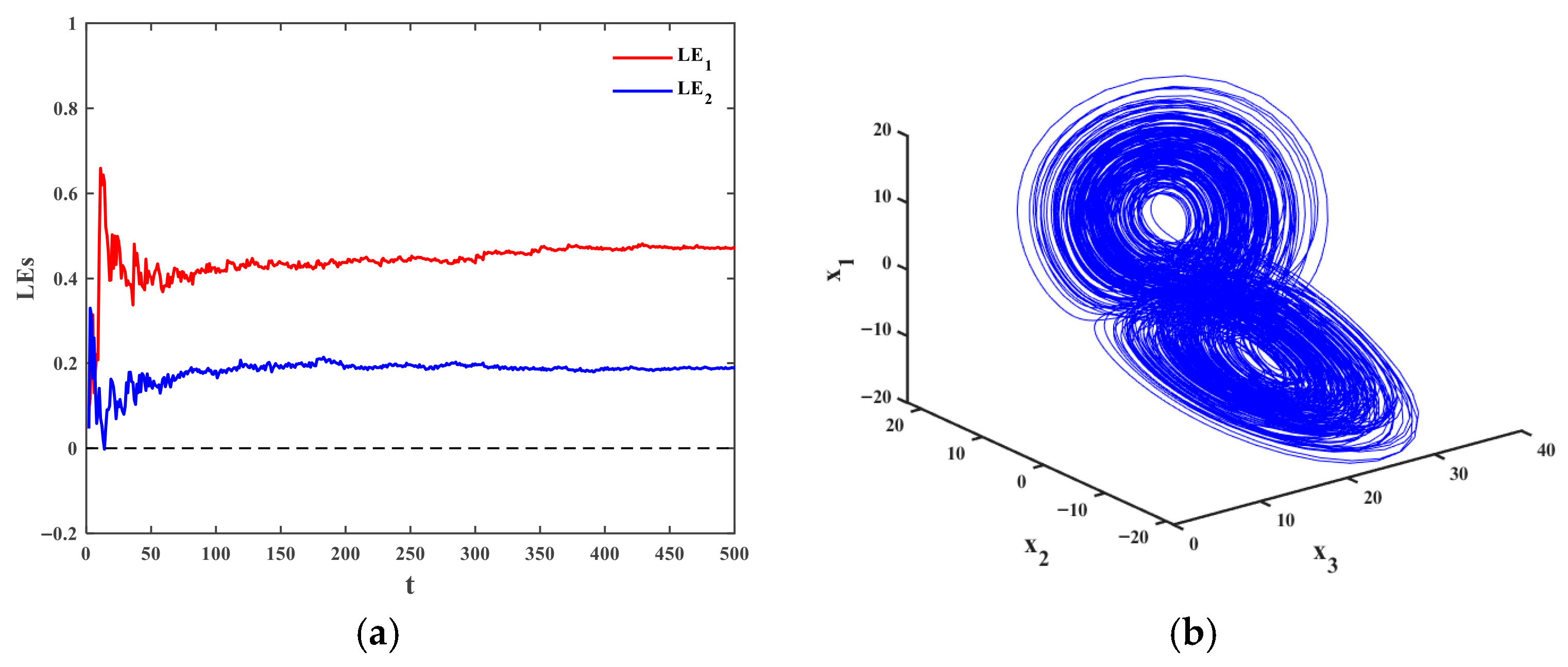
When Δ f i ( X , t ) d i f ( t ) 0 , system (14) can exhibit hyperchaotic behavior, as show in Figure 2, where q 1 = 0.98 and the initial condition is X ( 0 ) = ( 1 , 2 , 1 , 3 ) . Meanwhile, considering the 4D fractional-order chaotic entanglement system with uncertainty and external disturbance as the response system
D q 2 y 1 = y 1 + y 2 + 10 sin y 4 + Δ h 1 ( Y , t ) + d 1 h ( t ) + u 1 ( t ) , D q 2 y 2 = y 1 y 2 + 26 sin y 3 + Δ h 2 ( Y , t ) + d 2 h ( t ) + u 2 ( t ) , D q 2 y 3 = y 3 sin y 1 + Δ h 3 ( Y , t ) + d 3 h ( t ) + u 3 ( t ) , D q 2 y 4 = y 4 + sin y 2 + Δ h 4 ( Y , t ) + d 4 h ( t ) + u 4 ( t ) .
When Δ h i ( Y , t ) d i h ( t ) 0 , system (15) can display chaotic behavior, as show in Figure 3, where q 2 = 0.88 and the initial condition is Y ( 0 ) = ( 4 , 2 , 3 , 1 ) .
Then, the uncertainties in drive system (14) and response system (15) are given by
Δ f 1 = 0.2 sin ( 2 π t ) x 1 , Δ f 2 = 0.1 cos ( 3 π t ) x 2 , Δ f 3 = 0.3 sin ( 6 π t ) x 3 , Δ f 4 = 0.25 cos ( 4 π t ) x 4 , Δ h 1 = 0.15 cos ( 5 π t ) y 1 ,   Δ h 2 = 0.5 sin ( π t ) y 2 , Δ h 3 = 0.4 cos ( 2 π t ) y 3 , Δ h 4 = 0.2 sin ( 3 π t ) y 4 .
The scaling function factors are taken as
z 1 = 3 0.2 sign ( sin ( 0.3 π t ) ) , z 2 = 1.5 0.1 tanh ( cos ( 0.7 π t ) ) , z 3 = 0.7 + 0.01 cos ( 0.4 π t ) , z 4 = 0.5 + 0.7 sin ( 0.6 π t ) .
In addition, the parameters of the controller with RBF neural network estimator are specified as φ 1 = 0.6 , φ 2 = 0.1 , σ i = 15 , κ i = 5 , τ i = 20 , γ i = 5 , ρ i = 10 ( i = 1 , 2 , , 4 ) , and the initial condition of the RBF neural network weight is considered as a seven-dimensional zero matrix. Here, the two parameters of the Gauss basis function are determined in two steps. First, the K-Means clustering algorithm is used to obtain the center point of the basis function as C = [ 1 , 1 , 1 , 1 , 1 , 1 , 1 ] . Subsequently, the width of the basis function is determined as B = 1 based on the average distance between the center points. Finally, the output layer weights are obtained using the least squares method, respectively.

4.1. The Drive and the Response Systems with Periodic Disturbances

In this case, the external disturbances of the drive system (14) and response system (15) are periodic disturbances, which are denoted as
d 1 f ( t ) = 0.15 cos ( 5 t ) , d 2 f ( t ) = 0.5 sin ( t ) , d 3 f ( t ) = 0.1 sin ( 3 t ) , d 4 f ( t ) = 0.2 cos ( 2 t ) , d 1 h ( t ) = 0.1 cos ( 3 t ) , d 2 h ( t ) = 0.2 cos ( 4 t ) , d 3 h ( t ) = 0.25 sin ( 6 t ) , d 4 h ( t ) = 0.35 sin ( t ) .
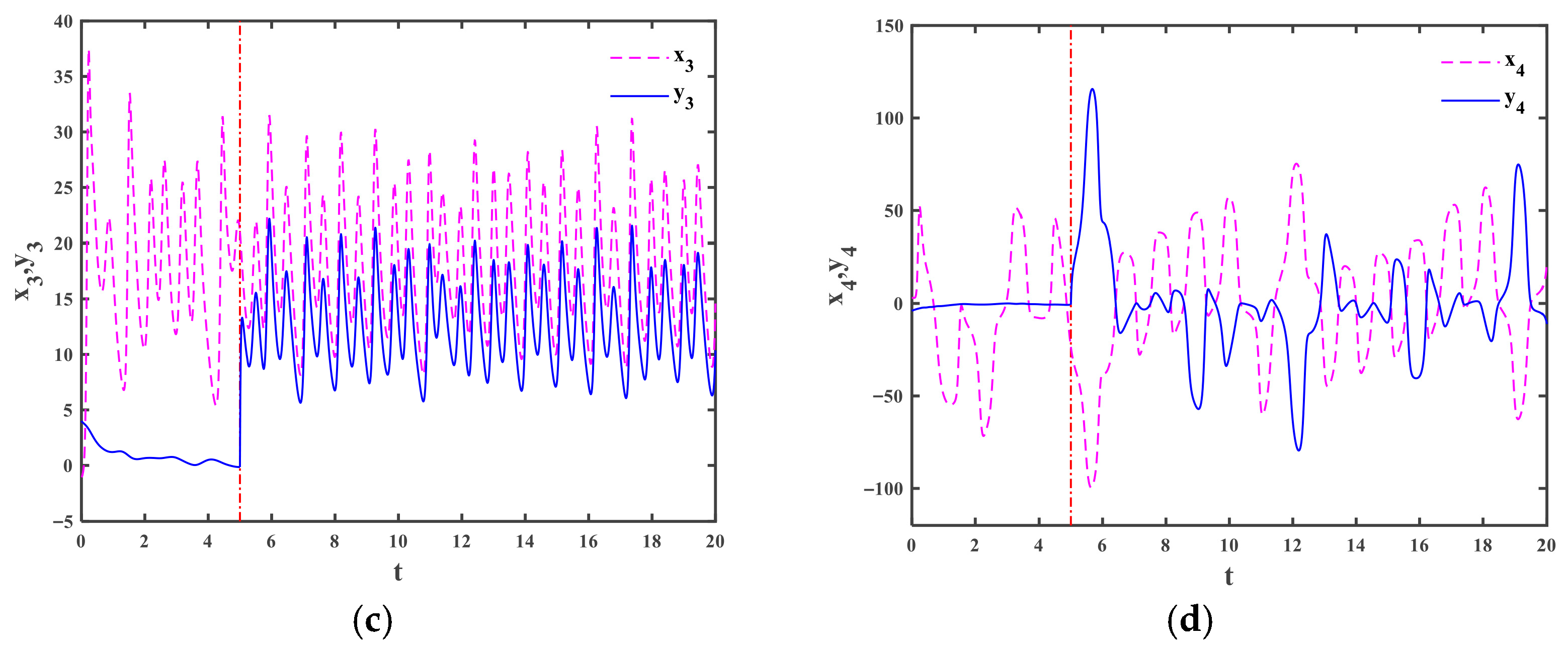
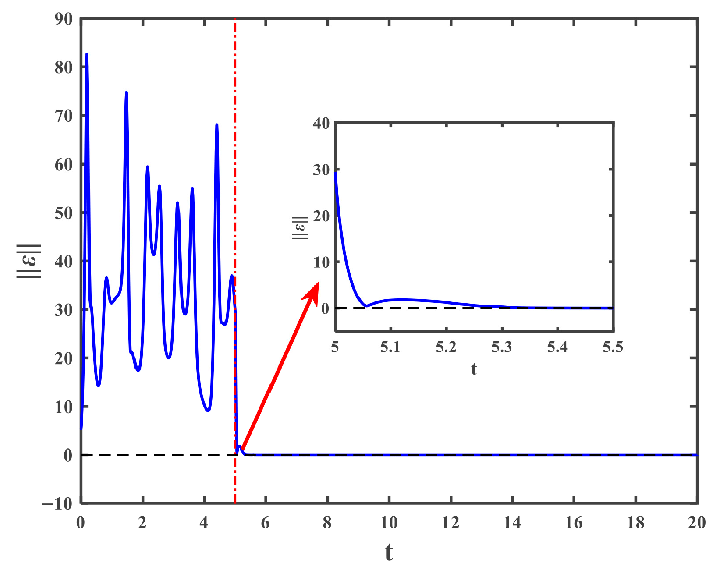
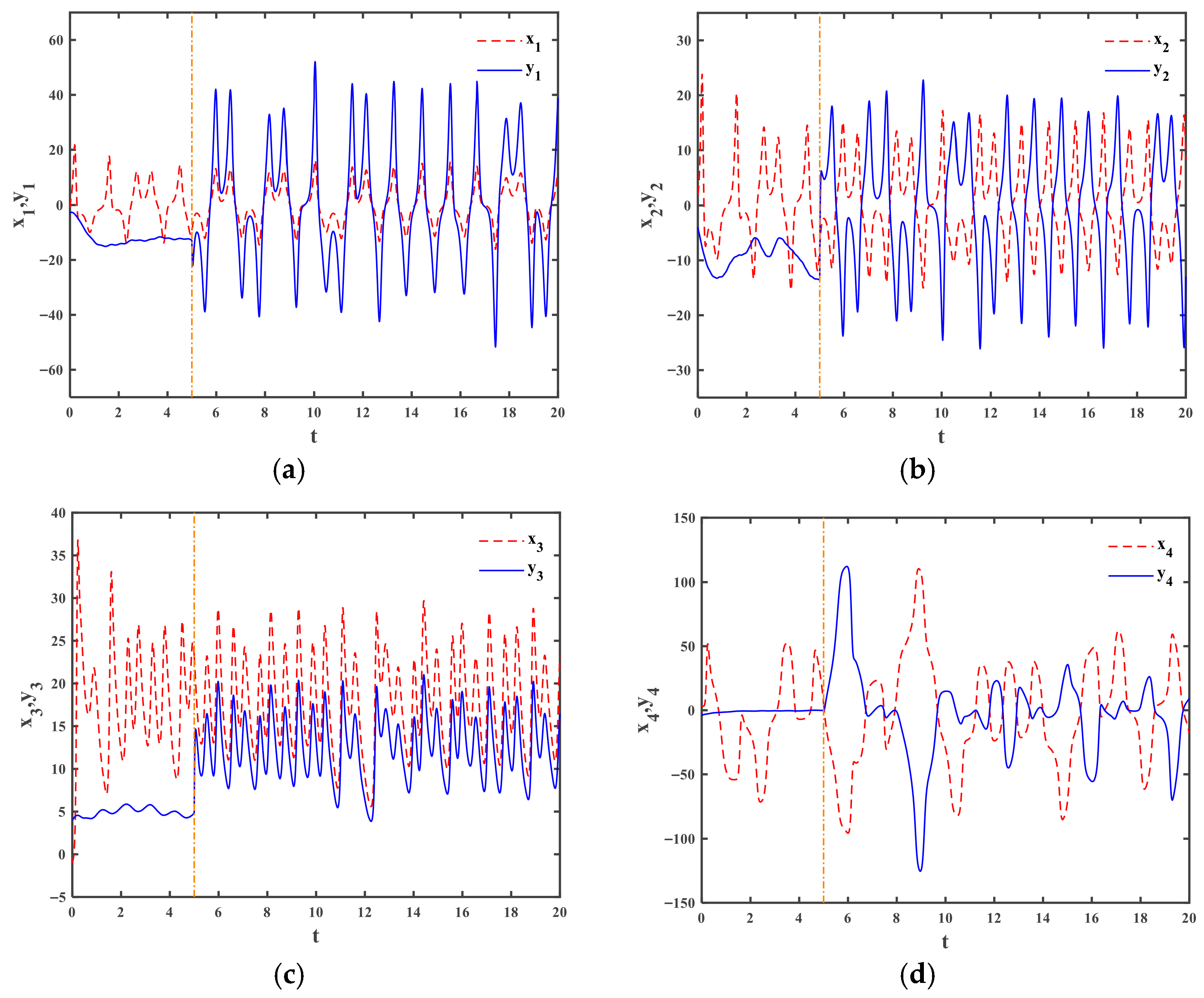
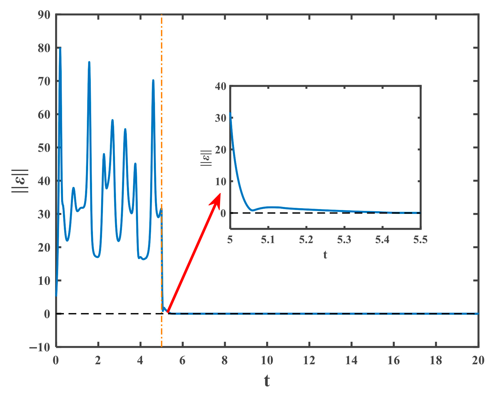
Before and after the action of the controller (9), the state trajectories of the drive system (14) and response system (15) are exhibited in Figure 4. We can observe that the drive and response systems successfully implement the MFPS within a short period of time after the controller is activated at t = 5 . The time response of synchronization error is depicted in Figure 5. One can clearly see that after applying the controller for about 0.3 , the synchronization error quickly converges to zero, which further verifies that the drive and response systems can achieve synchronization according to the specified scaling function factors. In order to more intuitively display the behavior of MFPS, Figure 6 presents the phase trajectories of the drive system and the response system.

4.2. The Drive and Response Systems with Noise Disturbance

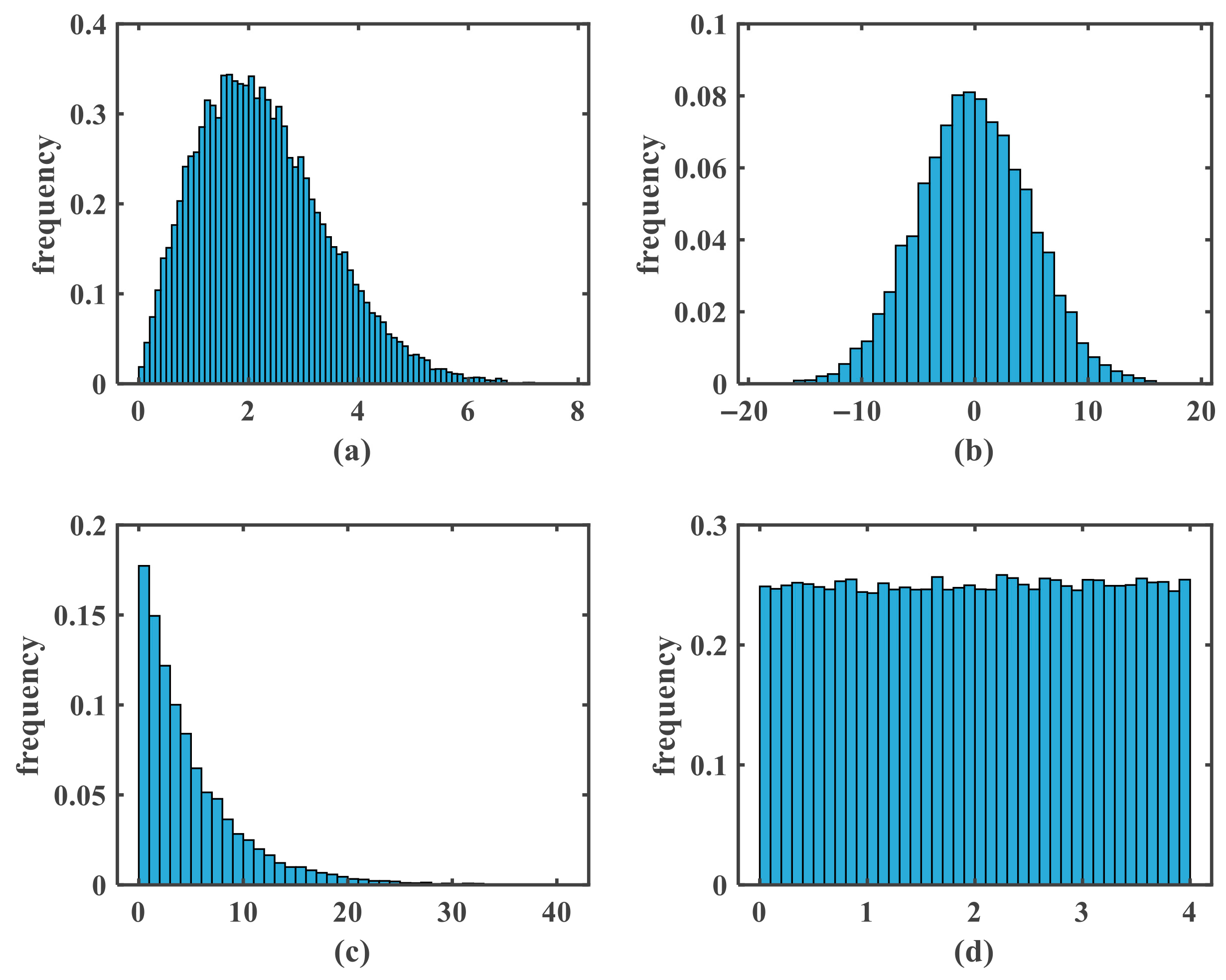
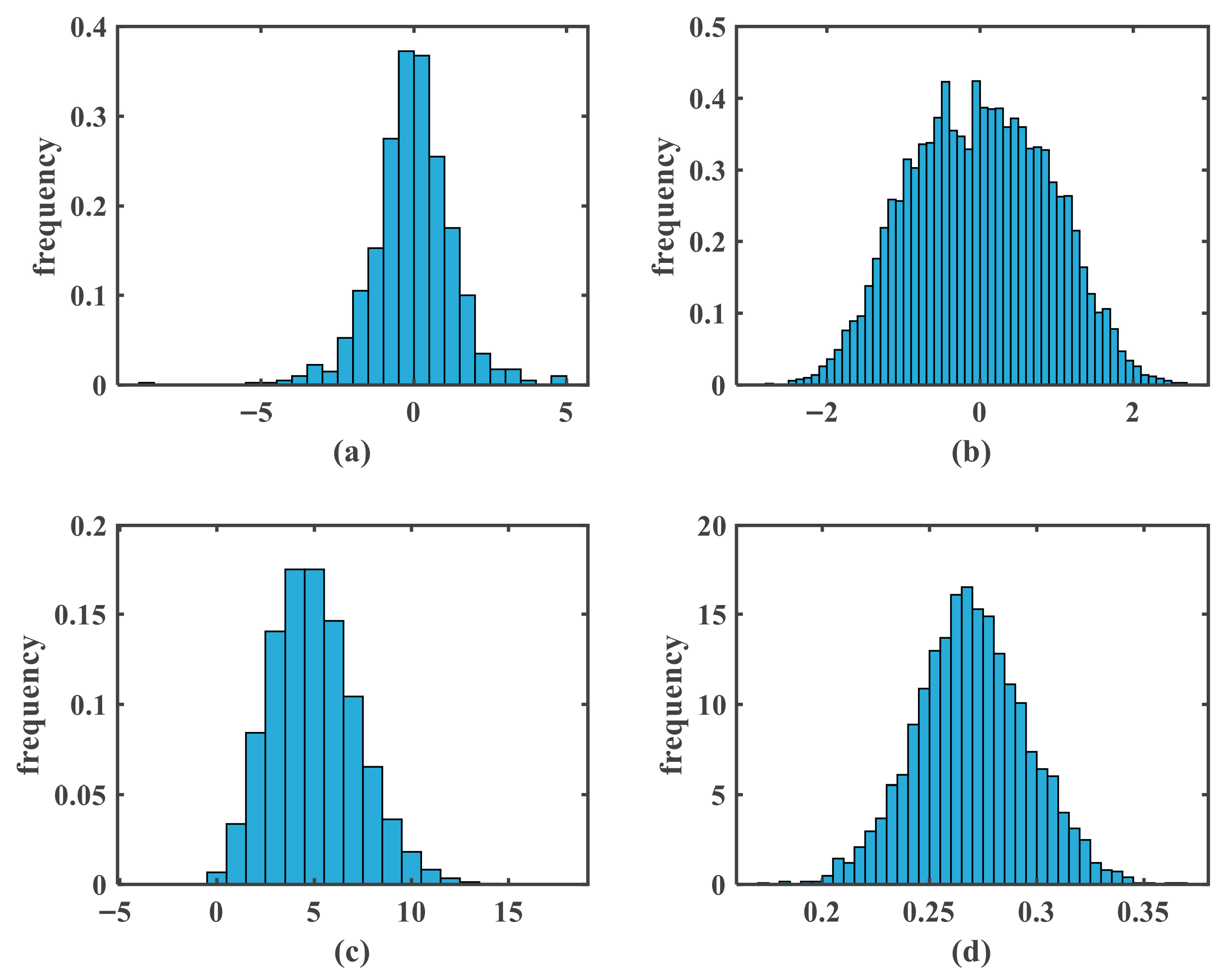
In this example, the external disturbances of the drive system (14) and response system (15) are noise disturbances, which are Rayleigh noise, Gaussian noise, Gamma noise, Uniform noise, Cauchy noise, Gaussian white noise, Poisson noise, and Beta noise in sequence. The corresponding means and variances of the above noise are exhibited in Table 1, and the histograms are shown in Figure 7 and Figure 8. Figure 9 and Figure 10, respectively, demonstrate the state and error trajectories of the MFPS of the drive and response systems with noise disturbances based on the proposed control technique. As illustrated in these figures, after a short period of time, the synchronization error converges to zero and the response system follows the drive system precisely according to the corresponding functional scaling factors.
Based on the simulation results under the above two disturbances, it can be strongly confirmed that the proposed control scheme can effectively synchronize different fractional-order hyperchaotic and chaotic systems in the presence of complex disturbances.

4.3. The Effect of RBF Neural Network Parameters

In the realization of MFPS for fractional-order chaotic systems, the RBF neural network is utilized for the first time to estimate the model uncertainties and external disturbances, with its network parameters potentially affecting the effectiveness of MFPS. Therefore, this section will take periodic disturbances as an example to further explore the specific effects of two key parameters of RBF neural network, namely the center vector C and width B of Gaussian basis function (2), on the performance of MFPS.
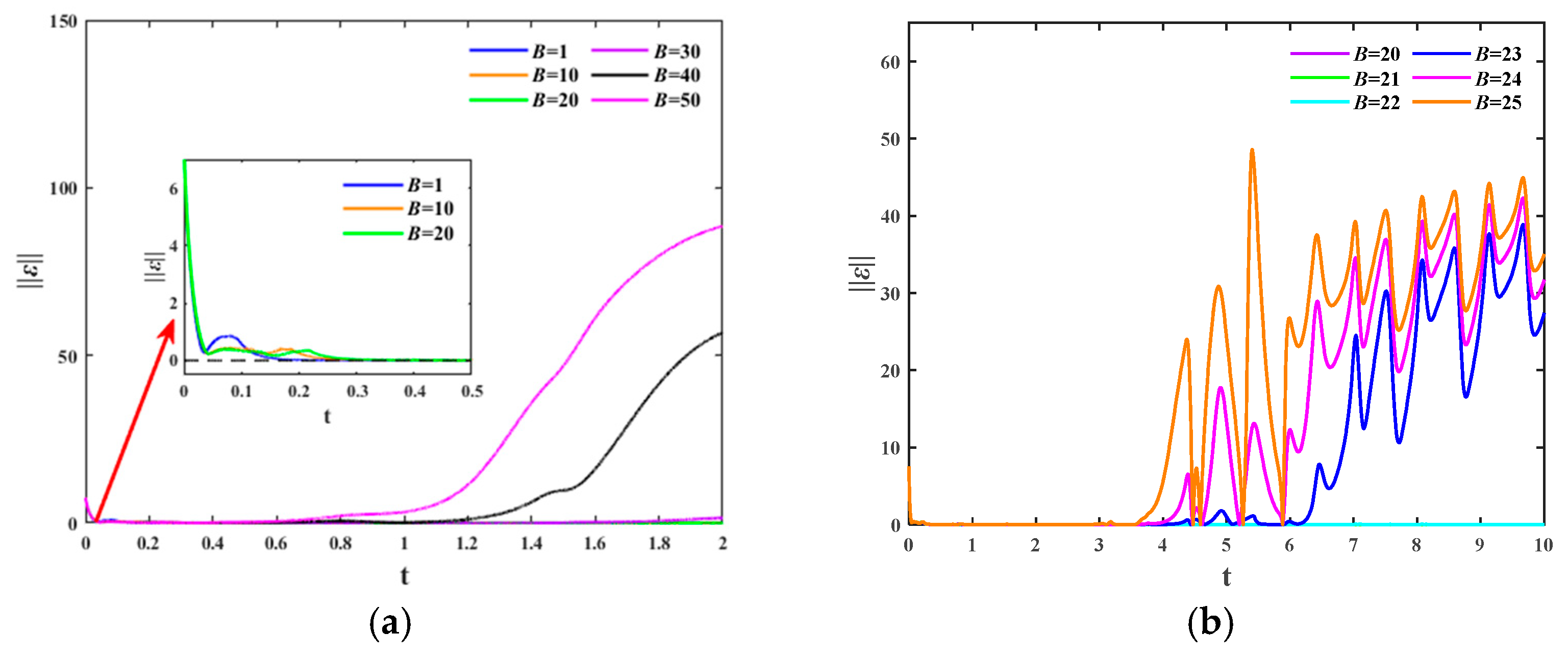
When C = [ 1 , 1 , 1 , 1 , 1 , 1 , 1 ] and the value of B changes, the time history of MFPS error is displayed in Figure 11. It is not difficult to see from Figure 11a that there exists a critical value B * [ 20 , 30 ) , and the MFPS error will converge to zero with B B * . Moreover, the smaller B , the faster the convergence speed. On the contrary, the MFPS error will not converge to zero with B > B * . The critical value B * 22 can be obtained through further calculations, as shown in Figure 11b.
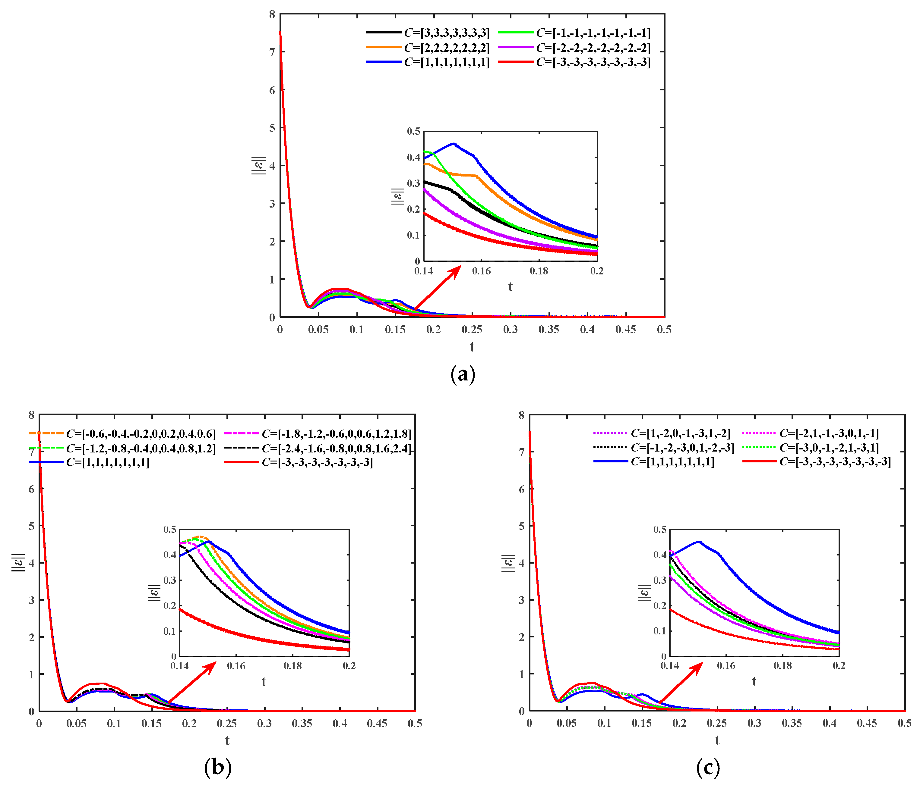
When B = 5 and the value of C changes, the time history of MFPS error is exhibited in Figure 12. Firstly, as observed in Figure 12a, when the elements of C are identical and positive, the convergence speed of MFPS error gradually faster with the increase in its value. Conversely, when the elements of C are negative, the larger its absolute value, the faster the convergence speed of MFPS error. It is worth noting that when all elements of C are negative, the convergence speed is faster than when all elements are positive. Specifically, the slowest convergence of MFPS error is C = [ 1 , 1 , 1 , 1 , 1 , 1 , 1 ] , while the fastest convergence is C = [ 3 , 3 , 3 , 3 , 3 , 3 , 3 ] . Secondly, from Figure 12b, it can be seen that when the differences between adjacent elements of C are identical, a larger difference results in a faster convergence speed of MFPS error. Finally, as shown in Figure 12c, when the elements of C take arbitrary values, the convergence speed of MFPS error is similar.
Based on the above conclusion, it can be concluded that the values of width B and center vector C have significant impacts on MFPS performance, with B exerting a greater influence. Therefore, appropriate parameter values can be selected to achieve the desired synchronization control effect in practical applications.

5. Image Cryptography Based on the Finite-Time MFPS

In this section, a novel color image cryptography technique will be developed based on the MFPS between fractional-order hyperchaotic Chen system (14) and fractional-order chaotic entanglement system (15).

5.1. Proposed Encryption and Decryption Scheme

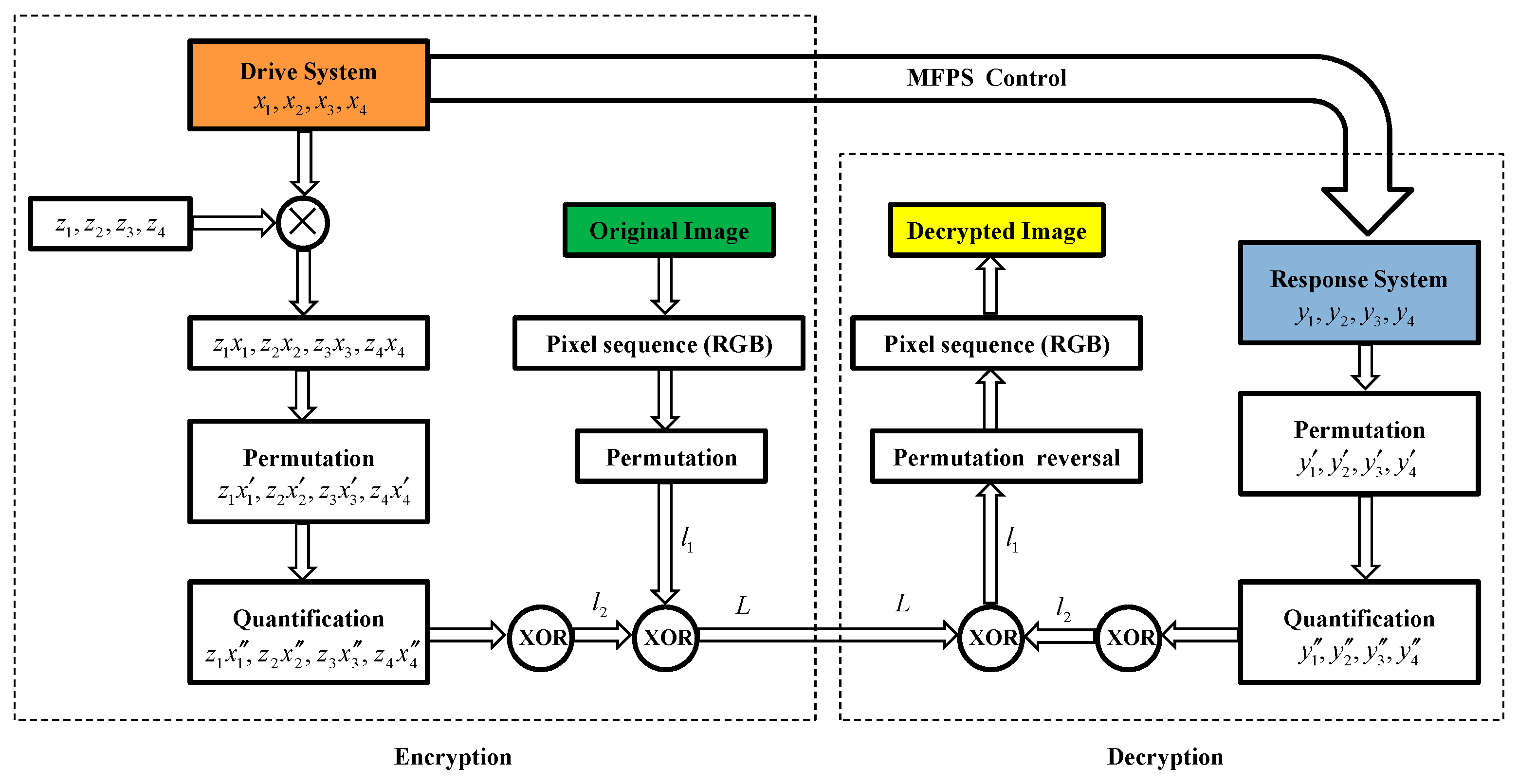
The main framework of the color image encryption and decryption scheme is presented in Figure 13. The detailed operation process of the scheme is summarized as follows:
A. Encryption Process (Sender Side):
Step 1. Permutation of chaotic sequences
When MFPS is achieved, we first extract the hyperchaotic sequences x 1 , x 2 , x 3 , x 4 from the drive system (14) and multiply them by the scaling function factors z 1 , z 2 , z 3 , z 4 , respectively. Then, the sequences z 1 x 1 , z 2 x 2 , z 3 x 3 , z 4 x 4 are iterated and cut separately to ensure that the length of each sequence is exactly m × n × 3 . Subsequently, these chaotic sequences are randomly permutated to obtain z 1 x 1 , z 2 x 2 , z 3 x 3 , z 4 x 4 .
Step 2. Quantification of chaotic sequences
Since the pixel values of each color channel is an integer between 0 and 255, the above hyperchaotic sequences are normalized and then mapped to the integer range of [0, 255], as described below:
z i x i = floor 255 z i x i min ( z i x i ) max ( z i x i ) min ( z i x i ) , i = 1 , , 4 ,
where floor(·) means to take the largest integer less than or equal to x .
Step 3. Read plaintext image
Consider a color plaintext image of size m × n × 3 , and extract its R (red), G (green) and B (blue) channels, each of which is a two-dimensional matrix of size m × n , and then transformed into three one-dimensional vectors.
Step 4. Permutation of the image sequence
The one-dimensional vectors of the R, G and B channels are randomly permutated, and then these three permutated vectors are combined alternately in the order of R, G and B to form a new one-dimensional vector of length m × n × 3 , namely l 1 .
Step 5. XOR operations
To further enhance randomness and security, logical XOR operations are performed between hyperchaotic sequences z 1 x 1 , z 2 x 2 , z 3 x 3 , z 4 x 4 to generate the sequence l 2 . Then, XOR l 2 with the permutated image sequence l 1 again to obtain the final transmitted sequence L . The specific XOR operation process is as follows:
L = ( z 1 x 1 z 2 x 2 ) z 3 x 3 z 4 x 4 l = l 2 l 1 ,
where L is encrypted image sequence.
B. Decryption Process (Receiver Side):
Step 1′. Permutation of chaotic sequences
When MFPS are achieved, we first extract the chaotic sequences y 1 , y 2 , y 3 , y 4 from the response system (15) and cut separately to ensure that the length of each sequence is exactly m × n × 3 . Subsequently, these chaotic sequences are randomly permutated to obtain y 1 , y 2 , y 3 , y 4 , where the permutation matrix is the inverse matrix of the permutation matrix in step 1 of the encryption process.
Step 2′. Quantification of chaotic sequences
Similarly, the above chaotic sequences are normalized and then mapped to the integer range of [0, 255], as described below:
y i = floor 255 y i min ( y i ) max ( y i ) min ( y i ) , i = 1 , , 4 .
Step 3′. XOR operations
Perform XOR operations between chaotic sequences y 1 , y 2 , y 3 , y 4 to obtain sequence l 2 , and then XOR it again with the transmitted sequence L in the channel to obtain l 1 . The specific XOR operation process is as follows:
l 1 = ( y 1 y 2 ) y 3 y 4 L = l 2 L .
Step 4′. Reverse permutation image sequence
Divide the one-dimensional vector l 1 of length m × n × 3 into three groups in the order R, G and B, yielding three one-dimensional vectors each of length m × n . Then, permute these vectors, where the permutation matrix is the inverse matrix of the permutation matrix in step 4 of the encryption process, to obtain the three original one-dimensional vectors.
Step 5′. Restore plaintext image
Based on the inverse transformation in step 3 of the encryption process, the above three vectors are restored to two-dimensional matrices for the R, G and B channels, thereby obtaining the pixel matrix of the original image.

5.2. Simulated Experiments

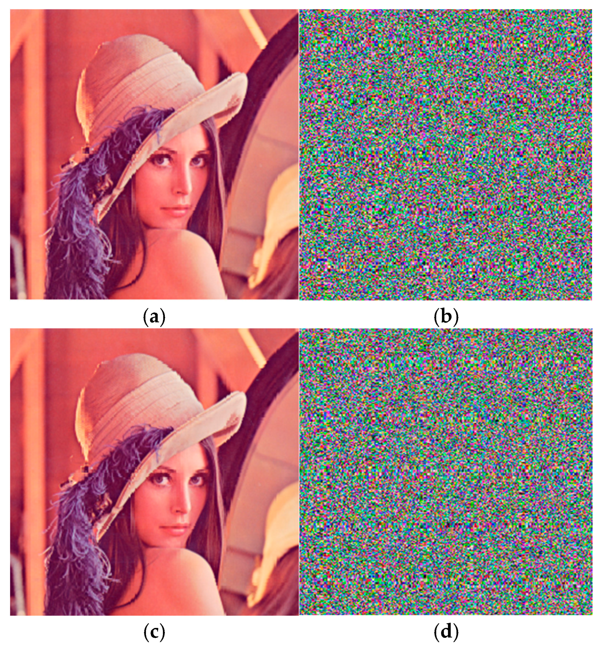
In this section, the Lena color images with a size of 256 × 256 × 3 are selected as the test images for encryption and decryption scheme. The drive system and response system employ the scenario with noise disturbances described in Section 4.2, resulting in the encrypted image sequence L containing multiple types of noise disturbances. The original image and encrypted image are depicted in Figure 14a,b, and it is evident the encrypted image no longer contains any useful information that can directly identify the original image. Furthermore, when we adopt the correct key for the decryption operation, Figure 14c successfully and clearly recovers the original image, which verifies the effectiveness of the designed decryption algorithm. It also demonstrates that the algorithm exhibits a certain degree of robustness against noise disturbances.
On the other hand, it is also noticed that during the decryption process, if an incorrect key is used, such as replacing the XOR operation from l 1 = ( y 1 y 2 ) y 3 y 4 L to l 1 = y 1 L in step 3′, then the image cannot be successfully recovered, as shown in Figure 14d, which demonstrates the security of the proposed scheme in image transmission. Here, y 1 , y 2 , y 3 , y 4 represents the chaotic sequence from the response system (15) after correct permutation and quantization, while L and l 1 are the encrypted and decrypted one-dimensional image sequences, respectively.

5.3. Statistics and Security Analysis

In order to evaluate the security and performance of the new image encryption algorithm, the key space analysis and a series of statistical analysis including histogram, adjacent pixels correlation, and information entropy are carried out in this section.

5.3.1. Key Space Analysis

The key space of an image encryption scheme is the set of all possible keys in the scheme. Firstly, since the chosen response system (15) is our proposed 4D fractional-order chaotic entanglement system, its parameters a , b , c , d , e 1 , e 2 , e 3 , e 4 can be keys. The initial values X ( 0 ) = x 10 , x 20 , x 30 , x 40 , and differential orders q 1 , q 2 can also be regarded as keys. The chaotic sequences X = x 1 , x 2 , x 3 , x 4 and Y = y 1 , y 2 , y 3 , y 4 generated implementing the MFPS are the keys, and the start time t s t a r t of the selected synchronized chaotic sequences is also the key. The scaling function matrix Z ( t ) = d i a g z 1 ( t ) , z 2 ( t ) , , z n ( t ) is also an extremely important key. The randomized permutation order I i ( i = 1 , 2 , 3 , 4 ) of the one-dimensional vectors of R, G and B channels in step 1 and the randomized permutation order I i ( i = 5 , 6 , 7 ) of the chaotic sequences in step 4 are considered as the keys. In addition, the XOR operation rules in step 5 are also taken as a key.
To summarize, the total key space of the proposed image encryption scheme is as follows
K = a , b , c , d , e 1 , e 2 , e 3 , e 4 , q 1 , q 2 , t s t a r t , X 0 , Y 0 , X , Y , Z ( t ) , I i ( i = 1 , 2 , , 7 ) , XOR ,
which aligns with current cryptographic practices, and the key length is considered sufficient to effectively resist known brute-force attacks.

5.3.2. Histogram Analysis

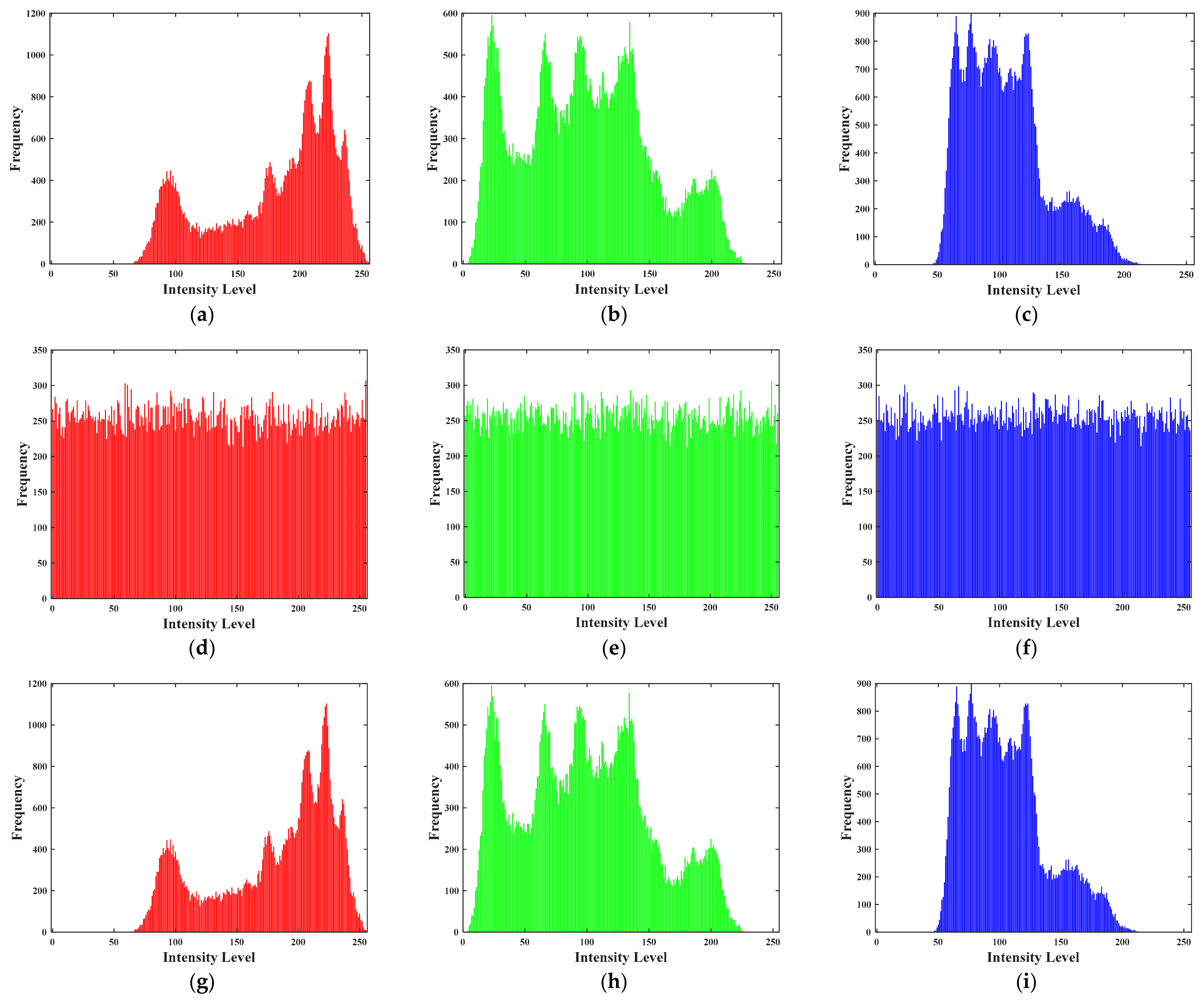
The histogram visualizes the statistical information of the image and reflects the distribution of pixel intensities in the image. An effective encryption scheme should be able to generate encrypted images with a uniform distribution histogram. The histograms of the R, G and B channels of the original, encrypted and decrypted images are exhibited in Figure 15. It can be observed that the histograms of the R, G, and B channels of the encrypted image present a uniform distribution, which indicates that the proposed encryption scheme possesses high resistance to any statistical attacks. Furthermore, we also see that the histogram distribution of the R, G and B channels of the decrypted image is consistent with that of the original image, which verifies the effectiveness of the decryption scheme.

5.3.3. Adjacent Pixel Correlation Analysis

The correlation coefficient between adjacent pixels is a useful statistical feature of an image, which reveals the spatial correlation of pixels. An effective image encryption algorithm should break the strong correlation between adjacent pixels in different directions. The correlation coefficient r x y is defined by the following equation:
r x y = cov ( x , y ) D ( x ) D ( y ) ,
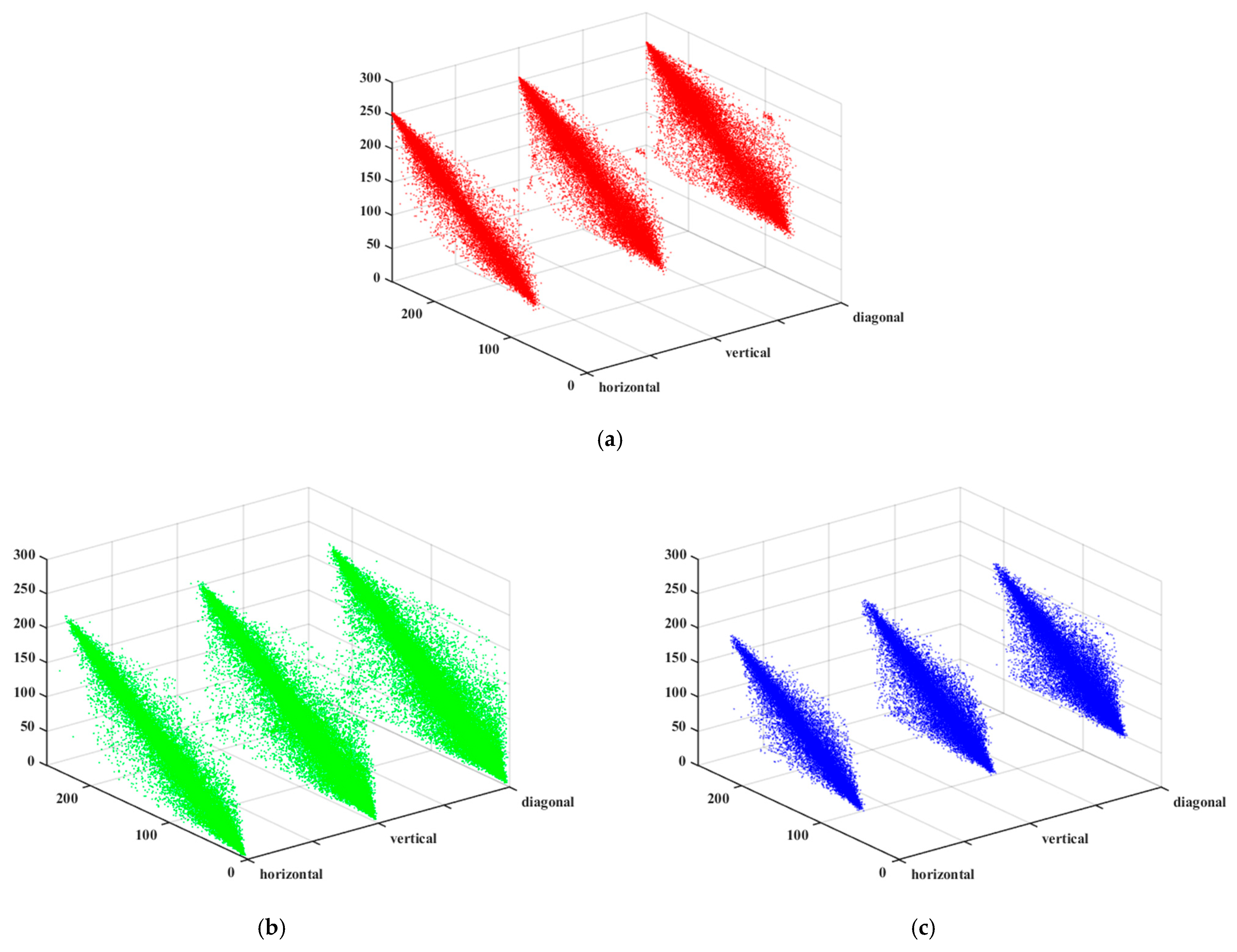
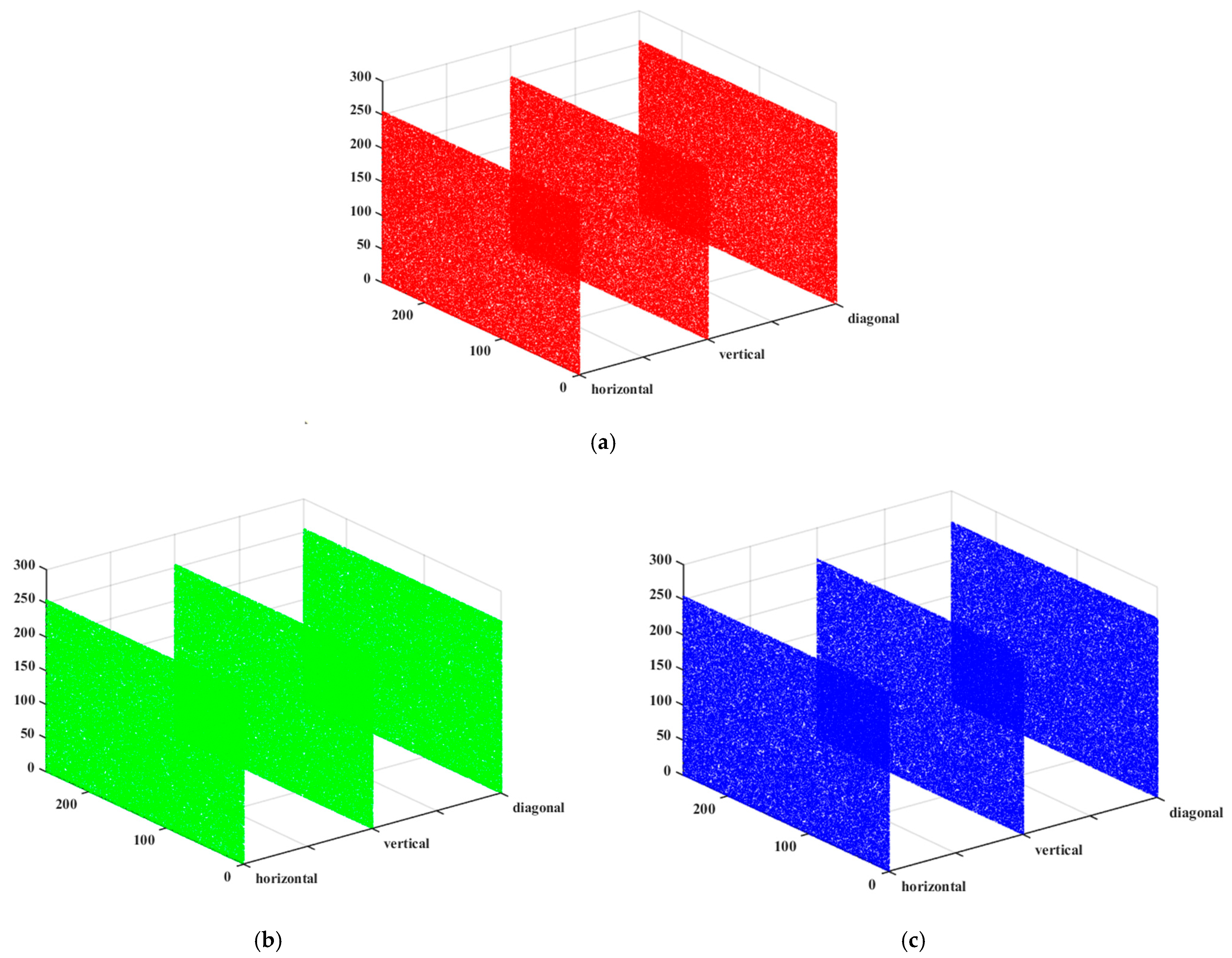
We randomly select pairs of adjacent pixels from the horizontal, vertical and diagonal directions of each color channel of the original and encrypted images, respectively. The correlation coefficients before and after encryption are provided in Table 2. It can be seen that the correlation coefficients of the encrypted images are close to 0, indicating minimal correlation between adjacent pixels. Additionally, a comparison has been conducted with the correlation coefficients of encrypted images in the confidential communication scheme described in Ref. [51], further demonstrating the enhanced encryption performance. Figure 16 and Figure 17 illustrate the relationship between adjacent pixels in the horizontal, vertical and diagonal directions for each color channel in the original and encrypted images, respectively. It is evident that the adjacent pixels in the original image have obvious correlation, while the correlation between neighboring pixels in the encrypted image has been eliminated. It is visually confirmed that the high security of the proposed encryption scheme against correlation attacks.

5.3.4. Information Entropy Analysis

Information Entropy (IE) is a central concept introduced by Claude Shannon in information theory, which is used to quantitatively describe the degree of uncertainty or randomness within a given complex system. In the field of image encryption, information entropy is applied to measure and evaluate the strength and security of image encryption scheme. For a sequence of pixel values x = x 1 , x 2 , , x M , the mathematical equation for IE is presented as follows:
I E ( x ) = i = 1 M P ( x i ) log 2 P ( x i ) ,
where P ( x i ) represents the probability of the pixel value x i
In this work, the pixel value of each color channel of the original image is when the pixel values occur with equal probability, the IE value reaches a maximum value of 8, which is the desired value for the encrypted image. Based on the above formula, one can obtain the IE value for each color channel of the original and encrypted images, as shown in Table 3. It can be seen that the proposed image encryption algorithm demonstrated superior performance, achieving entropy values of 7.9903, 7.9891, and 7.9893 for the red, green, and blue channels, respectively, approaching the theoretical maximum entropy value of 8.0000. This indicates that the algorithm effectively increases the randomness of image data across all three channels, thereby enhancing image security. At the same time, by comparing the information entropy of encrypted images with the confidential communication scheme in [51], it was found that their encryption performance is nearly identical.

6. Conclusions

Firstly, fractional-order chaotic systems are modeled using fractional calculus, which can describe dynamic processes exhibiting memory and heredity-characteristics present in the vast majority of physical, chemical, and biological systems. Compared to integer-order systems, studying synchronization control of fractional-order systems can more accurately reflect and apply to the real world. Secondly, modified function projection synchronization (MFPS) represents an extension of function projection synchronization (FPS), which itself is an extension of projection synchronization. In secure communication, the time-varying, non-constant scaling function matrix in MFPS can serve as an additional key. Even if attackers crack the chaotic system itself, they cannot extract information correctly without knowing the specific form of greatly enhancing the confidentiality of the communication system. This research combines the modeling advantages of fractional-order systems with the methodological strengths of MFPS, which not only advances the development of fractional-order control theory but also holds significant application value in secure communications and signal processing.
To be more specific, a new fractional-order sliding mode controller is designed for the finite-time MFPS problem of different fractional order chaotic systems in this paper. The controller incorporates an RBF neural network to approximate the uncertainty terms and external disturbances in the model. Based on Lyapunov stability theory, it is proved that the synchronized error system can reach the sliding mode surface rapidly and converge to zero along the sliding mode surface in a finite time. In order to verify the effectiveness of the proposed method, numerical simulations are carried out with periodic perturbation and noise disturbance conditions, respectively, both of which realize the finite-time MFPS for fractional-order hyperchaotic Chen systems and fractional-order chaotic entanglement systems. In addition, the specific effects of the neural network parameters on the performance of the MFPS are also analyzed in detail, and the results show that the synchronization control can be further optimized by choosing suitable parameter values. Finally, a new image encryption scheme is designed using XOR operation, which effectively implements the encryption and decryption process of color images. In addition, the image encryption scheme shows satisfactory performance in terms of key space size, histogram uniformity, neighboring pixel correlation, and information entropy, which fully demonstrates its effectiveness. However, its broader applicability still needs to be validated in the future through more diverse and complex scenarios.
Based on the completed work outlined above, subsequent research will advance in the following directions. Firstly, this paper focuses on commensurate fractional-order chaotic systems, which are characterized by each state variable having the same differential order. In the future, we plan to extend the proposed finite-time MFPS control method to incommensurate fractional-order chaotic systems, thereby enriching the synchronization control methodology of fractional-order chaotic systems. Secondly, we have conducted key space analysis, noise perturbation analysis, and statistical evaluations of the proposed image encryption scheme. Future efforts will continue to optimize this confidential communication scheme and perform more comprehensive and rigorous security assessment. Finally, we will apply the MFPS theory of fractional-order chaotic system to fields such as biology, physics, and finance. For instance: investigating synchronization mechanisms in biological neural networks to uncover brain information processing patterns; exploring applications of chaos synchronization in fluid mechanics and plasma physics; and constructing financial risk early-warning models based on chaotic synchronization to enhance market prediction accuracy.

Author Contributions

Conceptualization was carried out by R.L.; the methodology was developed by R.L. and H.W.; software was provided and maintained by R.L. and H.W.; writing—original draft preparation, R.L. and H.W.; writing—review and editing, R.L. and D.H.; funding acquisition, D.H. All authors have read and agreed to the published version of the manuscript.

Funding

This research was funded by the National Natural Science Foundation of China under Grant No. 12172266.

Institutional Review Board Statement

Not applicable.

Informed Consent Statement

Not applicable.

Data Availability Statement

The data supporting the findings of this study are fully included within the article.

Conflicts of Interest

The authors declare no conflicts of interest.

Abbreviations

The following abbreviations are used in this manuscript:
FPSfunction projection synchronization
MFPSmodified function projection synchronization
RBFradial basis function
IEInformation Entropy

References

  1. Podlubny, I. Fractional Differential Equations; Academic Press: San Diego, CA, USA, 1999. [Google Scholar]
  2. Kilbas, A.A.; Srivastava, H.M.; Trujillo, J. Theory and Applications of Fractional Differential Equations; Elsevier: Amsterdam, The Netherlands, 2006. [Google Scholar]
  3. Diethelm, K.; Kiryakova, V.; Luchko, Y.; Machado, J.A.T.; Tarasov, V.E. Trends, directions for further research, and some open problems of fractional calculus. Nonlinear Dyn. 2022, 107, 3245–3270. [Google Scholar] [CrossRef]
  4. Sun, H.G.; Zhang, Y.; Baleanu, D.; Chen, W.; Chen, Y.Q. A new collection of real world applications of fractional calculus in science and engineering. Commun. Nonlinear Sci. Numer. Simul. 2018, 64, 213–231. [Google Scholar] [CrossRef]
  5. Wang, H. Research on application of fractional calculus in signal real-time analysis and processing in stock financial market. Chaos Soliton Fract. 2019, 128, 92–97. [Google Scholar]
  6. Sakariya, H.; Prasad, R.S.; Kumar, S. A study on brain tumor dynamics in two-dimensional irregular domain with variable-order time-fractional derivative. Comput. Meth. Prog. Bio. 2005, 264, 108700. [Google Scholar]
  7. Fu, L.X.; Zhu, W.T.; Yu, B.; Zhang, Y.Y.; Sosa, P.A.V.; Li, C.B.; Ricci, L.; Frasca, M.; Minati, L. Modeling and experimental circuit implementation of fractional single-transistor chaotic oscillators. Appl. Math. Comput. 2025, 500, 129438. [Google Scholar] [CrossRef]
  8. Lenka, B.K.; Upadhyay, R.K. Hidden memory chaotic attractors in simple nonequilibrium fractional order systems. Commun. Nonlinear Sci. Numer. Simulat. 2025, 150, 108970. [Google Scholar]
  9. Tavazoei, M.S. Fractional order chaotic systems: History, achievements, applications, and future challenges. Eur. Phys. J.-Spec. Top. 2020, 229, 887–904. [Google Scholar]
  10. Pecora, L.M.; Carroll, T.L. Synchronization in chaotic systems. Phys. Rev. Lett. 1990, 64, 821–824. [Google Scholar] [CrossRef] [PubMed]
  11. Mahmoud, G.M.; Mahmoud, E.E. Complete synchronization of chaotic complex nonlinear systems with uncertain parameters. Nonlinear Dyn. 2010, 62, 875–882. [Google Scholar] [CrossRef]
  12. Chishti, S.; Ramaswamy, R. Design strategies for generalized synchronization. Phys. Rev. E 2018, 98, 032217. [Google Scholar] [CrossRef]
  13. Wei, X.F.; Zhang, Z.Y.; Lin, C.; Chen, J. Synchronization and anti-synchronization for complex-valued inertial neural networks with time-varying delays. Appl. Math. Comput. 2021, 403, 126194. [Google Scholar]
  14. Luan, H.Y.; Ouyang, Y.H.; Zhao, Z.W.; Mao, W.Z.; Ma, R.M. Reconfigurable moiré nanolaser arrays with phase synchronization. Nature 2023, 624, 282–288. [Google Scholar] [CrossRef] [PubMed]
  15. Mainieri, R.; Rehacek, J. Projective synchronization in three-dimensional chaotic systems. Phys. Rev. Lett. 1999, 82, 3042–3045. [Google Scholar] [CrossRef]
  16. Si, G.Q.; Sun, Z.Y.; Zhang, Y.B.; Chen, W.Q. Projective synchronization of different fractional-order chaotic systems with non-identical orders. Nonlinear Anal. Real World Appl. 2012, 13, 1761–1771. [Google Scholar]
  17. Du, H.Y.; Zeng, Q.S.; Wang, C.H. Function projective synchronization of different chaotic systems with uncertain parameters. Phys. Lett. A 2008, 372, 5402–5410. [Google Scholar] [CrossRef]
  18. Wang, C.; Zhang, H.L.; Fan, W.H.; Ma, P. Finite-time function projective synchronization control method for chaotic wind power systems. Chaos Soliton Fract. 2020, 135, 109756. [Google Scholar] [CrossRef]
  19. Du, H.Y.; Zeng, Q.S.; Wang, C.H. Modified function projective synchronization of chaotic system. Chaos Soliton Fract. 2009, 42, 2399–2404. [Google Scholar]
  20. Tran, X.T.; Kang, H.J. A novel observer-based finite-time control method for modified function projective synchronization of uncertain chaotic (hyperchaotic) systems. Nonlinear Dyn. 2015, 80, 905–916. [Google Scholar] [CrossRef]
  21. Dessoky, M.M.E.; Almohammadi, N.; Alzahrani, E. Control and adaptive modified function projective synchronization of different hyperchaotic dynamical systems. AIMS Math. 2023, 8, 23621–23634. [Google Scholar] [CrossRef]
  22. Liu, S.T.; Zhang, F.F. Complex function projective synchronization of complex chaotic system and its applications in secure communication. Nonlinear Dyn. 2014, 76, 1087–1097. [Google Scholar]
  23. Tirandaz, H.; Mollaee, A.K. Modified function projective feedback control for time-delay chaotic Liu system synchronization and its application to secure image transmission. Optik 2017, 147, 187–196. [Google Scholar] [CrossRef]
  24. Sudheer, K.S.; Sabir, M. Modified function projective synchronization of hyperchaotic systems through Open-Plus-Closed-Loop coupling. Phys. Lett. A 2010, 374, 2017–2023. [Google Scholar] [CrossRef]
  25. He, J.M.; Wu, Y.P.; Yang, C.S. Function matrix projective synchronization for disturbed fractional laser chaotic systems and image encryption. Chin. J. Phys. 2025, 95, 1078–1095. [Google Scholar] [CrossRef]
  26. Zhou, P.; Ding, R. Adaptive function projective synchronization between different fractional-order chaotic systems. Indian J. Phys. 2012, 86, 497–501. [Google Scholar] [CrossRef]
  27. Geng, L.L.; Yu, Y.G.; Zhang, S. Function projective synchronization between integer-order and stochastic fractional-order nonlinear systems. ISA Trans. 2016, 64, 34–46. [Google Scholar] [CrossRef]
  28. Ouannas, A.; Grassi, G.; Ziar, T.; Odibat, Z. On a function projective synchronization scheme for non-identical fractional-order chaotic (hyperchaotic) systems with different dimensions and orders. Optik 2017, 136, 513–523. [Google Scholar] [CrossRef]
  29. Du, H.Y. Modified function projective synchronization between two fractional-order complex dynamical networks with unknown parameters and unknown bounded external disturbances. Phys. A 2019, 526, 120997. [Google Scholar] [CrossRef]
  30. Dessoky, M.M.E.; Khan, M.A. Application of fractional calculus to combined modified function projective synchronization of different systems. Chaos 2019, 29, 013107. [Google Scholar] [CrossRef] [PubMed]
  31. He, J.M.; Pei, L.J. Function matrix projection synchronization for the multi-time delayed fractional order memristor-based neural networks with parameter uncertainty. Appl. Math. Comput. 2023, 454, 128110. [Google Scholar] [CrossRef]
  32. Amato, F.; Ariola, M. Finite-time control of discrete-time linear systems. IEEE Trans. Autom. Control 2005, 50, 724–729. [Google Scholar] [CrossRef]
  33. Bhat, S.P.; Bernstein, D.S. Finite-time stability of continuous autonomous systems. SIAM J. Control Optim. 2000, 38, 751–766. [Google Scholar] [CrossRef]
  34. Ai, C.Y.; He, S.; Wang, W.Q.; Fan, X.C. Finite time adaptive synchronous control for fractional-order chaotic power systems. IET Gener. Transm. Dis. 2023, 17, 3626–3637. [Google Scholar] [CrossRef]
  35. Lin, F.N.; Xue, G.M.; Qin, B.; Li, S.G.; Liu, H. Event-triggered finite-time fuzzy control approach for fractional-order nonlinear chaotic systems with input delay. Chaos Soliton Fract. 2023, 175, 114036. [Google Scholar] [CrossRef]
  36. Aghababa, M.P. Finite-time chaos control and synchronization of fractional-order nonautonomous chaotic (hyperchaotic) systems using fractional nonsingular terminal sliding mode technique. Nonlinear Dyn. 2012, 69, 247–261. [Google Scholar] [CrossRef]
  37. Delavari, H.; Mohadeszadeh, M. Robust finite-time synchronization of non-identical fractional-order hyperchaotic systems and its application in secure communication. IEEE/CAA J. Autom. Sinica 2019, 6, 228–235. [Google Scholar] [CrossRef]
  38. Taheri, M.; Chen, Y.C.; Zhang, C.Q.; Berardehi, Z.R.; Roohi, M.; Khooban, M.H. A finite-time sliding mode control technique for synchronization chaotic fractional-order laser systems with application on encryption of color images. Optik 2023, 285, 170948. [Google Scholar] [CrossRef]
  39. Huang, L.L.; Li, W.Y.; Xiang, J.H.; Zhu, G.L. Adaptive finite-time synchronization of fractional-order memristor chaotic system based on sliding-mode control. Eur. Phys. J.-Spec. Top. 2022, 231, 3109–3118. [Google Scholar] [CrossRef]
  40. Wu, X.F.; Bao, H.B.; Cao, J.D. Finite-time inter-layer projective synchronization of Caputo fractional-order two-layer networks by sliding mode control. J. Frankl. Inst. 2021, 358, 1002–1020. [Google Scholar] [CrossRef]
  41. Liu, N.X.; Fei, J.T. Adaptive fractional sliding mode control of active power filter based on dual RBF neural networks. IEEE Access 2017, 5, 27590–27598. [Google Scholar] [CrossRef]
  42. Yousefpour, A.; Jahanshahi, H.; Pacheco, J.M.M.; Bekiros, S.; Wei, Z.C. A fractional-order hyper-chaotic economic system with transient chaos. Chaos Soliton Fract. 2020, 130, 109400. [Google Scholar] [CrossRef]
  43. Nian, F.Z.; Liu, X.M.; Zhang, Y.Q.; Yu, X.L. Module-phase synchronization of fractional-order complex chaotic systems based on RBF neural network and sliding mode control. Int. J. Mod. Phys. B 2020, 34, 2050050. [Google Scholar] [CrossRef]
  44. Yang, S.S.; Li, N. Chaotic behavior of a new fractional-order financial system and its predefined-time sliding mode control based on the RBF neural network. Electron. Res. Arch. 2025, 33, 2762–2799. [Google Scholar] [CrossRef]
  45. Camacho, N.A.; Mermoud, M.A.D.; Gallegos, J.A. Lyapunov functions for fractional order systems. Commun. Nonlinear Sci. Numer. Simulat. 2014, 19, 2951–2957. [Google Scholar] [CrossRef]
  46. Li, Y.; Chen, Y.Q.; Podlubny, I. Mittag-Leffler stability of fractional order nonlinear dynamic systems. Automatica 2009, 45, 1965–1969. [Google Scholar] [CrossRef]
  47. Wu, H.Q.; Wang, L.F.; Niu, P.F.; Wang, Y. Global projective synchronization in finite time of nonidentical fractional-order neural networks based on sliding mode control strategy. Neurocomputing 2017, 235, 264–273. [Google Scholar] [CrossRef]
  48. Wu, X.J.; Lu, Y. Generalized projective synchronization of the fractional-order Chen hyperchaotic system. Nonlinear Dyn. 2009, 57, 25–35. [Google Scholar] [CrossRef]
  49. Tang, X.Y.; Li, R.H.; Huang, D.M. A novel entanglement functions-based 4D fractional-order chaotic system and its bifurcation analysis. Phys. Scripta 2024, 99, 055251. [Google Scholar]
  50. Deng, W.H. Short memory principle and a predictor-corrector approach for fractional differential equations. J. Comput. Appl. Math. 2007, 206, 174–188. [Google Scholar] [CrossRef]
  51. Wei, F.; Chen, G.C.; Zeng, Z.G.; Gunasekaran, N. Finite/fixed-time synchronization of inertial memristive neural networks by interval matrix method for secure communication. Neural Netw. 2023, 167, 168–182. [Google Scholar] [CrossRef]
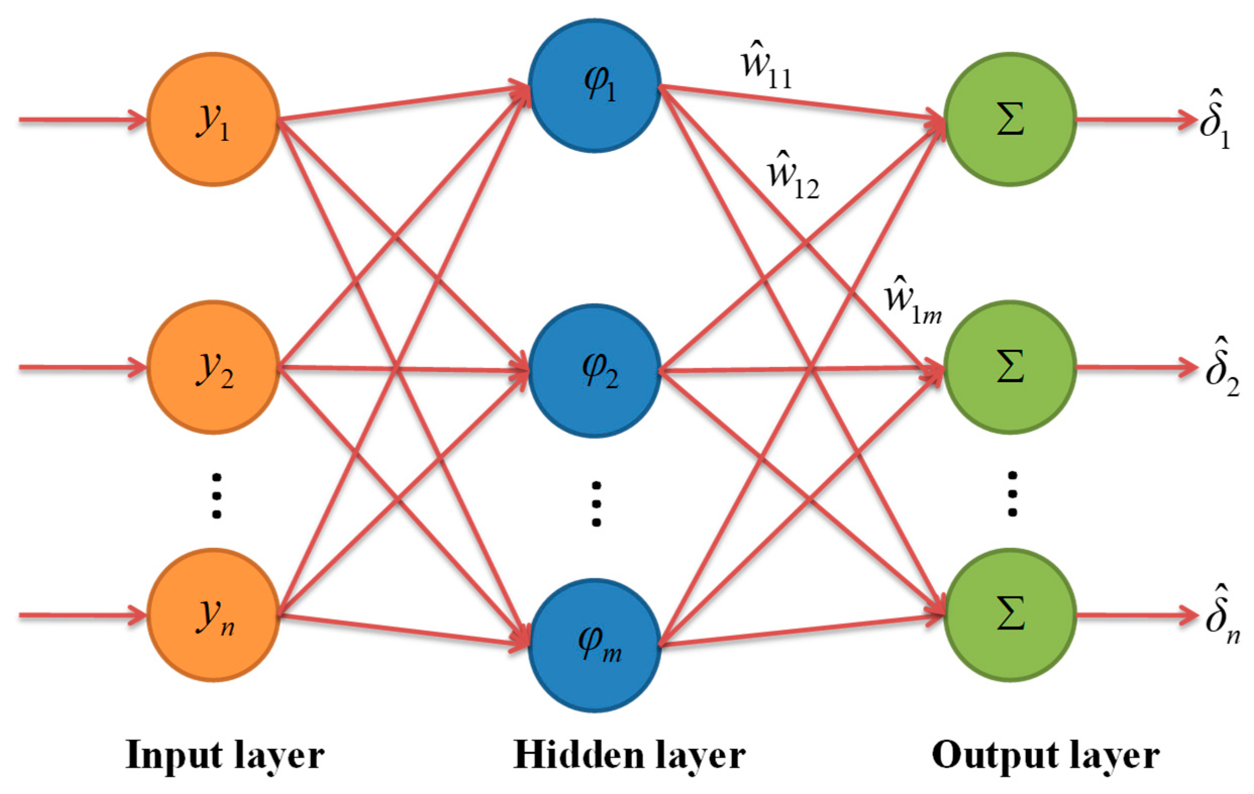
Figure 1. Structure of the RBF neural network.
Fractalfract 09 00659 g001
Figure 2. Hyperchaotic behavior of the 4D fractional-order Chen system: (a) two positive Lyapunov exponents; (b) phase diagram.
Fractalfract 09 00659 g002
Figure 3. Chaotic behavior of the 4D fractional-order entanglement system: (a) 0–1 test; (b) phase diagram.
Fractalfract 09 00659 g003
Figure 4. MFPS simulation diagrams of drive system (14) and response system (15) with periodic disturbances (the controller is activated at t = 5): ( a ) x 1 , y 1 ; ( b ) x 2 , y 2 ; ( c ) x 3 , y 3 ; ( d ) x 4 , y 4 .
Fractalfract 09 00659 g004aFractalfract 09 00659 g004b
Figure 5. Evolution of the synchronization error under periodic disturbances (the controller is activated at t = 5), where ε = e 1 2 + e 2 2 + e 3 2 + e 4 2 .
Fractalfract 09 00659 g005
Figure 6. Phase diagrams of drive system (14) and response system (15) with periodic disturbances based on the terminal sliding mode control with RBF neural network estimator: (a) x 2 x 3 x 1 ,   y 2 y 3 y 1 ; (b) x 1 x 2 , y 1 y 2 ; (c) x 2 x 3 , y 2 y 3 .
Fractalfract 09 00659 g006
Figure 7. Histograms of different noises of the drive system (14): (a) Rayleigh noise; (b) Gaussian noise; (c) Gamma noise; (d) Uniform noise.
Fractalfract 09 00659 g007
Figure 8. Histograms of different noises of the response system (15): (a) Cauchy noise; (b) Gaussian white noise; (c) Poisson noise; (d) Beta noise.
Fractalfract 09 00659 g008
Figure 9. MFPS simulation diagrams of drive system (14) and response system (15) with noise disturbances (the controller is activated at t = 5): ( a ) x 1 , y 1 ; ( b ) x 2 , y 2 ; ( c ) x 3 , y 3 ; ( d ) x 4 , y 4 .
Fractalfract 09 00659 g009
Figure 10. Evolution of the synchronization error under noise disturbances (the controller is activated at t = 5), where ε = e 1 2 + e 2 2 + e 3 2 + e 4 2 .
Fractalfract 09 00659 g010
Figure 11. State trajectories of the synchronization error with different values of B for C = [ 1 , 1 , 1 , 1 , 1 , 1 ] :   ( a ) B { 1 , 10 , 20 , 30 , 40 , 50 } ;   ( b ) B { 20 , 21 , 22 , 23 , 24 , 25 } .
Fractalfract 09 00659 g011
Figure 12. State trajectories of the synchronization error with different values of C for B = 5 : (a) identically valued; (b) uniformly valued; (c) arbitrarily valued.
Fractalfract 09 00659 g012
Figure 13. The flowchart of the image encryption and decryption scheme depending on MFPS.
Fractalfract 09 00659 g013
Figure 14. Image encryption and decryption test: (a) original image; (b) encrypted image; (c) decrypted image; (d) decrypted image with wrong keys.
Fractalfract 09 00659 g014
Figure 15. Image histogram: (a) R channel of original image; (b) G channel of original image; (c) B channel of original image; (d) R channel of encrypted image; (e) G channel of encrypted image; (f) B channel of encrypted image; (g) R channel of decrypted image; (h) G channel of decrypted image; (i) B channel of decrypted image.
Fractalfract 09 00659 g015
Figure 16. The correlation between the original image in horizontal direction, vertical direction, and diagonal direction: (a) R channel; (b) G channel; (c) B channel.
Fractalfract 09 00659 g016
Figure 17. The correlation between the encrypted image in horizontal direction, vertical direction, and diagonal direction: (a) R channel; (b) G channel; (c) B channel.
Fractalfract 09 00659 g017
Table 1. Mean and variance of the different noises.
NoiseMeanVariance
Rayleigh noise2.261.39
Gaussian noise0.0025.00
Gamma noise5.0625.90
Uniform noise2.001.33
Cauchy noise0.051.68
Gaussian white noise 0.000.81
Poisson noise5.004.99
Beta noise0.260.0007
Table 2. Correlation coefficients of the original image and encrypted image.
ImageChannelHorizontalVerticalDiagonal
Original imageR0.97400.95100.9262
G0.96800.94060.9072
B0.95270.91660.8868
Encrypted imageR−0.0012−0.00190.0041
G0.0067−0.00620.0063
B0.00200.00250.0009
Encrypted image [51]R−0.00330.0119−0.0148
G−0.00290.0113−0.0213
B−0.00400.00160.01628
Table 3. Information entropy of the original image and encrypted image.
ImageRGB
Original image7.23497.56836.9176
Encrypted image7.99937.99917.9993
Encrypted image [51]7.99937.99927.9994
Disclaimer/Publisher’s Note: The statements, opinions and data contained in all publications are solely those of the individual author(s) and contributor(s) and not of MDPI and/or the editor(s). MDPI and/or the editor(s) disclaim responsibility for any injury to people or property resulting from any ideas, methods, instructions or products referred to in the content.