Abstract
This article describes a fractal-based MIMO antenna for 5G mm-wave mobile applications with micro-strip feeding. The proposed structure is a fractal-based spherical configuration that incorporates spherical slots of different iterations on the patch, as well as rectangular slots on the ground plane. These additions are meant to reduce patch isolation. The two-element MIMO antenna has closely spaced antenna elements that resonate at multiple frequencies, 9.5 GHz, 11.1 GHz, 13.4 GHz, 15.8 GHz, 21.1 GHz, and 26.6 GHz, in the frequency range of 8 to 28 GHz. The antenna’s broadest operational frequency range spans from 17.7 GHz to 28 GHz, encompassing a bandwidth of 10,300 MHz. Consequently, it is well-suited for utilization within the millimeter wave (mm wave) application, specifically for the 5G new radio frequency band n258, and partially covers some other bands X (8.9–9.9 GHz, 10.4–11.4 GHz), and Ku (13.1–13.7 GHz, 15.4–16.2 GHz). All the resonating bands have isolation levels below the acceptable range of (|S12| > −16 dB). The proposed antenna utilizes a FR4 material with dimension of 28.22 mm 44 mm. An investigation is conducted to analyze the effectiveness of parameters of the antenna, including radiation pattern, surface current distributions and S parameters. Furthermore, an examination and assessment are conducted on the efficacy of the diversity system inside the multiple input multiple output (MIMO) framework. This evaluation encompasses the analysis of key performance metrics such as the envelope correlation coefficient (ECC), diversity gain (DG), and mean effective gain (MEG). All antenna characteristics are determined to be within a suitable range for this suggested MIMO arrangement. The antenna design underwent experimental validation and the simulated outcomes were subsequently verified.
1. Introduction
The most recent and impressive development in cellular technology is the fifth-generation (5G) wireless technology, which is anticipated to significantly enhance the speed of wireless networks, among other notable improvements. Furthermore, the implementation of 5G technology is expected to yield increased bandwidth and enhanced antenna technology, hence facilitating the transmission of significantly larger volumes of data through wireless systems [1,2]. The 5G New Radio (NR) incorporates various frequency bands, including N257 (26.5–29.5 GHz), N258 (24.25–27.5 GHz), and N261 (27.5–28.35 GHz), which are specifically designated for millimeter wave (mm wave) 5G applications [3,4].The 5G wireless technology system comprises two primary components, namely the core network and the radio access network. The core network is responsible for the handling of data and Internet connections in 5G wireless technology, while the radio access networks, comprising 5G small cells and macro cells, play a crucial role in the functioning of 5G wireless technology. Additionally, these networks facilitate the connection between mobile devices and the core network. The clustering of 5G small cells is necessitated by the limited propagation range of millimeter wave (mm-wave). The smaller cells serve as a complement to the macro cells, which are utilized to provide coverage over larger geographic areas [5].To broadcast and receive enormous amounts of data concurrently, macro cells use MIMO antennas with numerous connections. As a result, multiple individuals can connect to the network simultaneously. For the proper functioning of a multiple input multiple output (MIMO) antenna system, certain conditions must be met, including isolation between the antenna elements, diversity gain, envelope correlation coefficient, and mean effective gain [6,7]. Nearly every single one of the designs for MIMO antennas that have been published in the relevant body of scholarly research only barely meets the minimum criteria of mutual coupling, which is very close to being an acceptable value. Some of the techniques that can be used for the purpose of enhancing the MIMO performance characteristics are as follows. The utilization of Characteristics Mode Analysis (CMA) has been proposed as a means to enhance bandwidth [8,9,10].The addition of rectangular-shaped slits and slots on both the patch surface and bottom plane, in conjunction with the utilization of orthogonal polarization, leads to a substantial decrease in mutual coupling [11]. The implementation of open-ended resonator slots on the patch, T-shaped stubs on the bottom plane, and L-shaped slits on the feedline has been found to enhance isolation, as reported in reference [12]. The patch’s I-shaped slot and the flawed ground structure increase the bandwidth and reduce mutual coupling [13]. The design incorporates a rectangle slot, two vertical slots on the bottom plane, and a square slot on the surface of patch. In addition, a microstrip feed line with a tapered profile is utilized to enhance bandwidth and isolation, as mentioned in references [14,15]. The combination of elliptical slots on the patch and a T-shaped stub on the bottom plane can significantly enhance the bandwidth and increase isolation, as stated in reference [16]. High isolation is provided by rectangular and triangular stubs on the patch, flawed ground structure, and orthogonal polarization [17]. DGS and dielectric layers increase the bandwidth and isolation [18]. A monopole antenna is composed of a half-disk-shaped radiator and a rectangular ground with a tapered microstrip feedline that increases bandwidth and minimizes the interaction between adjacent antennas [19]. The implementation of an L-shaped monopole and annular rings on the patch, along with a rectangular shaped slot on the bottom plane, and the utilization of orthogonal polarization, have been found to effectively mitigate mutual coupling, as reported in reference [20]. The use of the capacitively coupled approach has been employed to enhance isolation, as indicated by reference [21]. A cylindrical dielectric resonator with a two-layer substrate structure is utilized in order to enhance envelope correlation and gain, as stated in reference [22]. The implementation of a flower-shaped fractal, incorporating rectangular and circular slots inside the ground plane, has been proposed as a means to mitigate isolation [23]. The utilization of a fractal geometry of modified Sierpinski, incorporating a squared stub in the ground plane, has been shown to offer improved bandwidth and isolation, as seen in reference [24]. Metamaterials have been employed to achieve improved isolation, as indicated by previous studies [25,26]. Shorting pins are also used for isolation enhancement [27]. A 5G-shaped strip, including a modified G shape on the patch and a partial ground structure enhance antenna bandwidth, ECC, and isolation [28]. The utilization of Sierpinski triangle fractal geometry, coupled with a composite right/left back structure, offers improved isolation and enhanced bandwidth [29].
The objective of this research work is to design a novel fractal geometry-based compact MIMO antenna that could be able to support multiple wireless communication systems including mm-wave 5G with superior diversity performance, improved isolation, and broader impedance bandwidths at multiple bands. The suggested antenna is a two-port wideband multiple input multiple output antenna that is constructed with fractal geometry and has a defective ground construction. Therefore, the novel aspects of our work include its multiband characteristics as well as its wide bandwidth while maintaining good mutual coupling. The suggested antenna has resonant frequencies of 9.5 GHz, 11.1 GHz, 13.4 GHz, 15.8 GHz, 21.1 GHz, and 26.6 GHz, an impedance bandwidth of −10 dB that covers 1000, 1000, 600, 800, and 10,300 MHz, a maximum isolation of −48.37 dB, an ECC of 0.004, a size of 28.22 mm 44 mm, and an excellent diversity gain across the entire band.
New fractal antenna geometry, miniaturized size, multiband operation, enhanced operating bandwidth, desirable radiation patterns, high isolation, and superior diversity characteristics are the findings obtained by the prescribed two-port MIMO radiator.
The work proposal outlined in this document is presented in the following sections: The technique for designing the reference antenna is addressed in Section 2, subsequent to which the outcomes and analysis are presented in Section 3. A comparison with previous research is provided in Section 4, and the paper concludes with Section 5.
2. Antenna Design
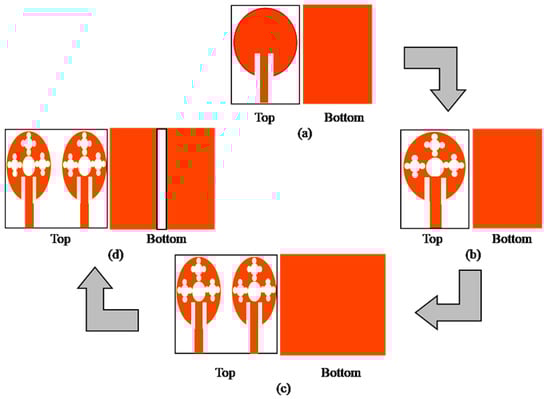
This section focuses on the design and description of the antenna that has been proposed. Figure 1 illustrates the schematic representation of the design procedure.
Figure 1.
Design process. (a) Conventional spherical patch antenna; (b) fractal spherical patch antenna; (c) MIMO antenna; (d) MIMO antenna with DGS.
The design process begins by initially developing a conventional single-element antenna in the form of a spherical patch. Subsequently, a fractal technique is applied to the patch, and the design is expanded to include a MIMO configuration consisting of two elements. The primary objective of this paper is the use of mm wave frequencies for 5G applications by establishing a MIMO antenna with a rectangular defection in the ground plane. The antenna is designed and simulated using HFSS 15.0 software. The antenna is 28.22 44 1.6 mm3 and has a simple construction. An economical FR4 substrate material is used to manufacture the antenna. The subsequent parts will cover the stepwise design process, optimization, and the accompanying results.
2.1. Single Antenna Design Evolution Steps
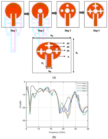
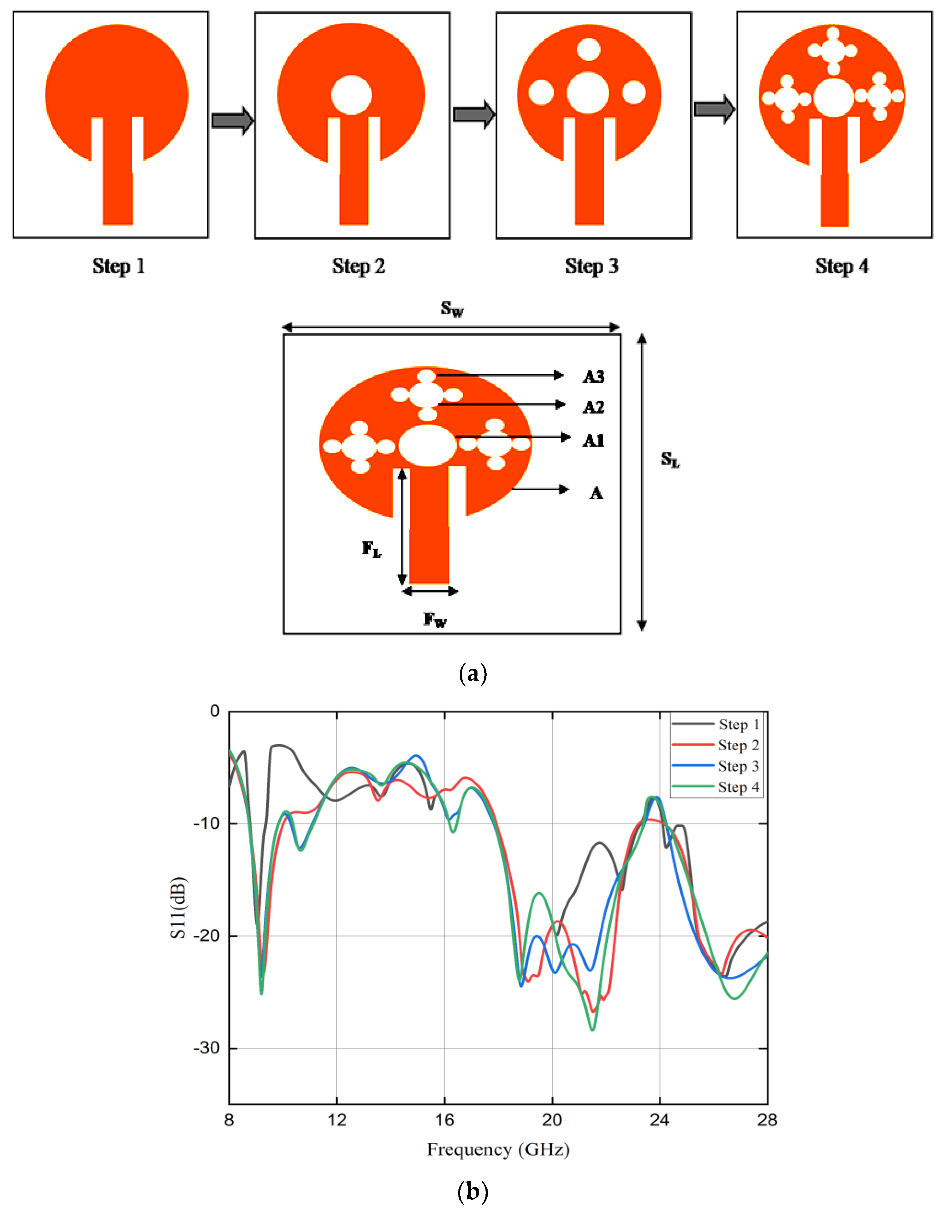
Figure 2a depicts a fractal structure used to design a sole antenna element. A spherical patch of radius A is utilized as the basis structure in step 1 (0th iteration), and its dimensions are determined using Equation (1).
where Vo is the free space speed of light; εr is the dielectric constant of material.
Figure 2.
(a) Basic element design evolution process. (b) Scattering parameters of single antenna.
Step 2 involves scaling the base structure by a factor of one-third (first iteration), resulting in 5 small circles with radius A1. One central circle is then taken out of the 5 small circles, leaving 4 circles in total. Iteration 2 (step 2) is achieved by repeating the previous iteration’s steps on the remaining 4 circles, which entails dividing the 4 circles once more into 5 small circles of radius (A2), removing one center circle from each of the 5 small circles, and leaving 16 circles in total. In the case of step 3 (iteration 3), the remaining 16 circles are then further divided into 5 smaller circles of radius (A3), and once again the one center circle is eliminated from each of the 5 smaller circles, leaving a total of 64 circles. Table 1 shows the method used to calculate the radiuses A1, A2, and A3. Due to fabrication limitations and the intricate structure, additional iterations are not possible.
Table 1.
Calculation of radius A1, A2 and A3.
Once the patch structure has been created, then, using Equation (2), the size of the microstrip feedline is determined. The suggested single antenna element’s dimensions are listed in Table 2.
Table 2.
Dimensions of single-element antenna.
The S-parameters are analyzed in order to understand more about the antenna’s performance. Figure 2b displays the single-antenna iteration stages and scattering parameter results and Table 3 displays the findings of various iteration studies regarding the effect of their findings. The graphic makes it abundantly evident that an increase in the number of iterations will result in an increase in both the bandwidth and the bands. For the 0th iteration, the proposed antenna employs a patch with a circular form as depicted in step 1 of Figure 2a. The circular geometry of the antenna facilitates the presence of numerous resonant modes, each associated with a distinct frequency band. In the context of the initial iteration, the antenna demonstrates resonance at three distinct frequencies, specifically 9 GHz, 18.8 GHz, and 26.4 GHz, as shown in Table 3. Furthermore, when a single slot (1st iteration) is applied to the patch, as depicted in step 2 of Figure 2a, the antenna exhibits resonance at three distinct multiband frequencies: 9.3 GHz, 21.7 GHz, and 26.2 GHz. The resonance behavior of the antenna changes due to slot loading on the surface of the radiating patch. This may be due to the possible changes in surface current distributions, as a result of which, the electric and magnetic field distribution alters leading to changes in the resonant behavior of the antenna with the generation of additional resonances. The additional resonances in conjunction with main resonance of the initial patch results in a broader bandwidth in comparison to the initial iteration. For the 2nd iteration, the resonance occurs at four different frequencies below a level of −10 dB S11. As a result, the iteration is carried out for the next step (iteration 3), which results in an antenna that resonates for five frequencies while increasing bandwidth. The conclusion that can be drawn from this is that the antenna configuration for the third iteration gives balanced outcomes in the form of resonating frequencies and bandwidth.
Table 3.
Iteration effect on single element antenna.
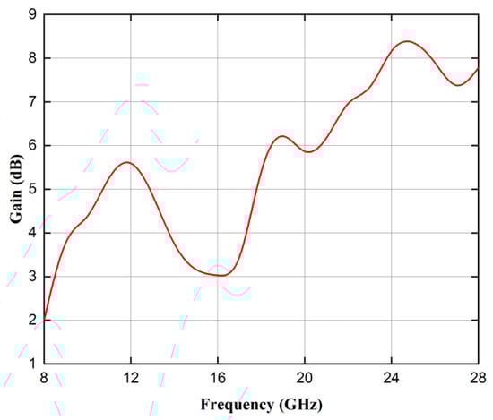
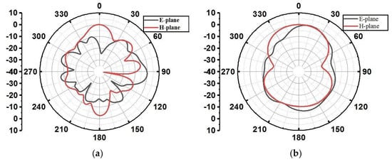
Figure 3 illustrates the gain of a single antenna. It is evident from the figure that the suggested antenna attains a maximum gain of 8.46 dB. Figure 4 illustrates the simulated E and H plane radiation patterns of the single element patch antenna operating at frequencies of 9.2 GHz, 21.5 GHz, and 26.7 GHz. The antenna exhibits partly omnidirectional radiation characteristics with multiple lobes at higher operating bands resonating at 21.5 GHz and 26.7 GHz.
Figure 3.
Gain of single antenna.
Figure 4.
Simulated E and H plane radiation patterns at (a) 9.2 GHz; (b) 21.5 GHz; (c) 26.7 GHz.
2.2. Two-Element MIMO Antenna Design
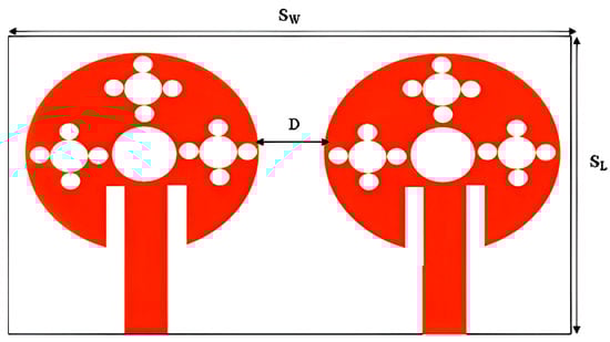
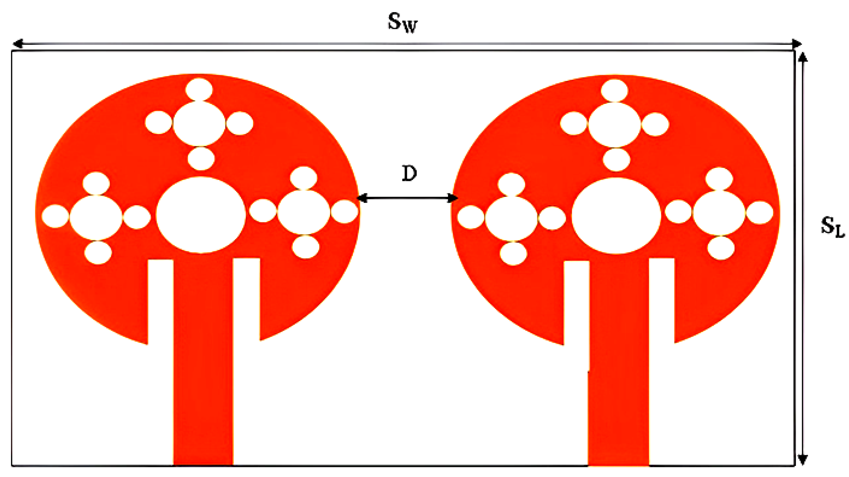
Figure 5 shows the modified two-port MIMO antenna with 44 28.22 mm2 substrate dimensions. In order to create a dual-port MIMO antenna, two separate investigations are undertaken with the objective of attaining optimal outcomes. Initially, the focus of the study is on optimizing the spacing between two antenna elements. Subsequently, the antenna is examined in three distinct orientations, labeled as I, II, and III.
Figure 5.
Two-port MIMO antenna.
2.2.1. Distance Optimization
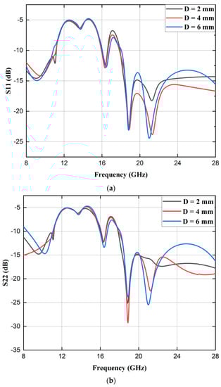
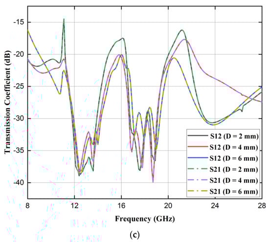
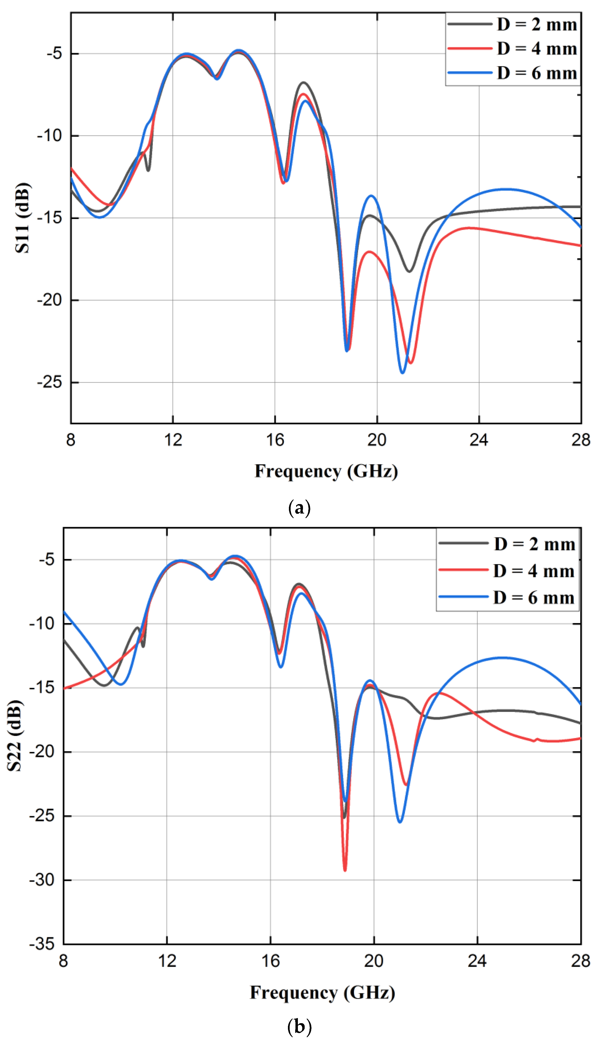
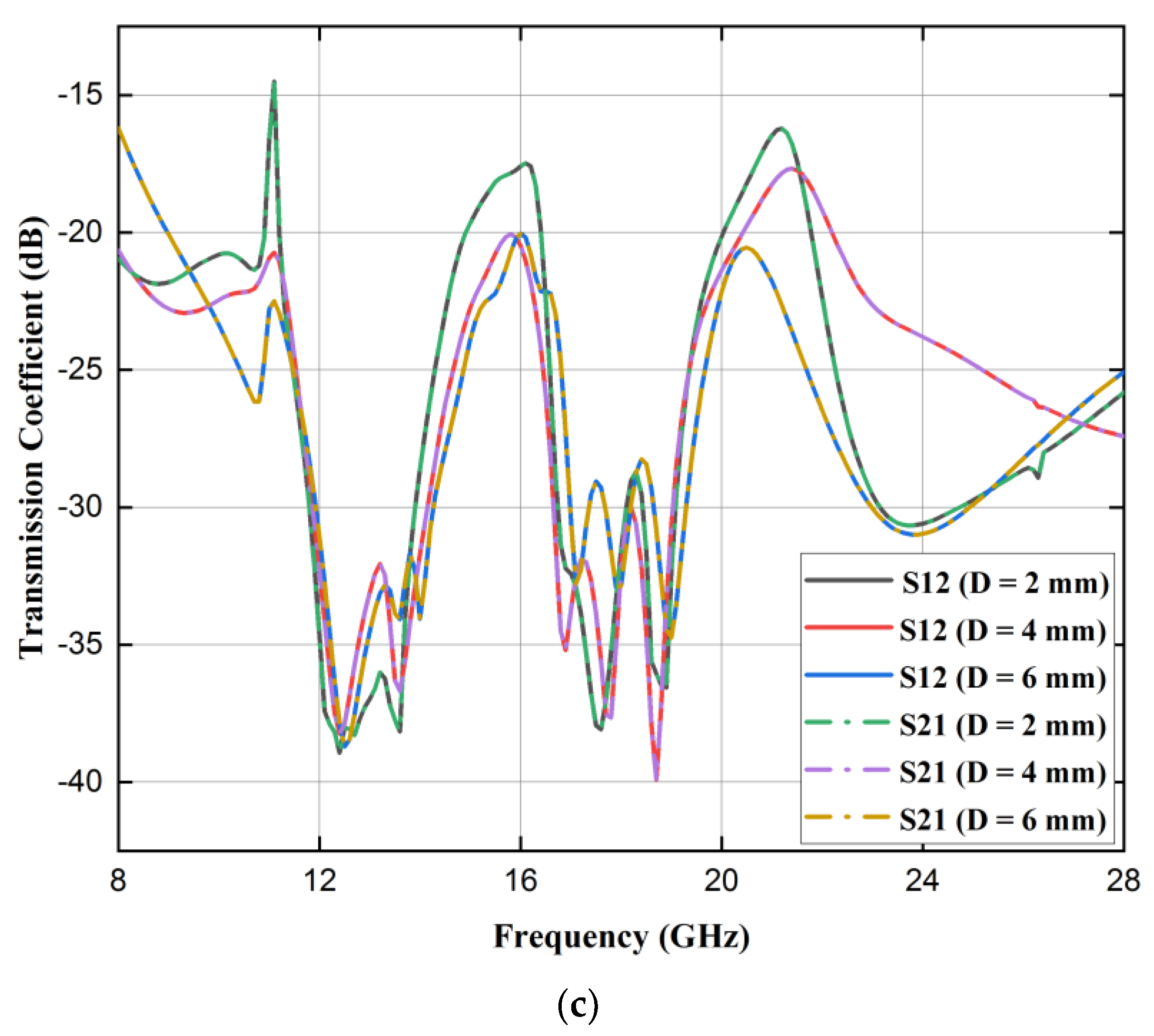
The two antennas are placed at distances of D = 2 mm, 4 mm, and 6 mm. The graphical depiction of the fluctuation in reflection coefficient and transmission coefficient can be observed in Figure 6a–c, while the summarized results are presented in Table 4. At a distance of 4 mm, the antenna exhibits resonance at frequencies of 9.7, 16.3, 18.8, and 21.4 GHz. These resonant frequencies are accompanied by increased bandwidths of 3100, 600, and 10,100 MHz, respectively, as compared to the bandwidth achieved at distances of 2 mm and 6 mm. The maximum level of isolation attained for a distance (D) of 4 mm is −40 dB. In comparison, for diameters of 2 mm and 6 mm, the maximum isolation levels are −38.9 dB and −38.6 dB, respectively. This shows that at D = 4 mm, the antenna provides better results.
Figure 6.
Distance variation, scattering parameters (in dB): (a) S11; (b) S22; (c) S12 and S21.
Table 4.
MIMO distance variation analysis.
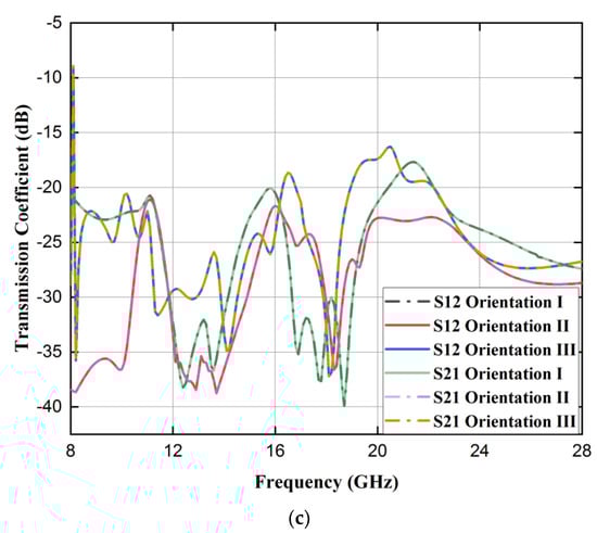
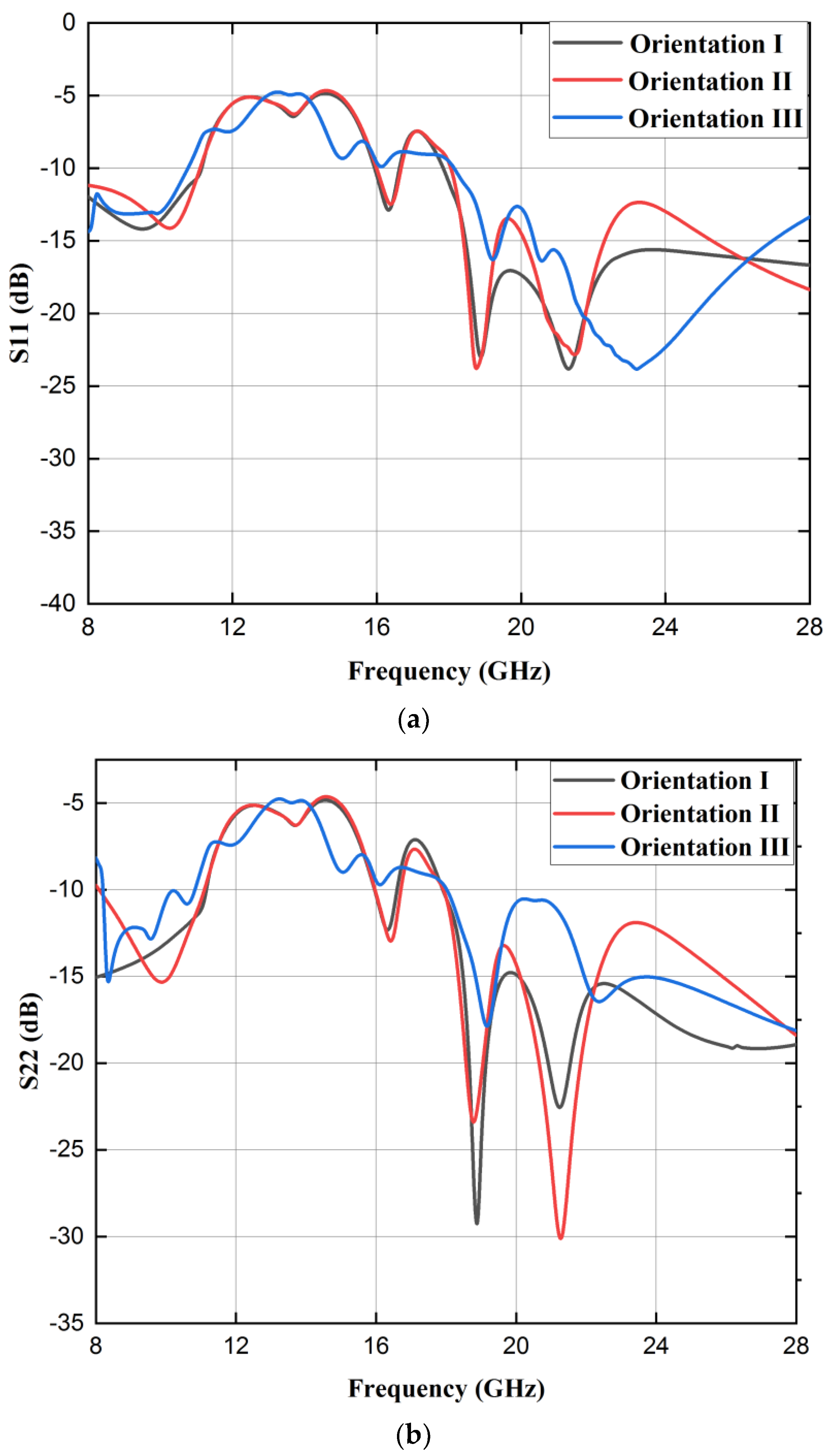
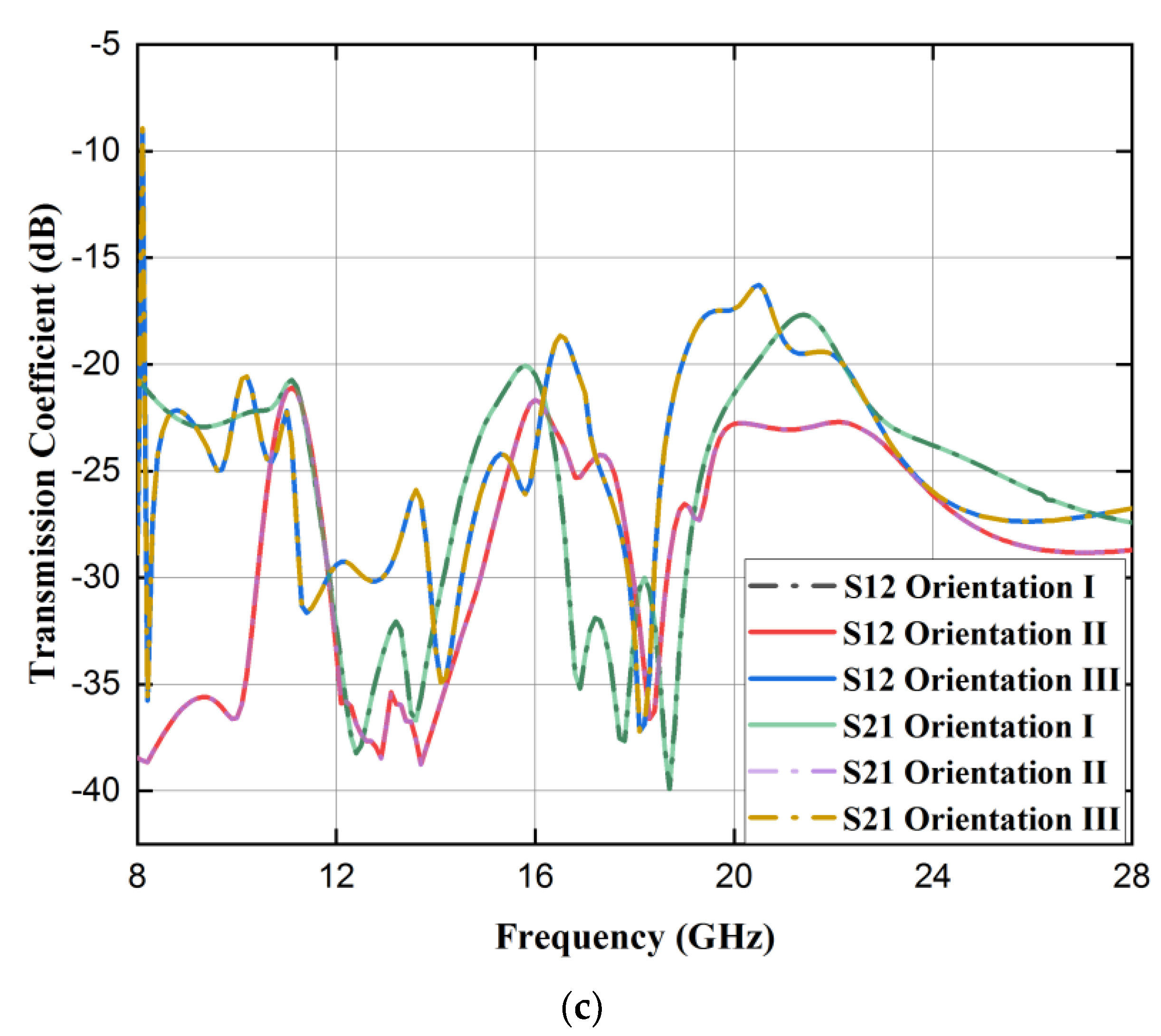
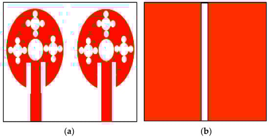
2.2.2. Analysis of Orientation
In a MIMO system, the orientation of antennas can significantly influence the isolation between them. The isolation between antennas is the degree to which their signals interfere with one another. Several decoupling mechanisms can result in varying degrees of isolation at various orientations. The proposed antenna employs the spatial diversity decoupling technique. Basically, spatial diversity is accomplished by using antennas that are physically separated. When these antennas are oriented differently, they sample distinct spatial signal paths, reducing the likelihood that fading or interference will simultaneously affect both antennas. In the case of orientation I, the two elements of the antenna are situated in close proximity to one another, with a specific separation distance of 4 mm, as depicted in Figure 7a. During this configuration, the antenna offers improved bandwidth and enhanced isolation. According to Figure 8a–c, the antenna resonates at frequencies of 9.7, 16.3, 18.8, and 21.4 GHz, with three bands encompassing the frequency ranges of 8 to 11.1 GHz, 16 to 16.5 GHz, and 17.9 to 28 GHz, with a maximum isolation of −40 dB.
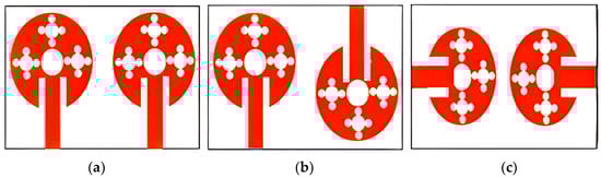
Figure 7.
MIMO antenna with different orientations: (a) I; (b) II; and (c) III.
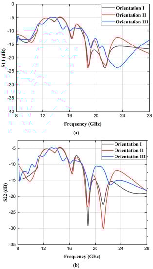
Figure 8.
Orientation analysis, scattering parameters (in dB): (a) S11; (b) S22; (c) S12 and S21.
As depicted in Figure 7b, the design of orientation II involves the inversion of antenna II position, while the position of antenna I remains intact. The antenna resonant frequencies and bandwidths in this particular orientation can be deduced from the data presented in Figure 8a–c. It is evident that the antenna resonates at frequencies of 10.3 GHz, 16.4 GHz, 18.8 GHz, and 21.5 GHz, with corresponding bandwidths of 3000 MHz, 600 MHz, and 9900 MHz. The maximum level of isolation attained is −38.74 decibels. As indicated in Figure 7c, both antennas are turned 90 degrees for orientation III. The antenna exhibits resonance at two specific frequencies, namely 8.2 and 19.2 GHz, with a maximum attainable isolation of −37.21 dB. Upon doing a comparative analysis of the outcomes from all three orientations, it is evident that orientation I exhibits superior performance in terms of bandwidth and isolation when compared to the other two orientations. Summarized results of all three orientations are presented in Table 5. Orientation I is commonly regarded as the most suitable design for a MIMO antenna.
Table 5.
MIMO orientation analysis.
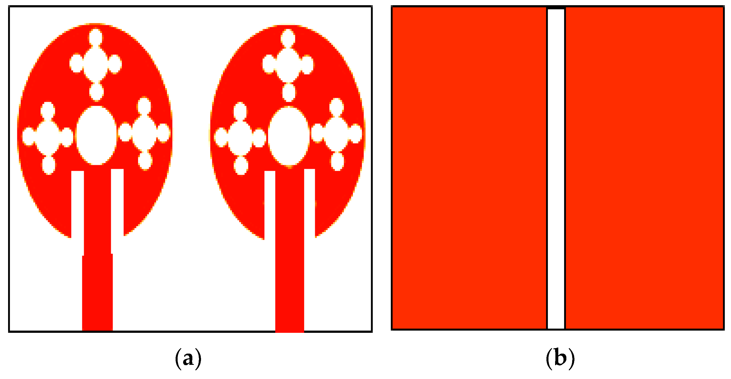
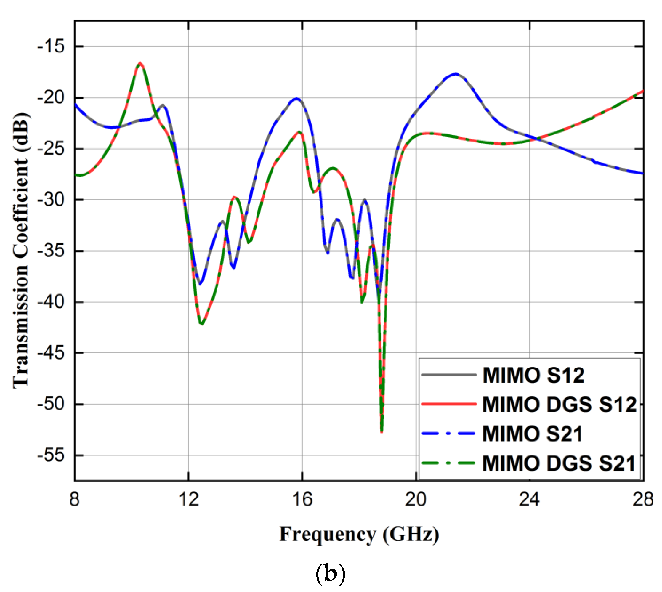
2.2.3. Analysis of MIMO Antenna with Defective Ground Structure
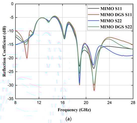
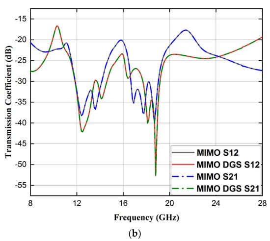
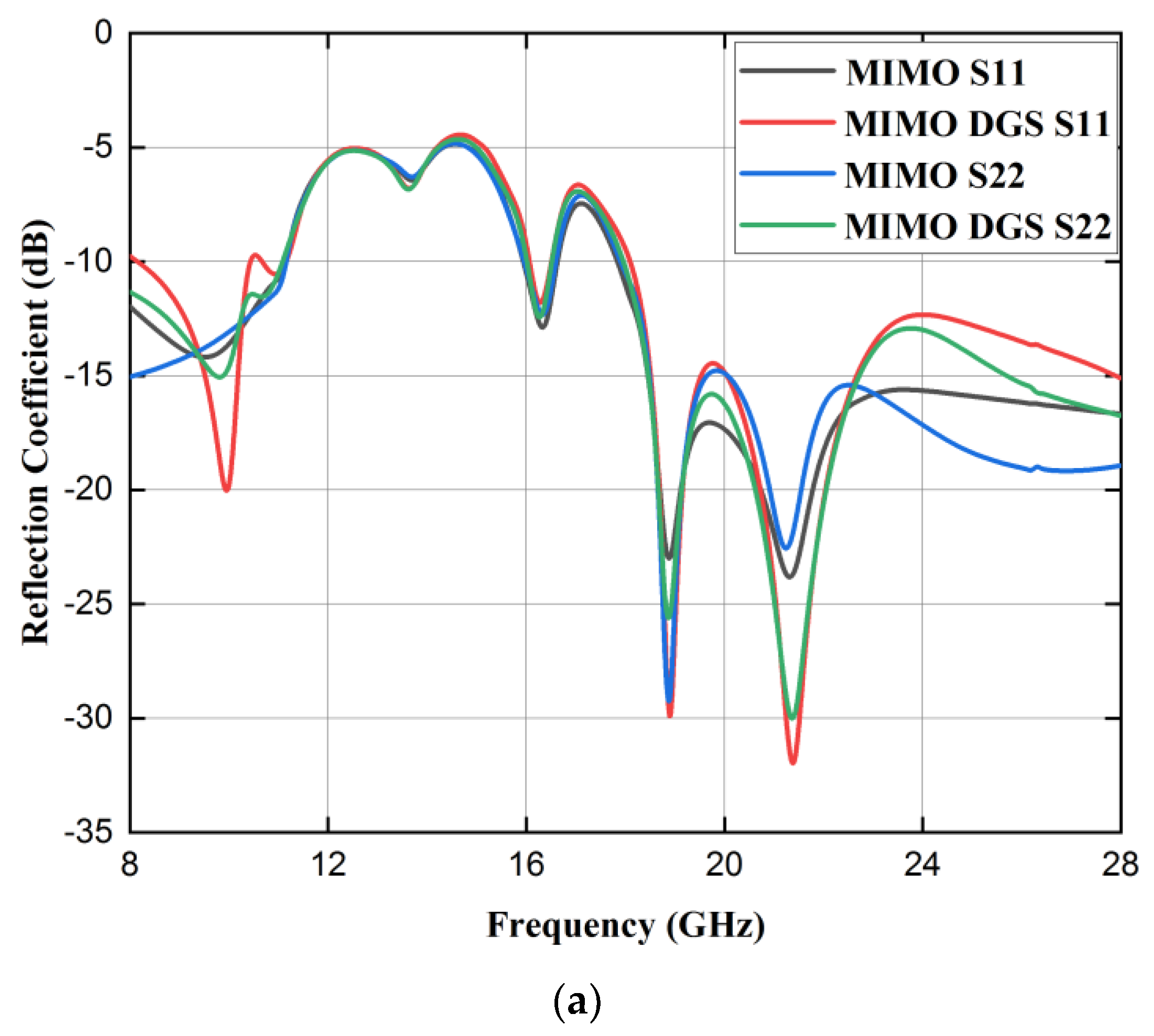
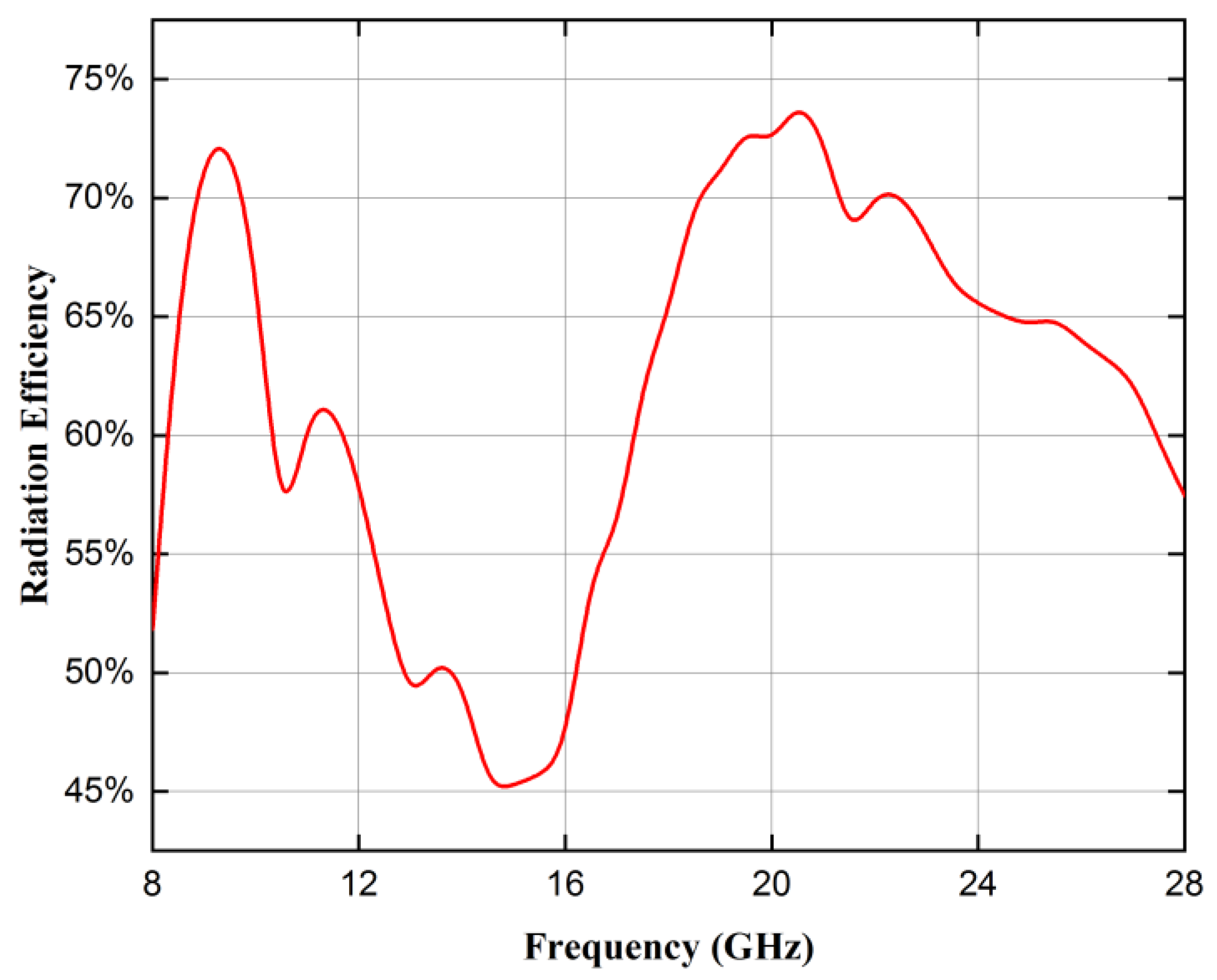
Defective ground construction is added to improve the isolation between the antennas. The DGS is utilized within the ground plane, which consists of a single vertical rectangular slot of 1 mm width, as depicted in Figure 9. The reflection coefficient parameters are plotted in Figure 10a. The near-field coupling effects between MIMO antennas are mitigated by the inclusion of a slot, as evidenced by the transmission coefficient curves depicted in Figure 10b. It is noteworthy that there is an enhancement in the maximum level of isolation, increasing from −40 dB to −52.72 dB within the antenna’s components. Consequently, deployment of the slot in ground plane resulted in an approximate 12 dB increase in isolation. Summarized results of MIMO and MIMO with DGS are presented in Table 6. Figure 11 illustrates the radiation efficiency of the proposed multiple input multiple output (MIMO) antenna. The first band, ranging from 8.2 to 10.4 GHz, exhibits a maximum radiation efficiency of 72%. In the second band, spanning from 16.1 to 16.5 GHz, the highest radiation efficiency reaches 55%. Lastly, the third band, covering the frequency range of 18.1 to 28 GHz, has a maximum radiation efficiency of 73%.
Figure 9.
MIMO with DGS: (a) Frontal view; (b) Lateral view.
Figure 10.
MIMO with DGS scattering parameters (dB): (a)S11 and S22; (b) S12 and S21.
Table 6.
MIMO and MIMO DGS analysis.
Figure 11.
Simulated radiation efficiency of the proposed MIMO antenna.
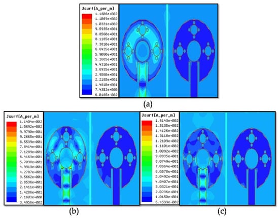
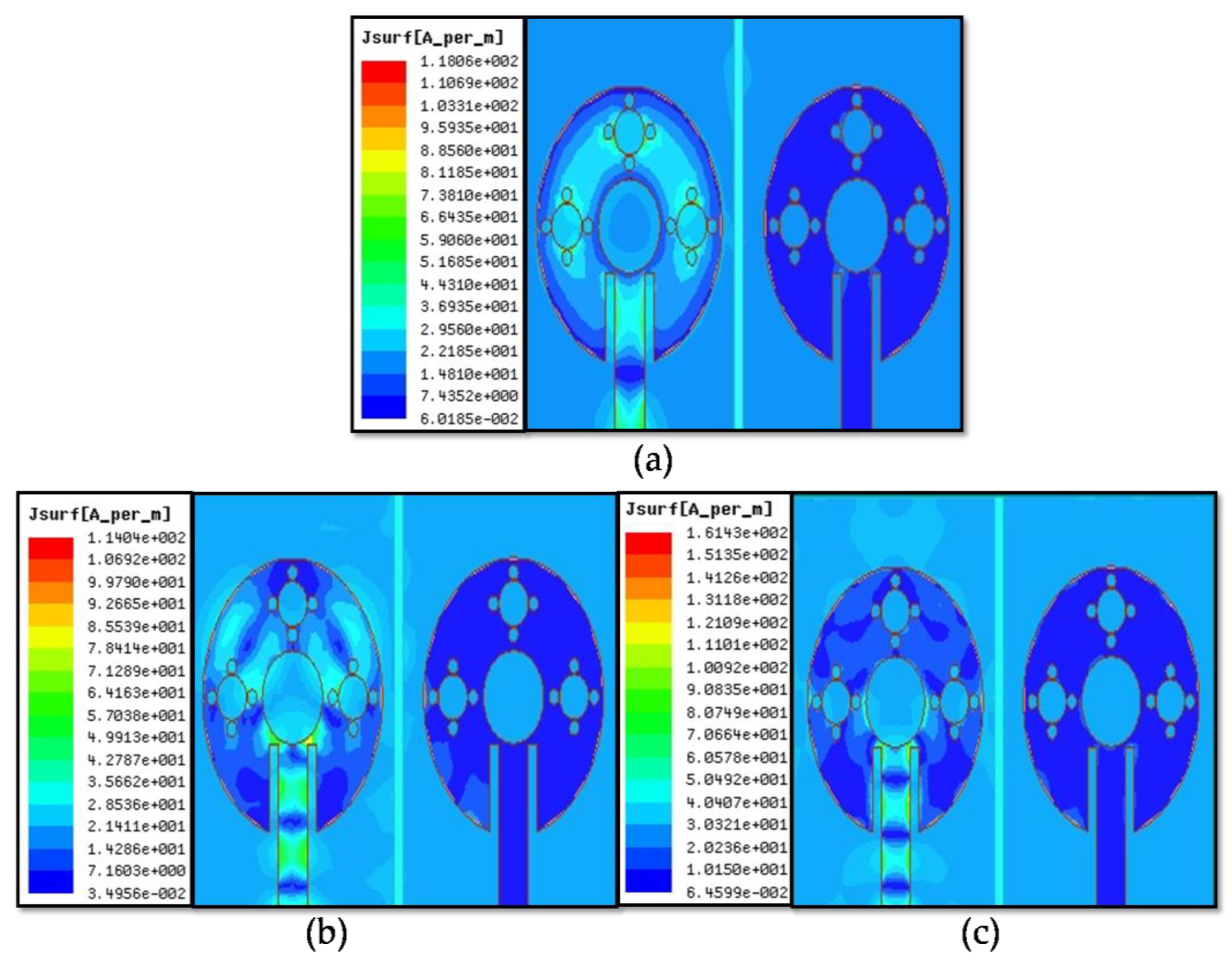
The effects of current distribution at 9.7 GHz, 18.8 GHz, and 21.4 GHz are shown in Figure 12. One port of the MIMO antenna must be excited while the other port is terminated so that the distribution of surface currents can be studied. Hence, port one is stimulated while port two of the proposed antenna is terminated. The observation may be made that in Figure 9, there is a prominent distribution of high current within the initial radiating patch via port 1. Conversely, the surface current near port 2 experiences a decrease. The observed phenomenon definitely signifies a decrease in the level of mutual coupling between two antennas.
Figure 12.
Distribution of surface current by exciting port 1 and discontinuing port 2 at (a) 9.7 GHz (b) 18.8 GHz, and (c) 21.4 GHz.
3. Results and Discussion
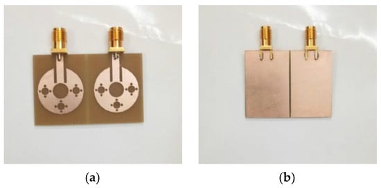
To ensure the credibility of the acquired outcomes, an antenna is fabricated on a substrate composed of FR4 material. The frontal and lateral perspectives of the constructed antenna are illustrated in Figure 13a and Figure 13b, respectively.
Figure 13.
Constructed MIMO with DGS: (a) Frontal and (b) lateral view.
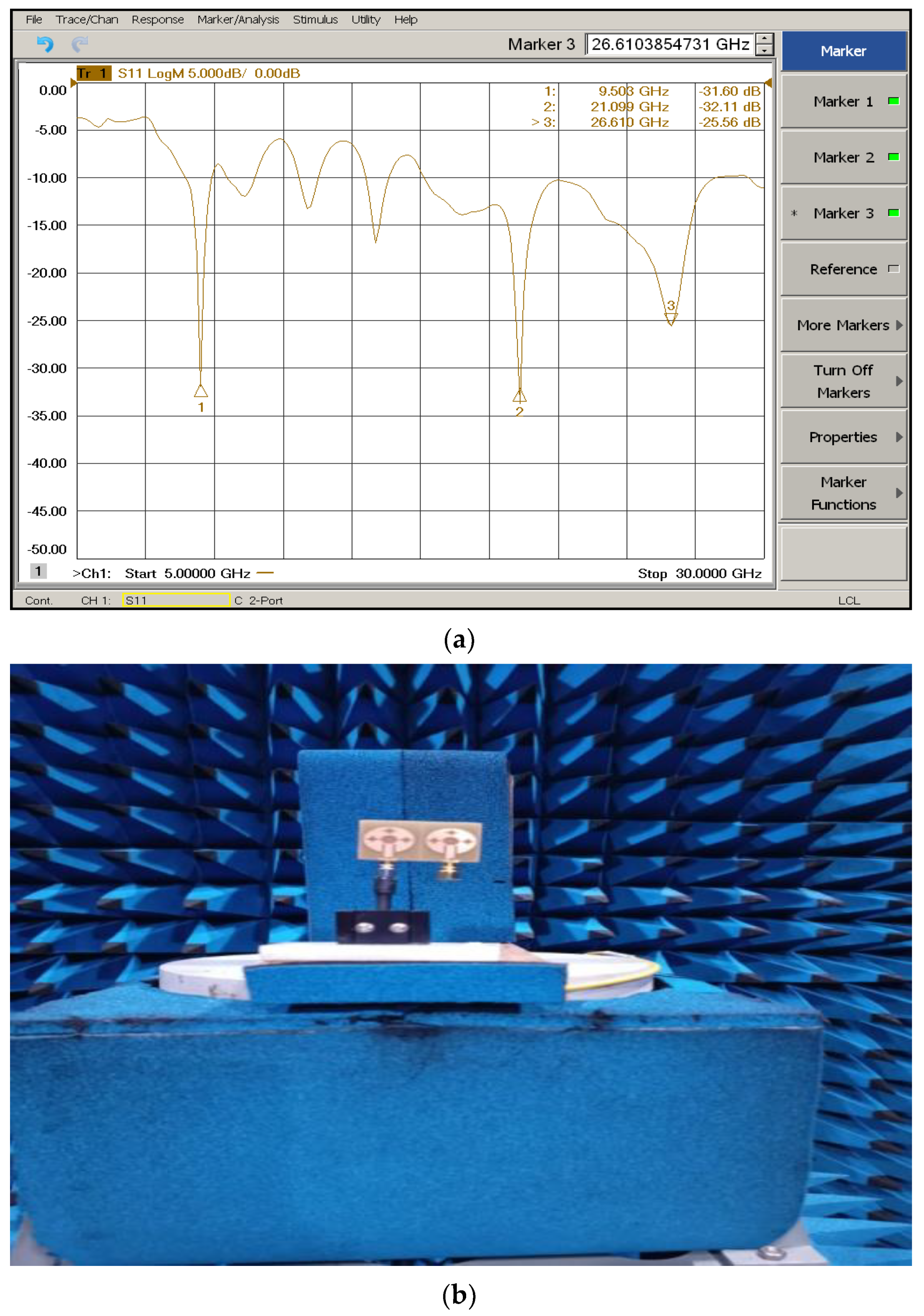
The fabrication procedure is carried out using the EP-42 Auto PCB prototype machine. Connectors are used to attach the designed antenna to the ZNB- 40 VNA in order to determine its transmission and reflection coefficients. The measured results snapshot taken from VNA is displayed in Figure 14a. The suggested antenna’s radiation pattern is measured in an anechoic room utilizing a reference horn antenna as the transmitter, as seen in Figure 14b.
Figure 14.
Experimental setup. (a) Measurement of reflection coefficient S11 dB; (b) measurement of radiation pattern.
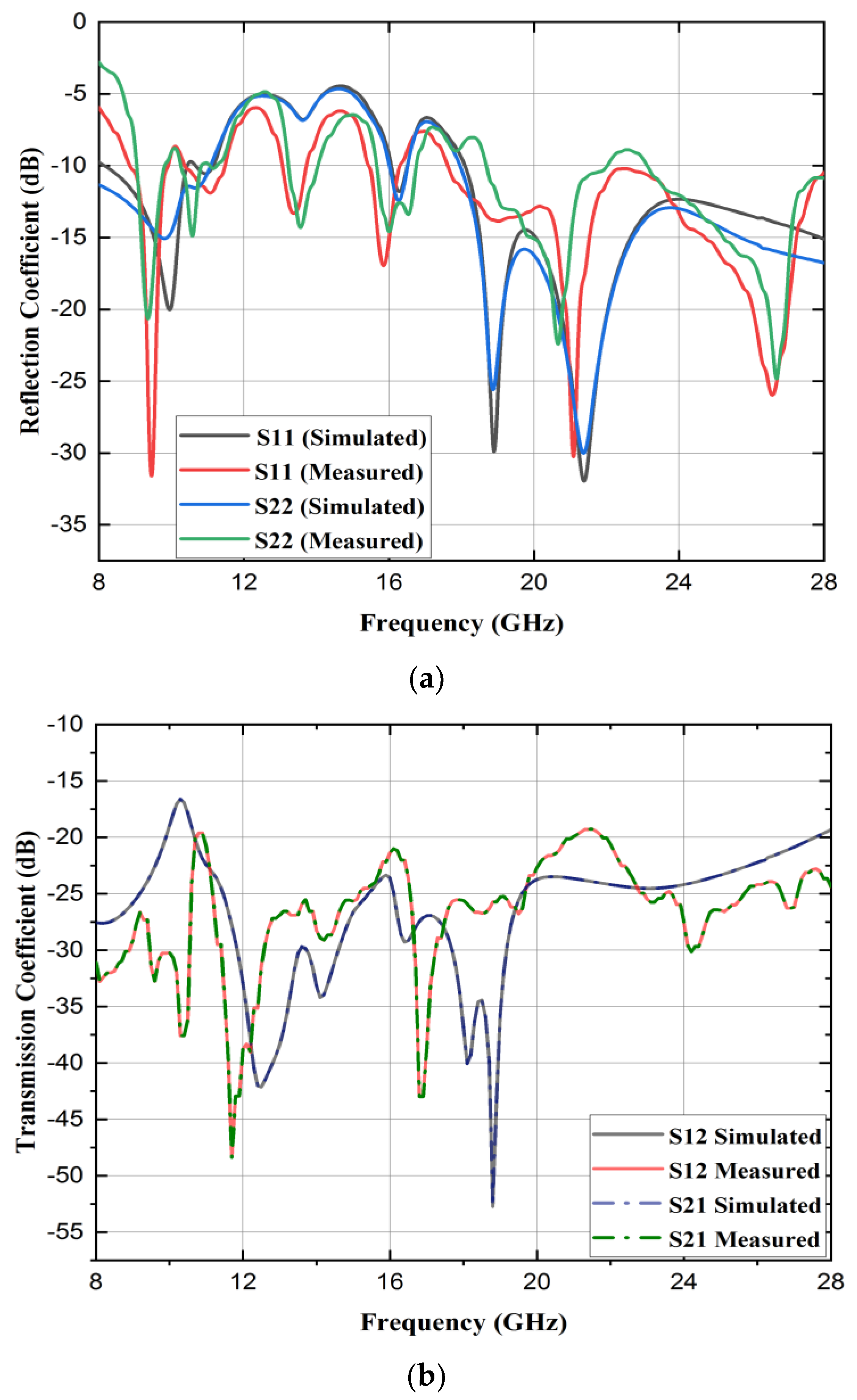
Figure 15a,b display the reflection and transmission coefficients, both measured and simulated. The antenna under consideration exhibits resonances at frequencies of 9.5 GHz, 11.1 GHz, 13.4 GHz, 15.8 GHz, 21.1 GHz, and 26.6 GHz, accompanied by corresponding S11 (dB) of −32.15, −11.95, −13.3, −17.0, −33.2, and −26.14, respectively. These resonances cover the frequency bands of 8.9–9.9 GHz, 10.4–11.4 GHz, 13.1–13.7 GHz, 15.4–16.2 GHz, and 17.7–28 GHz. Furthermore, the antenna demonstrates enhanced impedance bandwidths of 1000 MHz, 1000 MHz, 600 MHz, 800 MHz, and 10,300 MHz, respectively, within these frequency ranges. The maximum isolation between the two antennas is −48.37 dB. In the case of simulated findings, the antenna exhibits resonance at 9.7, 16.3, 18.8, and 21.4 GHz, accompanied by reflection coefficients of −20.04 dB, −12 dB, −31.9 dB, and −32.3 dB, respectively. The frequency ranges for the covering bands in the simulation are as follows: 8.2–10.4 GHz, 16.1–16.5 GHz, and 18.1–28 GHz. The corresponding impedance bandwidths for these bands are 2200 MHz, 400 MHz, and 9900 MHz, respectively. The simulation results demonstrate a maximum isolation of −52.72 dB. The observed discrepancies in resonant frequencies, as determined by measurements and simulations, might be attributed to several factors, including manufacturing imperfections, the SMA connectors, and disparities between the actual substrate and its modeled counterpart.
Figure 15.
Measure and simulated scattering parameters (dB): (a) S11 and S22; (b) S12 and S21.
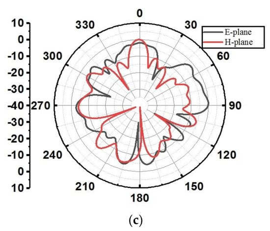
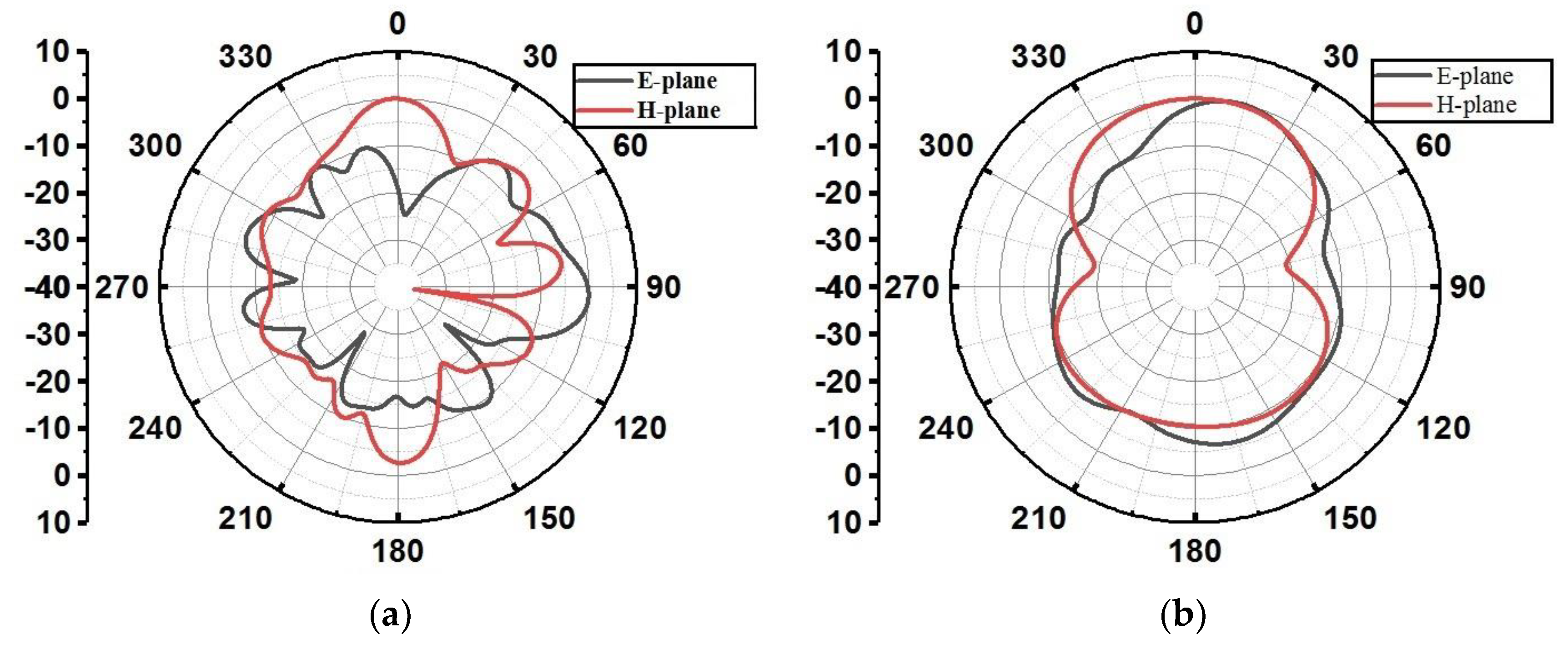
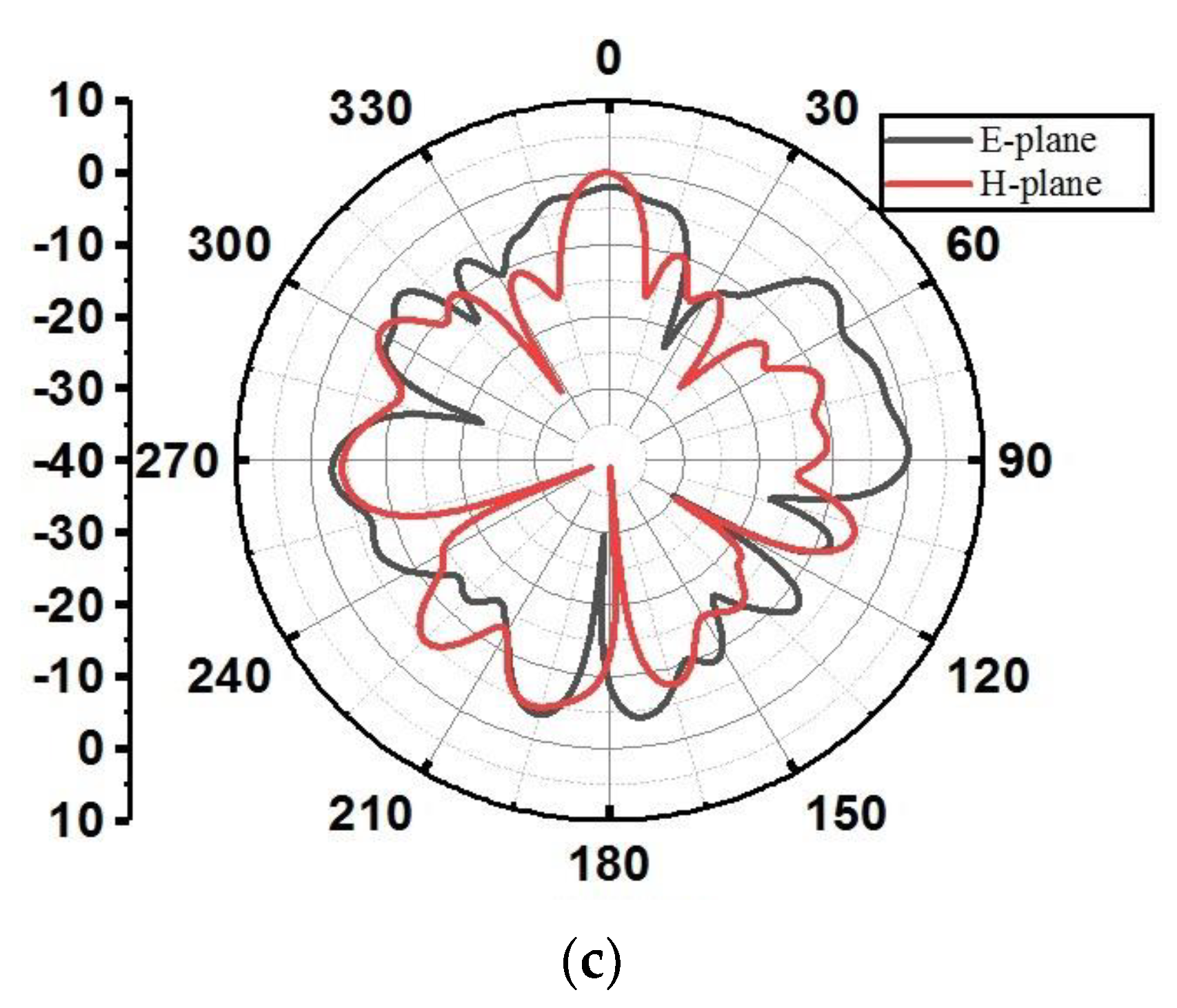
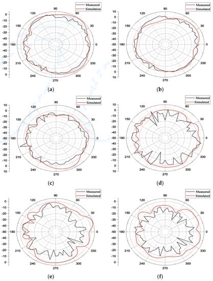
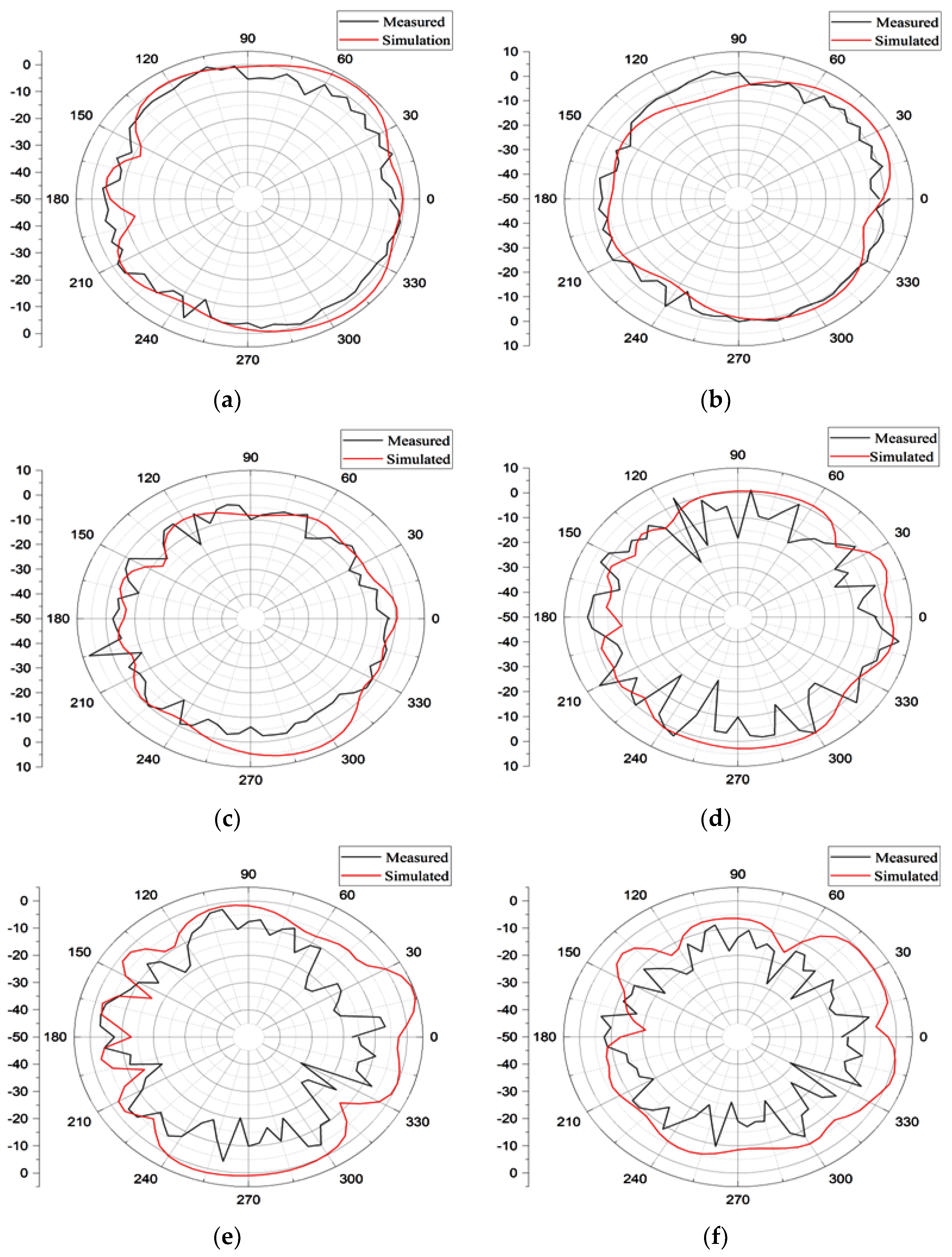
Figure 16 displays the radiation pattern in the vertical (E) and horizontal (H) fields planes at frequencies of 9.5, 21.1, and 26.6 GHz, as both simulated and measured. The E plane is also known as the XZ plane with a phi angle of 0 degrees, and the YZ plane with a phi angle of 90 degrees is known as horizontal plane. The antenna under consideration demonstrates a virtually omnidirectional radiation pattern at a lower resonant frequency of 9.5 GHz. However, at higher resonant frequencies of 21.1 GHz and 26.6 GHz, lobes are observed in both the horizontal (H) and vertical (E) planes. The presence of multi-reflection in the measuring environment may lead to observed differences and inconsistencies between the reported measured outcomes and simulated outcomes. Overall, the suggested antenna has a consistently stable pattern.
Figure 16.
Radiation pattern simulation and measurement: (a) (E plane) 9.5 GHz, (b) (H Plane) 9.5 GHz, (c) (E plane) 21.1 GHz, (d) (H Plane) 21.1 GHz, (e) (E plane) 26.6 GHz, (f) (H Plane) 26.6 GHz.
3.1. Analysis of Diversity Performance
Multiple parameters, such as the envelope correlation coefficient, the diversity gain, and the mean effective gain, are used to assess the efficacy of the proposed MIMO antenna.
3.1.1. Envelope Correlation Coefficient
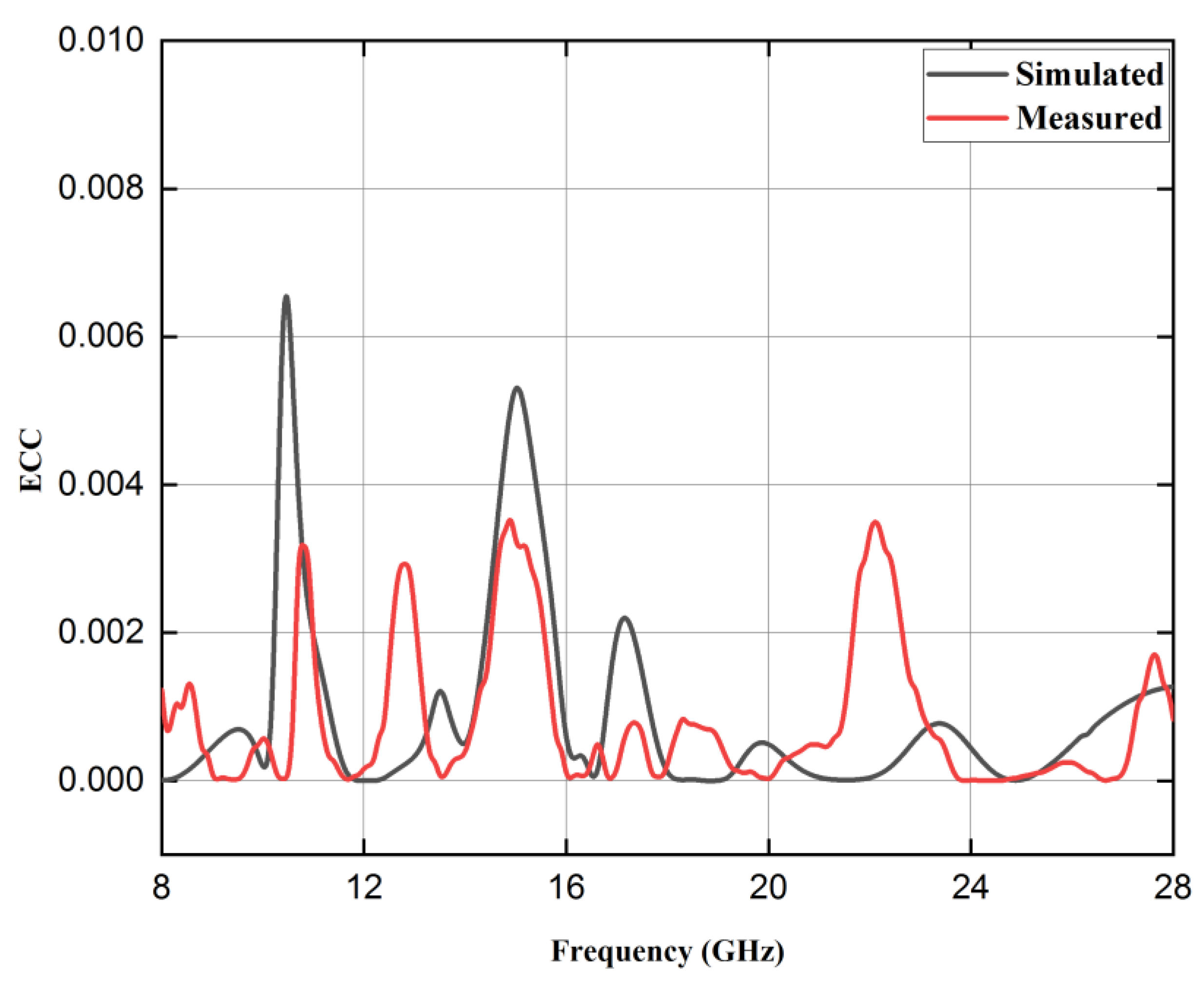
The evaluation of the ECC serves as a crucial metric for quantifying the degree of isolation achieved between the different elements of the antenna system. One of these two methods mentioned below can be utilized in order to carry out the computation of ECC based on the parameters of the antenna. The initial approach entails employing the far field emission patterns of the antenna components [23]. The second method, which is comparatively less difficult and requires fewer computational resources, involves employing S parameters [9]. The second methodology is commonly employed for high-efficiency MIMO antennas, making the method based on S parameters the favored choice. The acceptable threshold for the value of ECC should be below the 0.05 level. Equation (3) utilizes S-parameter methodologies for MIMO systems consisting of two elements [9]. Figure 17 illustrates the simulations and measurable curves associated with the MIMO antenna system that is given in this research. The antenna’s ECC consistently remains below 0.05 across its entire operational bandwidth.
Figure 17.
Simulated and measured ECC curve.
3.1.2. Diversity Gain
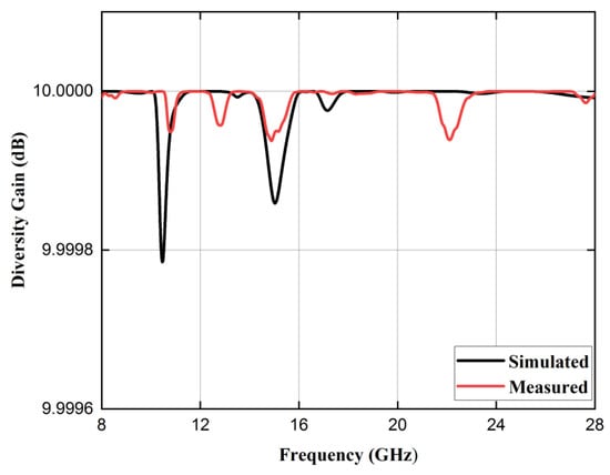
The usefulness of diversity can be measured by an indicator called diversity gain, which is calculated using Equation (4) [24]. At a significance level of 1% and employing maximal ratio combining, the attainment of a diversity gain of 10 represents the maximum level. In order to ensure practical applicability, it is recommended that the parameter DG exceed a value of 9.99 dB. Throughout the entire range of operational frequencies, as shown in Figure 18, the diversity gain (DG) of this antenna remains within the permitted limit.
Figure 18.
Simulated and measured diversity gain (DG) curve.
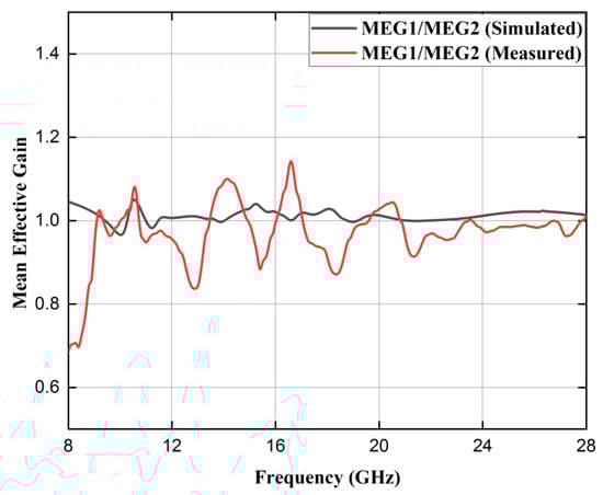
3.1.3. Mean Effective Gain
The measurement of the power received by the diversity antenna in relation to the power received by an isotropic antenna in a fading environment is known as MEG (Mean effective gain) [30]. Equation (5) is used for carrying out the calculation, and the corresponding graph is presented in Figure 19.
where i designates the particular antenna under consideration and k specifies the total number of antennas. In this particular scenario, the value of k corresponds to 2 for the two-port antenna. Consequently, we have
Figure 19.
Simulated and measured mean effective gain curve.
According to reference [31], the ratio of MEG1/MEG2 for the suggested two-port element antenna should be less than 3 dB in order to obtain excellent diversity performance. The validation of the MEG readings being less than 1.2 dB can be observed from Figure 16. The performance data for the suggested antenna are shown in Table 7. The outcomes indicate that the antenna exhibits favorable diversity properties, making it highly suitable for millimeter wave applications.
Table 7.
MIMO diversity performance.
4. Comparison with Prior Research Works
Table 8 presents a comprehensive comparison between the proposed multiple input multiple output (MIMO) antenna and previous studies in terms of bandwidth, bands, isolation, envelope correction coefficient (ECC), and diversity gain.
Table 8.
MIMO antenna comparison with other prior work.
According to the data shown in Table 8, it can be observed that the proposed antenna demonstrates the ability to operate over many frequency bands, while also improving the bandwidth with commendable envelope correction coefficient (ECC) and diversity gain. While the findings of [9] demonstrate similar characteristics with slightly higher bandwidth, the MIMO antenna proposed in this study exhibits lower ECC and greater value in terms of multiband features compared to the structure described in the literature [9]. The antenna under consideration in this study offers enhanced system capacity and MIMO performance compared to the antenna configuration described in [9].
5. Conclusions
The present work provides a description of a low-profile two-port MIMO antenna constructed using DGS. The paper introduces an antenna consisting of a single element. The integration of a single antenna into a two-port multiple input multiple output (MIMO) configuration enhances its performance, and a comprehensive analysis of its performance characteristics is conducted. A rectangular defect in the ground plane is also integrated into it to increase the antenna’s performance. As a result, 8.37 dB improvement in the isolation between the two antenna elements is achieved. When compared to comparable research documented in the existing body of literature, the MIMO DGS antenna under evaluation stands out due to its wide bandwidth, good isolation, minimum ECC, compact design, and cost-effectiveness. As a result, this antenna design demonstrates promising characteristics that make it a feasible option for use in the millimeter-wave 5G range’s n258 band, X band, and Ku band.
Author Contributions
Conceptualization, N.B., P.K.M. and S.D.; methodology, N.B., T.I. and S.A.; software, N.B., S.D. and P.K.M.; validation, M.A. and T.I.; formal analysis, N.B., S.D. and S.A.; investigation, T.I. and S.A.; resources, M.A.; data curation, N.B., P.K.M. and S.A.; writing—original draft preparation, N.B., S.D. and P.K.M.; writing—review and editing, T.I., M.A. and S.A.; visualization, S.D., P.K.M. and T.I.; supervision, P.K.M. and S.D.; project administration, M.A.; funding acquisition, M.A. All authors have read and agreed to the published version of the manuscript.
Funding
The Deputyship for Research and Innovation, Ministry of Education, Saudi Arabia (Grant Number: IFKSUOR3–315-3).
Data Availability Statement
The data presented in this research are available on request from the corresponding author.
Acknowledgments
The authors extend their appreciation to the Deputyship for Research & Innovation, Ministry of Education in Saudi Arabia for funding this research work through the project no. (IFKSUOR3–315-3).
Conflicts of Interest
The authors declare no conflict of interest.
References
- Benkhadda, O.; Saih, M.; Ahmad, S.; Al-Gburi, A.J.A.; Zakaria, Z.; Chaji, K.; Reha, A. A Miniaturized Tri-Wideband Sierpinski Hexagonal-Shaped Fractal Antenna for Wireless Communication Applications. Fractal Fract. 2023, 7, 115. [Google Scholar] [CrossRef]
- Vallappil, A.K.; Khawaja, B.A.; Rahim, M.K.A.; Uzair, M.; Jamil, M.; Awais, Q. Minkowski–Sierpinski Fractal Structure-Inspired 2 × 2 Antenna Array for Use in Next-Generation Wireless Systems. Fractal Fract. 2023, 7, 158. [Google Scholar] [CrossRef]
- Singh, A.K.; Dwivedi, A.K.; Jha, C.; Singh, S.; Singh, V.; Yadav, R.S. A Compact MIMO Antenna for 5G NR Frequency Bands N257/N258/N261 Under Millimeter-Wave Communication. IETE J. Res. 2022. [Google Scholar] [CrossRef]
- Kumar, S.; Dixit, A.S.; Malekar, R.R.; Raut, H.D.; Shevada, L.K. Fifth Generation Antennas: A Comprehensive Review of Design and Performance Enhancement Techniques. IEEE Access 2020, 8, 163568–163593. [Google Scholar] [CrossRef]
- Hong, W.; Baek, K.H.; Ko, S. Millimeter-Wave 5G Antennas for Smartphones: Overview and Experimental Demonstration. IEEE Trans. Antennas Propag. 2017, 65, 6250–6261. [Google Scholar] [CrossRef]
- Bilal, M.; Naqvi, S.I.; Hussain, N.; Amin, Y.; Kim, N. High-Isolation MIMO Antenna for 5G Millimeter-Wave Communication Systems. Electronics 2022, 11, 962. [Google Scholar] [CrossRef]
- Fatah, S.Y.A.; Hamad, E.K.I.; Swelam, W.; Allam, A.M.M.A.; Mohamed, H.A. Design of Compact 4-Port Mimo Antenna Based on Minkowski Fractal Shape Dgs for 5g Applications. Prog. Electromagn. Res. C 2021, 113, 123–136. [Google Scholar] [CrossRef]
- Abdelaziz, A.; Hamad, E.K.I. Isolation Enhancement of 5G Multiple-Input Multiple-Output Microstrip Patch Antenna Using Metamaterials and the Theory of Characteristic Modes. Int. J. RF Microw. Comput. Eng. 2020, 30, e22416. [Google Scholar] [CrossRef]
- Kumar, N.; Khanna, R. A Two Element MIMO Antenna for Sub-6 GHz and MmWave 5G Systems Using Characteristics Mode Analysis. Microw. Opt. Technol. Lett. 2021, 63, 587–595. [Google Scholar] [CrossRef]
- Kumar, N.; Khanna, R. A Compact Multi-Band Multi-Input Multi-Output Antenna for 4G/5G and IoT Devices Using Theory of Characteristic Modes. Int. J. RF Microw. Comput. Eng. 2020, 30, e22012. [Google Scholar] [CrossRef]
- Dkiouak, A.; Zakriti, A.; El Ouahabi, M. Design of a Compact Dual-Band MIMO Antenna with High Isolation for WLAN and X-Band Satellite by Using Orthogonal Polarization. J. Electromagn. Waves Appl. 2020, 34, 1254–1267. [Google Scholar] [CrossRef]
- Kumar, A.; Ansari, A.Q.; Kanaujia, B.K.; Kishor, J.; Kumar, S. An Ultra-Compact Two-Port UWB-MIMO Antenna with Dual Band-Notched Characteristics. AEU Int. J. Electron. Commun. 2020, 114, 152997. [Google Scholar] [CrossRef]
- Marzouk, H.M.; Ahmed, M.I.; Shaalan, A.A. Novel Dual-Band 28/38 GHz MIMO Antennas for 5g Mobile Applications. Prog. Electromagn. Res. C 2019, 93, 103–117. [Google Scholar] [CrossRef]
- Singh, A.K.; Mahto, S.K.; Sinha, R. A Miniaturized MIMO Antenna for C, X, and Ku Band Applications. Prog. Electromagn. Res. C 2021, 117, 31–40. [Google Scholar] [CrossRef]
- Hussain, N.; Awan, W.A.; Ali, W.; Naqvi, S.I.; Zaidi, A.; Le, T.T. Compact Wideband Patch Antenna and Its MIMO Configuration for 28 GHz Applications. AEU Int. J. Electron. Commun. 2021, 132, 153612. [Google Scholar] [CrossRef]
- Khan, M.K.; Feng, Q.; Zheng, Z. Experimental Investigation and Design of Uwb Mimo Antenna with Enhanced Isolation. Prog. Electromagn. Res. C 2021, 107, 287–297. [Google Scholar] [CrossRef]
- Sabek, A.R.; Ali, W.A.E.; Ibrahim, A.A. Minimally Coupled Two-Element MIMO Antenna with Dual Band (28/38 GHz) for 5G Wireless Communications. J. Infrared Millim. Terahertz Waves 2022, 43, 335–348. [Google Scholar] [CrossRef]
- Sehrai, D.A.; Asif, M.; Khan, J.; Abdullah, M.; Shah, W.A.; Alotaibi, S.; Ullah, N. A High-Gain and Wideband MIMO Antenna for 5G Mm-Wave-Based IoT Communication Networks. Appl. Sci. 2022, 12, 9530. [Google Scholar] [CrossRef]
- Ullah, H.; Rahman, S.U.; Cao, Q.; Khan, I.; Ullah, H. Design of SWB MIMO Antenna with Extremely Wideband Isolation. Electronics 2020, 9, 194. [Google Scholar] [CrossRef]
- Jabeen, S.; Khan, Q.U. An Integrated MIMO Antenna Design for Sub-6 GHz & Millimeter-Wave Applications with High Isolation. AEU Int. J. Electron. Commun. 2022, 153, 154247. [Google Scholar] [CrossRef]
- El-Hassan, M.A.; Farahat, A.E.; Hussein, K.F.A. Quad-Band MIMO Antenna System for 5G Mobile Handsets. Appl. Comput. Electromagn. Soc. J. 2021, 36, 1418–1428. [Google Scholar] [CrossRef]
- Sharawi, M.S.; Podilchak, S.K.; Hussain, M.T.; Antar, Y.M.M. Dielectric Resonator Based MIMO Antenna System Enabling Millimetre-Wave Mobile Devices. IET Microw. Antennas Propag. 2017, 11, 287–293. [Google Scholar] [CrossRef]
- Naga Jyothi Sree, G.; Nelaturi, S. Design and Experimental Verification of Fractal Based MIMO Antenna for Lower Sub 6-GHz 5G Applications. AEU Int. J. Electron. Commun. 2021, 137, 153797. [Google Scholar] [CrossRef]
- Gurjar, R.; Upadhyay, D.K.; Kanaujia, B.K.; Kumar, A. A Compact Modified Sierpinski Carpet Fractal UWB MIMO Antenna with Square-Shaped Funnel-like Ground Stub. AEU Int. J. Electron. Commun. 2020, 117, 153126. [Google Scholar] [CrossRef]
- Sharma, R.; Khanna, R. Geetanjali Compact Sub-6 GHz and MmWave 5G Wideband 2 × 1 MIMO Antenna with High Isolation Using Parasitically Placed Double Negative (DNG) Isolator. Wirel. Pers. Commun. 2022, 122, 2839–2857. [Google Scholar] [CrossRef]
- Al-Bawri, S.S.; Islam, M.T.; Shabbir, T.; Muhammad, G.; Shabiul Islam, M.D.; Wong, H.Y. Hexagonal Shaped near Zero Index (NZI) Metamaterial Based MIMO Antenna for Millimeter-Wave Application. IEEE Access 2020, 8, 181003–181013. [Google Scholar] [CrossRef]
- Abdullah, M.; Li, Q.; Xue, W.; Peng, G.; He, Y.; Chen, X. Isolation Enhancement of MIMO Antennas Using Shorting Pins. J. Electromagn. Waves Appl. 2019, 33, 1249–1263. [Google Scholar] [CrossRef]
- Ali, A.; Munir, M.E.; Marey, M.; Mostafa, H.; Zakaria, Z.; Al-Gburi, A.J.A.; Bhatti, F.A. A Compact MIMO Multiband Antenna for 5G/WLAN/WIFI-6 Devices. Micromachines 2023, 14, 1153. [Google Scholar] [CrossRef]
- Hassan Ghadeer, S.; Kamal Abd Rahim, S.; Alibakhshikenari, M.; Virdee, B.S.; Elwi, T.A.; Iqbal, A.; Al-Hasan, M. An Innovative Fractal Monopole MIMO Antenna for Modern 5G Applications. AEU Int. J. Electron. Commun. 2023, 159, 154480. [Google Scholar] [CrossRef]
- Kumari, T.; Das, G.; Sharma, A.; Gangwar, R.K. Design Approach for Dual Element Hybrid MIMO Antenna Arrangement for Wideband Applications. Int. J. RF Microw. Comput. Eng. 2019, 29, 1–10. [Google Scholar] [CrossRef]
- Naik, M.N.; Virani, H.G. A Compact Four Port MIMO Antenna for Millimeterwave Applications. Bull. Electr. Eng. Inform. 2022, 11, 878–885. [Google Scholar] [CrossRef]


Disclaimer/Publisher’s Note: The statements, opinions and data contained in all publications are solely those of the individual author(s) and contributor(s) and not of MDPI and/or the editor(s). MDPI and/or the editor(s) disclaim responsibility for any injury to people or property resulting from any ideas, methods, instructions or products referred to in the content. |
© 2023 by the authors. Licensee MDPI, Basel, Switzerland. This article is an open access article distributed under the terms and conditions of the Creative Commons Attribution (CC BY) license (https://creativecommons.org/licenses/by/4.0/).