Article

Design and Modelling of a Compact Triband Passband Filter for GPS, WiMAX, and Satellite Applications with Multiple Transmission Zero’s

1
School of Information Science and Engineering, NingboTech University, Ningbo 315100, China
2
College of Information Science and Electronic Engineering, Zhejiang University, Hangzhou 310027, China
3
College of Electronics and Information Engineering, Nanjing University of Aeronautics and Astronautics (NUAA), Nanjing 210000, China
4
Wireless Communication Centre, Faculty of Electrical Engineering, Universiti Teknologi Malaysia, Johor Bahru 81310, Malaysia
5
Department of Computer Engineering, College of Computer and Information Sciences, King Saud University, P.O. Box 51178, Riyadh 11543, Saudi Arabia
*
Author to whom correspondence should be addressed.
Fractal Fract. 2023, 7(7), 511; https://doi.org/10.3390/fractalfract7070511
Submission received: 18 May 2023 / Revised: 13 June 2023 / Accepted: 22 June 2023 / Published: 28 June 2023
(This article belongs to the Special Issue Advances in Fractal Antennas: Design, Modeling and Applications)

Abstract

:
Designing microwave filters with high selectivity and sharp roll-off between the stop and pass bands can be challenging due to the complex nature of the R.F. signals and the requirements for achieving high performance in a limited physical space. To achieve a high selectivity and sharp roll-off rate, this paper presents a compact filter with a triple passband response. The two different passbands at 1.57 GHz and 3.5 GHz are achieved using a step impedance resonator (SIR) with metallic slots perturbation added to the lower corner of the high impedance section of the SIRs, which helps to enhance the filter’s selectivity and size reduction greatly. The embedded L-shaped structure originates a third passband at 4.23 GHz, resulting in a triband response with eight transmission zeros below and above the passbands at 1.22/1.42/1.98/3.18/3.82/3.98/4.38/4.53 GHz, respectively. The prototype has low signal attenuation of <1.2 dB and high signal reflection of >25 dB for the three passbands. The fractional bandwidths achieved are 2.54%, 4.2%, and 1.65% at 1.57/3.57/4.23 GHz, respectively, with rejection levels in the stopband greater than 15 dB. Lastly, the structure is fabricated on RO-4350B PCB and observed good matching between experimental and measured results. This demonstrates that the prototype can be successfully implemented in real-world applications such as GPS, WiMAX, and Satellite systems. The area occupied by the filter on a substrate or in a circuit is 0.31 λg × 0.24 λg, where λg is the guided wavelength of the material calculated at the lowest frequency.

1. Introduction

Multiband bandpass filters are crucial in modern and emerging multi-mode wireless communication systems. These filters enable the simultaneous operation of wireless devices in multiple frequency bands, allowing for integrating previous wireless standards with new ones and supporting the increasing demand for wireless applications, including 5G and IoT [1]. The characteristics of low loss, sharp selectivity, compact size, and high inter-band isolation make multiband bandpass filters highly desirable for modern wireless communication systems. Low-loss filters help minimize signal loss during transmission, while compact size is essential for space-constrained devices [2,3]. Overall, the demand for multiband bandpass filters will continue to grow in the coming years as the world becomes more wireless and the need for multi-mode wireless communication systems increases [4,5].
The role of a bandpass filter in a communication system, as given below in Figure 1, is essential as it helps select the wanted signal while stopping unwanted signals. In portable terminals, miniaturization of the BPF is critical because BPFs typically occupy a space of 40% of the R.F. circuits. Reducing their size can help improve the device’s overall form factor and usability [6,7,8].
In addition to miniaturization and low insertion loss, a good passband with sharpened rejection skirts is also necessary for effective filter design. This is because, in multiband operation, there are often several wireless systems operating in proximity, such as GSM, Wi-Fi, and WiMAX systems, which can cause interference. The filter design must have sharp rejection skirts to reject these interferences while allowing the desired signal to pass through. One way to achieve the necessary sharpness in filter design is to introduce transmission zeros (TZ) between the passbands. These TZs create deep notches in the filter response, which can help improve the rejection of unwanted signals. Therefore, designing a high-quality multiband bandpass filter involves a careful balance of miniaturization, passband performance, and rejection of unwanted signals with sharp attenuation levels [9,10]. An essential consideration in the design of multiband bandpass filters is the creation of TZs. In [11], Pierce introduced the concept of TZ using the cross-coupling method, one of the first methods developed in 1954, and it was widely employed in three cavity waveguide filters until 1965 [12]. TZs are also produced by coupling resonators that are non-adjacent to one another. Popular cross-coupling structures that may independently generate one or two TZs are the cascaded triplet (C.T.) and cascaded quadruplet (C.Q.) topologies, which are appropriate for large-scale manufacturing and are simple to troubleshoot [13,14,15,16]. The source/load (S/L) coupling, which Bell initially suggested in 1974, is another crucial TZ-generating mechanism. S/L coupling has been employed extensively in filter design and can produce up to N TZs [17,18]. As an example, a BPF was developed in [19] using split-ring DGS and stepped impedance hairpin resonators to add two TZs on the lower stopband. Using the same source-load coupling method that Bell discussed in [7], the authors of [20] inserted TZs on the right side of the passband. Another technique to create TZs is to let the signal go through two different pathways with almost equal magnitudes but phase differences of (2n + 1), which will cause them to cancel out the effect and create T.Zs. To create several T.Z.s, [21] employed this idea. The authors of [22] designed another BPF by integrating a shunt inductor and a gap-coupled capacitor to produce two TZs between the passbands. In the construction of filters, microstrip transmission lines with loaded stubs also produce TZs at certain frequencies. For instance, a multi-mode stub-loaded resonator was proposed in [23], and a dual-band BPF with the dual-mode operation was built in [24] employing stubs-loaded UIRs. Moreover, two single-band filters with common input and output coupled-feed lines can be combined to create dual-band filters [25,26], although these filters can be challenging to debug and take up a lot of circuit space.
Some pioneered works have also been done in the design of compact and sharp triple passband filters. For example, the authors in [27,28] used two coupled resonators and two stub-loaded resonators with the dual-mode operation to design tri-band BPFs. They achieved good selectivity by generating multiple TZs. However, the authors fail to explain the reasons behind the TZs. Using two asymmetrical step impedance resonators, a dual-band filter was created [29]. To get a triple band response, a λ/2 UIR was placed below the transmission line to generate five T.Z.s at various locations. Various configuration of multimode resonators was used in [30,31] to design a triband or quadband filter employing SIRs and stub-loaded resonator structures. There are two topologies for designing tri-band filters based on MMRs.
One approach is to cascade multiple MMRs [32], while the other uses a single controllable MMR [33]. Several MMRs are used in the cascading tri-section SIRs technique, where each MMR’s geometric arrangement can modify the frequency band. There are only two transmission zeros (TZs) close to the first passband, so this strategy can have poor selectivity in the second and third passbands [34]. A defective ground structure (DGS) can be utilized to address this issue, but this increases the difficulty of manufacturing since the circuit needs to be etched on the grounded metal surface [35,36]. On the other hand, the single controllable MMR approach involves using a single MMR to achieve three passbands. To minimize the overall size of the circuit without compromising selectivity performance, a tri-band filter based on SLR was proposed with eight resonance modes. However, it can be difficult to individually control each frequency band in a symmetrical SLR [37,38]. In short, cascading, and single MMR approaches have advantages and limitations in designing tri-band filters. The choice of approach depends on the specific design requirements, such as selectivity, size, and ease of manufacturing. According to [39], the filter’s passbands are centred at 2.9, 5.6, and 11 GHz, employing a multi-mode surface spoof plasmon. Its insertion loss in the passband is larger than 3 dB, and its circuit area is 144 × 40 mm. Another filter that operated at 2.4, 3.5 and 5.2 GHz was described in [40] using the idea of SIR and uniform resonators. This filter features adjustable multi-band/wideband properties and a low insertion loss of less than 1.7 dB. For operation at 1.93, 2.6, and 3.9 GHz, another triband filter also utilizes uniform resonators. The circuit measures 0.54 λeff × 0.77 λeff [41].
Overall, while there has been considerable research on microwave bandpass filters using various techniques for obtaining size reduction, there seems to be a lot of room for improvement, particularly in sharp selectivity and performance enhancement, that presents opportunities for further investigation. In this article, a high selectivity triple passband filter is designed using a quarter wavelength SIR and embedded L-shaped structure coupled to the low impedance section of the SIR. The filter operates at resonance frequencies of 1.57 GHz, 3.57 GHz, and 4.23 GHz with a low insertion loss of 0.7 dB for the first passband, 1.2 dB for the second passband, and 1.08 dB for the third passband with a return loss greater than 25 dB for all the frequency bands. There are eight transmission zeros at different locations generated below and above the passbands resulting in a very good sharp filter.

2. Theoretical Analysis of the Filter

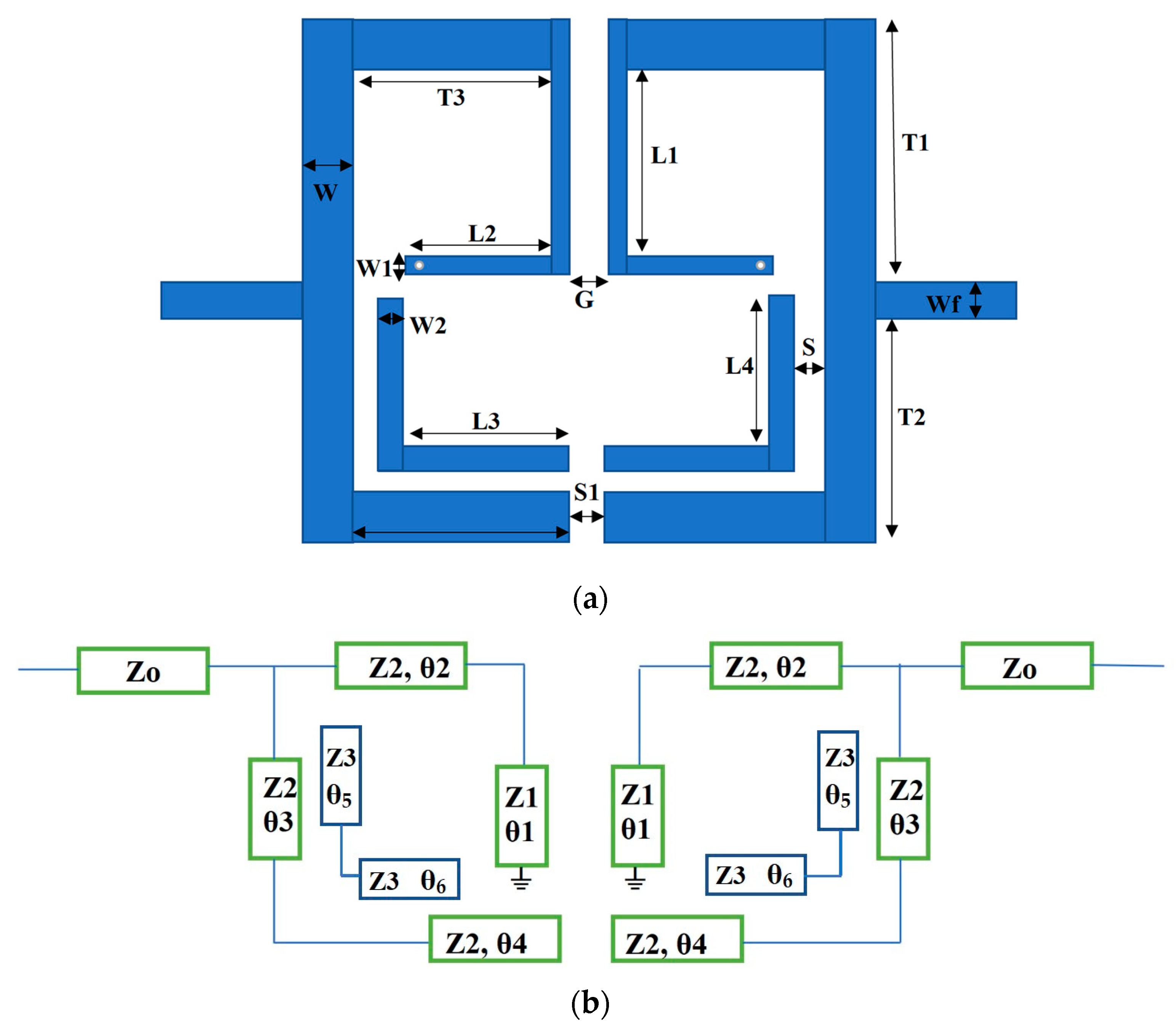
The proposed filter comprises two symmetrical step impedance resonator configurations with one end open-circuited and the other short-circuited, as depicted in Figure 2b. It consists of high/low impedances with characteristic impedances Z2/Z1 and electrical lengths θ21, respectively, as shown in Figure 2a. W1, L1 and W2, L2 are the physical widths and lengths of the low and high impedances. The low impedance sections are attached with 50-ohm input/output ports of the filter, and the high impedance sections are parallel coupled with metallic via at the lower corner having a radius of 0.25 mm. The first two passbands are obtained due to the ratio of the two impedances (R = Z2/Z1) of the SIR, and the third passband is obtained due to the L-shaped structure coupled to the high impedance section. The resonators are folded in a compact way to introduce magnetic and electric coupling for the generation of multiple TZs in the passbands. The electric coupling, which is a weak coupling in this case, is observed due to space S1 of the open-circuited stubs of the low-impedance section of the SIR. The magnetic coupling is observed due to gap G1 of the parallel short-circuited high-impedance section of the SIR. The input admittance Yin1 (Yin = 1/Zin) of Figure 2a is calculated as [42,43];
Y in 1 = j   R ( cot θ 1 tan θ 1   ) + ( cot θ 2 tan θ 2   ) Z 1   [ 0.5 ( cot θ 2 tan θ 2   ) ( cot θ 1 tan   θ 1 ) 2 R ]
where R   = Z 2 Z 1   and α = ( θ 2 θ 1 + θ 2 )
By tuning the impedance ratio R and electrical length ratio α, the first two passbands are obtained. Equation (1) can also be written as;
Y in 1 = jY 1 R     tan θ 1   tan θ 2 tan θ 1 + R   tan θ 2
where
  θ 1 = β 1 l 1 = ( 2 π λ ) = ( 2 π v p ) fl 1
and
θ 2 = β 2 l 2 = ( 2 π λ ) = ( 2 π v p ) fl 2
By applying the resonance condition, Equation (2) becomes.
R     tan θ 1   tan θ 2 = 0
In terms of resonance frequency ratio K, the unified resonant condition as derived in [44];
R   tan k x θ 1   tan k x θ 2 = 0
where
K x = f 2 f 1
The above analysis can be applied to Figure 2a. The same concept can also be applied to Figure 2b whose equivalent circuit is depicted in Figure 2c. So, the corresponding input admittance Yin2 for Figure 2b is
Yin 2 = jY 2 [   tan   ( kx θ 3 + k θ 4 ) R tan k x θ 1   tan k x θ 2 tan k x θ 1 + R   tan k x θ 2 ]
Now apply the resonant condition
R   tan k x   θ 1   tan k x   ( θ 2 + θ 3   + θ 4 ) = 0
The electrical lengths θ234 can be calculated easily by the required values of R and Kx. So, by adjusting the electrical lengths and impedance ratios, the first two passbands are obtained for GPS and WiMAX applications. Moreover, the final electrical lengths and impedances of Figure 2c on which the resultant SIR filter optimized are Z0 = 50 Ω, Z1 = 71 Ω, Z2 = 50 Ω, θ1 = 77, θ2 = 78.94, θ3 = 88.6, and θ4 = 15.

3. Triple Passband Filter Architecture

Figure 3a shows the overall layout of the triband bandpass filter, and Figure 3b shows its equivalent circuit model, which consists of a step impedance resonator with one end open-circuited and the other short-circuited. This type of configuration is also called λ/4 SIR with low and high impedance sections. The low impedance section Z1 is attached with the 50-ohm characteristic impedance input/outport of the filter, and the high impedance section Z2 is parallel coupled with metallic via at the lower end for size compactness. Moreover, the low impedance is also coupled to the embedded L-shaped λ/2 uniform structure. The first two passbands at 1.57 GHz and 3.57 GHz are obtained due to the coupled λ/4 SIR for GPS and WiMAX wireless applications, and the third passband at 4.23 GHz is obtained due to the embedded coupled L-shaped structure for satellite communication. All the resonators are folded to introduce coupling and sharpness in the filter by exciting multiple transmission zeros between the passbands. There is a total of eight T.Z.s excited at different locations, i.e., 1.22, 1.42, 1.98, 3.18, 3.82, 3.98, 4.38, and 4.53 GHz. After simulating the proposed filter in HFSS software, it is fabricated on substrate RO-4350 using milling machine LPKF S63 ProtoLaser and tested on ZNB-20 VNA. The overall dimensions and substrate properties are listed in Table 1.

4. Results and Discussion

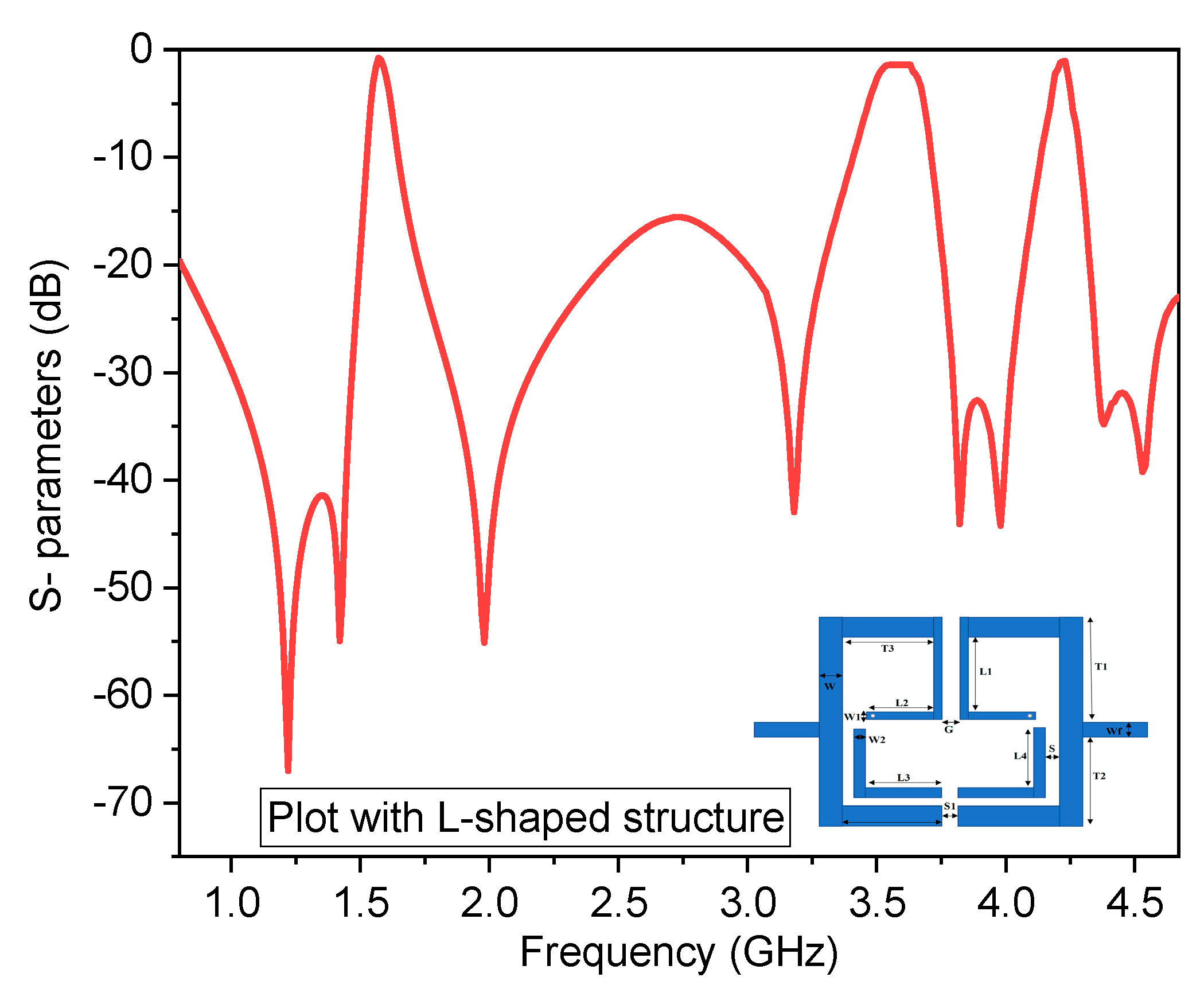
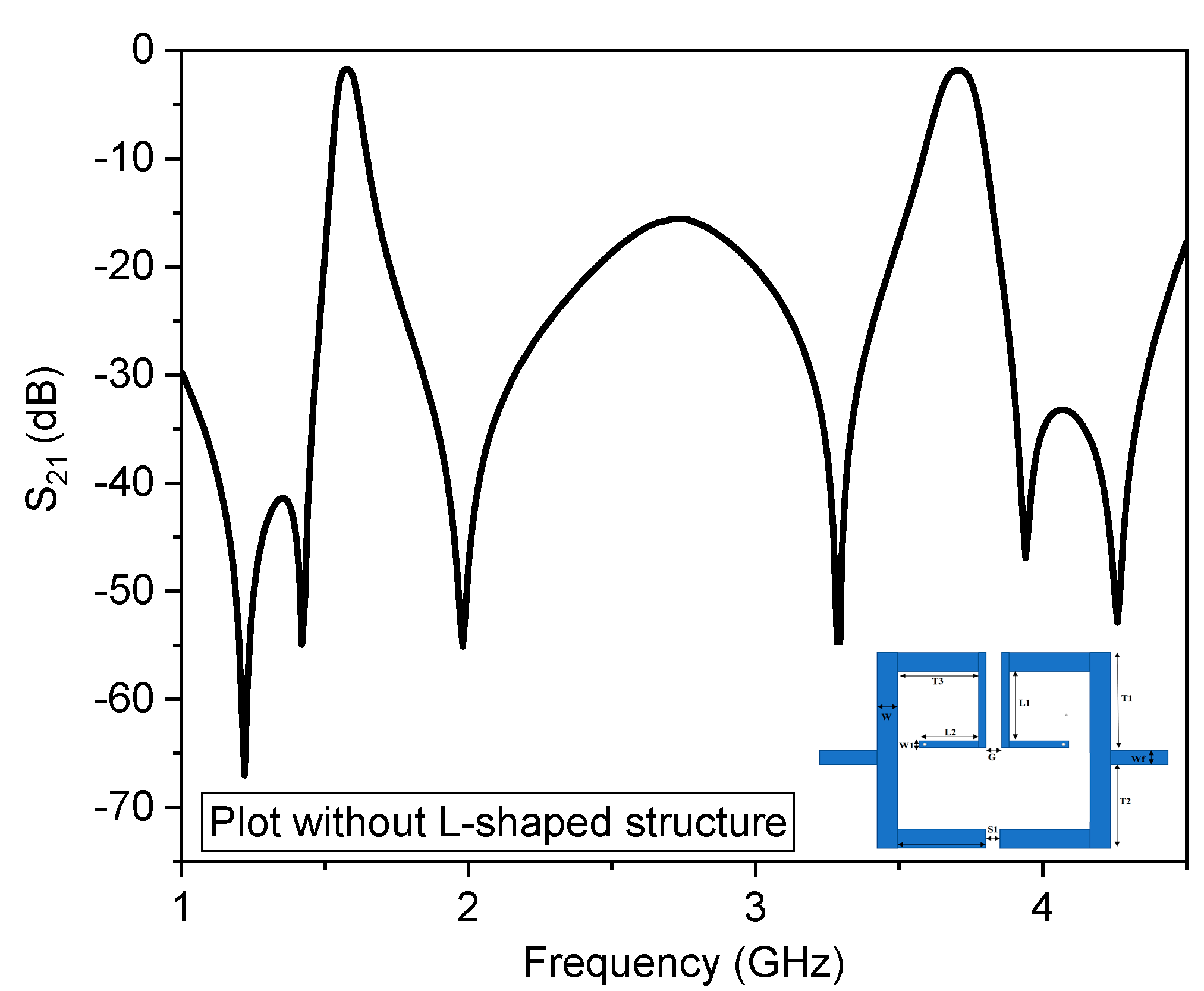
A high selectivity with eight transmission zeros triband bandpass filters is designed in this study. The proposed prototype combines low impedance section Z1 with one end open circuited and high impedance section Z2, which is folded to introduce coupling phenomena and size reduction with metallic via at lower edges. Later, a half-wavelength L-shaped resonator is further utilized for multi-passbands. The first two passbands for the applications of GPS and WiMAX are obtained due to the quarter wavelength step impedance resonator with electrical parameters Z0 = 50 Ω, Z1 = 71 Ω, Z2 = 50 Ω, θ1 = 77, θ2 = 78.94, θ3 = 88.6, and θ4 = 15 and the resonance frequency ratio Kx = f2/f1 which is 2.22 in this case. The electrical lengths of the proposed SIR can be changed to observe the first and second passbands. Consider Figure 4, which shows the variation of the first and second passband for electrical stub lengths θ1, where the upper cutoff frequency of the first band decreases with an increase of stub length θ1 and the upper and lower cutoff frequencies of the second band varied with no effect on third passband. Figure 5 shows that with the increase of electrical stub length θ4, only the lower cutoff frequency of the first passband and upper cutoff frequency of the second passband decreases with no effect on the third passband. This reveals that the first and second passbands are generated with the ratio of impedances and electrical stub lengths of the SIR. The third passband for satellite application is obtained due to the L-shaped structure embedded in the SIR. Thus, a triple band filter with multiple T.Z.s at different locations is obtained with the central frequencies 1.57 GHz, 3.57 GHz, and 4.2 GHz. The simulated results of the proposed prototype with and without the embedded L-shaped structure are illustrated in Figure 6 and Figure 7, where it is observed that the third passband is obtained due to the half-wavelength L-shaped resonator without affecting the first two passbands. Moreover, the third passband is controllable, and by varying the resonator length L4, the upper cut-off frequency is moved downward compared to the lower cut-off frequency without affecting the remaining passband cut-off frequencies, as shown in Figure 8, respectively.
To improve the selectivity of the filter, the structure is folded in a way that it can produce a coupling phenomenon; thus, a total of eight T.Z.s, including 1.22 (TZ1), 1.42 (TZ2), 1.98 (TZ3), 3.18 (TZ4), 3.82 (TZ5), 3.98 (TZ6), 4.38 (TZ7), and 4.53 (TZ8) have been observed between the passbands as shown in Figure 9. Due to these T.Z.s, the roll-off rates (ξ) of the three passbands increased. A higher roll-off rate indicates better selectivity, and it can be defined by regarding −20 dB attenuation and −3 dB attenuation as two cut-off points for the passband. It is equal to the rate of 17 dB with the bandwidth of roll-off [45]. Thus, the roll-off rates of the three passbands reach up to 294 dB/GHz (ξ1), 170 dB/GHz (ξ2), 106 dB/GHz (ξ3), 242 dB/GHz (ξ4), 106 dB/GHz (ξ5), and 121 dB/GHz (ξ6), respectively. The TZ1 and TZ6 are generated due to the mixed-coupling of the SIR, TZ2 and TZ5 are generated by the SIR itself, TZ3 and TZ4 are produced due to the metallic hole etched to the lower end of the high-impedance section of the SIR, while TZ7 and TZ8 are generated by the embedded L-shaped structure coupled to the low impedance of the SIR, respectively. Moreover, the proposed tri-band BPF has a maximum roll-off rate of up to 294 dB/GHz, demonstrating its great selectivity and abrupt roll-off.
The parameters frequently considered while designing bandpass filters are the coupling coefficient (K) and external quality factor (Q). The coupling coefficient describes the degree of energy transfer or closeness between two resonators, a physical quantity with no dimensions [46]. It was first incorporated into the microwave filter theory by M. Dishal [47]. He began with a bandpass network comprising a ladder chain of alternate series and parallel dissipative resonant circuits set to the same resonant frequency ω0 = 1/√L.C. The following design equation gives the exact values of coupling coefficients obtained in [48] for a certain asymmetrical pair of adjacent resonant circuits featuring Chebyshev frequency response.
| k | = ( ω 2 + ω 2 )   ±   ( ω 2 + + ω 2 )
where ω and ω+ are the lower and upper frequencies, and “w” is the relative bandwidth defined as
w = ( ω 2 ω 1 ) ω 1 ω 2
The next parameter is the external quality factor (Q), the ratio of the central resonance frequency to the 3 dB bandwidth. It can be determined by the outer resonator connecting to feeding lines and can be expressed as.
Quality   factor   ( Q ) = Resonance   frequency 3   dB   bandwidth
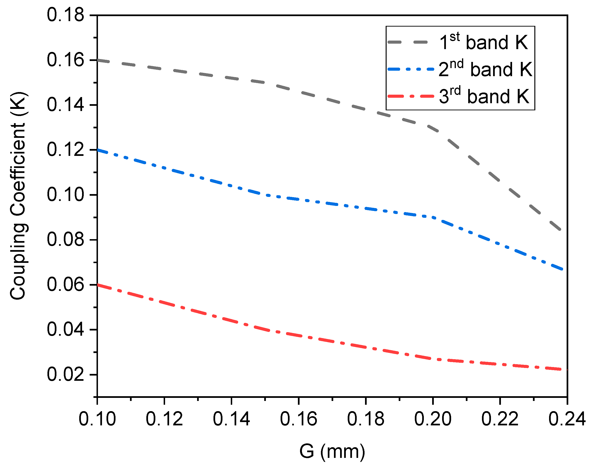
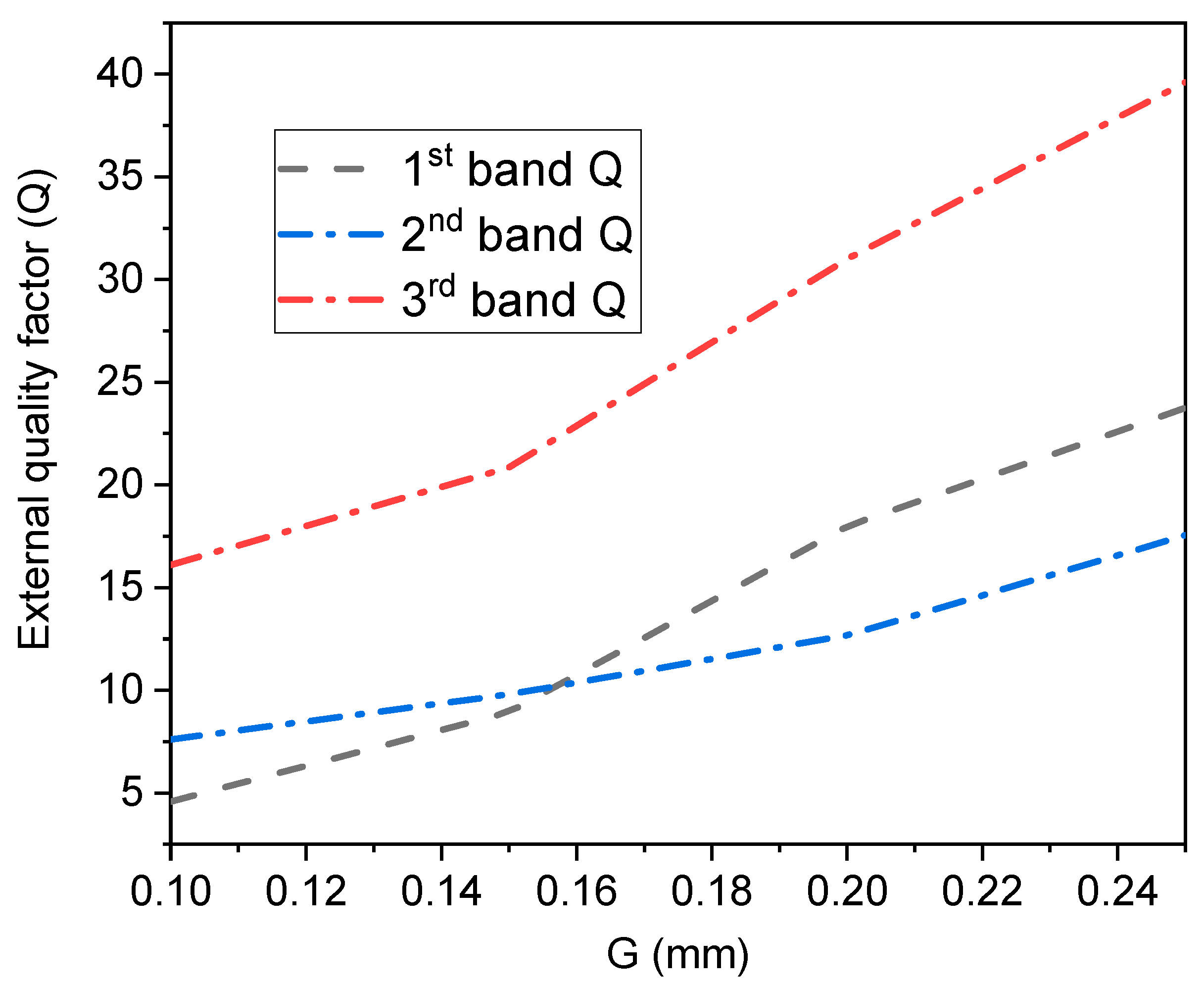
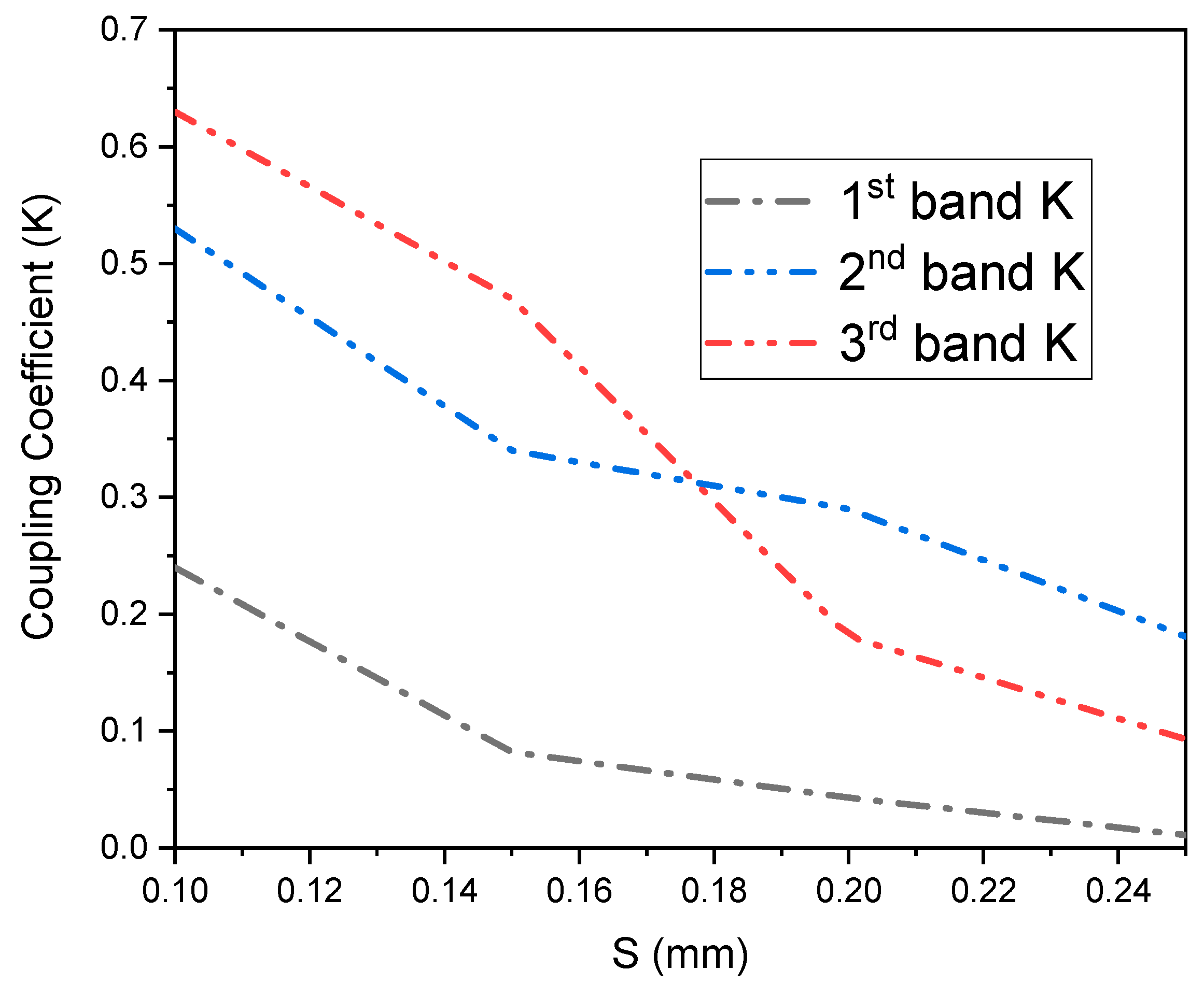
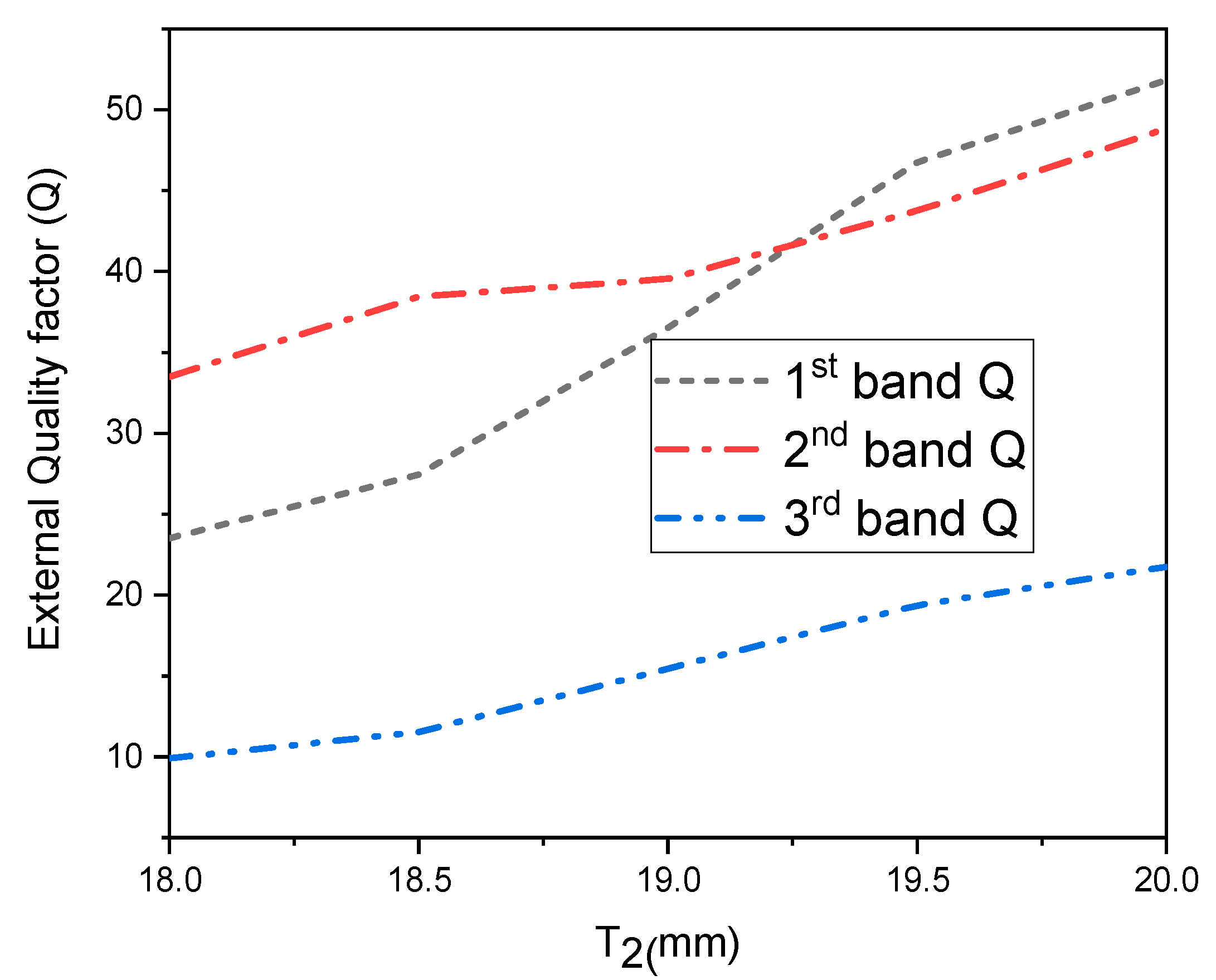
In Figure 3, the parameters G and S are responsible for K, while Q is achieved due to the parameter T2. The coupling coefficient decreases when the values G and S increase while the quality factor increases, as depicted in Figure 10, Figure 11 and Figure 12. Figure 13 shows the response of the three passbands’ quality factors concerning T2. The Q increases with varying values from 18 mm to 20 mm.
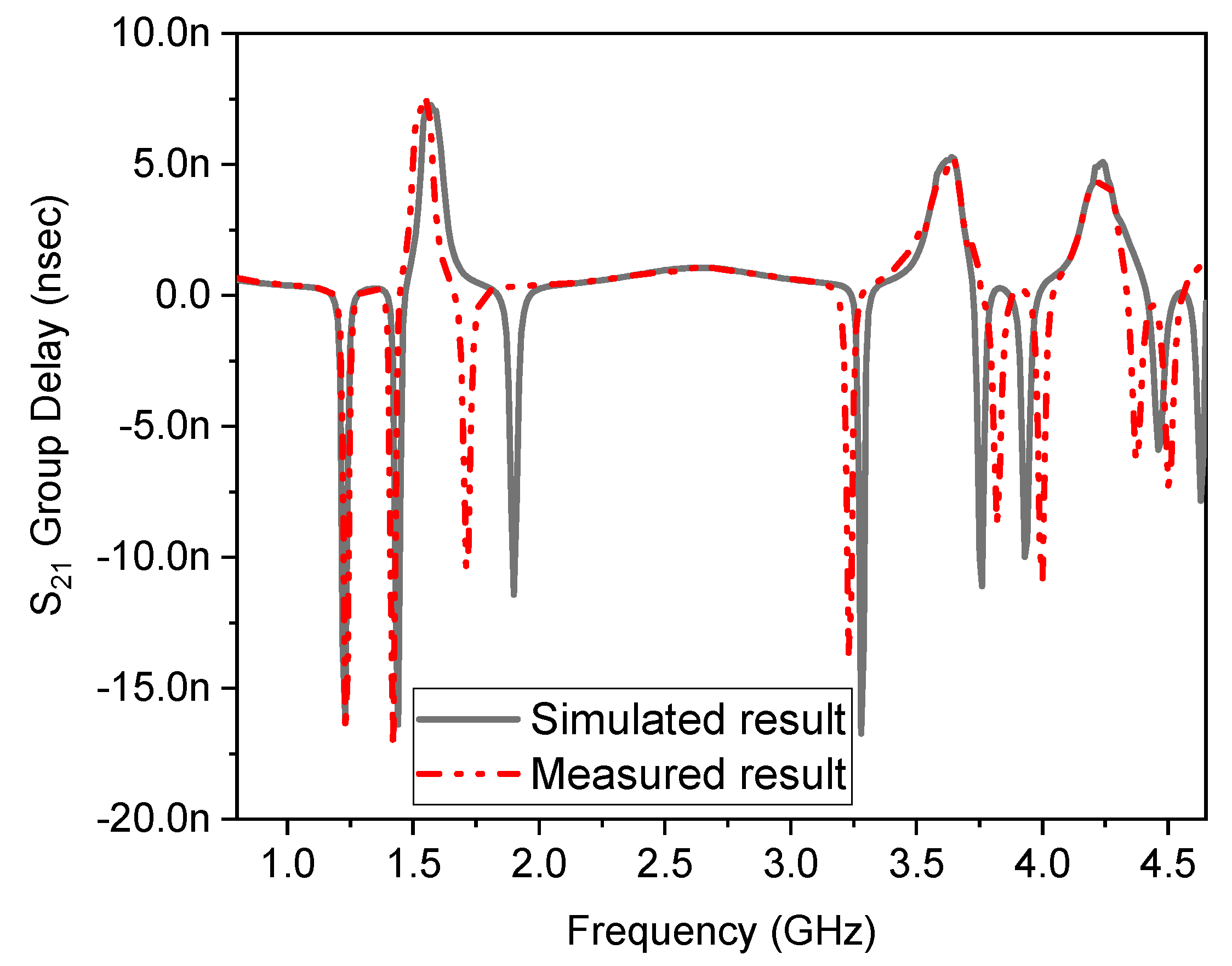
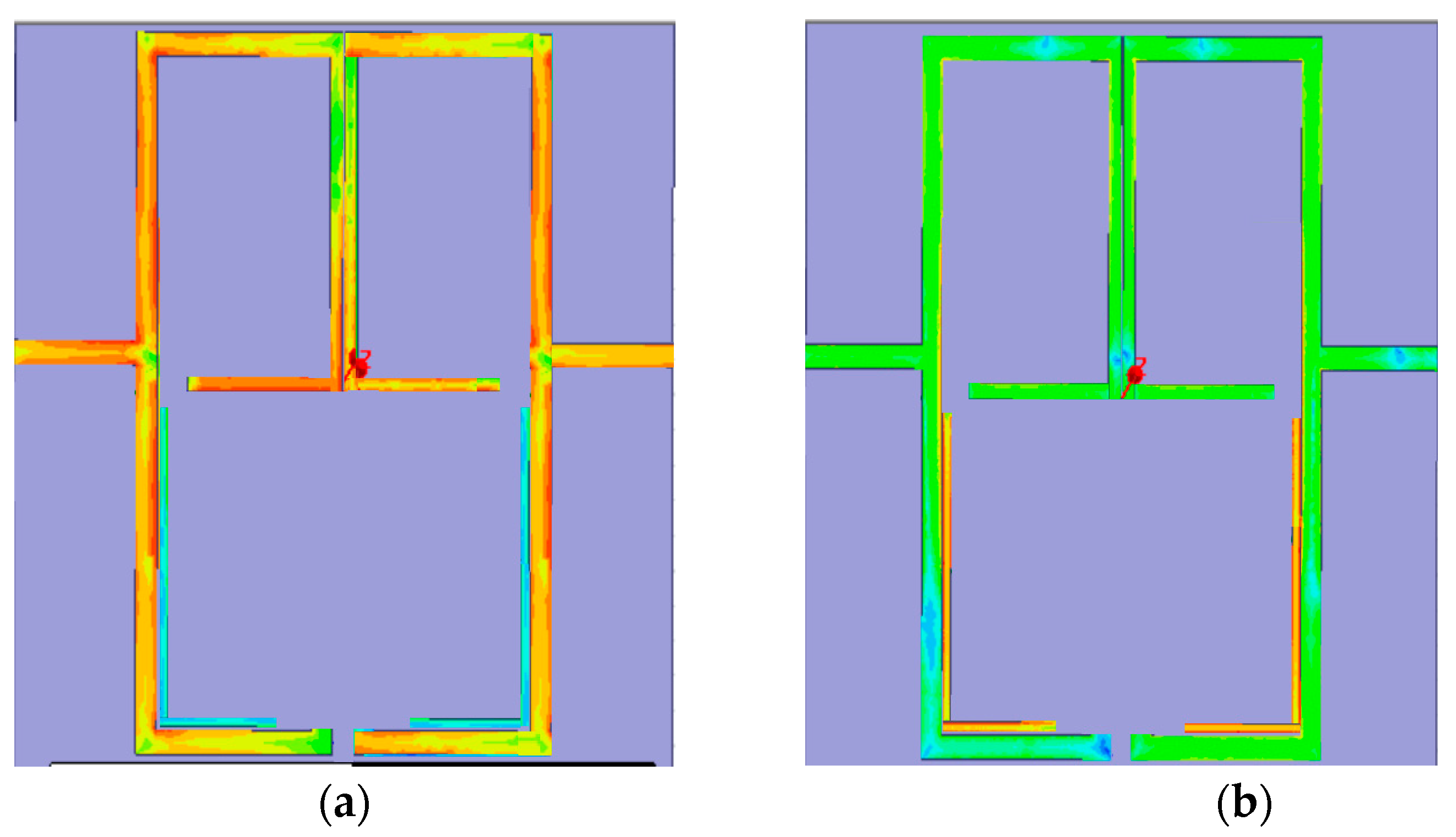
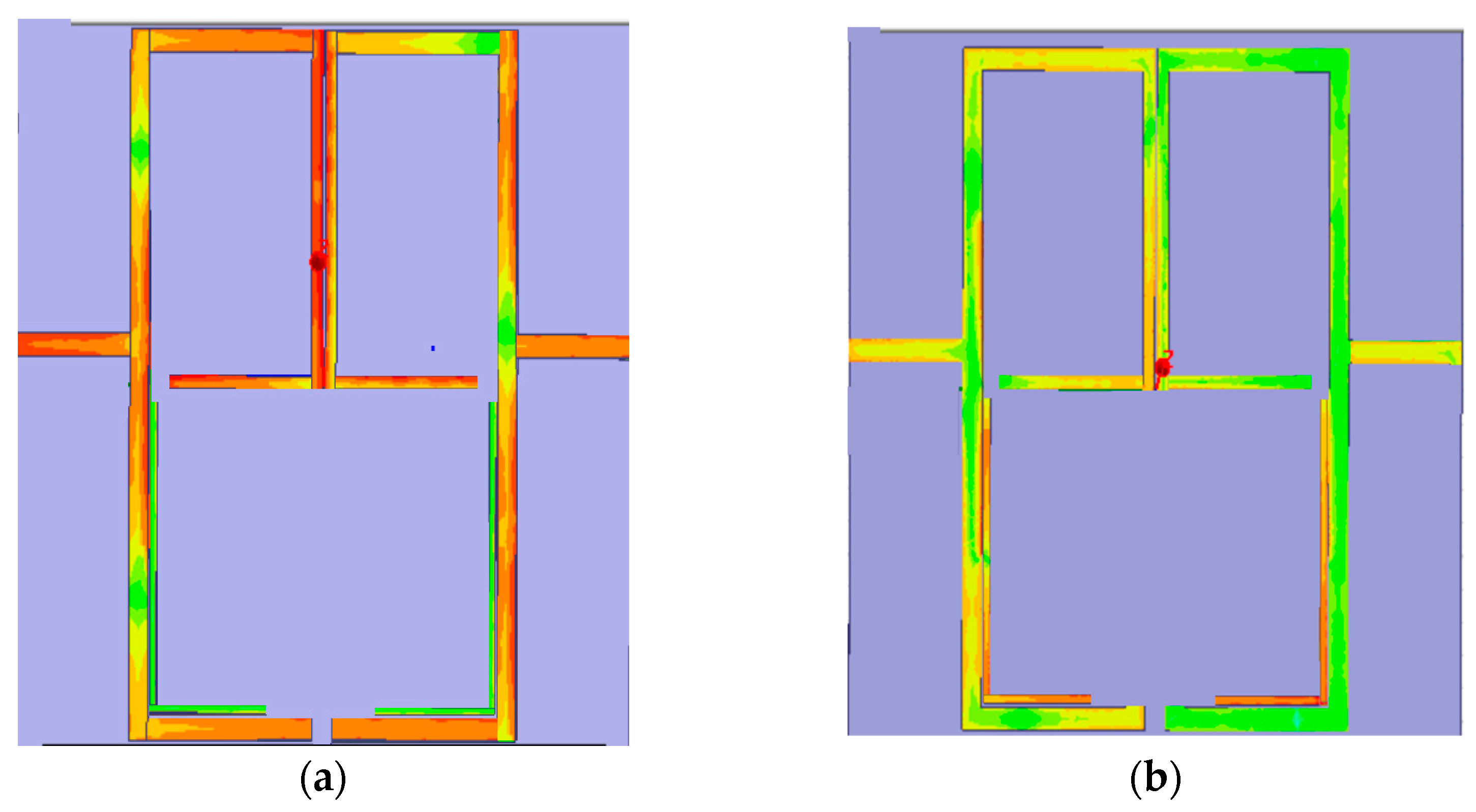
Figure 14 illustrates the group delay of the proposed triband filter. In designing bandpass filters, group delay is a crucial factor since it impacts the filter’s phase response. Group delay is a term that describes the delay that various frequency components of a signal endure as they pass through the filter [49]. To further validate the working principle, Figure 15 shows the current distribution of the proposed topology at the passbands. The current distribution indicates how the electrical current travels along the filter structure. It contributes to understanding signal propagation and the resonant behaviour of the filter [50]. As seen in Figure 15a, the current density is maximum on the surface of the SIR at frequency ratio K (f2/f1 = 2.2) because, as discussed, the first two passbands are obtained due to the ratio of the electrical lengths of the SIR. Figure 15b shows the current distribution at 4.23 GHz for the third passband, obtained by the embedded L-shaped resonator. As seen, the current is uniformly distributed only on the surface of the L-shaped resonator. Similarly, the magnitude of the electric field (E) intensity of the passbands is illustrated in Figure 16, respectively.

5. Fabrication and Measurement

In this article, a compact prototype with three passbands has been designed and fabricated to check the real-time performance. The filter was constructed using a step impedance resonator with metallic slots perturbation to the lower corner of the high impedance section to realise the first two passbands at 1.57 GHz for GPS and 3.5 GHz for WiMAX applications. The SIR was folded to reduce the circuit area, an essential requirement for communication system integration. The third passband at 4.23 GHz for satellite application is obtained using an L-shaped resonator coupled to the low impedance section of the SIR, resulting in a triband operating filter with good selectivity of multiple T.Z.s between the passbands. Eight T.Z.s were observed between the passbands at locations of 1.22/1.42/1.98/3.18/3.82/3.98/4.38/4.53 GHz, respectively. The suggested layout is fabricated on low tangent loss substrate material RO-4350 and tested on a ZNB-20 vector network analyzer. A good simulated and measured frequency plot of S11 and S21 is shown in Figure 17 was obtained. The proposed filter has low signal attenuation of less than 1.2 dB and high signal reflection of better than 25 dB for the three passbands. The fractional bandwidths achieved are 2.54%, 4.2%, and 1.65% at 1.57/3.57/4.23 GHz, respectively, with rejection levels in the stopband greater than 15 dB. The area occupied by the filter on a substrate or in a circuit is 0.31 λeff × 0.24 λeff (0.086 λg2), where λeff is the effective dielectric constant of the material calculated at the lowest frequency. Table 2 listed the comparison of this work with other triband filters in the literature in terms of size, FBW, IL, R.L., and selectivity.
After evaluating the above features, it is concluded that the prototype has good merits in a compact size, FBW, IL, R.L., and high sharp selectivity.

6. Conclusions

This manuscript successfully demonstrated and implemented a high selectivity and miniaturized triple-band bandpass filter for wireless applications where the first two passbands centred at 1.57 GHz and 3.57 GHz obtained from the ratio of impedances and electrical lengths of the λ/4 SIR and the third passband at 4.2 GHz is originated by the embedded L-shaped structure coupled to the low impedance section of the SIR. The fractional bandwidths of 2.54%, 4.2%, and 1.65% and insertion losses of 0.7 dB, 1.2 dB, and 1.08 dB are achieved with rejection levels in the stopband greater than 15 dB and return loss greater than 25 dB for all the three passbands, respectively. There are eight T.Z.s excited at 1.22/1.42/1.98/3.18/3.82/3.98/4.38/4.53 GHz, where the T.Z. at 1.2 GHz and 3.98 GHz are due to mixed-coupling of the SIR, the 1.42 GHz and 3.82 GHz by the SIR itself, the 1.98 GHz and 3.18 GHz are excited due to the metallic via at lower end of the SIR, and the last two are generated due to L-shaped structure coupled to the SIR, thus obtained a high sharp filter. Lastly, the structure was fabricated on Rogers PCB and observed an excellent matching between experimental and measured results. Owing to the above features, the prototype can be successfully implemented in real-world applications such as GPS, WiMAX, and Satellite communication systems. The author claimed that this work is the second high sharp filter along with the compact size and simple topology in the literature by introducing multiple T.Z.s in the passbands.

Author Contributions

Conceptualization, A.B. and G.Z.; methodology, A.B.; software, A.B., S.A.A., M.I.K. and A.D.; formal analysis, A.D.; investigation, A.B.; resources, S.A.A. and F.Z.; data curation, F.Z.; writing—original draft preparation, A.B.; writing—review and editing, G.Z.; visualization, A.B. and A.D.; supervision, G.Z.; project administration, G.Z.; funding acquisition, G.Z. All authors have read and agreed to the published version of the manuscript.

Funding

This Research is funded by Research Supporting Project Number (RSPD2023R585), King Saud University, Riyadh, Saudi Arabia.

Data Availability Statement

Not applicable.

Acknowledgments

The authors really appreciated the kind support from the Research Supporting Project Number (RSPD2023R585), King Saud University, Riyadh, Saudi Arabia.

Conflicts of Interest

The authors declare no conflict of interest.

References

  1. Pandey, P.; Pandey, A.K.; Chauhan, R.K. Novel Tri-band Microstrip Bandpass Filter with Stub Loaded in Circular Ring Resonator. In VLSI, Microwave and Wireless Technologies: Select Proceedings of ICVMWT 2021; Springer Nature: Singapore, 2022; pp. 357–366. [Google Scholar]
  2. Basit, A.; Khattak, M.I.; Al-Hasan, M.; Nebhen, J.; Jan, A. Design and Analysis of a Compact GSM/GPS Dual-Band Bandpass Filter Using a T-Shaped Resonator. J. Electromagn. Eng. Sci. 2022, 22, 138–145. [Google Scholar] [CrossRef]
  3. Massamba, O.C.; Mbango, F.M.; Lilonga-Boyenga, D. Four Subbands from Dual Mismatched Wideband Bandpass Filter for 5G/WAS/Wi-Fi/WiMAX/WLAN Applications. Int. J. RF Microw. Comput.-Aided Eng. 2023, 2023, 4713995. [Google Scholar] [CrossRef]
  4. Basit, A.; Khattak, M.I.; Althuwayb, A.; Nebhen, J. Compact Tri-band Bandpass Filter Based on Asymmetric Step Impedance Resonators for WiMAX and RFID Systems. J. Electromagn. Eng. Sci. 2021, 21, 316–321. [Google Scholar] [CrossRef]
  5. Xiu, Y.; Yang, W.C.; Jiang, M. Bandpass Filter Design with Stub-Loaded Uniform Impedance Resonator and L-Shaped Feed Structure. Prog. Electromagn. Res. Lett. 2022, 102, 19–26. [Google Scholar]
  6. Zhang, Y.P.; Li, X.J.; Phang, T.Y. A study of dual-mode bandpass filter integrated in BGA package for single-chip R.F. transceivers. IEEE Trans. Adv. Packag. 2006, 29, 2. [Google Scholar] [CrossRef]
  7. Jadidi, I.; Honarvar, M.A.; Khajeh-Khalili, F. Compact tri-band microstrip filter using three types of resonators for bluetooth, wimax, and wlan applications. Prog. Electromagn. Res. C 2019, 91, 241–252. [Google Scholar] [CrossRef]
  8. Kumar, B.A.; Meena, O.P. Design & simulation of a compact multi-band microstrip bandpass filter using C shaped stub loaded resonators. In Proceedings of the 2020 IEEE Conference Students Conference on Engineering & Systems (SCES), Prayagraj, India, 10–12 July 2020. [Google Scholar] [CrossRef]
  9. Sami, A.; Laso, M.A.G.; Lopetegi, T.; Arnedo, I.; Calero, I.; Teberio, F.; Iglesias, P.M.; Benito, D.; Arregui, I. Integrating multiple stubs in stepped-impedance filter aiming for high selectivity. Electron. Lett. 2022, 58, 554–556. [Google Scholar] [CrossRef]
  10. Carceller, C.; Soto, P.; Boria, V.; Guglielmi, M. Capacitive Obstacle Realizing Multiple Transmission Zeros for In-Line Rectangular Waveguide Filters. IEEE Microw. Wirel. Components Lett. 2016, 26, 795–797. [Google Scholar] [CrossRef]
  11. Pierce, J.R. Coupling of modes of propagation. J. Appl. Phys. 1954, 25, 179–183. [Google Scholar] [CrossRef]
  12. Kurzrok, R.M. General three-resonator filters in the waveguide. IEEE Trans. Microw. Theory Tech. 1966, 14, 46–47. [Google Scholar] [CrossRef]
  13. Cameron, R.J.; Rhodes, J.D. Asymmetric realizations for dual-mode bandpass filters. IEEE Trans. Microw. Theory Tech. 1981, 29, 51–58. [Google Scholar] [CrossRef]
  14. Levy, R. Direct synthesis of cascaded quadruplet (C.Q.) filters. IEEE Trans. Microw. Theory Tech. 1995, 43, 2940–2945. [Google Scholar] [CrossRef]
  15. Franti, L.F.; Paganuzzi, G.M. Odd-degree pseudoelliptical phase-equalized filter with asymmetric band-pass behavior. In Proceedings of the IEEE European Microwave Conference, Amsterdam, The Netherlands, 7–11 September 1981; pp. 111–116. [Google Scholar]
  16. Hong, J.S.; Lancaster, M.J. Microstrip triangular patch resonator filters. In Proceedings of the IEEE MTT-S International Microwave Symposium Digest, Boston, MA, USA, 11–16 June 2000; pp. 331–334. [Google Scholar]
  17. Bell, H.C. Canonical lowpass prototype network for symmetric coupled-resonator bandpass filters. Electron. Lett. 1974, 10, 265–266. [Google Scholar] [CrossRef]
  18. Bell, H.C. Canonical asymmetric coupled-resonator filters. IEEE Trans. Microw. Theory Tech. 1982, 30, 1335–1340. [Google Scholar] [CrossRef]
  19. Zhang, M.; Li, M.; Zhang, P.-J.; Duan, K.; Jin, B.; Huang, L.; Song, Y. A novel miniaturized bandpass filter basing on the stepped-impedance resonator. Prog. Electromagn. Res. Lett. 2021, 97, 77–85. [Google Scholar] [CrossRef]
  20. Ieu, W.; Zhou, D.; Zhang, D.; Lv, D. Compact dual-mode dual-band HMSIW bandpass filters using source-load coupling with multiple transmission zeros. Electron. Lett. 2019, 55, 210–222. [Google Scholar] [CrossRef]
  21. Wang, C.-H.; Lin, Y.-S.; Chen, C.H. Novel inductance-incorporated microstrip coupled-line bandpass filters with two attenuation poles. IEEE MTT-S Int. Microw. Symp. Dig. 2004, 3, 1979–1982. [Google Scholar]
  22. Wang, L.T.; Xiong, Y.; Wang, W.-J.; Gong, L.; Li, Z.; Li, X.Q.; Liang, Z.-L. Design of compact transversal wideband bandpass filter with wide upper stopband. Prog. Electromagn. Res. M 2020, 96, 79–87. [Google Scholar] [CrossRef]
  23. Sami, A.; Rahman, M. A very compact quintuple band bandpass filter using multimode stub loaded resonator. Prog. Electromagn. Res. C 2019, 93, 211–222. [Google Scholar] [CrossRef]
  24. Wattikornsirikul, N.; Kumngern, M. Dual-mode dual-band bandpass filter with asymmetrical transmission zeros. Prog. Electromagn. Res. M 2019, 86, 193–202. [Google Scholar] [CrossRef]
  25. Konpang, J.; Wattikornsirikul, N. Dual-mode dual-band bandpass filter with high cutoff rejection by using asymmetrical transmission zeros technique. Prog. Electromagn. Res. M 2021, 100, 225–236. [Google Scholar] [CrossRef]
  26. Wang, Y.X.; Chen, Y.L.; Zhou, W.H.; Yang, W.C.; Zen, J. Dual-band bandpass filter design using stub-loaded hairpin resonator and meandering uniform impedance resonator. Prog. Electromagn. Res. Lett. 2021, 95, 147–153. [Google Scholar] [CrossRef]
  27. Rahman, M.; Park, J.-D. A compact tri-band bandpass filter using two stub-loaded dual mode resonators. Prog. Electromagn. Res. M 2018, 64, 201–209. [Google Scholar] [CrossRef]
  28. Rahman, M.U.; Ko, D.-S.; Park, J.D. A compact tri-band bandpass filter utilizing double mode resonator with six transmission zeros. Microw. Opt. Technol. Lett. 2018, 60, 1767–1771. [Google Scholar] [CrossRef]
  29. Basit, A.; Khattak, M.I.; Nebhen, J.; Jan, A.; Ahmad, G. Investigation of external quality factor and coupling coefficient for a novel SIR based microstrip tri-band bandpass filter. PLoS ONE 2021, 16, e0258386. [Google Scholar] [CrossRef]
  30. Bi, X.; Wang, L.; Ma, Q.; Hu, B.; Xu, Q. A compact sept-band bandpass filter utilising a single multi-mode resonator. IET Microw. Antennas Propag. 2019, 13, 12. [Google Scholar] [CrossRef]
  31. Ren, B.; Guan, X.; Liu, H. Multi-band HTS bandpass filters using multimode square ring loaded resonators. In Proceedings of the IEEE Conference Cross-Strait Radio Science & Wireless Technology Conference (CSRSWTC), Fuzhou, China, 13–16 December 2020. [Google Scholar] [CrossRef]
  32. Liu, H.; Zhang, F.; Guo, C.; Xue, B.; Xu, J. An X-band waveguide bandpass filter with enhanced stopband using offset resonators. IEICE Electron. Express 2021, 18, 20200406. [Google Scholar] [CrossRef]
  33. Sukushi, T.; Ono, S.; Wada, K. Bandpass filter with flat passband and transmission zeros using parallel-connected resistor loaded hairpin-shaped resonators. IEICE Electron. Express 2020, 17, 20200320. [Google Scholar] [CrossRef]
  34. Hsu CI, G.; Lee, C.H.; Hsieh, Y.H. Tri-band bandpass filter with sharp passband skirts designed using tri-section SIRs. IEEE Microw. Wirel. Compon. Lett. A Publ. IEEE Microw. Theory Tech. Soc. 2008, 18, 1. [Google Scholar] [CrossRef]
  35. Lai, X.; Liang, C.H.; Di, H.; Wu, B. Design of tri-band filter based on stub loaded resonator and DGS resonator. IEEE Microw. Wirel. Compon. Lett. 2010, 20, 5. [Google Scholar] [CrossRef]
  36. Sheikh, T.A.; Borah, J.; Roy, S. Design a compact tri-band bandpass filter using asymmetric SIRs and DGS. In Proceedings of the International Conference on Energy, Power, and Environment: Towards Sustainable Growth (ICEPE), Shillong, India, 12–13 June 2015. [Google Scholar] [CrossRef]
  37. Xu, J.X.; Gao, L.; Xiang, J.; Xue, Q. Compact tri-band bandpass filter with controllable frequencies. Microw. Opt. Technol. Lett. 2016, 58, 573–577. [Google Scholar] [CrossRef]
  38. Gao, L.; Zhang, X.Y.; Xue, Q. Compact tri-band bandpass filter using novel eight-mode resonator for 5G WiFi application. IEEE Microw. Wirel. Compon. Lett. A Publ. IEEE Microw. Theory Tech. Soc. 2015, 25, 10. [Google Scholar] [CrossRef]
  39. Zhao, H.; Zhou, P.; Xu, Z.; Li, S.; Yang, M.; Liu, L.; Yin, X. Tri-band band-pass filter based on multi-mode spoof surface plasmon polaritons. IEEE Access 2020, 8, 14767–14776. [Google Scholar] [CrossRef]
  40. Bandyopadhyay, A.; Sarkar, P.; Mondal, T.; Ghatak, R. A dual function reconfigurable bandpass filter for wideband and tri-band operations. IEEE Trans. Circuits Syst. II Express Briefs 2021, 68, 1892–1896. [Google Scholar] [CrossRef]
  41. Weng, M.H.; Hsu, C.W.; Lin, Y.; Tsai, C.Y.; Yang, R.Y. A simple method to design a tri-bandpass filter using open-loop uniform impedance resonators. J. Electromagn. Waves Appl. 2020, 34, 103–115. [Google Scholar] [CrossRef]
  42. Basit, A.; Khattak, M.I. Designing modern compact microstrip planar quadband bandpass filter for hand-held wireless applications. Frequenz 2020, 74, 219–227. [Google Scholar] [CrossRef]
  43. Shang, Y.; Feng, W.; Che, W. Wideband reconfigurable bandpass filter using coupled lines loaded with varactor loaded stubs. Int. J. RF Microw. Comput. Aided Eng. 2018, 28, e21195. [Google Scholar] [CrossRef]
  44. Zhang, S.B.; Zhu, L. Synthesis design of dual-band bandpass filters with λ/4 stepped-impedance resonators. IEEE Trans. Microw. Theory Tech. 2013, 61, 1812–1819. [Google Scholar] [CrossRef]
  45. Zhu, L.; Guan, Y.; Zheng, B.; Cheng, Z. A high selectivity tri-band BPF using π-type structure loaded with λ/4 open stub and hybrid SIR. Microw. Opt. Technol. 2022, 64, 905–910. [Google Scholar] [CrossRef]
  46. Basit, A.; Khattak, M.I.; Zubir, F.; Shah, S.W. Miniaturized ultra-wideband filter with independently controlled notch bands for 5.1/6/8 GHz wireless applications. PLoS ONE 2022, 17, e0268886. [Google Scholar] [CrossRef]
  47. Dishal, M. Design of dissipative band-pass filters producing desired exact amplitude-frequency characteristics. Proc. IRE 1949, 37, 1050–1069. [Google Scholar] [CrossRef]
  48. Tyurnev, V.V. Direct derivation and refinement of generalized Cohn-Matthaei formulas for resonator coupling coefficients in a microwave filter. J. Commun. Technol. Electron. 2008, 53, 554–557. [Google Scholar] [CrossRef]
  49. Zhang, G.; Basit, A.; Khan, M.I.; Daraz, A.; Saqib, N.; Zubir, F. Multi-Frequency Controllable In-Band Suppressions in a Broad Bandwidth Microstrip Filter Design for 5G Wi-Fi and Satellite Communication Systems Utilizing a Quad-Mode Stub-Loaded Resonator. Micromachines 2023, 14, 866. [Google Scholar] [CrossRef]
  50. Basit, A.; Daraz, A.; Khan, M.I.; Saqib, N.; Zhang, G. Design, Modeling, and Implementation of Dual Notched UWB Bandpass Filter Employing Rectangular Stubs and Embedded L-Shaped Structure. Fractal Fract. 2023, 7, 112. [Google Scholar] [CrossRef]
  51. Wu, Y.; Ma, K.; Wang, Y. Coupling matrix design of compact multiband cascaded trisection bandpass filters. IEEE Trans. Circuits Syst. II Express Briefs 2022, 69, 2762–2766. [Google Scholar] [CrossRef]
  52. Liu, H.; Wang, Z.; Hu, S.; Xu, H.-X.; Ren, B. Design of Tri-Band Balanced Filter With Wideband Common-Mode Suppression and Upper Stopband Using Square Ring Loaded Resonator. IEEE Trans. Circuits Syst. II Express Briefs 2019, 67, 1760–1764. [Google Scholar] [CrossRef]
  53. Zhang, R.; Peroulis, D. Planar Multifrequency Wideband Bandpass Filters With Constant and Frequency Mappings. IEEE Trans. Microw. Theory Tech. 2018, 66, 935–942. [Google Scholar] [CrossRef]
  54. Wu, Y.; Fourn, E.; Besnier, P.; Quendo, C. Direct synthesis of multiband band-pass filters with generalized frequency transformation methods. IEEE Trans. Microw. Theory Techn. 2021, 69, 3820–3831. [Google Scholar] [CrossRef]
  55. Massamba, O.C.; Mpele, P.M.; Mbango, F.M.; Lilonga-Boyenga, D. Tri-Band Bandpass Filter Using Mixed Short/Open Circuited Stubs and Q-Factor with Controllable Bandwidth for WAS, ISM, and 5G Applications. Prog. Electromagn. Res. C 2022, 119, 177–190. [Google Scholar] [CrossRef]
  56. Pelluri, S.; Kartikeyan, M.V. Compact triple-band bandpass filter using multi-mode HMSIW cavity and half-mode DGS. Int. J. Microw. Wirel. Technol. 2021, 13, 103–110. [Google Scholar] [CrossRef]
  57. Berka, M.; Bendaoudi, A.; Benkhallouk, K.; Mahdjoub, Z.; Rouabhi, A.Y. Designing of tri-band bandpass microwave filter based on (E–Z) inter-coupled tapered metamaterial resonators for C-and X-band applications and operations. Appl. Phys. A 2022, 128, 1112. [Google Scholar] [CrossRef]
  58. Zhang, G.; Zhang, X.; Liu, S.; Tang, L.; Yang, J.; Hong, J.-S. Tri-band filtering power divider based on multi-mode fork-type resonator for performance enhancement. IET Microw. Antennas Propag. 2020, 14, 867–873. [Google Scholar] [CrossRef]
  59. Zhou, X.; Zhang, G.; Feng, S.; Tam, K.W.; Zhang, Z.; Tang, W.; Yang, J. Design of 3-D integrated SIWmultiband bandpass filter with split-type extended doublet topology. IEEE Trans. Compon. Packag. Manuf. Technol. 2022, 12, 1681–1691. [Google Scholar] [CrossRef]
  60. Riaz, M.; Virdee, B.S.; Mariyanayagam, D.; Salekzamankhani, S.; Benetatos, H.; Lubangakene, I. Sharp roll-off triband microstrip bandpass filter with wide stopband for multiband wireless communication systems. Int. J. RF Microw. Comput.-Aided Eng. 2022, 32, e23438. [Google Scholar] [CrossRef]
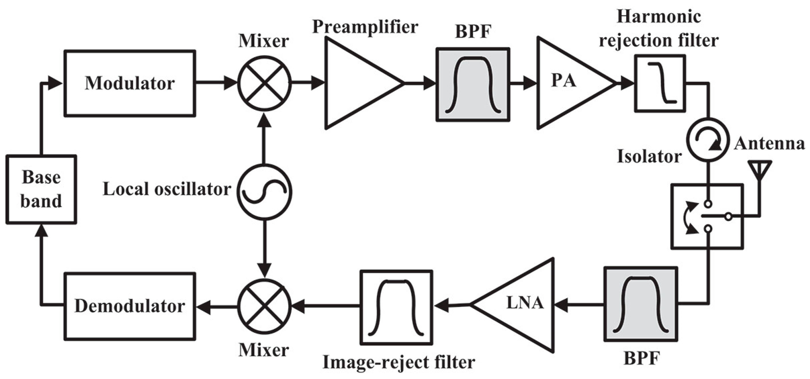
Figure 1. Placement of bandpass filter in communication systems [6].
Fractalfract 07 00511 g001
Figure 2. Configuration of resonators (a) Stepped impedance resonator (b) dual band filter topology (c) Equivalent structure of (b).
Fractalfract 07 00511 g002
Figure 3. (a) Proposed triband geometry. (b) Equivalent circuit model.
Fractalfract 07 00511 g003
Figure 4. Variations in cut-off frequencies w.r.t electrical length θ1.
Fractalfract 07 00511 g004
Figure 5. Variations in cut-off frequencies w.r.t electrical length θ4.
Fractalfract 07 00511 g005
Figure 6. Realization of the third passband by embedded L-shaped resonator.
Fractalfract 07 00511 g006
Figure 7. Response of filter without L-shaped structure.
Fractalfract 07 00511 g007
Figure 8. Variation in third pass band w.r.t stub length L4.
Fractalfract 07 00511 g008
Figure 9. Location of T.Z.s at different frequencies with sharpness factor.
Fractalfract 07 00511 g009
Figure 10. Effect of G parameter coupling coefficient on three passbands.
Fractalfract 07 00511 g010
Figure 11. Effect of G parameter external quality factor on three passbands.
Fractalfract 07 00511 g011
Figure 12. Effect of S parameter coupling coefficient on three passbands.
Fractalfract 07 00511 g012
Figure 13. Effect of T2 parameter external quality factor on three passbands.
Fractalfract 07 00511 g013
Figure 14. Group delay response of the three passbands.
Fractalfract 07 00511 g014
Figure 15. Nature of the current distribution of the triband filter (a) surface current density due to the frequency ratio K. (b) surface current density due to L-shaped resonator at 4.23 GHz.
Fractalfract 07 00511 g015
Figure 16. The magnitude of the electric field intensity (a) E due to the frequency ratio K. (b) E due to the L-shaped resonator at 4.23 GHz.
Fractalfract 07 00511 g016
Figure 17. Simulated and measured S11 and S21 plots of the proposed geometry.
Fractalfract 07 00511 g017
Table 1. Optimized filter dimensions in millimeter (mm).
T117.61T220.88L120
L29.5W1.35W10.8
W20.5L36.6L415
Wf1.6S0.1S11
G0.2PCB Height0.762εr3.66
Table 2. Comparison of performance of the proposed filter with other triband structures.
Ref No.YearBands (GHz)S21 (dB)S11 (dB)FBW (%)T.Z.sSize (mm)Size (λg2)
[39]20202.9/5.6/113/3.1/5>2046/18/63144 × 401.864
[40]20212.4/3.5/5.25<1.750/33/4311.6/4/6.7341 × 29.50.291
[41]20201.93/2.6/3.91.5/0.6/1.815/20/205/11/3517.2 × 24.50.415
[51]20223.2/3.4/3.72.65/1.95/2.6918.3/17.9/19.23.57/3.77/2.07575 × 51.50.469
[52]20192.45/3.5/5.250.7/0.9/0.638/32/251.2/2/1.52642 × 31.50.240
[53]20180.4/0.8/1.550.7/1.8/1.610/8.2/9.355.4/20.9/10.3556 × 311.72
[54]20212.05/2.55/3.11.98/2.17/2.0112.3/14.9/14.14.8/7.8/8372.1 × 68.51.931
[55]20224.1/6.1/14.42.1/1.3/4.0819.63/22/12.15.3/8.6/2.1222.42 × 7.620.094
[56]20216.28/13/19.121.6/2.5/2.222/26/219.5/6.2/4.548.5 × 150.119
[57]20224.2/7.36/9.351.38/4.86/1.2715.7/17/ 385.21/3.19/9.3422 × 180.803
[58]20201.52/2.0/2.365.32/4.2/6.815.4/19.1/17.33.56/8.6/2.75554.9 × 28.60.248
[59]202218.2/18.7/19.12.59/2.21/2.515.9/20.9/24.80.45/1.08/0.561.1 × 1.1 × 1.21.469
[60]20223.6/4.6/5.6<0.78>3011.9/11.9/11.9554.34 × 22.30.911
This work20231.57/3.57/4.230.7/1.2/1.0627/35/282.54/4.2/1.65840.1 × 220.086
Disclaimer/Publisher’s Note: The statements, opinions and data contained in all publications are solely those of the individual author(s) and contributor(s) and not of MDPI and/or the editor(s). MDPI and/or the editor(s) disclaim responsibility for any injury to people or property resulting from any ideas, methods, instructions or products referred to in the content.