Abstract
A sinuous antenna is a frequency-independent antenna known for its wide bandwidth and consistent gain, which makes it valuable in broadband applications such as ultrawideband (UWB) radar and ground-penetrating radar (GPR). However, sinuous antennas tend to be rather large. Consequently, numerous studies have explored miniaturization methods, with the gap-loading method emerging as a prominent approach. Unfortunately, it is still difficult to achieve broad bandwidths for conventional miniaturized sinuous antennas. In this paper, we use a novel approach incorporating a meander shape into the sinuous curve and employing gap loading with meandering. This innovative technique results in the development of a fractal-structured two-arm sinuous antenna characterized by an ultra-compact size and significantly expanded bandwidth. Adding a meander line in the outermost part maximizes the capacitance, thereby enhancing the gap-loading effect and minimizing the overall size of the sinuous antenna. In addition, the introduction of an inner meander line increases the inductance, contributing to a further expansion of the antenna’s bandwidth. For example, the electrical length of the antenna without the meander line is 0.552 × 0.552 × 0.052 , while the electrical length of the antenna with the meander line is only 0.445 × 0.445 × 0.036, i.e., 19.4% smaller. The antenna lacking the outermost meander line exhibits a 10 dB impedance bandwidth, spanning from 0.74 to 10.53 GHz. In contrast, the antenna featuring the outermost meander line has a 10 dB impedance bandwidth, extending from 0.51 to 10.72 GHz, which results in a remarkable enhancement in the fractional bandwidth (by 8.1%). Hence, the proposed antenna design is a good candidate for broadband applications that require miniaturization.
1. Introduction
Today, we rely on numerous wireless communication services, including mobile communication, wireless local area networks (WLANs), Bluetooth, near-field communication (NFC), and others. The usage of wireless communication devices continues to experience significant growth. Moreover, research is underway for new wireless communication technologies, such as Wi-Fi 7 and 6G, which are expected to further drive the growth of the wireless communication market. Wireless communication requires antennas, and the performance of antennas can vary significantly based on their type, frequency band, size, and construction. Consequently, extensive research is being conducted on various antenna types to cater to diverse applications [1,2,3,4,5,6,7,8,9,10].
More recently, as electronic devices such as smartphones, laptops, and tablets have become more compact, the need for miniaturized antennas that can fit into these devices has also increased [11,12]. In addition, the array of wireless communication technologies employed in electronic devices such as GPS, Bluetooth, and radar are continually diversifying. To efficiently utilize these wireless communication technologies, there is a growing demand for wideband antennas capable of covering a broad frequency spectrum with a single antenna. Therefore, the need for miniaturized antennas that provide broadband coverage continues to grow. For miniaturized antennas, mainly microstrip patch antennas have been studied [13,14,15,16,17,18,19]. However, the narrow band of patch antennas limits their broadband applicability. To bypass this limitation, either fractal antennas with multiband characteristics or broadband antennas, such as Vivaldi antennas and printed monopole antennas, can be used. Fractal antennas may be suitable for narrowband communication applications, but they are impractical for applications that require broadband, such as direction-finding systems, ground-penetrating radar (GPR), and ultrawideband radar (UWB). Fractal antennas can also be designed to be broadband, having the same broadband characteristics as Vivaldi antennas or printed monopole antennas. However, typical broadband antennas have the disadvantage that their radiation pattern is not constant with respect to frequency, which can cause other problems. This challenge can be effectively addressed by employing frequency-independent antennas that maintain consistent antenna characteristics, including input impedance, gain, polarization, and radiation pattern, across a wide frequency band.
The sinuous antenna, categorized as a frequency-independent antenna, combines spiral and log-periodic characteristics. It was initially introduced by Duhamel in 1987 [20]. Using frequency-independent characteristics, sinuous antennas were found to be suitable for various applications such as UWB radar [21,22,23], GPR [24,25], electromagnetic pulse (EMP) [26], electronic support measures (ESMs) [27], and direction-finding systems [28,29]. However, the antennas studied were designed to meet the performance requirements of the application, and the sizes of the antennas were not considered.
Because the size of a sinuous antenna is determined by its lowest operating frequency, designing an antenna for a lower frequency inevitably results in a larger antenna. While it offers the advantage of being a frequency-independent antenna, its size surpasses that of other antennas, such as microstrip patch antennas, printed antennas, and monopole antennas. Consequently, its application to various scenarios can be challenging due to its larger size. To address this challenge, researchers have attempted to apply the gap-loading technique to conventional sinuous antenna designs [27,30] or modify sinuous curve designs to enable miniaturization [23].
However, antennas that have been the subject of study with an emphasis on miniaturization often encounter the drawback of narrow bandwidths or still have substantial electrical lengths. Therefore, it is desirable to study antennas with ultrawideband characteristics while minimizing their electrical length.
In this paper, we propose a fractal-structured two-arm sinuous antenna designed to achieve both miniaturization and enhanced bandwidth. The structure of the proposed antenna is based on a geometric fractal design created by incorporating a meander shape into the sinuous curve. This innovative approach addresses the challenge of miniaturizing the antenna while simultaneously enhancing its bandwidth. Specifically, the proposed antenna employs two techniques to enhance the original sinuous antenna design. First, a meander shape is applied to the original sinuous curve to create inductance and improve the bandwidth. Second, the gap-loading technique was newly applied to the meander shape to maximize capacitance loading and reduce the electrical length of the antenna significantly. The so-designed antenna was fabricated using a printed circuit board (PCB) process and compared with the simulation results following measurements. The proposed antenna is well-suited for applications demanding both broadband frequency characteristics and miniaturization.
2. Antenna Principle
Figure 1 shows the geometry and design parameters of a two-arm sinuous antenna, which represents the basic structure of the proposed antenna. The sinuous antenna can be designed using the sinuous curve equation proposed by Duhamel, which can be described as [20]:
where and φ are the radius and angle in the polar coordinate system, respectively; and and are the outer radius of the th and p + 1st cells, respectively. Furthermore, τ denotes the reduction factor, which is determined as the ratio of the outer radius of the th cell to the p + 1st cell. is the angular width of the th cell. δ signifies the rotation angle of each cell about the origin.
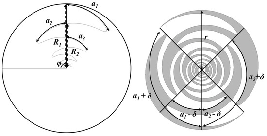
Figure 1.
Schematic illustrating the two-arm sinuous antenna’s geometry and its design parameters.
The lowest and highest operating frequencies of the sinuous antenna are given by the following equations [20,31]:
where is the wavelength corresponding to the lowest operating frequency,
is the wavelength corresponding to the highest operating frequency, and is the radius of the last cell. As the operating frequency of the antenna decreases, the outermost cell of the antenna, , becomes larger. Therefore, the lowest operating frequency of a sinuous antenna is determined by R1, the outer radius of the outermost cell, which also determines the size of the antenna. Designing a sinuous antenna as a self-complementary structure ensures that the input impedance of the antenna has a constant characteristic that is independent of frequency. This condition is expressed as:
where N denotes the number of arms of the sinuous antenna. Since the number of arms N of the designed sinuous antenna is two, is fixed at 45°. The mode impedance of a sinuous antenna with a self-complementary structure can be defined as [31]:
where is the impedance of each arm with respect to ground, and m is the operating mode of the sinuous antenna. A sinuous antenna with N arms has N−1 modes, and the input impedance changes depending on the mode. Since the sinuous antenna in this paper has two arms, the impedance of each arm, which operates in mode−1, is 94.2 Ω, and the input impedance is 188.4 Ω according to Equation (5).
3. The Proposed Antenna Design
3.1. Applying the Meander Shape to a Basic Sinuous Antenna
The proposed antenna can be designed by combining the sinuous curve equation in Equation (1) with the meander function. The meander function is given by
where is a parameter, denotes the starting point of the meander, and represents the endpoint of the meander. signifies the amplitude proportionality constant of the meander, and is the angular frequency. By adjusting the parameters in the equation, we can determine the start and end points of the meander line applied to a cell and adjust its amplitude. The meander shape, combined with the sinuous curve, increases the inductance, which enhances the bandwidth. Figure 2 illustrates the iterative process of progressively incorporating meandering into a basic sinuous antenna, ultimately resulting in the final proposed fractal sinuous antenna structure. In the outermost part of the proposed antenna, a meander-shaped ring is added using the gap-loading technique [32]. The ring increases the capacitance between the inner cell and the ring, maximizing the gap-loading effect and reducing the electrical size of the antenna while reducing impedance fluctuations at low frequencies. Figure 3 provides a visual representation of the parameters of the proposed antenna in addition to those of existing sinuous antennas.
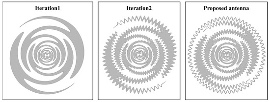
Figure 2.
The iterative process of progressively incorporating meandering into a basic sinuous antenna configuration.
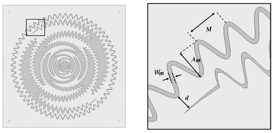
Figure 3.
Proposed antenna geometry and the related design parameters.
The input impedance of the two-arm sinuous antenna is about 188.4 Ω, which is higher than the impedance used in common antennas (50 Ω) such as patch antennas and monopole antennas. Therefore, it is necessary to match the antenna to a characteristic impedance of 50 Ω. In this paper, a broadband balun, which is often used to match broadband antennas, is employed to match the antenna’s impedance. Figure 4a shows the structure of the proposed antenna coupled with the balun. Many types of taper can be used in baluns for impedance matching. We used the Klopfenstein taper. The Klopfenstein taper features good return loss characteristics in the passband [33] and has been used in several studies [34,35,36]. Figure 4b, c show the top and bottom views of the Klopfenstein tapered balun, respectively.
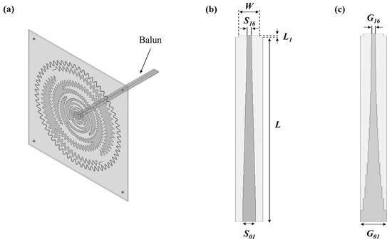
Figure 4.
(a) Structure of the antenna combined with the balun; (b) top view of the balun; and (c) bottom view of the balun.
In this study, a basic sinuous antenna with a lowest operating frequency of 800 MHz was designed to determine the performance of the proposed antenna. Its compatibility with wireless communications is maintained using various frequencies such as mobile communications, WLAN, and GPS. A meander shape was used for the designed antenna, and the gap-loading technique was employed to design the final antenna structure. The dielectric of the antenna was a 1.6 mm thick TLX-9 (dielectric constant = 2.5, loss tangent = 0.0019) substrate from Taconic (Petersburgh, NY, USA). The antenna design and simulation were performed using Ansys HFSS software (Canonsburg, PA, USA). Table 1 shows the proposed antenna and balun dimensions.

Table 1.
Proposed antenna and balun dimensions.
3.2. Proposed Antenna Simulation
Figure 5 shows the simulated reflection coefficient of the interation1 structure, the interation2 structure, and the proposed antenna, and the results are compared. The lowest operating frequencies of the three antennas were 0.74, 0.62, and 0.52 GHz, respectively, while the highest operating frequency was 10.53 GHz. The reason why all three antennas showed the same peak operating frequency is that neither the interation2 structure nor the new antenna structure uses a meander shape on the inside of the cell.
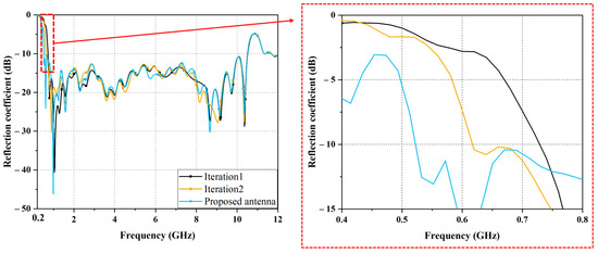
Figure 5.
Simulated reflection coefficient results when meandering increased iteratively.
Figure 6 shows the reflection coefficient results for the proposed antenna structure simulated by varying the amplitude proportionality constant , the angular frequency , the gap-loading distance , and the gap-loading width Wm. From Figure 6a, it can be seen that the lowest resonant frequency decreases with increasing until 3.5 mm. However, starting from 4 mm, the reflection coefficient value decreases to −10 dB or less after the lowest operating frequency. Figure 6b shows that the lowest operating frequency decreases as each frequency increases, especially when changes from 10 to 30, and the change in operating frequency is small when changes from 30 to 50. Figure 6c shows that the operating frequency decreases sharply from 0.62 GHz to 0.52 GHz when gap loading is used, albeit the change in gap is insignificant. Figure 6d shows that when the linewidth of the gap-loading ring is 0.5 mm, only the 0.6–0.64 GHz band of the 0.5–0.7 GHz band satisfies the reflection coefficient value (−10 dB). In addition, when the linewidth is 1 mm or more, the reflection coefficient of −10 dB is satisfied from 0.52 GHz. Figure 7a–f show the simulated current distribution results at 0.6, 0.8, 2, 5, 8, and 10 GHz. At 0.6 GHz, the current distribution shows that there is a strong current flowing outside the antenna arm and in the gap-loading ring. The current distribution at a frequency of 0.8 GHz shows a weakening of the current distribution formed on the outside of the antenna arm and the gap-loading ring compared to the 0.6 GHz current distribution. At 2 GHz, the current distribution exhibits a diminished outward current distribution in comparison to the current distribution observed at 0.8 GHz. Looking at the current distribution at 5, 8, and 10 GHz, we can see that the current distribution becomes progressively weaker from the outer cells. The outer of the proposed antenna arm and the gap-loading ring contribute to the lowest operating frequency radiation, while the cells inside the antenna contribute to the higher frequency radiation.
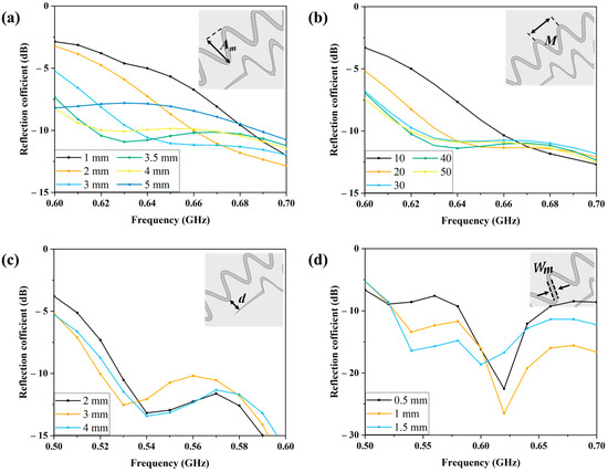
Figure 6.
Simulation results for the reflection coefficient as a function of (a) amplitude constant Am; (b) angular frequency M; (c) gap-loading distance d; and (d) gap-loading width Wm.
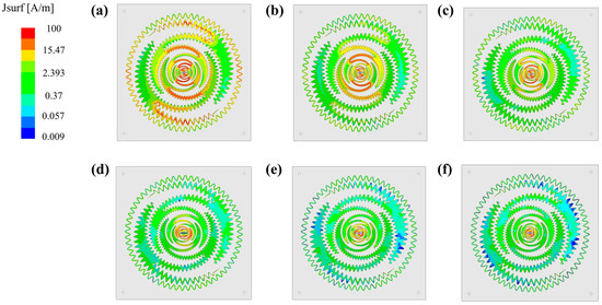
Figure 7.
Simulated magnitude of the current distribution for (a) 0.6 GHz; (b) 0.8 GHz; (c) 2 GHz; (d) 5 GHz; (e) 8 GHz; and (f) 10 GHz.
4. Experiment and Discussion
Figure 8a,b show the top and side views of the fabricated antenna, respectively. To fix the antenna combined with the balun, plastic bars and plastic screws were connected at 30°, 120°, 210°, and 330° from the antenna plane, respectively, and a square FR4 substrate (with no metal pattern underneath) was used to complete the installation of the plastic bars. The reflection coefficient and radiation patterns of the fabricated antenna were measured. A Keysight FieldFox N9951A network analyzer (Santa Rosa, CA, USA) was used to measure the reflection coefficient of the antenna. Figure 8c shows the far-field radiation-pattern measurement environment.

Figure 8.
Fabricated prototype antenna: (a) top view; (b) side view; and (c) far-field-radiation pattern measurement setup.
Figure 9 compares the simulated and measured reflection coefficients of the proposed synergistic antenna. The simulated and measured results are 0.52 GHz to 10.51 GHz and 0.51 GHz to 10.72 GHz, respectively. Expressed as fractional bandwidth, these numbers correspond to 181.1% and 181.8%, respectively. The simulated and measured reflection coefficient results are in good agreement. Figure 10 shows a comparison of the simulated and measured radiation patterns. For both the E-plane and H-plane radiation patterns, the beams formed in the broadside direction (relative to the plane where the antenna was placed). The peak gains in the 0.8, 2, 5, 8, and 10 GHz frequency bands were 4, 5, 6.42, 5.38, and 4.44 dBi, respectively. Figure 11 shows the peak gains with frequency. Within the operating frequency, the peak gain varied between −3.5 and 8.2 dBi, with an average peak gain of 4.77 dBi. In Figure 10 and Figure 11, discrepancies between the simulation and measurement results and ripples from radiation patterns are observed especially at high frequencies. They are due to fabrication and measurement errors. For instance, the soldering between the feeding line and subminiature version A (SMA) connector may affect the results. In addition, because a broadband standard gain antenna was used to measure the radiation pattern, its beamwidth was not much narrower at higher frequencies. Thus, the measurement error became larger especially at higher frequencies.
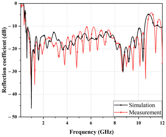
Figure 9.
Simulated and measured reflection coefficient results for the proposed sinuous antenna.
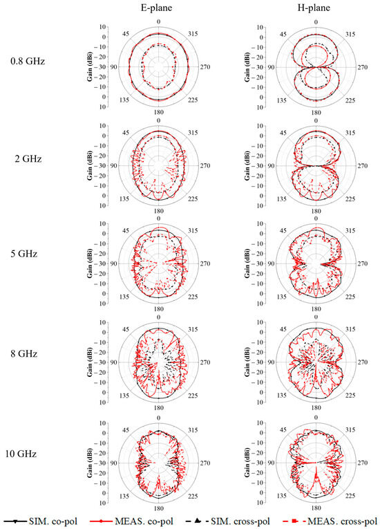
Figure 10.
Simulated and measured radiation patterns for the proposed sinuous antenna.
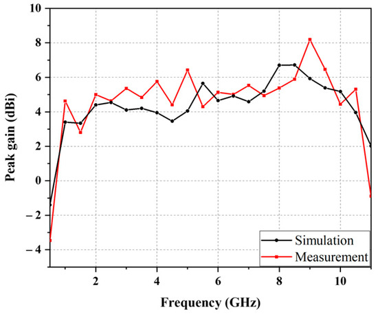
Figure 11.
Simulated and measured peak gain for the proposed sinuous antenna.
Table 2 presents a comparative analysis between the proposed sinuous antenna and prior research on sinuous antennas. Notably, previous studies have explored sinuous antennas with wide bandwidth characteristics [22,23,24,27,28,37]. Other research groups have used lenses to achieve high gain [38,39] or improved the cross-polarization isolation of the antenna [40]. However, they all obtained narrower bandwidths than our proposed antenna or still required large electrical lengths. The fractal-structured two-arm sinuous antenna proposed in this paper has a 9.7% wider bandwidth and a 10.1% smaller size than previously studied antennas.

Table 2.
Comparison of the new fractal structure sinuous antenna with other sinuous antennas.
5. Conclusions
In this paper, a novel miniaturized fractal-structured two-arm sinuous antenna with enhanced bandwidth is proposed. The proposed antenna has a geometric fractal structure, which is obtained by adding a meander shape to a sinuous curve. The gap-loading technique applied to the outermost part of the antenna and the meander-shaped sinuous shape formed inside the antenna were successfully used to enable significant miniaturization and bandwidth improvements. The measured bandwidth of the antenna ranged from 0.51 to 10.72 GHz, which is useful for various wireless communication services such as GPR, UWB radar, and WLAN. The electrical length of this antenna is 0.443 , which is smaller than that of previously studied sinuous antennas. The fractional bandwidth, both with and without the proposed fractal structure, demonstrates a difference of 8.1%. Furthermore, the electrical length exhibits a difference of 19.4% between the two configurations. The proposed fractal-structured two-arm sinuous antenna may be utilized in broadband applications that require broad bandwidth and small size.
Author Contributions
Conceptualization, T.Y. and S.L.; methodology, J.K. (Junghyeon Kim), J.K. (Jongho Keun), T.Y. and S.L.; software, J.K. (Junghyeon Kim) and J.K. (Jongho Keun); validation, J.K. (Junghyeon Kim) and J.K. (Jongho Keun); formal analysis, J.K. (Junghyeon Kim); investigation, J.K. (Junghyeon Kim), J.K. (Jongho Keun) and S.L.; resources, J.K. (Junghyeon Kim) and J.K. (Jongho Keun); data curation, J.K. (Junghyeon Kim) and J.K. (Jongho Keun); writing—original draft preparation, J.K. (Junghyeon Kim); visualization, J.K. (Junghyeon Kim); supervision, S.L.; project administration, S.L.; funding acquisition, S.L. All authors have read and agreed to the published version of the manuscript.
Funding
This research was supported by the National Research Foundation of Korea (NRF) grant funded by the Korea government (MSIT) (2021R1A2C3005239) and the MSIT (Ministry of Science and ICT), Korea, under the ITRC (Information Technology Research Center) support program (IITP-2023-RS-2022-00156353) supervised by the IITP (Institute for Information & Communications Technology Planning & Evaluation).
Data Availability Statement
Data are contained within the article.
Conflicts of Interest
The authors declare no conflict of interest.
References
- Chou, H.; Su, H. Dual-Band Hybrid Antenna Structure with Spatial Diversity for DTV and WLAN Applications. IEEE Trans. Antennas Propag. 2017, 65, 4850–4853. [Google Scholar] [CrossRef]
- Bisht, N.; Malik, P.K.; Das, S.; Islam, T.; Asha, S.; Alathbah, M. Design of a Modified MIMO Antenna Based on Tweaked Spherical Fractal Geometry for 5G New Radio (NR) Band N258. Fractal Fract. 2023, 258, 10. [Google Scholar]
- Han, B.; Wang, S.; Shi, X. Design of Compact Fragment-Type Antenna Array for Microwave-Based Head Imaging Application. J. Electromagn. Eng. Sci. 2023, 23, 344–350. [Google Scholar] [CrossRef]
- Koohestani, M.; Azadi-Tinat, N.; Skrivervik, A.K. Compact Slit-Loaded ACS-Fed Monopole Antenna for Bluetooth and UWB Systems with WLAN Band-Stop Capability. IEEE Access 2023, 11, 7540–7550. [Google Scholar] [CrossRef]
- Voronov, A.; Sydoruk, O.; Syms, R.R.A. Waveguide Antenna Topologies for Distributed High-Frequency Near-Field Communication and Localization. IEEE Trans. Antennas Propag. 2023, 71, 5026–5035. [Google Scholar] [CrossRef]
- Vallappil, A.K.; Khawaja, B.A.; Rahim, M.K.A.; Uzair, M.; Jamil, M.; Awais, Q. Minkowski–Sierpinski Fractal Structure-Inspired 2 × 2 Antenna Array for Use in Next-Generation Wireless Systems. Fractal Fract. 2023, 7, 158. [Google Scholar] [CrossRef]
- Benkhadda, O.; Saih, M.; Ahmad, S.; Al-Gburi, A.J.A.; Zakaria, Z.; Chaji, K.; Reha, A. A Miniaturized Tri-Wideband Sierpinski Hexagonal-Shaped Fractal Antenna for Wireless Communication Applications. Fractal Fract. 2023, 7, 115. [Google Scholar] [CrossRef]
- Ooi, S.Y.; Chee, P.S.; Lim, E.H.; Low, J.H.; Bong, F.L. A Zeroth-Order Slot-Loaded Cap-Shaped Patch Antenna with Omnidirectional Radiation Characteristic for UHF RFID Tag Design. IEEE Trans. Antennas Propag. 2023, 71, 131–139. [Google Scholar] [CrossRef]
- Nguyen, T.D.; Kim, S.E.; Jung, C.W. Compact, Flexible and Transparent Antenna Using MMF for Conformal Wi-Fi 7 Applications. J. Electr. Eng. Technol. 2023, 23, 4341–4352. [Google Scholar] [CrossRef]
- Paun, M.A.; Nichita, M.V.; Paun, V.A.; Paun, V.P. Minkowski’s Loop Fractal Antenna Dedicated to Sixth Generation (6G) Communication. Fractal Fract. 2022, 6, 402. [Google Scholar] [CrossRef]
- Liu, Z.; Zhang, Y.; He, Y.; Li, Y. A Compact-Size and High-Efficiency Cage Antenna for 2.4-GHz WLAN Access Points. IEEE Trans. Antennas Propag. 2022, 70, 12317–12321. [Google Scholar] [CrossRef]
- Tong, X.; Jiang, Z.H.; Yu, C.; Wu, F.; Xu, X.; Hong, W. Low-Profile, Broadband, Dual-Linearly Polarized, and Wide-Angle Millimeter-Wave Antenna Arrays for Ka-Band 5G Applications. IEEE Antennas Wirel. Propag. Lett. 2021, 20, 2038–2042. [Google Scholar] [CrossRef]
- Wu, D.L.; Chen, J.H.; Yang, K.Y.; Zhu, W.J.; Ye, L.H. A Compact Dual-Polarized Patch Antenna With L-Shaped Short Pins. IEEE Antennas Wirel. Propag. Lett. 2023, 22, 689–693. [Google Scholar] [CrossRef]
- Bhattacharyya, A.; Pal, J.; Patra, K.; Gupta, B. Bandwidth-Enhanced Miniaturized Patch Antenna Operating at Higher Order Dual-Mode Resonance Using Modal Analysis. IEEE Antennas Wirel. Propag. Lett. 2021, 20, 274–278. [Google Scholar] [CrossRef]
- Chang, L.; Liu, H. Low-Profile and Miniaturized Dual-Band Microstrip Patch Antenna for 5G Mobile Terminals. IEEE Trans. Antennas Propag. 2022, 70, 2328–2333. [Google Scholar] [CrossRef]
- Jung, J.I.; Yang, J.R. 5.8-GHz Patch Antenna with an Enhanced Defected Ground Structure for Size Reduction and Increased Bandwidth. J. Electromagn. Eng. Sci. 2022, 22, 245–251. [Google Scholar] [CrossRef]
- Vallappil, A.K.; Khawaja, B.A.; Rahim, M.K.A.; Iqbal, M.N.; Chattha, H.T.; Ali, M.F. bin M. A Compact Triple-Band UWB Inverted Triangular Antenna with Dual-Notch Band Characteristics Using SSRR Metamaterial Structure for Use in Next-Generation Wireless Systems. Fractal Fract. 2022, 6, 422. [Google Scholar] [CrossRef]
- Naji, D.K. Miniature Slotted Semi-Circular Dual-Band Antenna for WiMAX and WLAN Applications. J. Electromagn. Eng. Sci. 2020, 20, 115–124. [Google Scholar] [CrossRef]
- Tumakov, D.; Chikrin, D.; Kokunin, P. Miniaturization of a Koch-Type Fractal Antenna for Wi-Fi Applications. Fractal Fract. 2020, 4, 25. [Google Scholar] [CrossRef]
- DuHamel, R.H. Dual Polarized Sinuous Antennas. U.S. Patent No. 4,658,262, 14 April 1987. [Google Scholar]
- Kang, Y.; Kim, K.; Scott, W.R. Modification of Sinuous Antenna Arms for UWB Radar Applications. IEEE Trans. Antennas Propag. 2015, 63, 5229–5234. [Google Scholar] [CrossRef]
- Crocker, D.A.; Scott, W.R. On the Design of Sinuous Antennas for UWB Radar Applications. IEEE Antennas Wirel. Propag. Lett. 2019, 18, 1347–1351. [Google Scholar] [CrossRef]
- Gamec, J.; Repko, M.; Gamcová, M.; Gladišová, I.; Kurdel, P.; Nekrasov, A.; Fidge, C. Low Profile Sinuous Slot Antenna for UWB Sensor Networks. Electronics 2019, 8, 127. [Google Scholar] [CrossRef]
- Crocker, D.A.; Scott, W.R. Compensation of Dispersion in Sinuous Antennas for Polarimetric Ground Penetrating Radar Applications. Remote Sens. 2019, 11, 1937. [Google Scholar] [CrossRef]
- Crocker, D.A.; Scott, W.R. An Unbalanced Sinuous Antenna for Near-Surface Polarimetric Ground-Penetrating Radar. IEEE Open J. Antennas Propag. 2020, 1, 435–447. [Google Scholar] [CrossRef]
- Stults, A.H. Impulse Loading of Sinuous Antennas by Ferroelectric Generators. In Proceedings of the 2008 IEEE International Power Modulators and High-Voltage Conference, Las Vegas, NV, USA, 27–31 May 2008; pp. 156–158. [Google Scholar] [CrossRef]
- Kim, D.; Park, C.Y.; Kim, Y.; Kim, H.; Yoon, Y.J. Four-Arm Sinuous Antenna With Low Input Impedance for Wide Gain Bandwidth. IEEE Access 2022, 10, 35265–35272. [Google Scholar] [CrossRef]
- Zhang, H.S.; Xiao, K.; Qiu, L.; Chai, S.L. Four-Arm Sinuous Antenna for Direction Finding System. In Proceedings of the 2014 IEEE International Wireless Symposium (IWS 2014), Xi’an, China, 24–26 March 2014; pp. 1–4. [Google Scholar] [CrossRef]
- Bellion, A.; Le Meins, C.; Julien-Vergonjanne, A.; Monédière, T. A New Compact Dually Polarized Direction Finding Antenna on the UHF Band. In Proceedings of the 2008 IEEE Antennas and Propagation Society International Symposium, San Diego, CA, USA, 5–11 July 2008; pp. 11–14. [Google Scholar] [CrossRef]
- Lorho, N.; Lirzin, G.; Chousseaud, A.; Razban, T.; Bikiny, A.; Lestieux, S. Miniaturization of an UWB Dual-Polarized Antenna. In Proceedings of the 2015 IEEE International Conference on Ubiquitous Wireless Broadband (ICUWB), Montreal, QC, Canada, 4–7 October 2015; pp. 1–5. [Google Scholar] [CrossRef]
- Johnson, R.C.J.H. Antenna Engineering Handbook, 3rd ed.; McGraw-Hill: New York, NY, USA, 1993. [Google Scholar]
- Liu, Q.; Ruan, C.-L.; Peng, L.; Wu, W.-X. A novel compact archimedean spiral antenna with gap-loading. Prog. Electromagn. Res. Lett. 2008, 3, 169–177. [Google Scholar] [CrossRef]
- Pozar, D.M. Microwave Engineering; John Wiley & Sons: Hoboken, NJ, USA, 2011; ISBN 9780470631553. [Google Scholar]
- Wang, S.F.; Xie, Y.Z. Design and Optimization of High-Power UWB Combined Antenna Based on Klopfenstein Impedance Taper. IEEE Trans. Antennas Propag. 2017, 65, 6960–6967. [Google Scholar] [CrossRef]
- Wang, W.; Garcia, N.C.; Chisum, J.D. The Systematic Design of Noncommensurate Impedance Matching Tapers for Ultrawideband Gradient-Index Lens Antennas. IEEE Trans. Antennas Propag. 2022, 70, 35–45. [Google Scholar] [CrossRef]
- Elmansouri, M.A.; Bargeron, J.B.; Filipovic, D.S. Simply-Fed Four-Arm Spiral-Helix Antenna. IEEE Trans. Antennas Propag. 2014, 62, 4864–4868. [Google Scholar] [CrossRef]
- Buck, M.C.; Filipović, D.S. Two-Arm Sinuous Antennas. IEEE Trans. Antennas Propag. 2008, 56, 1229–1235. [Google Scholar] [CrossRef]
- Sammeta, R.; Filipovic, D.S. Improved Efficiency Lens-Loaded Cavity-Backed Transmit Sinuous Antenna. IEEE Trans. Antennas Propag. 2014, 62, 6000–6009. [Google Scholar] [CrossRef]
- Zhang, X.L.; Chen, K.; Liang, Z.Y.; Liu, L.; Wang, Z. Bin A High-Gain Wideband Sinuous Antenna Loaded with Lens and Cone-Shaped Reflective Backplate. In Proceedings of the 2022 International Conference on Microwave and Millimeter Wave Technology (ICMMT), Harbin, China, 12–15 August 2022; Volume 2, pp. 1–3. [Google Scholar] [CrossRef]
- Edwards, J.M.; O’Brient, R.; Lee, A.T.; Rebeiz, G.M. Dual-Polarized Sinuous Antennas on Extended Hemispherical Silicon Lenses. IEEE Trans. Antennas Propag. 2012, 60, 4082–4091. [Google Scholar] [CrossRef]
Disclaimer/Publisher’s Note: The statements, opinions and data contained in all publications are solely those of the individual author(s) and contributor(s) and not of MDPI and/or the editor(s). MDPI and/or the editor(s) disclaim responsibility for any injury to people or property resulting from any ideas, methods, instructions or products referred to in the content. |
© 2023 by the authors. Licensee MDPI, Basel, Switzerland. This article is an open access article distributed under the terms and conditions of the Creative Commons Attribution (CC BY) license (https://creativecommons.org/licenses/by/4.0/).