Abstract
The issue of adaptive finite-time cluster synchronization corresponding to neutral-type coupled complex-valued neural networks with mixed delays is examined in this research. A neutral-type coupled complex-valued neural network with mixed delays is more general than that of a traditional neural network, since it considers distributed delays, state delays and coupling delays. In this research, a new adaptive control technique is developed to synchronize neutral-type coupled complex-valued neural networks with mixed delays in finite time. To stabilize the resulting closed-loop system, the Lyapunov stability argument is leveraged to infer the necessary requirements on the control factors. The effectiveness of the proposed method is illustrated through simulation studies.
1. Introduction
Due to sub-network contact and cooperation, coupled neural networks (CNNs) are likelier than conventional neural networks (NNs) [1] to exhibit more complicated dynamical features, as explained in [2,3,4,5]. In view of the potential of CNNs in various fields such as electrical grid, image processing, compression coding, and medical science, there has been an increase in interest in research relating to CNNs over the years [6,7,8,9]. Although complex-valued signals are common in real-world applications, coupled real-valued neural networks (CRVNNs) [2,3] are unable to handle these signals. In order to deal with complex-valued inputs, coupled complex-valued neural networks (CCVNNs) are introduced, leading to a more efficient model by incorporating complex variables as network elements [10,11,12,13]. Compared with CRVNNs, CCVNNs can address important practical problems. As an example, an orthogonal decision boundary and complex signal in a neuron offer effective solutions to tackle the XOR and symmetry detection challenges, as presented in [14,15]. As presented in [16], CCVNNs can accurately represent optical wave fields of phase-conjugate resonators, since their complex-valued signals with respect to the underlying phase and amplitude characteristics can be interpreted conveniently. Additionally, CCVNNs provide a variety of benefits, such as increased learning speed and dependability, as well as efficient computational capabilities. Therefore, CCVNNs have gained importance in real world applications.
In the control field, synchronization has recently attracted a lot of attention, and its application areas, which include biology, medicine, chemistry, electronics, secure communication and information science, have overgrown. Until now, synchronization of dynamical networks has been a significant source of concern, with numerous valuable results reported. For instance, the authors of [5] investigated the global exponential synchronization problem of quaternion-valued coupled neural networks with impulses. An array of memristive neural networks with the inertial term, linear coupling and time-varying delay are considered for the synchronization problem in [9]. The finite-time synchronization problem for delayed neutral-type and uncertain neural networks was investigated in [17] and [18], respectively. A review of the literature reveals a variety of synchronization studies, including lag synchronization, complete synchronization, anti-synchronization, and more; see [17,18,19]. Due to many uses in image encryption, image protection and secure communication, the synchronization issue in CNNs has drawn the most attention. The phenomenon of cluster synchronization (CS) describes how all elements in a network are separated into various clusters. While the elements in the same cluster are completely synchronized, those from separate clusters are desynchronized. Because CS is a widespread phenomenon that can be discovered in a wide range of natural and man-made systems, and it has wide applications in different complex networks, including cellular and metabolic networks, social networks, electrical power grid networks, food webs, biological NNs, telephone cell graphs and the World Wide Web, to name a few, many related research studies have been conducted [20,21,22]. Liu et al. [23] considered a fractional-order linearly coupled system consisting of N NNs. They derived different adequate conditions to determine the synchronization issue of the addressed model. Yang et al. [24] discussed the CS issue of fractional-order networks with complex variables, along with nonlinear coupling in finite time based on the decomposition method. They computed the settling time efficiently using certain important aspects of the Mittag-Leffler functions and fractional Caputo derivatives. Zhang et al. [20] explored the CS issue of delayed CNNs with fixed and switching coupling topology by employing Lyapunov theory and differential inequalities method. While CS of complex networks has been studied widely, the investigation of CS with complex values in complex networks is yet to attract attention, despite its potential use. In [24], CS of complex variable dynamical complex network was examined, but on complex variable networks without time delays. Therefore, CS of complex variables in complex networks in finite time requires further investigation.
Recently the dynamical study of neural networks attracted a lot of attention; see [25,26,27,28,29,30,31]. The work mentioned above [5,9] focuses on the infinite-time synchronization of the drive-response system. Finite-time stability has entered the field of vision of researchers [17,18,23] to make the error between systems tend to zero quickly. Contrarily, from an engineering and application perspective, the convergence rate is critical in determining how well the suggested control algorithm performs and how successful it is. Therefore, the finite-time control approach has received a lot of attention [23,24,32,33]. Practically speaking, the finite-time CS of CCVNNs is trackable. With the aid of suitable controllers, finite-time CS refers to the capability of the controlled systems to establish synchronization in a predetermined amount of time. Compared with asymptotic synchronization, finite time synchronization in some cases not only accelerates synchronization, which happens when time approaches infinity, but also offers the benefit of low interruption and tenacity in the presence of uncertainty. Therefore, it is beneficial to look into CS of CCVNNs in finite time. To this end, Yu et al. [32] studied the finite-time CS problem for a coupled dynamical system without delays. He et al. [34] investigated adaptive CS in finite time for neutral-type CNNs with mixed delays. The finite-time CS problem for a coupled fuzzy cellular NNs was investigated in [35]. To the authors’ knowledge, no many results on CS of CCVNNs in finite time exist, and the conclusions are based on the assumption that the parameters of complex networks are available in the actual world. Furthermore, it is well understood that time delays are unavoidable in NNs, which can cause oscillation or asynchronization. As a result, it is essential to study how time delays affect CNNs. Motivated by the aforementioned aspects, the key objective of this article is to study improved finite-time CS of CCVNNs with mixed time delays. To address adaptive CS of CCVNNs, some useful criteria are derived. Specifically, the the important contributions of this article can be summarized as follows: (1) some adequate conditions are obtained to determining CCVNNs with systems adaptive finite-time CS. The major benefit of the adequate conditions such as linear matrix inequalities (LMIs) is that they are non-singular. (2) Unlike recent CS results work on CVNNs in finite time with nonlinear coupling and no time delay [24], the techniques presented here are applicable to CVNNs with both mixed and time-variable delays.
2. Model Description and Preliminaries
2.1. Preliminaries
Graph Theory: Let be a graph with a set of nodes ), , and coupling matrix with for , where if there is an interaction between nodes i and j, or else . Denote with as a set of partitions of nodes with non-empty subset M, such that . In addition, several notations of graph partition are introduced. is the partition of the given vertex set , if the following conditions are satisfied for
- (i)
- (ii)
- .
- (iii)
- .
Then,
The following are some useful lemmas:
Lemma 1.
For any two n-dimensional vectors and any matrix , and any scalar , the following inequality always holds:
Lemma 2.
Suppose that a continuous is a positive–definite function, and it satisfies
Here, . Then, the following inequality is satisfied for :
where denotes the settling time. It follows from
Lemma 3.
For any chosen matrix that is positive–definite, scalar , and any function , the following inequality exists:
Lemma 4.
For any N-dimensional type vectors and positive real numbers , such that , then the following condition is true
Remark 1.
Recently, there has been an increase in the number of studies concerning the NN synchronization problem. The analyzed NN models are classified into two types: with time delays [36,37] and without time delays [38,39,40]. Note that the evaluation of model states in delayed NNs is dependent on both the current and prior states, compared with that in NNs without time delays. This makes the investigation on delayed NNs more practical in real-world applications, but with more complex theoretical analyses. One of the most important and complex areas is the analysis of NNs with mixed delays. They include the mixture of state delays, coupling delays and distributed delays [41,42,43]. Furthermore, as a subset of delayed NNs, neutral-type CNNs have been employed in mechatronics and communication areas.
2.2. Model Formulation
Consider the CCVNNs with mixed delays consisting of N nodes, as follows:
where and are the state and the controller input of the subnetwork with n neurons, respectively;
are the complex-valued neuron activation functions; with is the self-feedback connection between neurons of the subnetwork; denote the connection, delayed connection and distributed delayed connection weight matrices, respectively, ; are the neutral-type time delay, coupling delay and distributed delay, respectively, and they satisfy ; denotes the configuration coupling terms of the outer coupling, which satisfies is the positive diagonal inner coupling matrix; denotes the control input to be designed later, for all
The following assumption is necessary throughout this study:
Assumption 1.
We can decompose the nonlinear continuous activation functions and into real and imaginary parts, namely:
where and are real and imaginary parts of and , and all are real-valued continuous functions.
Assumption 2.
For any vectors , it is assumed that the real and imaginary parts of the complex-valued activation function are able to satisfy
where are the real and imaginary parts of , and are positive constants.
Remark 2.
A complex number’s real and imaginary components also exhibit some statistical correlation. It makes more sense to use a complex-valued model rather than a real-valued model when we are aware of how crucial phase and magnitude are to our learning purpose. Complex numbers are used in neural networks for two fundamental reasons.
- (a)
- In many applications, such as wireless communications or audio processing, where complex numbers occur naturally or intentionally, there is a correlation between the real and imaginary parts of the complex signal. For instance, the Fourier transform is a linear transformation that multiplies the magnitude of the signal in the frequency domain by multiplying the signal’s magnitude by a scalar in the time domain. The circular rotation of a signal in the time domain corresponds to a phase change in the frequency domain. This means a complex number’s real and imaginary parts are statistically correlated during the phase change.
- (b)
- Suppose the relevance of the magnitude and phase to the learning objective is known a priori. In that case, it makes more sense to use a complex-valued model because it imposes more constraints on the complex-valued model than a real-valued model would.
Assumption 3.
There exists any positive constant δ that satisfies the following condition:
Assumption 4.
Assume that elements of the outer coupling matrix satisfy
By assuming that system (2) is the response system, we can provide the accompanying driving system as follows:
where denotes the state vector of the drive system (3), and and E are the feedback, interconnection, delayed interconnection and neutral delayed interconnection matrices, respectively. In addition, respectively, denote the neutral time delay and time varying delay. There is no consensus in between two clusters of distinct dimensions. Therefore, the delays considered in (2) and (3) are identical.
Definition 1.
The neutral-type CVCNNs with cluster partition Ω can realize finite-time CS, if there exists a settling time , such that
Remark 3.
Finite-time control has received a lot of attention from an engineering application perspective. The convergence rate is a crucial variable to consider when evaluating the effectiveness and performance of the proposed control method [33,35]. For instance, the finite-time CS problem in complex dynamical networks’ has been addressed in [33]. However, not many studies focus on adaptive finite-time control methods for tackling the CS problem of neutral type CVCNNs with mixed delays. In the following section, a new finite-time adaptive control scheme is presented to address the this issue.
3. Main Results
The main outcome of this article is discussed in this section. To begin with, the coupling term meets Assumption 4 Moreover, the set is a partition of the edge set if , and for . Then, , .
Thus, we consider the following error dynamics for systems (2) and (3)
where Complex-valued system (4) can be divided into its real and imaginary parts by utilizing Assumption 1, as follows:
where, The finite-time CS problem of (2) and (3) is solved when the states of system (5) is finite-time stable.
To design an improved finite-time adaptive controller for CS, the error system (5) can be used, as follows:
where and are positive–definite matrices, and are positive constants. .
Remark 4.
Complex-valued neural networks have proven useful in domains where the representation of data is complex by nature or design. Most CVNN research has focused on shallow designs and specific signal processing tasks, such as channel equalization. One reason for this is the difficulties associated with training. This is due to the limitation that the complex-valued activation is not complex differentiable and bounded at the same time [44,45]. Several studies have suggested that the condition that a complex-valued activation must be simultaneously bounded and complex differentiable need not be satisfied, and propose activations that are differentiable independently of the real and imaginary components. This remains an open area of research.
Theorem 1.
Proof.
A Lyapunov functional candidate is considered, as follows:
where,
Differentiating along the state trajectories of model (5) yields:
The following inequalities can be deduced from Lemma 1 and Assumption 2:
From Lemma 3, it follows that
Therefore,
Then, the derivative of the Lyapunov term and is described as follows:
and
According to Assumption 3, we have
Then,
Based on inequality conditions (7)–(9), we have
□
From Lemma 2 and (22), the error converges to zero in a finite amount of time under . As such, using the formulated adaptive control scheme, the finite-time CS problem of neutral-type CVCNNs with mixed delays can be solved. This concludes the proof.
4. Numerical Evaluation
To demonstrate the effectiveness of the aforementioned results, we consider the following numerical example
Case (i): A neutral-type CVCNN model with distributed delays is formed, where the dynamics of the model is described as follows:
where is the state vector of the model and its parameters are defined as
The time-varying delay is chosen as and , while the activations are considered to be . According to Assumptions 1–4, , let According to Theorem 1, the conditions obtained indicate the feasible solutions are The outer coupling term of the given system is given as
Furthermore, the drive system is described as
where is the state vector of the drive model, while the parameters of the drive system are considered the same as those of the response system in this example.
Then, by employing Assumption 1, the error model can be obtained as follows:
where
If the state of the above-mentioned system is finite-time stable, then finite-time CS of (23) and (24) is solved.
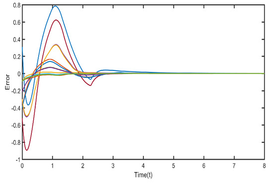
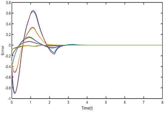
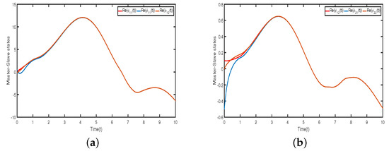
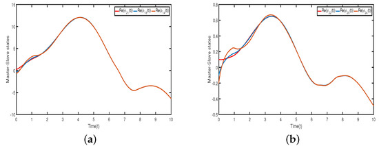
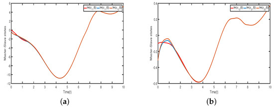
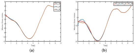
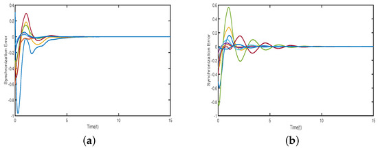
Figure 1, Figure 2, Figure 3 and Figure 4 illustrate that neurons in each cluster can synchronize with their target neurons in a finite amount of time, while under the adaptive controller, synchronization among various clusters is not achievable. Figure 5 displays the trajectories of the CS errors.
Case (ii): We consider the state of the model (23) as in the three-dimensional complex domain , that is . Then, the system parameters are must be three-dimensional and are taken as
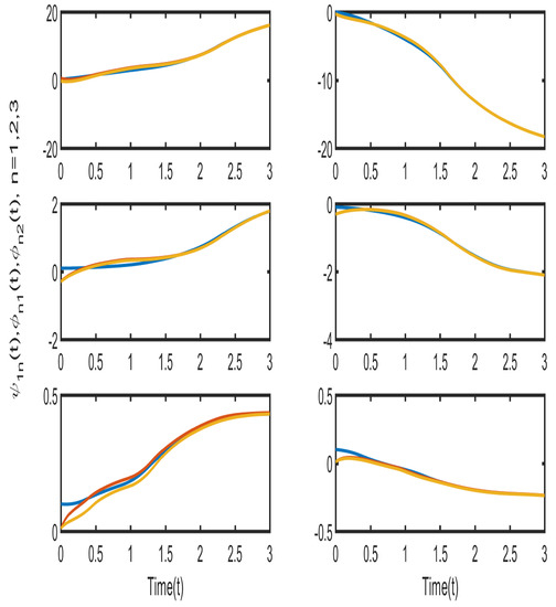
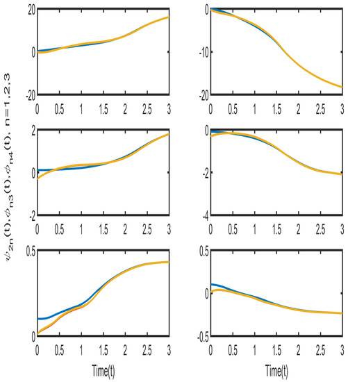
Therefore, according to the Assumptions 1–4 and Theorem 1, the conditions obtained indicate the feasible solutions are . Figure 6 and Figure 7 illustrate, that neurons in each cluster can synchronize with their target neurons in a finite amount of time, while under the adaptive controller, synchronization among various clusters is not achievable. Figure 8 and Figure 9 displays the trajectories of the CS errors.
Remark 5.
As a result, many academics have made significant efforts to study delayed neural network systems, and many excellent publications have resulted from their efforts [46,47,48,49]. For instance, the authors of [46] investigated the stability issues of neutral-type Cohen–Grossberg neural networks with multiple time delays. A novel sufficient stability criterion is derived for Cohen–Grossberg neural networks of neutral type with multiple delays by utilizing a modified and enhanced version of a previously introduced Lyapunov functional. The new stability problems for more general models of neutral-type neural network systems were investigated in [47,48]. In this study, new finite-time CS of CCVNN models with single neutral delay were realized under adaptive control. The obtained results can extend further those in the existing literature [46,47,48,49]. For further research, the dynamics of coupled delayed CVNN models with multiple neutral delays and impulsive effects will be investigated.
5. Conclusions
In this study, we examined the issue of adaptive finite-time CS pertaining to neutral-type CVCNNs with mixed time delays. The relevant stability analysis is very challenging, since it takes into account a more general dynamic model of neutral-type CVCNN with mixed time delays. A useful adaptive control scheme has been developed to address this challenging issue. Using the Lyapunov functionals approach and linear matrix inequality, the corresponding adequate conditions have been obtained. The simulation results positively indicate the viability and validity of the proposed method. For further work, finite-time CS of neutral-type delayed CVCNNs with stochastic inputs and disturbances will be studied in detail.
Author Contributions
Funding acquisition, N.B. and A.J.; Conceptualization, N.B., S.R., P.M. and A.J.; Software, N.B., S.R., P.M. and A.J.; Formal analysis, N.B., S.R., P.M. and A.J.; Methodology, N.B., S.R., P.M. and A.J.; Supervision, C.P.L.; Writing—original draft, N.B., S.R., P.M. and A.J.; Validation, N.B., S.R., P.M. and A.J.; Writing—review and editing, N.B., S.R., P.M. and A.J. All authors have read and agreed to the published version of the manuscript.
Funding
This research was supported by Rajamangala University of Technology Suvarnabhumi.
Data Availability Statement
Not applicable.
Conflicts of Interest
The authors declare no conflict of interest.
References
- Manivannan, R.; Panda, S.; Chong, K.T.; Cao, J. An Arcak-type state estimation design for time-delayed static neural networks with leakage term based on unified criteria. Neural Netw. 2018, 106, 110–126. [Google Scholar] [CrossRef] [PubMed]
- Zhou, W.; Sun, Y.; Zhang, X.; Shi, P. Cluster synchronization of coupled neural networks with Lvy noise via event-triggered pinning control. IEEE Trans. Neural Netw. Learn. Syst. 2021. [Google Scholar] [CrossRef]
- Ouyang, D.; Shao, J.; Jiang, H.; Wen, S.; Nguang, S.K. Finite-time stability of coupled impulsive neural networks with time-varying delays and saturating actuators. Neurocomputing 2021, 453, 590–598. [Google Scholar] [CrossRef]
- Zhang, K.; Zhang, H.G.; Cai, Y.; Su, R. Parallel optimal tracking control schemes for mode-dependent control of coupled Markov jump systems via integral RL method. IEEE Trans. Autom. Sci. Eng. 2019, 17, 1332–1342. [Google Scholar] [CrossRef]
- Qi, X.; Bao, H.; Cao, J. Synchronization criteria for quaternion-valued coupled neural networks with impulses. Neural Netw. 2020, 128, 150–157. [Google Scholar] [CrossRef]
- Jin, X.; Jiang, J.; Qin, J.; Zheng, W.X. Robust pinning constrained control and adaptive regulation of coupled Chuas circuit networks. IEEE Trans. Circuits Syst. I Regul Pap. 2019, 66, 3928–3940. [Google Scholar] [CrossRef]
- Ahmad, B.; Alghanmi, M.; Alsaedi, A.; Nieto, J.J. Existence and uniqueness results for a nonlinear coupled system involving Caputo fractional derivatives with a new kind of coupled boundary conditions. Appl. Math. Lett. 2021, 116, 107018. [Google Scholar] [CrossRef]
- Bannenberg, M.W.; Ciccazzo, A.; Gnther, M. Coupling of model order reduction and multirate techniques for coupled dynamical systems. Appl. Math. Lett. 2021, 112, 106780. [Google Scholar] [CrossRef]
- Li, N.; Zheng, W.X. Synchronization criteria for inertial memristor-based neural networks with linear coupling. Neural Netw. 2018, 106, 260–270. [Google Scholar] [CrossRef]
- Li, L.; Shi, X.; Liang, J. Synchronization of impulsive coupled complex-valued neural networks with delay: The matrix measure method. Neural Netw. 2019, 117, 285–294. [Google Scholar] [CrossRef]
- Tan, M.; Pan, Q. Global stability analysis of delayed complex-valued fractional-order coupled neural networks with nodes of different dimensions. Int. J. Mach. Learn. 2019, 10, 897–912. [Google Scholar] [CrossRef]
- Huang, Y.; Hou, J.; Yang, E. Passivity and synchronization of coupled reaction-diffusion complex-valued memristive neural networks. Appl. Math. Comput. 2020, 379, 125271. [Google Scholar] [CrossRef]
- Feng, L.; Hu, C.; Yu, J.; Jiang, H.; Wen, S. Fixed-time Synchronization of Coupled Memristive Complex-valued Neural Networks. Chaos Solitons Fractals 2021, 148, 110993. [Google Scholar] [CrossRef]
- Benvenuto, N.; Piazza, F. On the complex backpropagation algorithm. IEEE Trans. Signal Process. 1992, 40, 967–969. [Google Scholar] [CrossRef]
- Nitta, T. Solving the XOR problem and the detection of symmetry using a single complex-valued neuron. Neural Netw. 2003, 16, 1101–1105. [Google Scholar] [CrossRef]
- Takeda, M.; Kishigami, T. Complex neural fields with a hopfield-like energy function and an analogy to optical fields generated in phaseconjugate resonators. J. Opt. Soc. Am. 1992, 9, 2182–2191. [Google Scholar] [CrossRef]
- Jayanthi, N.; Santhakumari, R. Synchronization of time-varying time delayed neutral-type neural networks for finite-time in complex field. Math. Model. Comput. 2021, 8, 486–498. [Google Scholar] [CrossRef]
- Jayanthi, N.; Santhakumari, R. Synchronization of time invariant uncertain delayed neural networks in finite time via improved sliding mode control. Math. Model. Comput. 2021, 8, 228–240. [Google Scholar] [CrossRef]
- Zhang, W.W.; Zhang, H.; Cao, J.D.; Zhang, H.M.; Chen, D.Y. Synchronization of delayed fractional-order complex-valued neural networks with leakage delay. Phys. A 2020, 556, 124710. [Google Scholar] [CrossRef]
- Zhang, X.; Li, C.; He, Z. Cluster synchronization of delayed coupled neural networks: Delay-dependent distributed impulsive control. Neural Netw. 2021, 142, 34–43. [Google Scholar] [CrossRef]
- Gambuzza, L.V.; Frasca, M. A criterion for stability of cluster synchronization in networks with external equitable partitions. Automatica 2019, 100, 212–218. [Google Scholar] [CrossRef]
- Qin, J.; Fu, W.; Shi, Y.; Gao, H.; Kang, Y. Leader-following practical cluster synchronization for networks of generic linear systems: An event-based approach. IEEE Trans. Neural Netw. Learn. Syst. 2018, 30, 215–224. [Google Scholar] [CrossRef] [PubMed]
- Liu, P.; Zeng, Z.; Wang, J. Asymptotic and finite-time cluster synchronization of coupled fractionalorder neural networks with time delay. IEEE Trans. Neural Netw. Learn. Syst. 2020, 31, 4956–4967. [Google Scholar] [CrossRef]
- Yang, S.; Hu, C.; Yu, J.; Jiang, H. Finite-time cluster synchronization in complex-variable networks with fractional-order and nonlinear coupling. Neural Netw. 2021, 135, 212–224. [Google Scholar] [CrossRef]
- Niamsup, P.; Rajchakit, M.; Rajchakit, G. Guaranteed cost control for switched recurrent neural networks with interval time-varying delay. J. Inequalities Appl. 2013, 2013, 292. [Google Scholar] [CrossRef]
- Rajchakit, G.; Sriraman, R.; Lim, C.P.; Unyong, B. Existence, uniqueness and global stability of Clifford-valued neutral-type neural networks with time delays. Math. Comput. Simul. 2022, 201, 508–527. [Google Scholar] [CrossRef]
- Rajchakit, M.; Niamsup, P.; Rajchakit, G. A switching rule for exponential stability of switched recurrent neural networks with interval time-varying delay. Adv. Differ. Equ. 2013, 2013, 44. [Google Scholar] [CrossRef]
- Sriraman, R.; Rajchakit, G.; Lim, C.P.; Chanthorn, P.; Samidurai, R. Discrete-time stochastic quaternion-valued neural networks with time delays: An asymptotic stability analysis. Symmetry 2020, 12, 936. [Google Scholar] [CrossRef]
- Ratchagit, K. Asymptotic stability of delay-difference system of Hopfield neural networks via matrix inequalities and application. Int. J. Neural Syst. 2007, 17, 425–430. [Google Scholar] [CrossRef]
- Rajchakit, G.; Sriraman, R.; Boonsatit, N.; Hammachukiattikul, P.; Lim, C.P.; Agarwal, P. Global exponential stability of Clifford-valued neural networks with time-varying delays and impulsive effects. Adv. Differ. Equ. 2021, 2021, 208. [Google Scholar] [CrossRef]
- Rajchakit, G.; Chanthorn, P.; Niezabitowski, M.; Raja, R.; Baleanu, D.; Pratap, A. Impulsive effects on stability and passivity analysis of memristor-based fractional-order competitive neural networks. Neurocomputing 2020, 417, 290–301. [Google Scholar] [CrossRef]
- Yu, T.; Cao, J.; Huang, C. Finite-time cluster synchronization of coupled dynamical systems with impulsive effects. Discret. Contin. Dyn. Syst. Ser. B 2021, 26, 3595. [Google Scholar] [CrossRef]
- Xiao, F.; Gan, Q.; Yuan, Q. Finite-time cluster synchronization for time-varying delayed complex dynamical networks via hybrid control. Adv. Differ. Equ. 2019, 2019, 93. [Google Scholar] [CrossRef]
- He, J.J.; Lin, Y.Q.; Ge, M.F.; Liang, C.D.; Ding, T.F.; Wang, L. Adaptive finite-time cluster synchronization of neutral-type coupled neural networks with mixed delays. Neurocomputing 2020, 384, 11–20. [Google Scholar] [CrossRef]
- Tang, R.; Yang, X.; Wan, X. Finite-time cluster synchronization for a class of fuzzy cellular neural networks via non-chattering quantized controllers. Neural Netw. 2019, 113, 79–90. [Google Scholar] [CrossRef] [PubMed]
- Ding, D.; Wang, Z.; Han, Q.L. Neural-network-based output-feedback control with stochastic communication protocols. Automatica 2019, 106, 221–229. [Google Scholar] [CrossRef]
- He, W.; Du, W.; Qian, F.; Cao, J. Synchronization analysis of heterogeneous dynamical networks. Neurocomputing 2013, 104, 146–154. [Google Scholar] [CrossRef]
- Wang, L.; Zeng, Z.; Ge, M.F. A disturbance rejection framework for finite time and fixed-time stabilization of delayed memristive neural networks. IEEE Trans. Syst. Man Cybern. Syst. 2019, 51, 905–915. [Google Scholar] [CrossRef]
- Wu, H.; Li, R.; Zhang, X.; Yao, R. Adaptive finite-time complete periodic synchronization of memristive neural networks with time delays. Neural Process. Lett. 2015, 42, 563–583. [Google Scholar] [CrossRef]
- Yang, C.; Huang, L.; Cai, Z. Fixed-time synchronization of coupled memristor-based neural networks with time-varying delays. Neural Netw. 2019, 116, 101–109. [Google Scholar] [CrossRef]
- Wang, Z.; Liu, H.; Shen, B.; Alsaadi, F.E.; Dobaie, A.M. H∞ state estimation for discrete-time stochastic memristive BAM neural networks with mixed time-delays. Int. J. Mach. Learn. Cybern. 2019, 10, 771–785. [Google Scholar] [CrossRef]
- Wang, K.; Teng, Z.; Jiang, H. Adaptive synchronization of neural networks with time-varying delay and distributed delay. Phys. A 2008, 387, 631–642. [Google Scholar] [CrossRef]
- Wu, H.; Zhang, X.; Li, R.; Yao, R. Finite-time synchronization of chaotic neural networks with mixed time-varying delays and stochastic disturbance. Memetic Comput. 2015, 7, 231–240. [Google Scholar] [CrossRef]
- Chanthorn, P.; Rajchakit, G.; Ramalingam, S.; Lim, C.P.; Ramachandran, R. Robust dissipativity analysis of hopfield-type complex-valued neural networks with time-varying delays and linear fractional uncertainties. Mathematics 2020, 8, 595. [Google Scholar] [CrossRef]
- Chanthorn, P.; Rajchakit, G.; Humphries, U.; Kaewmesri, P.; Sriraman, R.; Lim, C.P. A delay-dividing approach to robust stability of uncertain stochastic complex-valued hopfield delayed neural networks. Symmetry 2020, 12, 683. [Google Scholar] [CrossRef]
- Faydasicok, O. An improved Lyapunov functional with application to stability of Cohen–Grossberg neural networks of neutral-type with multiple delays. Neural Netw. 2020, 132, 532–539. [Google Scholar] [CrossRef]
- Arik, S. New criteria for stability of neutral-type neural networks with multiple time delays. IEEE Trans. Neural Netw. Learn. Syst. 2019, 31, 1504–1513. [Google Scholar] [CrossRef]
- Akca, H.; Covachev, V.; Covacheva, Z. Global asymptotic stability of Cohen-Grossberg neural networks of neutral type. J. Math. Sci. 2015, 205, 719–732. [Google Scholar] [CrossRef]
- Arik, S. An analysis of stability of neutral-type neural systems with constant time delays. J. Frankl. Inst. 2014, 351, 4949–4959. [Google Scholar] [CrossRef]
Publisher’s Note: MDPI stays neutral with regard to jurisdictional claims in published maps and institutional affiliations. |
© 2022 by the authors. Licensee MDPI, Basel, Switzerland. This article is an open access article distributed under the terms and conditions of the Creative Commons Attribution (CC BY) license (https://creativecommons.org/licenses/by/4.0/).
