
Cyclic Mobilisation of Soil–Structure Interface in the Framework of Fractional Plasticity


Abstract
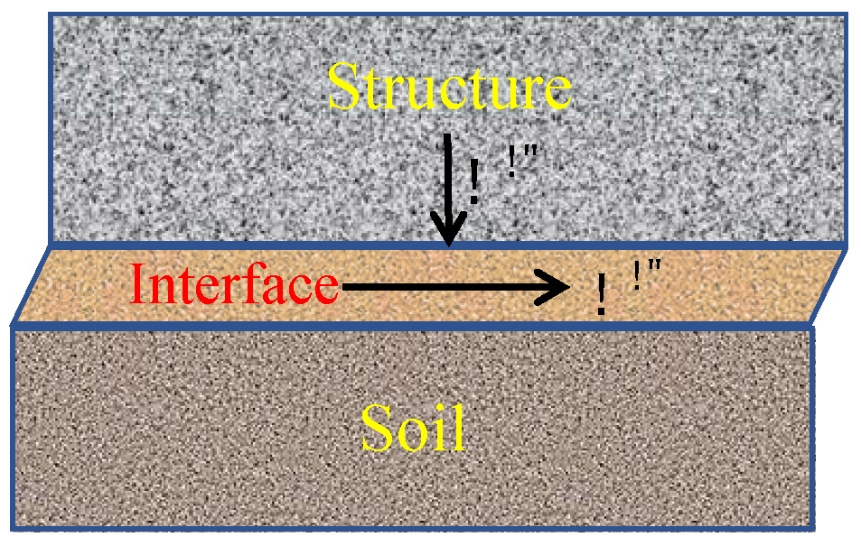
:1. Introduction
2. Constitutive Model in the Framework of Fractional Plasticity
2.1. Constitutive Relation
2.2. Model Development
2.3. Model Constants
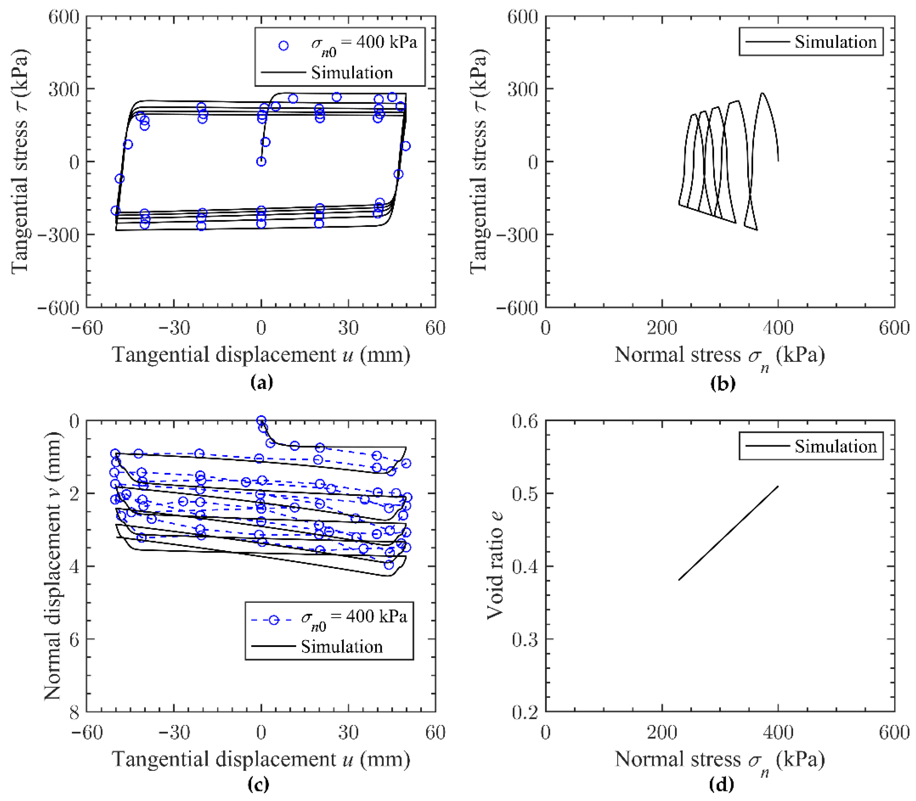
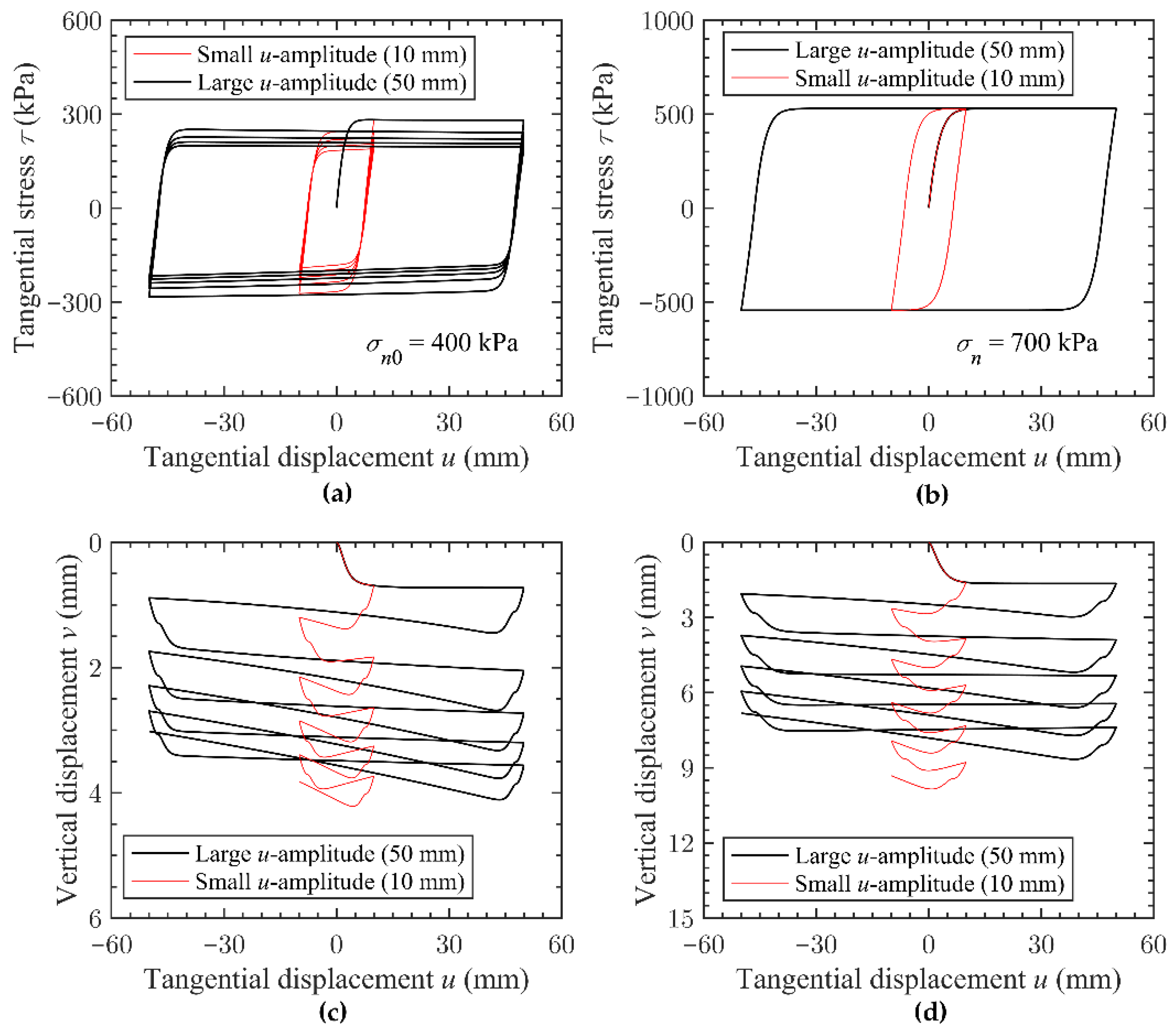
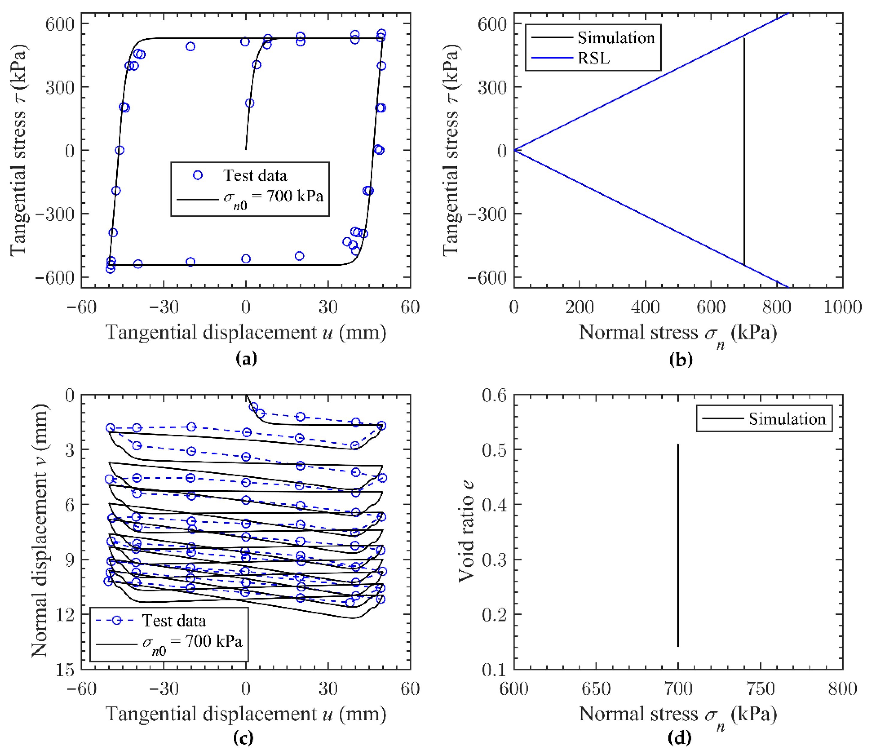
3. Numerical Simulations and Discussions
4. Conclusions
- (a)
- Without using an additional plastic potential function, the method developed can consider the nonassociated plastic flow response of the soil–structure interface by using fractional order derivatives of the plastic yielding function.
- (b)
- By incorporating the effect of material state and soil fabric on the plastic response of the soil–structure interface, a fabric-enriched state-dependent fractional stress-dilatancy equation and a state-dependent hardening modulus were suggested.
- (c)
- The developed model contained eleven parameters, which can be all determined from laboratory test results. Numerical simulations of cyclic mobilisation of the Zipingpu rockfill–steel interface revealed that the model can characterise the mobilised strength and displacement of the soil–structure interface under different boundary conditions in a reasonable manner.
- (d)
- The variations of tangential stress and void ratio with the normal stress were different under CNS and CNL conditions. The strength of the interface under CNS conditions reduced with the number of load cycles. As the displacement amplitude increased, the extent of the strength reduction decreased. However, displacement amplitude had a limited impact on strength mobilisation of the interface under CNL.
- (e)
- The current model can only simulate the two-dimensional stress-displacement of the soil–structure interface. Further work on developing a multiaxial fractional plastic model for capturing the true three-dimensional response of the interface needs to be carried out.
Author Contributions
Funding
Institutional Review Board Statement
Informed Consent Statement
Data Availability Statement
Acknowledgments
Conflicts of Interest
References
- Raheem, S.A.; Hayashikawa, T.; Hashimoto, I. Effects of soil–foundation–superstructure interaction on seismic response of cable-stayed bridges tower with spread footing foundation. J. Struct. Eng. 2003, 49, 475–486. [Google Scholar]
- Zaman, M.M.; Desai, C.S.; Drumm, E.C. Interface model for dynamic soil-structure interaction. J. Geotech. Eng. 1984, 110, 1257–1273. [Google Scholar] [CrossRef]
- Desai, C.S. Mechanics of Materials and Interfaces: The Disturbed State Concept; CRC Press: Boca Raton, FL, USA, 2000. [Google Scholar]
- Kamura, A.; Kazama, M. Assessment of stiffness degradation of soil by in-situ cyclic loading using pressuremeter. In Proceedings of the 6th International Conference on Geotechnical and Geophysical Site Characterization, Budapest, Hungary, 26–29 September 2021. [Google Scholar]
- Gao, Y.; Zhang, N.; Li, D.; Liu, H.; Cai, Y.; Wu, Y. Effects of topographic amplification induced by a U-Shaped canyon on seismic waves. Bull. Seismol. Soc. Am. 2012, 102, 1748–1763. [Google Scholar] [CrossRef]
- Zhang, N.; Gao, Y.; Cai, Y.; Li, D.; Wu, Y. Scattering of SH waves induced by a non-symmetrical V-shaped canyon. Geophys. J. Int. 2012, 191, 243–256. [Google Scholar] [CrossRef] [Green Version]
- Gao, Y.; Wu, Y.; Li, D.; Liu, H.; Zhang, N. An improved approximation for the spectral representation method in the simulation of spatially varying ground motions. Probabilistic Eng. Mech. 2012, 29, 7–15. [Google Scholar] [CrossRef]
- Gao, Y.; Wu, Y.; Cai, Y.; Liu, H.; Li, D.; Zhang, N. Error assessment for spectral representation method in random field simulation. J. Eng. Mech. 2012, 138, 711–715. [Google Scholar] [CrossRef]
- Maghsoodi, S.; Cuisinier, O.; Masrouri, F. Non-isothermal soil-structure interface model based on critical state theory. Acta Geotech. 2021, 16, 2049–2069. [Google Scholar] [CrossRef]
- Kishida, H.; Uesugi, M. Tests of the interface between sand and steel in the simple shear apparatus. Géotechnique 1987, 37, 45–52. [Google Scholar] [CrossRef]
- Zhang, G.; Zhang, J. Monotonic and cyclic tests of interface between structure and gravelly soil. Soils Found. 2006, 46, 505–518. [Google Scholar] [CrossRef] [Green Version]
- Martinez, A.; Frost, J.D. Undrained behavior of sand–structure interfaces subjected to cyclic torsional shearing. J. Geotech. Geoenviron. Eng. 2018, 144, 04018063. [Google Scholar] [CrossRef]
- Wang, H.; Zhou, W.; Yin, Z.; Jie, X. Effect of grain size distribution of sandy soil on shearing behaviors at soil–structure interface. J. Mater. Civ. Eng. 2019, 31, 04019238. [Google Scholar] [CrossRef]
- Grabowski, A.; Nitka, M.; Tejchman, J. 3D DEM simulations of monotonic interface behaviour between cohesionless sand and rigid wall of different roughness. Acta Geotech. 2021, 16, 1001–1026. [Google Scholar] [CrossRef]
- Lashkari, A.; Jamali, V. Global and local sand–geosynthetic interface behaviour. Géotechnique 2021, 71, 346–367. [Google Scholar] [CrossRef]
- Wang, R.; Dafalias, Y.F.; Fu, P.; Zhang, J.M. Fabric evolution and dilatancy within anisotropic critical state theory guided and validated by DEM. Int. J. Solids Struct. 2019, 188–189, 210–222. [Google Scholar] [CrossRef] [Green Version]
- Zhang, F.; Gao, Y.; Leshchinsky, D.; Yang, S.; Dai, G. 3D effects of turning corner on stability of geosynthetic-reinforced soil structures. Geotext. Geomembr. 2018, 46, 367–376. [Google Scholar] [CrossRef]
- Sun, Y.; Sumelka, W.; Gao, Y. Reformulated fractional plasticity for soil-structure interface. Mech. Res. Commun. 2020, 108, 103580. [Google Scholar] [CrossRef]
- Saberi, M.; Annan, C.D.; Konrad, J.M. A unified constitutive model for simulating stress-path dependency of sandy and gravelly soil–structure interfaces. Int. J. Non-Linear Mech. 2018, 102, 1–13. [Google Scholar] [CrossRef]
- Stutz, H.; Mašín, D. Hypoplastic interface models for fine-grained soils. Int. J. Numer. Anal. Meth. Geomech. 2017, 41, 284–303. [Google Scholar] [CrossRef]
- Sun, Y.; Gao, Y.; Zhu, Q. Fractional order plasticity modelling of state-dependent behaviour of granular soils without using plastic potential. Int. J. Plast. 2018, 102, 53–69. [Google Scholar] [CrossRef]
- Sun, Y.; Sumelka, W. Multiaxial stress-fractional plasticity model for anisotropically overconsolidated clay. Int. J. Mech. Sci. 2021, 205, 106598. [Google Scholar] [CrossRef]
- Sun, Y.; Sumelka, W.; Gao, Y.; Nimbalkar, S. Phenomenological fractional-order stress-dilatancy model for granular soil and soil-structure interface under monotonic and cyclic loads. Acta Geotech. 2021, 16, 3115–3132. [Google Scholar] [CrossRef]
- Sun, Y.; Gao, Y.; Song, S.; Chen, C. Three-dimensional state-dependent fractional plasticity model for soils. Int. J. Geomech. 2020, 20, 04019161. [Google Scholar] [CrossRef]
- Lu, D.; Liang, J.; Du, X.; Ma, C.; Gao, Z. Fractional elastoplastic constitutive model for soils based on a novel 3D fractional plastic flow rule. Comput. Geotech. 2019, 105, 277–290. [Google Scholar] [CrossRef] [Green Version]
- Lu, D.; Zhou, X.; Du, X.; Wang, G. A 3D fractional elastoplastic constitutive model for concrete material. Int. J. Solids Struct. 2019, 165, 160–175. [Google Scholar] [CrossRef]
- Sun, Y.; Sumelka, W.; Gao, Y. Bounding surface plasticity for sand using fractional flow rule and modified critical state line. Arch. Appl. Mech. 2020, 90, 2561–2577. [Google Scholar] [CrossRef]
- Dafalias, Y.F.; Manzari, M.T. Simple plasticity sand model accounting for fabric change effects. J. Eng. Mech. 2004, 130, 622–634. [Google Scholar] [CrossRef]
- Yang, J.; Yin, Z.Y. Soil-structure interface modeling with the nonlinear incremental approach. Int. J. Numer. Anal. Meth. Geomech. 2021, 45, 1381–1404. [Google Scholar] [CrossRef]


| tn | M | |||||||||
|---|---|---|---|---|---|---|---|---|---|---|
| 5d50 | 41 | 35 | 0.777 | 0.548 | 0.0437 | 1 | 6 | 0.46 | 1.3 | 0.01 |
Publisher’s Note: MDPI stays neutral with regard to jurisdictional claims in published maps and institutional affiliations. |
© 2022 by the authors. Licensee MDPI, Basel, Switzerland. This article is an open access article distributed under the terms and conditions of the Creative Commons Attribution (CC BY) license (https://creativecommons.org/licenses/by/4.0/).
Share and Cite
Xu, J.; Shen, Y.; Sun, Y. Cyclic Mobilisation of Soil–Structure Interface in the Framework of Fractional Plasticity. Fractal Fract. 2022, 6, 76. https://doi.org/10.3390/fractalfract6020076
Xu J, Shen Y, Sun Y. Cyclic Mobilisation of Soil–Structure Interface in the Framework of Fractional Plasticity. Fractal and Fractional. 2022; 6(2):76. https://doi.org/10.3390/fractalfract6020076
Chicago/Turabian StyleXu, Junhong, Yang Shen, and Yifei Sun. 2022. "Cyclic Mobilisation of Soil–Structure Interface in the Framework of Fractional Plasticity" Fractal and Fractional 6, no. 2: 76. https://doi.org/10.3390/fractalfract6020076
APA StyleXu, J., Shen, Y., & Sun, Y. (2022). Cyclic Mobilisation of Soil–Structure Interface in the Framework of Fractional Plasticity. Fractal and Fractional, 6(2), 76. https://doi.org/10.3390/fractalfract6020076