Article

May the Piezoresistivity of GNP-Modified Cement Mortar Be Related to Its Fractal Structure?

College of Civil Engineering and Architecture, Zhejiang University, Hangzhou 310058, China
*
Authors to whom correspondence should be addressed.
Fractal Fract. 2021, 5(4), 148; https://doi.org/10.3390/fractalfract5040148
Submission received: 24 August 2021 / Revised: 15 September 2021 / Accepted: 25 September 2021 / Published: 30 September 2021
(This article belongs to the Special Issue Fractal and Fractional in Cement-based Materials)

Abstract

:
High piezoresistivity of cement-based composites tuned by conductible fillers provides a feasible way to develop self-sensing smart structures and buildings. However, the microstructural mechanisms remain to be properly understood. In the present work, the piezoresistivity of cement mortar with different dosages of graphene nanoplatelets (GNPs) was investigated, and the microstructure was assessed by electron scanning microscopy (SEM) and mercury intrusion porosimetry (MIP). Two surface fractal models were introduced to interpret the MIP data to explore the multi-scale fractal structure of the GNP-modified cement mortars. Results show that the incorporation of GNPs into cement mortar can roughen the fracture surfaces due to the GNPs’ agglomeration. Gauge factor (GF) rises and falls as GNP content increases from 0% to 1% with the optimal piezoresistivity observed at GNP = 0.1% and 0.05%. The GF values of the optimum mortar are over 50 times higher than those of the reference mortar. Fractal dimensions in macro and micro fractal regions change with GNP content. Analysis shows that the fractal dimensions in micro region decrease first and then increase with the increase of GF values. GNPs not only impact the fractal structure of cement mortar, but also alter the tunneling and contact effects that govern the piezoresistivity of composite materials.

1. Introduction

Highly piezoresistive cement-based materials (CBMs) are urgently needed for the development of self-sensing smart structures and buildings. A general way to tune the piezoresistive properties, as well as the mechanical properties and microstructure of CBMs is incorporating conductible fillers into the material matrix, as this route shows the feature of ease to fabrication and control [1,2,3]. Graphene-based nano fillers (GBNFs) may be a preferable candidate to tune both the piezoresistive and mechanical properties of cement-based materials due to its many excellent physical properties, such as mechanical properties [4], thermal-electric performance [5] and carrier mobility [6].
Depending on the derivatives of graphene, different GBNFs are chosen for new cement composite development [7,8,9]. Graphene oxide (GO) and graphene nanoplatelets (GNPs) may be two of the most widely used GBNFs to tune the material properties of CBMs [10,11]. Compared with GO, that is widely used to enhance the mechanical properties of CBMs due to its stronger surface actions [12,13,14], GNPs that are composed of several layers of graphene with the diameter of several microns and thickness of less than 100 nanometers shows benefits to enhance the electrical properties of CBMs owing to its high electrical conductivity [15]. The improvement in the mechanical properties of CBMs by GBNFs is generally attributed to the enhanced cement hydration, tightly packed, and uniformly distributed hydration crystals, and decreased or eliminated cracks and flaws of the material matrix [16]. However, these effects may be counterbalanced by the raised flaws of the agglomerations of GBNFs, so strength may decrease at high GBNF dosages [17,18]. The optimal contents of GNPs for strength enhancements are reported in relatively broad intervals (10.8~83.7%) [19,20,21]. Similar trends are reported for the piezeresistivity of CBMs with GNPs [22]. However, the high content of GNPs in the cement matrix will lead to the decrease of piezoresistive performances, which limits the application of GNPs for developing self-sensing structural materials. Our previous work suggested that when GNP content is too high, the conductive paths are completely connected and the piezoresistive performance is not improved any more [23].
Both the mechanical and piezoresistive properties of CBMs blended with GBNFs are intimately associated with their microstructure that shows extreme complexity and heterogeneity [24]. For example, the pores in cement composites possess the broad ranges from nanometer (hydrated calcium silicate, C-S-H and inter-particle pores) to millimeter (residual air voids) [25]. Therefore, the quantitative characterization of the microstructure of CBMs remains facing big challenges at present. Fractal theories may provide preferable solutions to address complex structures of materials [26,27]
According to the fractal theories, an object showing the structure with self-similarity in certain scales may be characterized by a non-integer value, named fractal dimensions [28,29,30,31]. Due to the clear physical meanings, and elegant and simple expression, at present, various fractal theory-based models were developed to interpret the microstructure/pore structure data obtained by different test methods, including nitrogen adsorption/desorption [32,33,34], mercury intrusion porosimetry (MIP) [35,36,37], small-angle scattering of X-rays (SAXS) or neutrons (SANS) [38,39,40], nuclear magnetic resonance (NMR) [41], and scanning electronic microscopy (SEM) [42]. Meanwhile, great efforts were made to establish quantitative links between fractal dimensions and macro properties [43,44,45,46,47]. Niu et al. [43] suggested that the microstructural complexity indexed by fractal dimensions can directly reflect the mechanical properties of concrete. The appealing relationships between fractal dimensions and macro properties (e.g., strength, permeability, and chloride diffusivity) of CBMs imply that fractal theories can narrow the gaps between complex material structure and various macro properties [25,27,48,49]. Given the debates on the structural associations to the piezoresistivity of cement composites blended with GBNFs, it thus provides great incentives to clarify the relationships between the fractal structure and piezoresistive behaviors of cement composites.
The aim of this work was to explore the relationships between piezoresistive properties of GNP-modified cement mortar and the fractal characteristics measured by MIP. To this end, cement composites with five different GNP contents (0%, 0.05%, 0.1%, 0.5% and 1%) were fabricated, and the fractional changes in resistivity (FCRs) and GFs were measured to assess the piezoresistive behaviors under compression tests. Two fractal models were employed to evaluate the fractal characteristics of the GNP-modified cement composites from the pore structure data by MIP tests. The fractal dimension-gauge factor relationships were reported and the piezoresistive mechanisms were discussed.

2. Materials and Methods

2.1. Materials

A Portland cement in the type of PI 42.5 was adopted as the binding material. The chemical compositions and main minerals provided by the producer are listed in Table 1, where CaO, SiO2, Al2O3, and Fe2O3 are the components with the highest proportions, and the minerals of C3S, C2S, C3A, and C4AF occupy 94% of the total mass. The density and specific surface area of the cement are 3.1 g/mL and 3450 cm2/g. A natural quartz sand with silica (SiO2) content ≥96% and the fineness modulus of 2.6 was used as the aggregate. GNPs powder with a purity >99.5% was purchased from XFNANO Materials Co., Ltd. (Nanjing, China). The GNPs powder shows the mean diameter of 5–10 μm, thickness of 3–10 nm, specific surface area of 31.657 m2/g, tap density of 0.075 g/mL, apparent density of 0.05 g/mL, and electrical conductivity of 500–1000 S/cm.

2.2. Specimen Preparation

The dispersion of nano fillers can greatly impact the macro properties of cement composites [50], so controls of GNPs dispersion were first tested. A melamine-based dispersant was selected to disperse the GNPs powder due to its higher dispersion efficiency and stabilization on the exfoliated GNPs suspension than polycarboxylic acid and naphthalene sulfonate dispersants according to our previous data [31]. The stably dispersed GNP suspension was prepared as follows: first, the melamine-based dispersant was dissolved into water to prepare the dispersant solution. Later, the GNP powder was mixed with the dispersant solution, and experienced ultrasonic stirrings (CS5000D 20 kHz, Jiekang, Shenzhen, China) for 5 min followed by a water bath cooling for another 5 min. The process was repeated three times in total to achieve the homogeneously dispersed GNP suspension. After that, the GNP suspension was settled for 4 h to check its stabilization. Our tests showed that no sediments occurred to the prepared GNPs suspension, suggesting the good dispersion efficiency and stabilization (Figure 1).
The solid raw materials (cement and sand) and the homogeneously dispersed GNPs suspension were mixed together according to the mixing proportions shown in Table 2. Low speed stirrings for 180 s and high speed stirrings for 30 s were employed to prepare the homogeneous mortar slurries (Figure 1). Five levels of GNP contents were designed, namely, 0%, 0.05%, 0.1%, 0.5% and 1% by cement weight. The cement mortar specimens were then labeled as CM-GNPX (X = percentages of GNPs) (Table 2).
The homogenously mixed mortar slurries were cast into cuboid steel molds in 40 × 40 × 160 mm3. Vibrations were performed for 30 s to remove the air bubbles entrapped in the slurries. A total of 4 copper electrodes in 40 × 60 mm2 were embedded in the set positions of each mortar. The specific geometric configuration of the copper electrodes is shown in Figure 2. After that, plastic films were used to seal all specimens to avoid the possible moisture loss at early curing ages. After primary curing for 24 h, the specimens were demoulded and gently removed into a curing chamber for standard curing (temperature of 20 °C and relative humidity > 95%) until next tests.
After 28 d curing, all the specimens were oven dried at 60 °C for 48 h to remove the capillary water. Then the exposed parts of the copper electrodes were wrapped with conductive tape and connected with clips to decrease the impacts of contact resistance. The circuit of the four-probe piezoresistive tests is shown in Figure 2.

2.3. Experiments and Methods

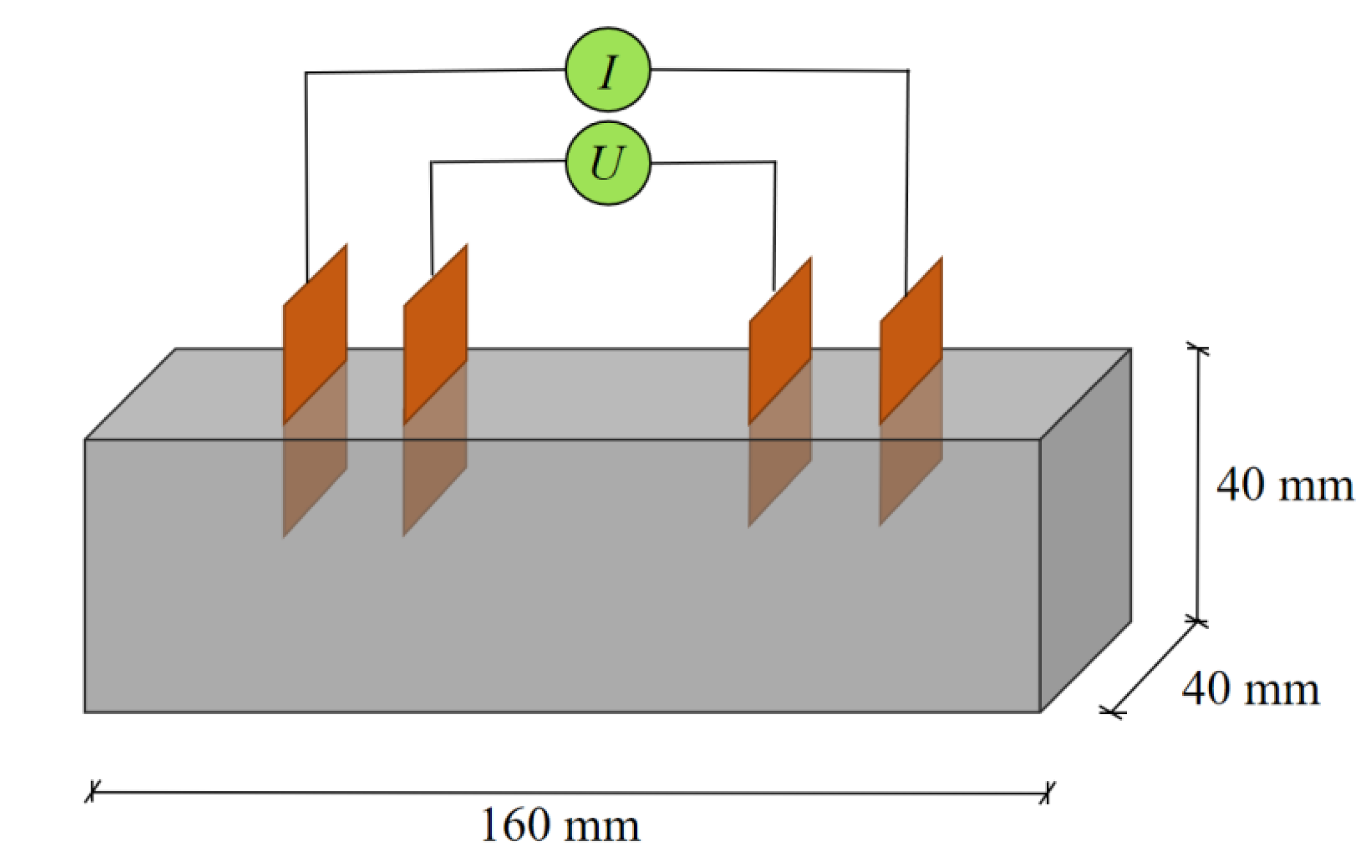
2.3.1. Piezoresistive Test

When all the arrangements of the four-probe piezoresistive tests were readily prepared, the specimens were fixed on the loading frame of an INSTRON high-accurate mechanical testing machine (Type 8820, Intrusion, Plano, TX, USA). A triangular-wave loading scheme (from 0 to 30 kN) was designed. As the loads rose and fell for three cycles, the specimens experienced recycled compression stresses between 0 to 18.75 MPa, and the signals of electrical resistance were recorded.
Fractional resistance change(FCR), R/R0, was adopted to assess the relative changes of electrical resistance of the specimens during cyclic loads. A sensitivity index, gauge factor (GF = (∆R/R0)/ε), with ε standing for the stains under external loads), is used to evaluate the piezoresistivity of the GNPs-modified cement mortars at low strains [51,52].

2.3.2. MIP Test

MIP tests were carried out in a device of Autopore IV 9510 (Micromeritics Instrument Corporation, Norcross, GA, USA). The samples for MIP tests were collected from the central part of each undamaged cement mortar, and dried in an oven at 60 °C for 24 h to remove the physically confined water. The intrusion pressure was gradually increased from 0.54 psi (3.7 kPa) to 60,000 psi (414 MPa) with each pressure step for 10 s. To obtain the pore size data, cylindrical pores with the mercury-substrate contact angle of 130 degrees and the surface tension between vapor and liquid mercury of 485 N/m were adopted.

2.3.3. SEM Test

The micro-morphology of GNP-modified cement mortars was analyzed by FEI Quanta FEG650 field emission SEM (ThermoFisher, Hillsboro, OR, USA). Samples with the size around 10 mm were also prepared from crushed cement mortar. No surface polishing was applied to preserve the original morphology of the fractured surfaces. The acceleration voltages of 20 kV, spot line of 3 nm and the working distances of 10~15 mm were set for all SEM tests.

2.3.4. Fractal Models

The pore structure data by MIP tests were interpreted by Neimark’s model (N-model) and Zhang’s model (Z-model) that both start from the energy conservation [53,54]. For the N-model, the surface areas can be estimated as [53]:
S = 1 γ cos θ 0 V p P d V
where γ is the surface tension of mercury and θ is the contact angle between mercury and pore surface; P and V represent the mercury intrusion pressure and volume, respectively.
For simplification, pores are idealized as cylindrical tubes with different radii. Pfeifer and Avnir [55] pointed out that the necessary and sufficient condition of internal pore surface with fractal characteristics is:
d V d r r 2 D
where r represents the pore radius, D represents the fractal dimensions (2 ≤ D < 3). The mercury intrusion pressure, P and the minimum pore diameter, r, that mercury can reach, can be related by the Washburn equation,
P = 2 γ cos θ r .
Substituting Equations (2) and (3) into Equation (1), the logarithmic proportional relationship between the pore inner surface and the invasion pressure is obtained (identical to the N-model):
log ( S ) ( D 2 ) log ( P )
Considering the same energy regime of mercury intrusion in porous materials, Zhang and Li [56] put forward the logarithmic ratio between cumulative intrusion, Wn, and cumulative mercury intrusion surface, Qn, which can be expressed as:
ln ( W n ) = C + ln ( Q n )
where C is a constant and n represents an invasion stage. In each invasion stage, the invasion work, Wn, and the invasion parameter, Qn, can be expressed as:
W n = i = 1 n P i Δ V i
Q n = r n 2 D V n D / 3
The substitution of Equations (6) and (7) into Equation (5), and the fractal dimensions, D, can be obtained as the slope of Wn/rn2 and Vn1/3/rn [57]:
ln ( W n r n 2 ) = D ln ( V n 1 / 3 r n ) + C
Equation (8) is identical to the Z-model for fractal dimensions calculation.

3. Results and Discussions

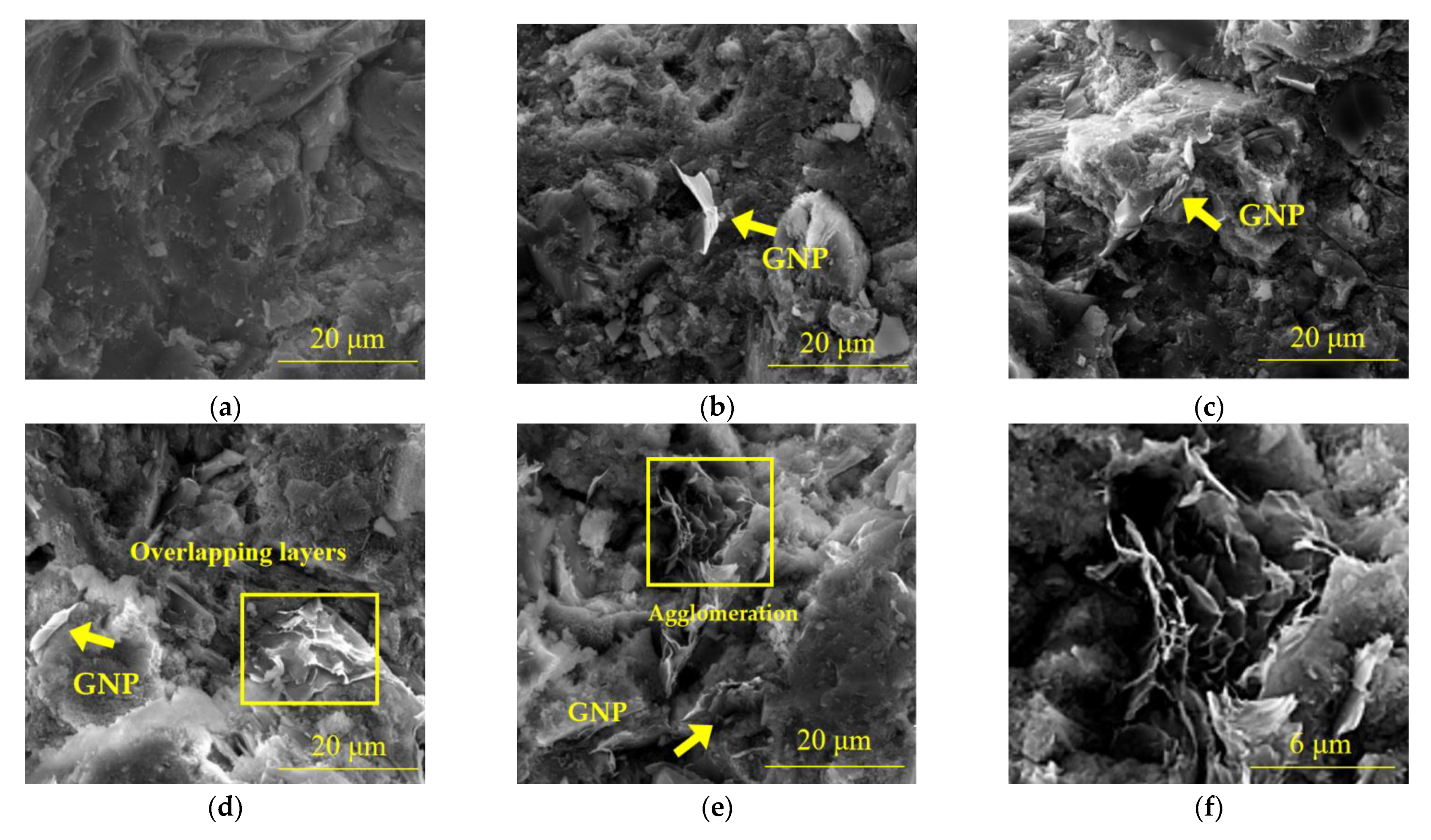
3.1. SEM Characteristics

SEM micro-morphology characteristics are shown in Figure 3. For CM-GNP0, cement hydration products closely compact together, forming a dense cement matrix, so relatively flat fracture surfaces can be observed (Figure 3a). When GNPs are incorporated into the cement mortar, the fracture surfaces become much rougher. At low GNP content, i.e., CM-GNP0.05, GNPs are wrapped by cement hydration products without agglomerations (Figure 3b). However, with the increase of GNP content, more GNPs can be observed on the fractured surfaces (Figure 3c), and multi-layer GNPs may be overlapped to form GNP corrugations (Figure 3d). For CM-GNP1, the agglomeration of GNPs becomes a porous graphene coacervate (Figure 3e,f). This porous structure of large GNP agglomerations would certainly bring a negative effect on the mechanical properties of CBMs [58] but may have benefits to build tunnels for electron transport [23]. The roughness enhancement in fracture surfaces of cement composites with GBNFs is reported elsewhere [59].

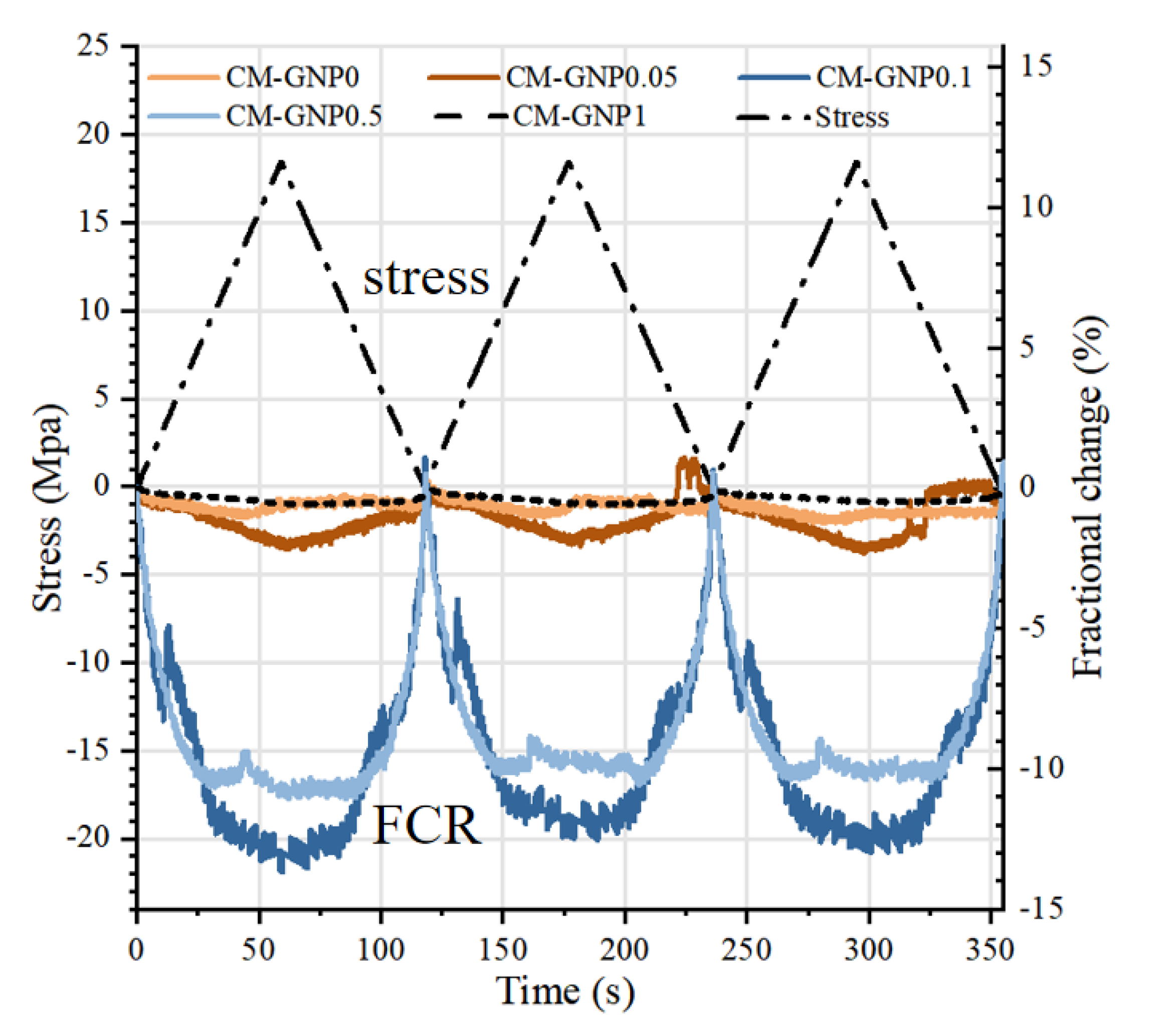
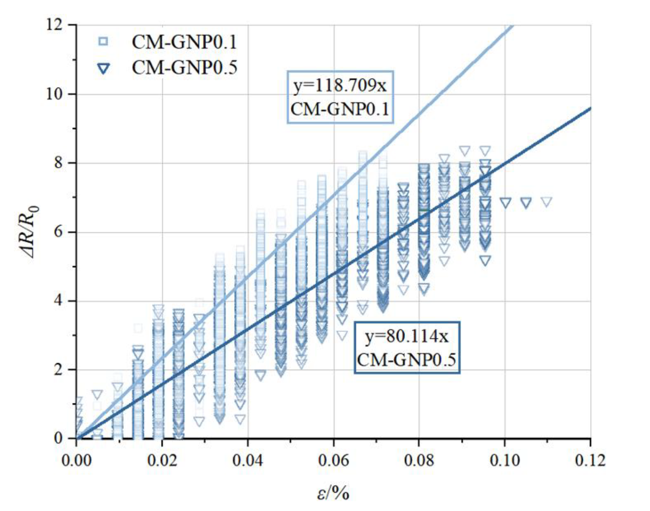
3.2. Piezoresistive Behaviors

The variations of fractional changes in electrical resistivity and axial stress under cyclic compression loading for different GNP-modified cement composites are illustrated in Figure 4. Generally, under cyclic compression loading, the negative FCR values are obtained due to the shortages in conductive paths. Apparently, the insignificant FCR values are observed in the CM-GNP0, CM-GNP0.05 and CM-GNP1 samples. At the middle GNP contents, the FCR curves of GNP-modified cement mortars become more obvious. For the samples with 0.1% and 0.5% GNP contents (CM-GNP0.1 and CM-GNP0.5), the FCR values become to −10~−12%/MPa. The similar FCR values of CBM modified with fillers are reported elsewhere [60,61].
The plots of specific FCR data against the axial strain for all the GNP-modified cement mortar specimens are presented in Figure 5, Figure 6 and Figure 7, and the statistical chart of the slopes (identical to the GF values) is shown in Figure 8. Roughly, the FCR-strain plots conform to a linear form (Figure 5, Figure 6 and Figure 7), and the CM-GNP0.1 and CM-GNP0.5 samples show relatively good correlations between the resistivity changes and the deformation changes (Figure 6). It is noteworthy that, at the beginning of strains, the huge data variability appears, which may be caused by the insufficient initial contact between the probes and cement matrix [23].
GF values show great sensitivity to GNP contents. At low GNP contents, i.e., CM-GNP0 and CM-GNP0.01, as shown in Figure 5, the GF values are relatively low (GF = 2.336 and 7.799, respectively). At such low contents of conductible fillers, the tunnel effect [62] may play a part but has a limited effect on the increases of GF values. As the GNP content increases (i.e., CM-GNP0.05 and CM-GNP0.1, shown in Figure 6), the GF values increase by more than one order of magnitude (GF = 118.709 and 80.114, respectively). In proper filler contents, GNPs can form a semi-conductive grid in cement matrix [63,64]. The optimal GF values of the GNP-modified cement mortars are higher than the values reported elsewhere (35–55.3) [65,66,67]. Different carbon derivatives and dispersion methods used in the literature may account for the GF differences. For example, the relative plate surfaces of GO particles used in [67] may reduce the contact possibilities for the samples under mechanical loads, so the GF values are lower than that of GNP-modified cement mortar, where the high irregular corrugations of GNPs provide more contact surfaces during piezoresistive tests [23].However, when the GNP content is too high, the completely conductive grid is formed and the electrical resistance will not change obviously under external loads. As shown in Figure 7, the GF values of CM-GNP1 are reduced heavily to 4.127.

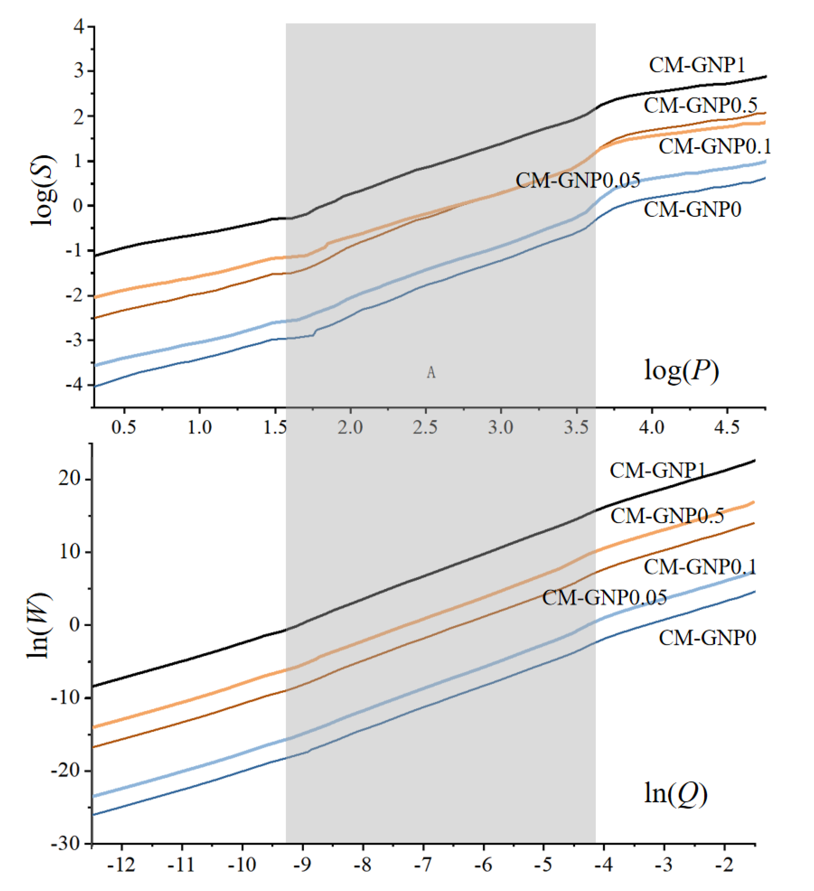
3.3. Fractal Dimensions and Fractal Regions

Fractal plots were performed to the MIP data (Figure 9) to obtain the fractal characteristics. In Figure 9, only the linear parts with the slopes between 2 and 3 are adopted as the fractal regions, whereas those with the slopes over 3 or less than 2 (the shadowed areas in Figure 9) are discarded due to the loss of physical meanings [28]. The specific fractal characteristics calculated from the N-model (DN) and Z-model (DZ) are presented in Table 3 and Table 4. It shows that the fractal dimensions evaluated by the Z-model are systematically smaller than those by the N-model, which is attributed to the intrinsic physical differences between the two models. Similar findings are reported elsewhere [68].
To clearly illustrate the scale dependence of fractal properties, all fractal regions are presented in Figure 10. Measured by pore range, fractal region I corresponds roughly to the capillary pores, resulted from the unfilled space of hydration products. Region III can be related to the inter-layer or inter-granular pores of the hydration product C-S-H of cement. In the classic C-S-H model, these C-S-H gels form a ‘globule’, having an intrinsic gap of about 2.2 nm and then these globules assemble together to form C-S-H solid, having an intrinsic granular gap of about 5.6 nm [25]. However, for the transition region II, the pore size falls into the smaller capillary pore range, of which the surface is more related to other hydrates than C-S-H [69]. Interestingly, the values of DN in region III are close to the fractal dimensions of cauliflower (D = 2.80), while those of DZ are approaching the fractal dimensions of Apollonian spheres (D = 2.474) (Table 3 and Table 4). However, the findings do not indicate that the microstructure of cement mortars follows the Apollonian spheres compaction structure or the cauliflower structure, because fractal dimensions cannot uniquely define a pore-solid structure of a material with complex microstructure [70].

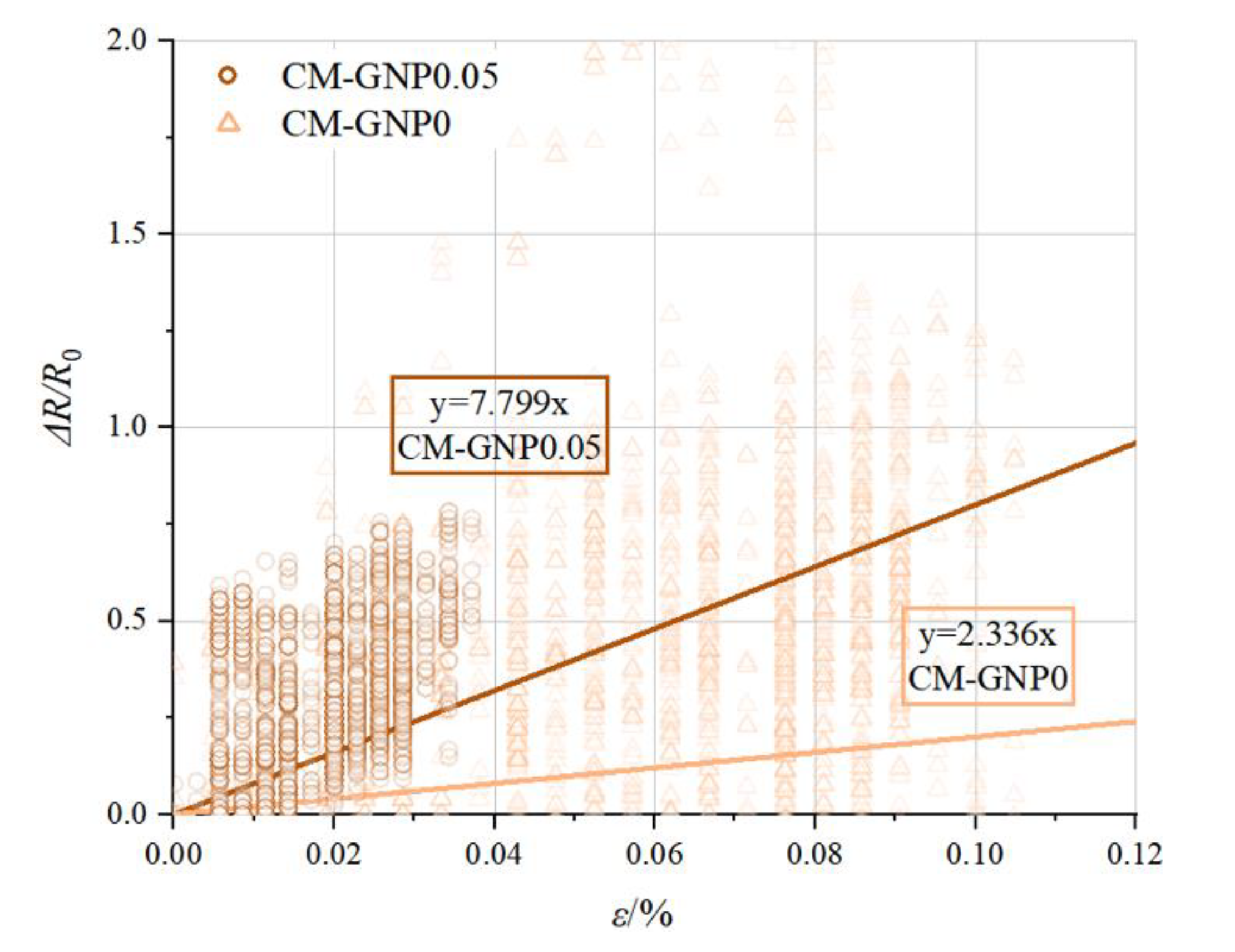
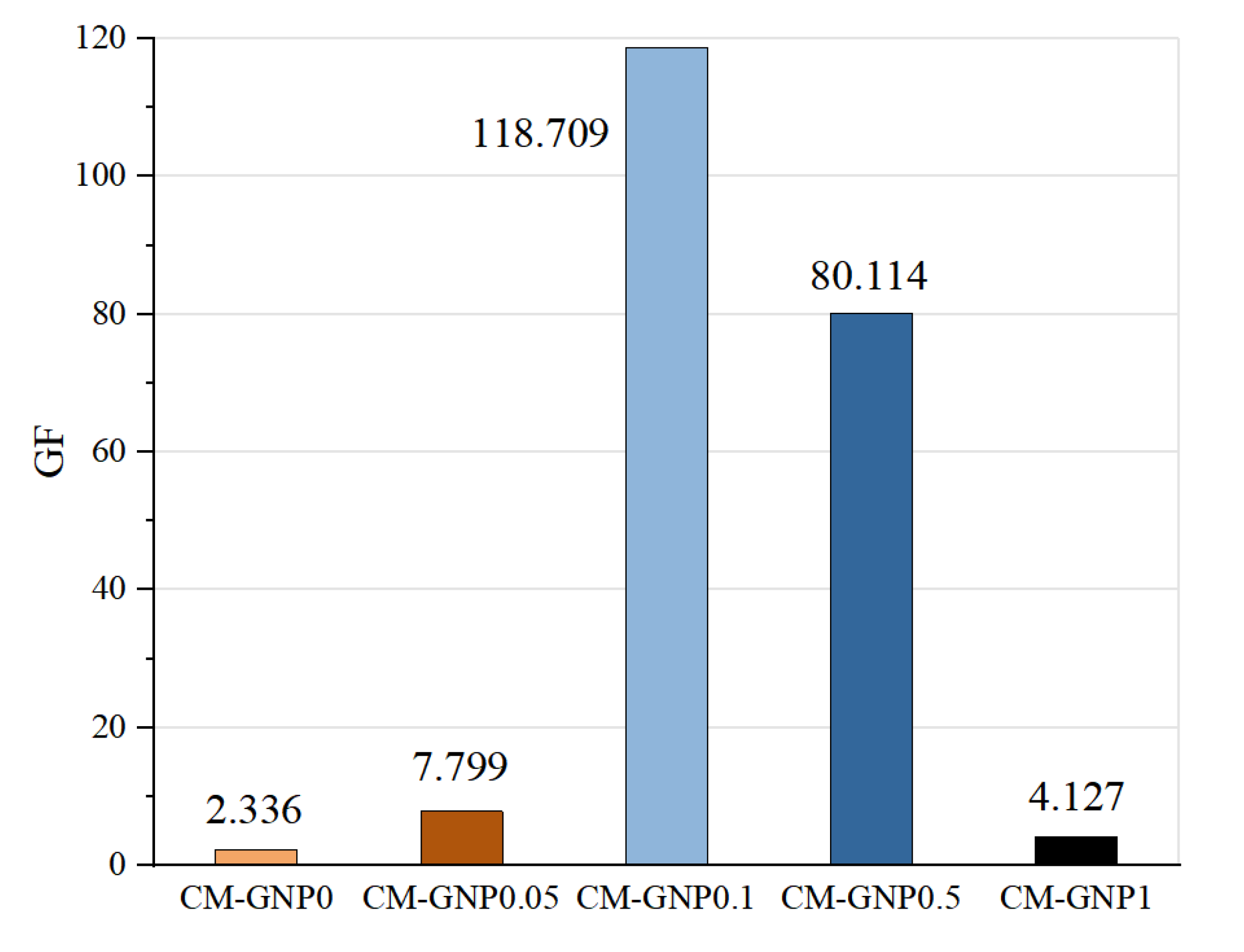
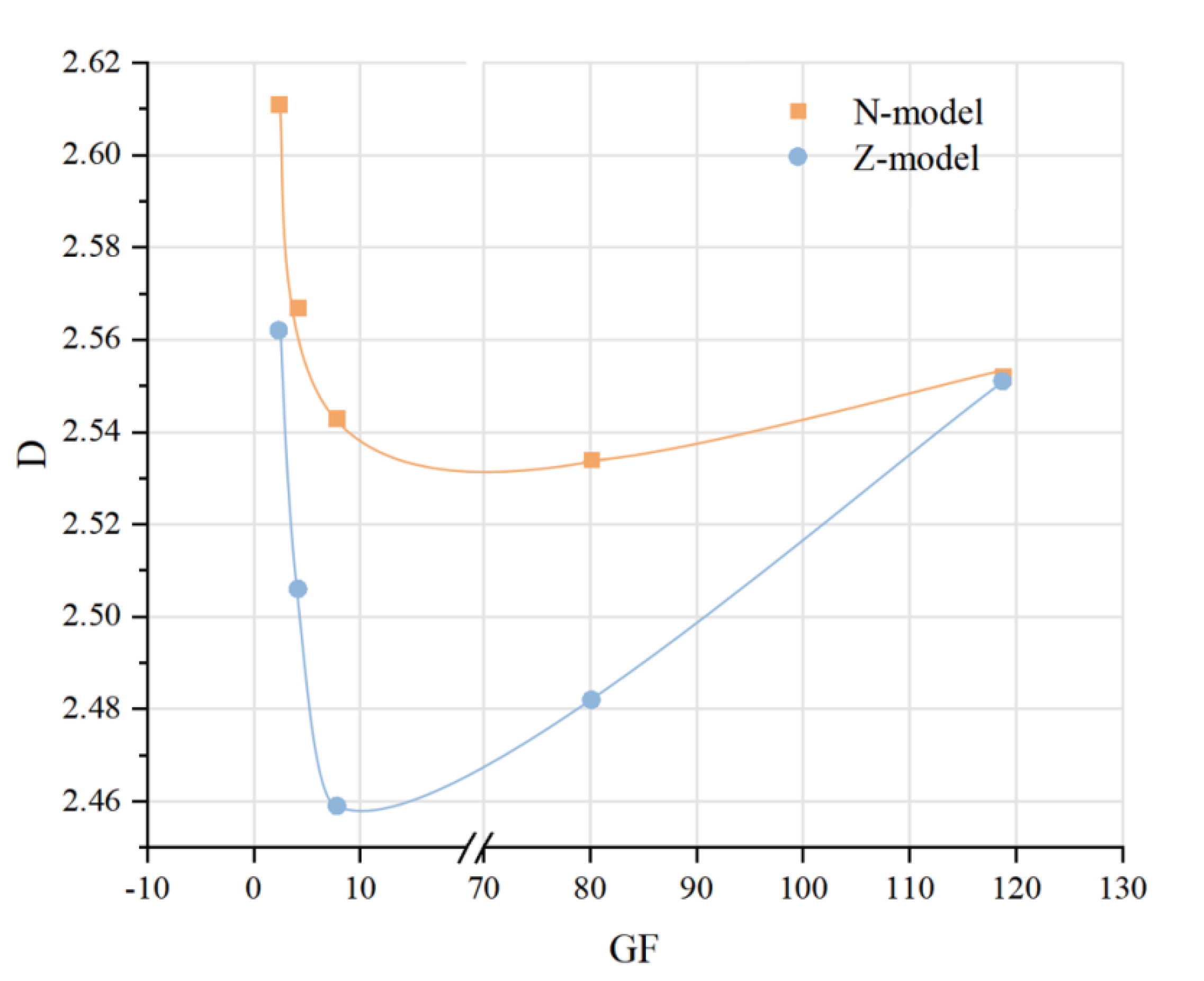
3.4. Relationship Between Gauge Factor and Fractal Dimensions

The relationship between GF and fractal dimensions in the micro region (region Ⅲ) is plotted in Figure 11. Under both methods, fractal dimensions decrease first and then increase with the increase of GF values. The lowest fractal dimensions appear in the samples with the highest GNP content. The complex GF-fractal dimension relationships induce difficulties in practical applications of fractal theories for electrical properties prediction.
The mechanisms of piezoresistivity of CBMs with conductible fillers (e.g., GNPs in this work) relay on the complex interactions between the fillers and cement matrix (Figure 12).At low or zero filling extents, such as CM-GNP0 and CM-GNP0.05, GNPs are relatively dilute in the cement matrix, and the distances between the neighbored GNPs can hardly trigger the tunnel effect, so the piezoresistive behaviors of the materials are not obvious (Figure 5 and Figure 8). As more GNPs are included in the cement matrix, the distances of the GNPs become closer, and the tunnel effect may be triggered. In this tunnel effect, when potential energy is applied to both ends to form a potential barrier V, some particles with kinetic energy E in the conductor can pass through the potential barrier V from one side to the other side under the condition that E < V (left panel in Figure 12) [60]. This regime would greatly increase the piezoresistivity of cement mortars with proper conductible fillers, such as CM-GNP0.1 and CM-GNP0.5.
However, the semi-conductive status dominated by the tunnel effect can easily be changed as the content of conductible fillers is further increased. In our case, the heavily included GNPs (CM-GNP0.1) are feasible to form not only the agglomerations that increase the surface roughness of the fracture surfaces (Figure 3e,f), but also the percolation paths that change the material to be conductible (right panel in Figure 12). In this case, contact conduction becomes dominant [52,71]. It is noteworthy that the above tunneling and contact conduction mechanisms can change the piezoresistive properties significantly, but may have little impacts on the packing patterns of C-S-H in micro scales. So the fractal dimensions, that reflect the compaction of nano particles [66], are changed in minor extents for the cement mortars with GNPs (Table 3; Table 4). Practically, from the findings of this work, it shows complex relationship between the piezoresistive behaviors of cement composites and fractal dimensions.

4. Conclusions

The incorporation of GNPs into cement mortar impacts the microstructure and piezoresistive performance of cement mortar in different regimes. Proper GNP contents can improve the FCR and GF values. The cement mortar with 0.1% GNPs shows the optimum GF values at 118.7, almost two orders of magnitude higher than the neat cement mortar. Fractal analyses by the N-model and the Z-model show that the pore structure of the GNP-modified cement mortars have macro- and micro-fractal regions. Fractal dimensions show no appealing correlations with GNP content, but have non-linear relationships with GF values. The tunneling effect and percolation effect dominates the piezoresistivity of the cement mortars with low and high GNP contents respectively.

Author Contributions

Conceptualization, Q.Z. and W.Z.; methodology, J.T. and N.D.; software, N.D.; validation, N.D.; formal analysis, N.D.; investigation, N.D.; resources, Q.Z.; data curation, J.T. and N.D.; writing—original draft preparation, N.D.; writing—review and editing, Q.Z.; visualization, N.D. and Q.Z.; supervision, Q.Z. and W.Z.; project administration, Q.Z. and W.Z.; funding acquisition, Q.Z. All authors have read and agreed to the published version of the manuscript.

Funding

This research was funded by the National Natural Science Foundation of China (grant number 51878602) and the Center for Balance Architecture, Zhejiang University.

Data Availability Statement

Not applicable.

Acknowledgments

We acknowledge Yu Peng for experimental support.

Conflicts of Interest

The authors declare no conflict of interest.

References

  1. Dong, W.K.; Guo, Y.P.; Sun, Z.H.; Tao, Z.; Li, W.G. Development of piezoresistive cement-based sensor using recycled waste glass cullets coated with carbon nanotubes. J. Clean. Prod. 2021, 314, 127968. [Google Scholar] [CrossRef]
  2. Xu, J.X.; Yin, T.J.; Wang, Y.; Liu, L. Anisotropic electrical and piezoresistive sensing properties of cement-based sensors with aligned carbon fibers. Cem. Concr. Compos. 2020, 116, 103873. [Google Scholar] [CrossRef]
  3. D’Antonella, A.; Matteo, T.; Andrea, M.; Filippo, U. Improved strain sensing properties of cement-based sensors through enhanced carbon nanotube dispersion. Cem. Concr. Compos. 2021, 115, 103842. [Google Scholar]
  4. Rouhi, S.; Moradi, H.; Hakimi, Y.; Nikpour, F. On the mechanical properties of the graphyne and graphdiyne with patterned hydrogenation and hole: A molecular dynamics investigation. Appl. Phys. A 2020, 126, 1–28. [Google Scholar] [CrossRef]
  5. Wu, Y.; Ma, C.; Chen, Y.; Mortazavi, B.; Lu, Z.; Zhang, X.; Xu, K.; Zhang, H.; Liu, W.; Rabczuk, T.; et al. New group V graphyne: Two-dimensional direct semiconductors with remarkable carrier mobilities, thermoelectric performance, and thermal stability. Mater. Today Phys. 2020, 12, 100164. [Google Scholar] [CrossRef]
  6. Fazel, S.; Bohayra, M. Ultrahigh carrier mobility, Dirac cone and high stretchability in pyrenyl and pyrazinoquinoxaline graphdiyne/graphyne nanosheets confirmed by first-principles. Appl. Surf. Sci. 2021, 557, 149699. [Google Scholar]
  7. Li, X.Y.; Liu, Y.M.; Li, W.G.; Li, C.Y.; Sanjayan, J.G.; Duan, W.H.; Li, Z.J. Effects of graphene oxide agglomerates on workability, hydration, microstructure and compressive strength of cement paste. Constr. Build. Mater. 2017, 145, 402–410. [Google Scholar] [CrossRef]
  8. Wu, Y.Y.; Que, L.X.; Cui, Z.Y.; Lambert, P. Physical Properties of Concrete Containing Graphene Oxide Nanosheets. Materials 2019, 10, 1707. [Google Scholar] [CrossRef] [Green Version]
  9. Peng, H.; Ge, Y.P.; Cai, C.S.; Zhang, Y.X.; Liu, Z. Mechanical properties and microstructure of graphene oxide cement-based composites. Constr. Build. Mater. 2019, 194, 102–109. [Google Scholar] [CrossRef]
  10. Li, P.Q.; Liu, J.X.; Her, S.W.; Erfan, Z.N.; Seungmin, L.; Sungchul, B. Synthesis of Highly-Dispersed Graphene Oxide Nanoribbons-Functionalized Carbon Nanotubes-Graphene Oxide (GNFG) Complex and Its Application in Enhancing the Mechanical Properties of Cementitious Composites. Nanomaterials 2021, 11, 1669. [Google Scholar] [CrossRef]
  11. Wang, J.Y.; Tao, J.; Li, L.; Zhou, C.S.; Zeng, Q. Thinner fillers, coarser pores? A comparative study of the pore structure alterations of cement composites by graphene oxides and graphene nanoplatelets. Compos. Part A 2020, 130, 105750. [Google Scholar] [CrossRef]
  12. Zhu, X.H.; Kang, X.J.; Deng, J.X.; Yang, K.; Yu, L.W.; Yang, C.H. A comparative study on shrinkage characteristics of graphene oxide (GO) and graphene nanoplatelets (GNPs) modified alkali-activated slag cement composites. Mater. Struct. 2021, 54, 106. [Google Scholar] [CrossRef]
  13. Zhu, X.H.; Kang, X.J. Effect of graphene oxide(GO) on the hydration and dissolution of alite in a synthetic cement system. J. Mater. Sci. 2020, 55, 3419–3433. [Google Scholar] [CrossRef]
  14. Goracci, G.; Dolado, J.S. Elucidation of Conduction Mechanism in Graphene Nanoplatelets (GNPs)/Cement Composite Using Dielectric Spectroscopy. Materials 2020, 13, 275. [Google Scholar] [CrossRef] [Green Version]
  15. Ioanna, P.; Livia, R.S.; Chrysoula, L.; Abir, A.T. Investigation of the dispersion of multi-layer graphene nanoplatelets in cement composites using different superplasticiser treatments. Constr. Build. Mater. 2021, 293, 123543. [Google Scholar]
  16. Zhang, Q.; Sun, H.; Liu, W.G.; Zhou, Z.H.; Yuan, L.W.; Ren, Z.C.; Geng, D.J.; Wang, J.B.; Cheng, X. Effect of rGO on the mechanical strength, hydration and micromorphology of cement incorporated silica fume. Constr. Build. Mater. 2021, 300, 124325. [Google Scholar] [CrossRef]
  17. Rodríguez-Tembleque, L.; García-Sánchez, F.; García-Macías, E.; Buroni, F.C.; Sáez, A. Crack-induced electrical resistivity changes in cracked CNT-reinforced composites. Theor. Appl. Fract. Mech. 2020, 106, 102470. [Google Scholar] [CrossRef]
  18. Xu, J.M.; Zhang, D. Pressure-sensitive properties of emulsion modified graphene nanoplatelets/cement composites. Cem. Concr. Compos. 2017, 84, 74–82. [Google Scholar] [CrossRef]
  19. Wang, M.; Wang, R.; Yao, H. Study on the three dimensional mechanism modified cement. Construction and Building. Constr. Build. Mater. 2016, 126, 730–739. [Google Scholar]
  20. Li, C.Y.; Chen, S.J.; Li, W.G.; Li, X.Y.; Ruan, D.; Duan, W.H. Dynamic increased reinforcing effect of graphene oxide on cementitious nanocomposite. Constr. Build. Mater. 2019, 206, 694–702. [Google Scholar] [CrossRef]
  21. Gholampour, A.; Valizadeh, K.M.; Tran, D.N.H.; Ozbakkaloglu, T.; Losic, D. From graphene oxide: Impact on the physiochemical and mechanical properties of graphene-cement composites. ACS Appl. Mater. Interfaces 2017, 9, 43275–43286. [Google Scholar] [CrossRef]
  22. Buasiri, T.; Habermehl-Cwirzen, K.; Krzeminski, L.; Cwirzen, A. Piezoresistive Load Sensing and Percolation Phenomena in Portland Cement Composite Modified with In-Situ Synthesized Carbon Nanofibers. Nanomaterials 2019, 9, 594. [Google Scholar] [CrossRef] [Green Version]
  23. Jin, T.; Wang, X.H.; Wang, Z.D.; Zeng, Q. Graphene nanoplatelets as an effective additive to tune the microstructures and piezoresistive properties of cement-based composites. Constr. Build. Mater. 2019, 209, 665–678. [Google Scholar]
  24. Liu, C.J.; Huang, X.C.; Wu, Y.Y.; Deng, X.W.; Zheng, Z.L.; Xu, Z.; Hui, D. Advance on the dispersion treatment of graphene oxide and the graphene oxide modified cement-based materials. Nanotechnol. Rev. 2021, 10, 34–49. [Google Scholar] [CrossRef]
  25. Zeng, Q.; Li, K.F.; Fen-Chong, T. Surface fractal analysis of pore structure of high-volume fly-ash cement pastes. Appl. Surf. Sci. 2010, 257, 762–768. [Google Scholar] [CrossRef]
  26. Li, Y.; Zhang, H.; Huang, M.; Yin, H.; Jiang, K.; Xiao, K.; Tang, S. Influence of Different Alkali Sulfates on the Shrinkage, Hydration, Pore Structure, Fractal Dimension and Microstructure of Low-Heat Portland Cement, Medium-Heat Portland Cement and Ordinary Portland Cement. Fractal Fract. 2021, 5, 79. [Google Scholar] [CrossRef]
  27. Tang, S.; Wang, Y.; Geng, Z.C.; Xu, X.F.; Yu, W.Z.; A, H.; Chen, J.T. Structure, fractality, mechanics and durability of calcium silicate hydrates. Fractal Fract. 2021, 5, 47. [Google Scholar] [CrossRef]
  28. Wang, L.; Guo, F.X.; Lin, Y.Q.; Yang, H.M.; Tang, S.W. Comparison between the effects of phosphorous slag and fly ash on the C-S-H structure, long-term hydration heat and volume deformation of cement-based materials. Constr. Build. Mater. 2020, 250, 118807. [Google Scholar] [CrossRef]
  29. Wang, P.G.; Mo, R.; Li, S.; Xu, J.; Jin, Z.Q.; Zhao, T.J.; Wang, D.Z. A chemo-damage-transport model for chloride ions diffusion in cement-based materials: Combined effects of sulfate attack and temperature. Constr. Build. Mater. 2021, 288, 123121. [Google Scholar] [CrossRef]
  30. Wang, L.; Jin, M.; Zhou, S.; Tang, S.W.; Lu, X. Investigation of microstructure of C-S-H and micro-mechanics of cement pastes under NH4NO3 dissolution by 29Si MAS NMR and microhardness. Measurement 2021, 185, 110019. [Google Scholar] [CrossRef]
  31. Yaghoobi, K.R. A new approach to measure the fractal dimension of a trajectory in the high-dimensional phase space. Chaos Solitons Fractals 2021, 151, 111239. [Google Scholar]
  32. Tiina, V.; Gregor, R.; Anastasiia, L.; Basel, R.; Herje, S.; Liisa, P.; Mari, K.; Frank, L. Analysis of membrane fouling by Brunauer-Emmet-Teller nitrogen adsorption/desorption technique. Sci. Rep. 2020, 10, 3427. [Google Scholar]
  33. Chinh, N.D.; Hien, T.T.; Do, V.L.; Hieu, N.M.; Quang, N.D.; Lee, S.-M.; Kim, C.; Kim, D. Adsorption/desorption kinetics of nitric oxide on zinc oxide nano film sensor enhanced by light irradiation and gold-nanoparticles decoration. Sens. Actuators B Chem. 2019, 281, 262–272. [Google Scholar] [CrossRef]
  34. Muratov, D.S.; Gromov., S. Evaluating Hydrogen Uptake for Two Types of Multi-Wall Carbon Nanotubes from Nitrogen Adsorption/Desorption Data. Nano Hybrids Compos. 2017, 13, 341–347. [Google Scholar] [CrossRef]
  35. Yury, V.Z.; Natalia, A.; Philip, V.H.; Nele, D.B. Pore Size Distribution and Surface Multifractal Dimension by Multicycle Mercury Intrusion Porosimetry of GGBFS and Limestone Powder Blended Concrete. Appl. Sci. 2021, 11, 4851. [Google Scholar]
  36. Yang, Q.; Xue, J.; Li, W.; Du, X.; Ma, Q.; Zhan, K.; Chen, Z. Comprehensive evaluation and interpretation of mercury intrusion porosimetry data of coals based on fractal theory, Tait equation and matrix compressibility. Fuel 2021, 298, 120823. [Google Scholar] [CrossRef]
  37. Gao, Y.; Wu, K.; Yuan, Q. Limited fractal behavior in cement paste upon mercury intrusion porosimetry test: Analysis and models. Constr. Build. Mater. 2021, 276, 122231. [Google Scholar] [CrossRef]
  38. Wang, X.L.; Pan, J.N.; Wang, K.; Ge, T.Y.; Wei, J.; Wu, W. Characterizing the shape, size, and distribution heterogeneity of pore-fractures in high rank coal based on X-ray CT image analysis and mercury intrusion porosimetry. Fuel 2020, 282, 118754. [Google Scholar] [CrossRef]
  39. Domenico, L.; Pietro, C.; Kiselev, M.A. Structural Characterization of Biomaterials by Means of Small Angle X-rays and Neutron Scattering (SAXS and SANS), and Light Scattering Experiments. Molecules 2020, 25, 5624. [Google Scholar]
  40. Yokaichiya, F.; Schmidt, C.; Storsberg, J.; Vollrath, M.K.; Araujo, D.R.; Kent, B.; Clemens, D.; Wingert, F.; Franco, M.K. Effects of doxorubicin on the structural and morphological characterization of solid lipid nanoparticles (SLN) using small angle neutron scattering (SANS) and small angle X-ray scattering (SAXS). Phys. B Phys. Condens. Matter 2018, 551, 191–196. [Google Scholar] [CrossRef]
  41. Razyq, N.; Luo, G.H.; Neil, R.; Fourie, A.; Johns, M.L.; Fridjonsson Einar, O. Understanding the microstructural evolution of hypersaline cemented paste backfill with low-field NMR relaxation. Cem. Concr. Res. 2021, 147, 106516. [Google Scholar]
  42. Wang, Y.; Diamand, S. A fractal study of the fracture surfaces of cement pastes and mortars using a stereoscopic SEM method. Cem. Concr. Res. 2001, 31, 1385–1392. [Google Scholar] [CrossRef]
  43. Niu, D.; Huang, D.; Zheng, H.; Su, L.; Fu, Q.; Luo, D. Experimental study on mechanical properties and fractal dimension of pore structure of basalt-polypropylene fiber-reinforced concrete. Appl. Sci. 2019, 9, 1602. [Google Scholar] [CrossRef] [Green Version]
  44. Zhang, L.C.; Zhou, J.K. Fractal characteristics of pore structure of hardened cement paste prepared by pressurized compact molding. Constr. Build. Mater. 2020, 259, 119856. [Google Scholar] [CrossRef]
  45. Calati, M.; Monte, E.D.; Mancin, S. Numerical Analysis of the Effects of the Structure Shape and Orientation of Kelvin Cell Porous Structures during Air Forced Convection. Appl. Sci. 2021, 11, 6189. [Google Scholar] [CrossRef]
  46. Kashchenko, S. Local Dynamics of Logistic Equation with Delay and Diffusion. Mathematics 2021, 9, 1566. [Google Scholar] [CrossRef]
  47. Pia, G.; Sanna, U. A geometrical fractal model for the porosity and thermal conductivity of insulting concrete. Constr. Build. Mater. 2013, 44, 551–556. [Google Scholar] [CrossRef]
  48. Tang, S.W.; He, Z.; Cai, X.H.; Cai, R.J.; Zhou, W.; Li, Z.J.; Shao, H.Y.; Wu, T.; Chen, E. Volume and surface fractal dimensions of pore structure by NAD and LT-DSC in calcium sulfoaluminate cement pastes. Constr. Build. Mater. 2017, 143, 395–418. [Google Scholar] [CrossRef]
  49. Dong, W.K.; Li, W.G.; Vessalas, K.; He, X.Z.; Sun, Z.H.; Sheng, D.C. Piezoresistivity deterioration of smart graphene nanoplate/cement-based sensors subjected to sulphuric acid attack. Compos. Commun. 2021, 23, 100563. [Google Scholar] [CrossRef]
  50. Szeląg, M. Mechano-Physical Properties and Microstructure of Carbon Nanotube Reinforced Cement Paste after Thermal Load. Nanomaterials 2017, 7, 269. [Google Scholar] [CrossRef] [Green Version]
  51. Wu, Z.Q.; Wei, J.; Dong, R.Z. Graphene-based piezoresistive composite and applicationin crack monitoring. J. ZheJiang Univ. 2020, 54, 233–240. [Google Scholar]
  52. Frac, M.; Waldemar, P. Piezoresistive properties of cement composites with expanded graphite. Compos. Commun. 2020, 19, 99–102. [Google Scholar] [CrossRef]
  53. Neimark, A.V. A new approach to the determination of the surface fractal dimension of porous solids. Phys. A 1992, 191, 258–262. [Google Scholar] [CrossRef]
  54. Rootare, H.M.; Prenzlow, C.F. Surface areas from mercury porosimeter measurements. J. Phys. Chem. 1967, 71, 2733–2736. [Google Scholar] [CrossRef]
  55. Pfeifer, P.; Avnir, D. Chemistry in noninteger dimensions between two and three I. Fractal theory of heterogeneous surface. J. Chem. Phys. 1983, 79, 3558–3565. [Google Scholar] [CrossRef]
  56. Zhang, B.; Li, S. Determination of the surface fractal dimension for porous media by mercury porosimetry. Ind. Eng. Chem. Res. 1995, 34, 1383–1386. [Google Scholar] [CrossRef]
  57. Zhang, B.; Liu, W.; Liu, X. Scale-dependent nature of the surface fractal dimension for bi- and multi-disperse porous solids by mercury porosimetry. Appl. Surf. Sci. 2006, 253, 1349–1355. [Google Scholar] [CrossRef]
  58. Matalkah, F.; Soroushian, P. Graphene nanoplatelet for enhancement the mechanical properties and durability characteristics of alkali activated binder. Constr. Build. Mater. 2020, 249, 118773. [Google Scholar] [CrossRef]
  59. Du, H.; Gao, H.J.; Pang, S.D. Improvement in concrete resistance against water and chloride ingress by adding graphene nanoplatelet. Cem. Concr. Res. 2016, 83, 114–123. [Google Scholar] [CrossRef]
  60. Papanikolaou, I.; Arena, N.; Al-Tabbaa, A. Graphene nanoplatelet reinforced concrete for self-sensing structures—A lifecycle assessment perspective. J. Clean. Prod. 2019, 240, 118202. [Google Scholar] [CrossRef]
  61. Al-Dahawi, A.; Sarwary, M.H.; Öztürk, O.; Yıldırım, G.; Akın, A.; Sahmaran, M.; Lachemi, M. Electrical percolation threshold of cementitious composites possessing self-sensing functionality incorporating different carbon-based materials. Smart Mater. Struct. 2016, 25, 105005. [Google Scholar] [CrossRef]
  62. Jia, X.W.; Zhang, X.; Ma, D.; Yang, Z.F.; Shi, C.L.; Wang, Z. Conductive properties and influencing factors of electrically conductive concrete: A review. Mater. Rep. 2017, 31, 90–97. [Google Scholar]
  63. Belli, A.; Mobili, A.; Bellezze, T.; Tittarelli, F.; Cachim, P. Evaluating the Self-Sensing Ability of Cement Mortars Manufactured with Graphene Nanoplatelets, Virgin or Recycled Carbon Fibers through Piezoresistivity Tests. Sustainability 2018, 10, 4013. [Google Scholar] [CrossRef] [Green Version]
  64. Li, D.B.; Lei, P.B.; Zhang, H.C.; Liu, J.P.; Lu, W.; Majewski, P. Co-Effects of Graphene Oxide and Cement on Geotechnical Properties of Loess. Adv. Mater. Sci. Eng. 2021, 2021, 7429310. [Google Scholar]
  65. García-Macías, E.; Alessandro, A.D.; Castro-Triguero, R.; Pérez-Mira, D.; Bertini, F.U. Micromechanics modeling of the uniaxial strain-sensing propertyof carbon nanotube cement-matrix composites for SHM applications. Constr. Build. Mater. 2017, 163, 195–215. [Google Scholar]
  66. Li, H.; Xiao, H.; Ou, J. Effect of compressive strain on electrical resistivity ofcarbon black-filled cement-based composites. Constr. Build. Mater. 2006, 28, 824–828. [Google Scholar]
  67. Guo, R.X.; Suo, Y.X.; Xia, H.T.; Yang, Y.; Ma, Q.M.; Yan, F. Study of Piezoresistive Behavior of Smart Cement Filled with Graphene Oxide. Nanomaterials 2021, 11, 206. [Google Scholar] [CrossRef]
  68. Zeng, Q.; Luo, M.; Pang, X.; Li, K. Surface fractal dimension: An indicator to characterize the microstructure of blended cement-based materials. Appl. Surf. Sci. 2013, 282, 302–307. [Google Scholar] [CrossRef]
  69. Fan, J.C.; Zhang, B. Repair of ordinary Portland cement concrete using alkali activated slag/fly ash: Freeze-thaw resistance and pore size evolution of adhesive interface. Constr. Build. Mater. 2021, 300, 124334. [Google Scholar] [CrossRef]
  70. Lv, Q.; Qiu, Q.; Zheng, J.; Wang, J.; Zeng, Q. Fractal dimension of concrete incorporating silica fume and its correlations to pore structure, strength and permeability. Constr. Build. Mater. 2019, 228, 116986. [Google Scholar]
  71. Han, J.X.; Cai, J.M.; Pan, J.L.; Sun, Y.Q. Study on the conductivity of carbon fiber self-sensing high ductility cementitious composite. J. Build. Eng. 2021, 43, 103125. [Google Scholar] [CrossRef]
Figure 1. Chart flow of GNP-modified cement mortar preparation (left) and an example of examining the dispersion efficiency of GNP suspension and SEM characteristic of GNP particles (right).
Fractalfract 05 00148 g001
Figure 2. Arrangement of four-probe piezoresistive test.
Fractalfract 05 00148 g002
Figure 3. Typical SEM characteristics of GNPs-modified cement mortars: (a) CM-GNP0, (b) CM-GNP0.05, (c) CM-GNP0.1, (d) CM-GNP0.5, (e) CM-GNP1, and (f) agglomerations in a local area of CM-GNP1.
Fractalfract 05 00148 g003
Figure 4. Stress and FCR curves of the GNP-modified cement mortars during the cyclic compression loads.
Fractalfract 05 00148 g004
Figure 5. FCR-strain plots for CM-GNP0 (slope = 2.336, R2 = 0.009) and CM-GNP0.05 (slope = 7.799, R2 = 0.202).
Fractalfract 05 00148 g005
Figure 6. FCR-strain plots for CM-GNP0.1 (slope = 118.709, R2 = 0.867) and CM-GNP0.5 (slope = 80.709, R2 = 0.835).
Fractalfract 05 00148 g006
Figure 7. FCR-strain plots for CM-GNP1 (slope = 4.127, R2 = 0.290).
Fractalfract 05 00148 g007
Figure 8. GF values of the GNP-modified cement mortars.
Fractalfract 05 00148 g008
Figure 9. Fractal plots of the GNP-modified cement mortars by the N-model (top) and the Z-model (bottom).
Fractalfract 05 00148 g009
Figure 10. Pore ranges of fractal regions from the N-model (left) and Z-model (right).
Fractalfract 05 00148 g010
Figure 11. The relationships between gauge factor (GF) and fractal dimensions (D).
Fractalfract 05 00148 g011
Figure 12. The mechanisms of tunnel effect conduction (left) and percolation conduction (right).
Fractalfract 05 00148 g012
Table 1. Chemical and mineral composition of cement.
Chemical CompositionPercentageMineralPercentage
SiO222.15C3S56.54
Al2O34.51C2S20.87
Fe2O33.39C3A6.22
CaO65.36C4AF10.31
MgO2.31
SO30.46
NaOeq0.488
f-CaO0.95
Table 2. Mix proportions of the GNP-modified cement mortars.
Sample IDGNP(%)Cement (g)Water (g)Sand (g)Dispersant (g)
CM-GNP0090033027004.5
CM-GNP0.050.05
CM-GNP0.10.1
CM-GNP0.50.5
CM-GNP11.0
Table 3. Surface fractal analysis by the N-model.
Specimen CM-GNP0CM-GNP0.05CM-GNP0.1CM-GNP0.5CM-GNP1
GNP 00.05%0.1%0.5%1%
Region ⅠDN2.8772.7842.8142.8432.776
Pore diameter>4322 nm>4050 nm>4526 nm>4452 nm>4520 nm
Region ⅡDN-----
Pore diameter32–4322 nm40–4050 nm40–4526 nm32–4452 nm32–4520 nm
Region ⅢDN2.6112.5432.5522.5342.567
Pore diameter<32 nm<40 nm<40 nm<32 nm<32 nm
Table 4. Surface fractal analysis by the Z-model.
Specimen CM-GNP0CM-GNP0.05CM-GNP0.1CM-GNP0.5CM-GNP1
GNP 00.05%0.1%0.5%1%
RegionⅠDZ2.4722.4472.4462.4652.422
Pore diameter>2416 nm>3011 nm>3044 nm>2681 nm>3069 nm
Region ⅡDZ-----
Pore diameter50–2416 nm40–3011 nm50–3044 nm40–2681 nm50–3069 nm
Region ⅢDZ2.5622.4592.5512.4822.506
Pore diameter<50 nm<40 nm<50 nm<40 nm<50 nm
Publisher’s Note: MDPI stays neutral with regard to jurisdictional claims in published maps and institutional affiliations.

