1. Introduction
An advanced combustion monitoring concept featuring a combined optic-acoustic measurement system for the monitoring of combustion in power gas turbines and aircraft engines is presented in this paper.
Aero engines are vital propulsion systems for modern civil and military aircraft. The overall gas turbine cycle works according to simple principles, mainly dependent on fresh fuel and air supply. Nonetheless, it is getting increasingly important to better understand combustion in gas turbines to finer tune the operations and to react to changes in combustion behaviour in a timely manner. A better combustion monitoring would lead to smarter management of the operational safety margin, which in turns would result in significant fuel savings and pollutant reduction.
Therefore since 2015, Combustion Bay One e.U. and FH JOANNEUM GmbH jointly worked on combustion precision monitoring in a project called “emootion”. It was shown in a previous publication [
1] that it makes sense to correlate sound signals and chemiluminescence intensities from the flame to obtain detailed combustion monitoring. A special design called Rayleigh Criterion Probe (RCP) was produced for combustion under standard conditions. It was shown how important the luminescence signal can be, e.g., to avoid possible misinterpretations of the fast pressure signal. The feasibility study on optical-based instrumentation for better combustion monitoring achieved TRL 2 by 2017. All the following features could be monitored in separate experiments by the same instrumentation: the presence of a flame, an indication about the success (or good repetition) of the ignition sequence, an indication about the flame regime, and an indication about combustion stability (or to the opposite, the detection of combustion instability).
This paper is an extension of previous works towards a higher TRL (e.g., TRL 4, laboratory validation at realistic conditions of operation). One vision of the emootion technology is to equip a gas turbine combustor with a discrete number of RCPs (minimum of three specimens) combining optical and acoustic measurements for an advanced monitoring of the combustion. This technology should be portable and should describe in a satisfying and detailed manner the ignition process, the current operation point (to which is added the production of soot), and the identification of combustion instability modes if present.
The latest research focuses therefore on two aspects regarding the deployment of the RCP concept: redundancy and discrete spectral band analysis. In the first place, the readings of spatially installed RCPs within the combustion chamber cavity are investigated. Two probes are placed with an axial shift, while the third one is placed with a tangential shift with respect to the combustion chamber design. This allows statements about the presence of a flame, the ignition sequence, and the flame spatial propagation. Furthermore, with this concept, a basic modal analysis for combustion instability can be conducted. For the second aspect, the probes are equipped with different wave length optical band-pass filters, thus enabling an assertion of the combustion process such as soot generation and further relevant emission spectra at the current operating point of the engine. As a consequence of this feature, each probe allocates a separate role concerning combustion assessment. A combination of both measurement system features enables quantitative and qualitative real-time combustion monitoring.
The paper starts with the incentives and challenges of optical measurement techniques in gas turbines. The technical choices regarding the sensor, the spectral bands, and the probe assembly are detailed with focus on the Red-Green-Blue (RGB) method. An intermediate combustion pressure rig is presented, using the burner detailed in paper [
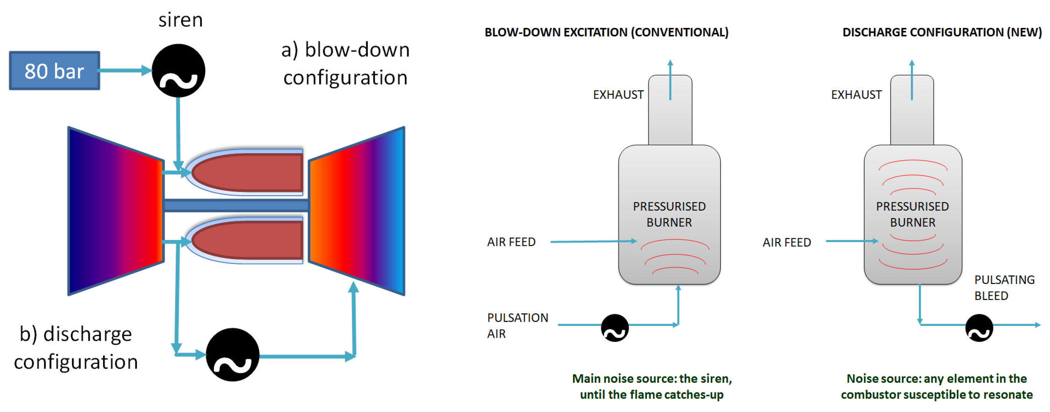
2]. The setup is designed to produce in well-controlled and repeatable manner ignition sequences, steady operation, and combustion instability. The excitation method of the flame to drive combustion instabilities is presented separately, with a siren mounted in blow-down as well as in discharge mode [
3]. The discharge mode separates the sound source and therefore reduces the noise contribution from the siren as well as avoids unrealistic flow rate fluctuations at the level of the burner. This method was positively assessed and is suggested in the discussion as a possible combustor stability benchmarking method. The prototype component testing is validated, and a fully integrated demonstration is performed under intermediate pressure and temperature conditions. It is shown that atmospheric and pressure tests achieve good agreement while using the RCPs. The benchmarking strategies are presented, among others, regarding ignition monitoring and stability monitoring, with novel strategies to identify combustion instabilities in the kHz domain.
The conclusion summarises the progress made in terms of RCP technology and in terms of experimental methods. Then, it discusses the path towards industrialisation. To this aim, the technical challenges are named, and promising solutions are suggested. A compact and portable combustion monitoring system including at least 3 RCPs can become an instrumentation standard for detailed combustion monitoring and machine protection within the next decade.
2. Make Use of the Flame’s Light for Better Combustion Monitoring
Light is a general term for luminescence, which is one characteristic aspect of reactive thermochemistry in the combustion processes. While many of the combustion diagnostic techniques in the laboratory are optical-based [
4], only a few optical instruments such as flame scanners [
5] are currently used in thermal facilities. The incentive of this work is to exploit the light emitted by the flame in the pressurised combustor of a gas turbine.
2.1. Support the Standard Instrumentation
The proposal is to supplement the gas turbine on-board standard instrumentation (such as mass flow meters, temperature sensor, fast pressure probes, and accelerometers) with robust and reliable information about the combustor flame status. Under well-known operations (e.g., during cruise), the additional information refines the combustion diagnostic in real time so that small corrections can be done on the inlet conditions of the combustor to greatly improve the combustion quality. Under transient conditions or near the safety limits (e.g., lowest admissible lean operation), the instrumentation can confirm that an alarm is indeed related to the flame (e.g., the typical flickering of the flame near lean blow-off is confirmed, and the machine must promptly move to a more conservative and stable operation point).
The requirements of an optical technique are direct or indirect optical access to the flame. This measurement could be through the burner, facing a cooling hole, or gathering reflections. The sensing must have a high sensibility, with a signal-to-noise ratio high enough, on the one hand, to differentiate the presence of a flame versus no flame and, on the other hand, to cover the maximum span of intensity from lean premixed (flame in blue modus, lowly radiative, where the light intensity is representative of the thermal power [
6]) to the diffusion flame (strongly radiative, disconnected from the thermal power). Despite the exponential behaviour of light intensity between the two types of flames mentioned above, it shall not meet saturation. The sensing must be fast. It must catch flame turbulence information in the 0–5 kHz domain, so that the main flow features such as the precise ignition description are included or so that combustion instabilities can be studied at least up to the second harmonic. The sensing must offer a selective chromatic spectral bandwidth (e.g., differentiate the flame’s radiation from glowing walls). Last but not least, since it is designed to be eventually airborne, technical considerations must focus on candidates for a precise, lightweight, compact, and highly reliable monitoring system.
2.2. Technical Challenge
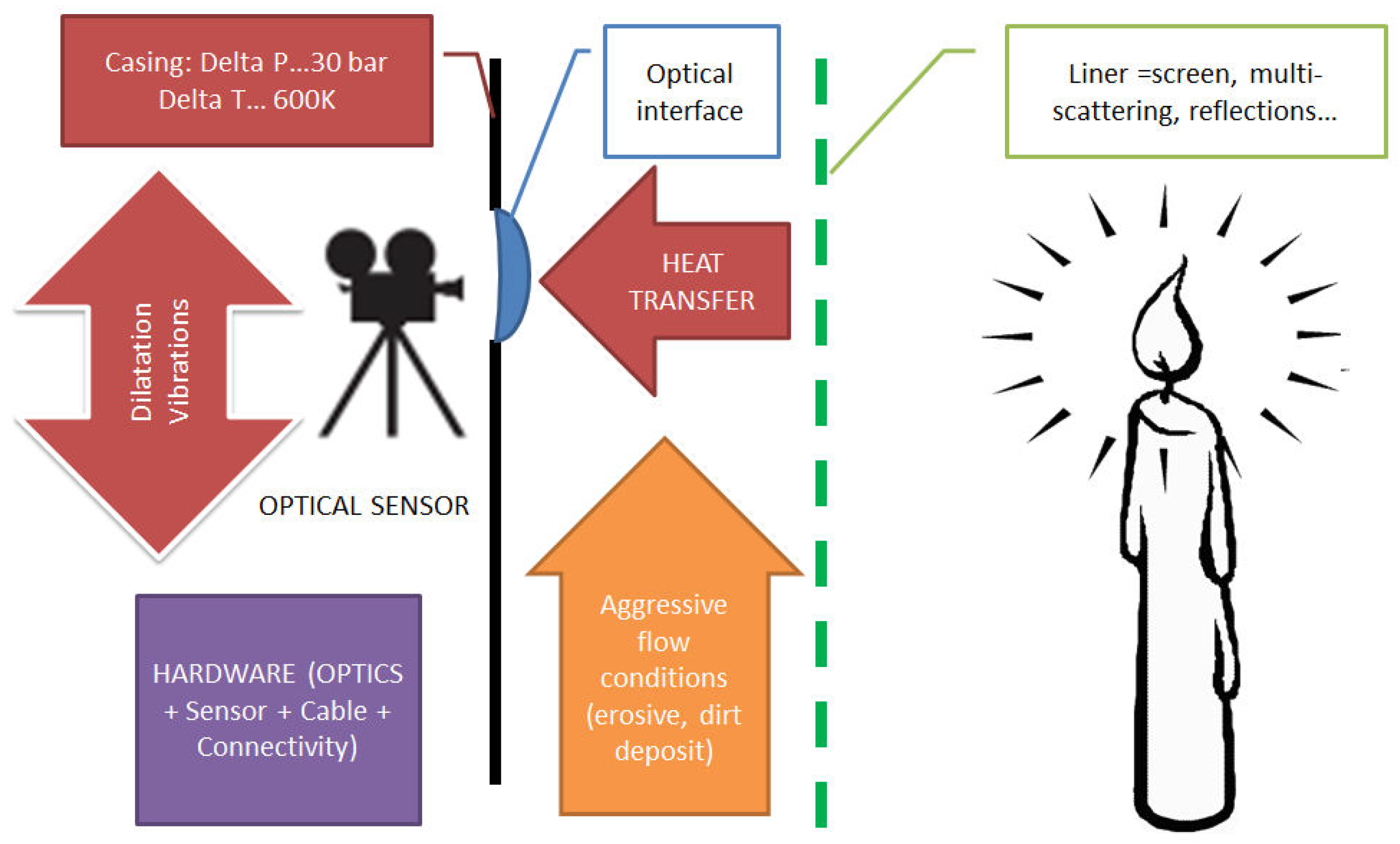
Figure 1 summaries the complexity of including an optical-based measurement technique in the environment of a gas turbine. This is the main reason why this technology has not been deployed yet. First, the optical access is of importance, and the options for a direct line-of-sight access to the flame are very few: through the burner where the instrumentation is placed in the strut, in the burner itself or, more easily, on the external side of the pressure casing while the optical access faces a dilution hole. Other options like indirect light gathering, in front of the multi-perforated liner, for instance, or from reflections are also possible.
The technology makes sense as long as the optical interface is transparent. It is the assumption that, like in an oven, the different dilatation rates of residuals like soot and glass lead to a self-cleaning effect [
7].
The materials chosen such as quartz glass SQ1 are extremely effective in terms of temperature resistance; however, these are brittle, and the last thing one wants is to make a hole in the high-pressure core. The design therefore includes fail-safe strategies, where the probe’s components are contained in case of glass rupture.
The technical choices developed in the following lead us to opting for an actively cooled technology using pressurised air. However, we are confident that after the workarounds performed with the sensors placed as close as possible to the flame; an alternative, e.g., using glass fibre, can be put into place and can reduce considerably the probe size.
2.3. Combustion Monitoring Strategy
A portable measurement chain and a demonstration on a pressurised combustion rig was built to bring this technology to TRL 4 (demonstration level under realistic conditions) including a heat-resistant probe concept.
The idea of the emootion project is to equip a gas turbine combustor with a minimal number of probes combining optical and acoustic measurements for advanced monitoring of the combustion. This technology must describe in a satisfying manner all important operation and ignition regimes of a GT combustor, including the detection and better understanding of possible combustion instabilities. Additional to its role of real-time monitoring, the measurement technique allows to estimate the fatigue with time of the parts and other instrumentation in the hot core.
Using a set of three probes as shown in
Figure 2 on an annular combustor, one can survey the flame propagation from one measurement volume to the next in the longitudinal and in the azimuthal directions. It is possible to survey the presence of the flame and the combustion process from at least three points of view. At last, it is possible to correlate six chunks of information (three times light intensity and three times sound). These signals, when correlated, help to understand the main features of the reactive flow. For instance, from which side does the flame front come during the ignition process or, in case of a combustion instability, is it an axial, azimuthal. or combined mode that dominates the thermoacoustic coupling.
The redundancy aspect is also a fail-safe strategy. The redundancy is ensured by the fact that one probe contains four optical sensors and one fast-pressure sensor and that there are three probes. Should an optical interface be blackened or should any sensor fail, it is unlikely that all sensors meet a malfunction at the same time during normal operation—therefore, minimum information is guaranteed.
3. Sensing Strategy
3.1. Use of Photodiodes
A selection of optical sensors took place in the pilot study [
1], where TRL 2 was met since all the following features could be separately addressed with good success using the same photodiode arrangement. It performed very well in terms of flame/no flame differentiation, ignition sequence description, premixed flame radiative intensity as an indication of thermal power, and combustion instability detection.
3.2. Combination with an Acoustic Sensor
A positive experience was made with a single probe construction combining an optical sensor with an acoustic sensor for all test cases. In the end, we propose a combined, compact, and miniaturised version of the simultaneous optic-acoustic combustion monitoring setup proposed by Fernandes and Heitor [
8]. We called this probe the Rayleigh criterion probe (RCP) [
9]. An appropriate formulation of the Rayleigh criterion can be found in [
10].
Figure 3 is a suggestion of what the final probe can look like, as designed for the aggressive environment of the combustor. The probe tip should be flush mounted on the pressure casing, with a line of sight towards the liner. The flame is made visible through the cooling holes or through the multi-perforated liner. It was also verified in this work that the light reflected by the walls can be used. This is indeed the case, although one loses the notion of a discrete and well-bounded control volume.
Figure 4 depicts the early RCP development stage.
The lessons learned from the pilot study were that the collection of light is essential and is so far a limitation to the use of optical fibre. Therefore, the sensor is placed relatively close to the optical interface, as near as possible to the flame scene, and requires active cooling. This is the reason why miniaturisation of the probe was set to second priority, until the spectrum-defined works are done.
3.3. Chromatic Analysis of Selected Spectral Bands, Currently RGB
Though the term incandescence is mostly related to the presence of soot when related to flames, the term chemiluminescence in the following is understood as including incandescence if any. As mentioned before, one source of artefacts in this technology could be the incandescence of hot glowing parts such as the liner walls, which need to be treated separately or filtered out if possible.
Gaydon produced extensive research about flame chemiluminescence [
12]. More recently, Hardalupas et al. [
6], Panoutsos et al. [
13], and Arias et al. [
14] used selective bands such as the CH* and C
* bands to analyse the equivalence ratio and the quality of premixed flames. In laboratory applications, the OH* radical (UV domain) is used to estimate the reaction rate using planar laser-induced fluorescence (PLIF) [
15]. In the IR range, Manara et al. worked on optical based thermometry in gas turbines [
16]. Note that this last application also requires active water cooling. Based on these works, the original idea was to use interferometric filters and wavelength-specific sensors. However, given the named objectives in terms of probe size and available surface for light gathering, we faced a problem of sensitivity. Furthermore, the different sensors all had different response times, which is a problem when comparing the dynamic combustion behaviour.
The detectable light source is the flame’s chemiluminescence. We are interested at first in a qualitative approach of the flame. Its description is based on the global intensity of the gathered light, and on the intensity for selected wavelengths. The different levels of intensity reveal whether the flame is premixed (strong blue light component) or a diffusion flame (strong red light component).
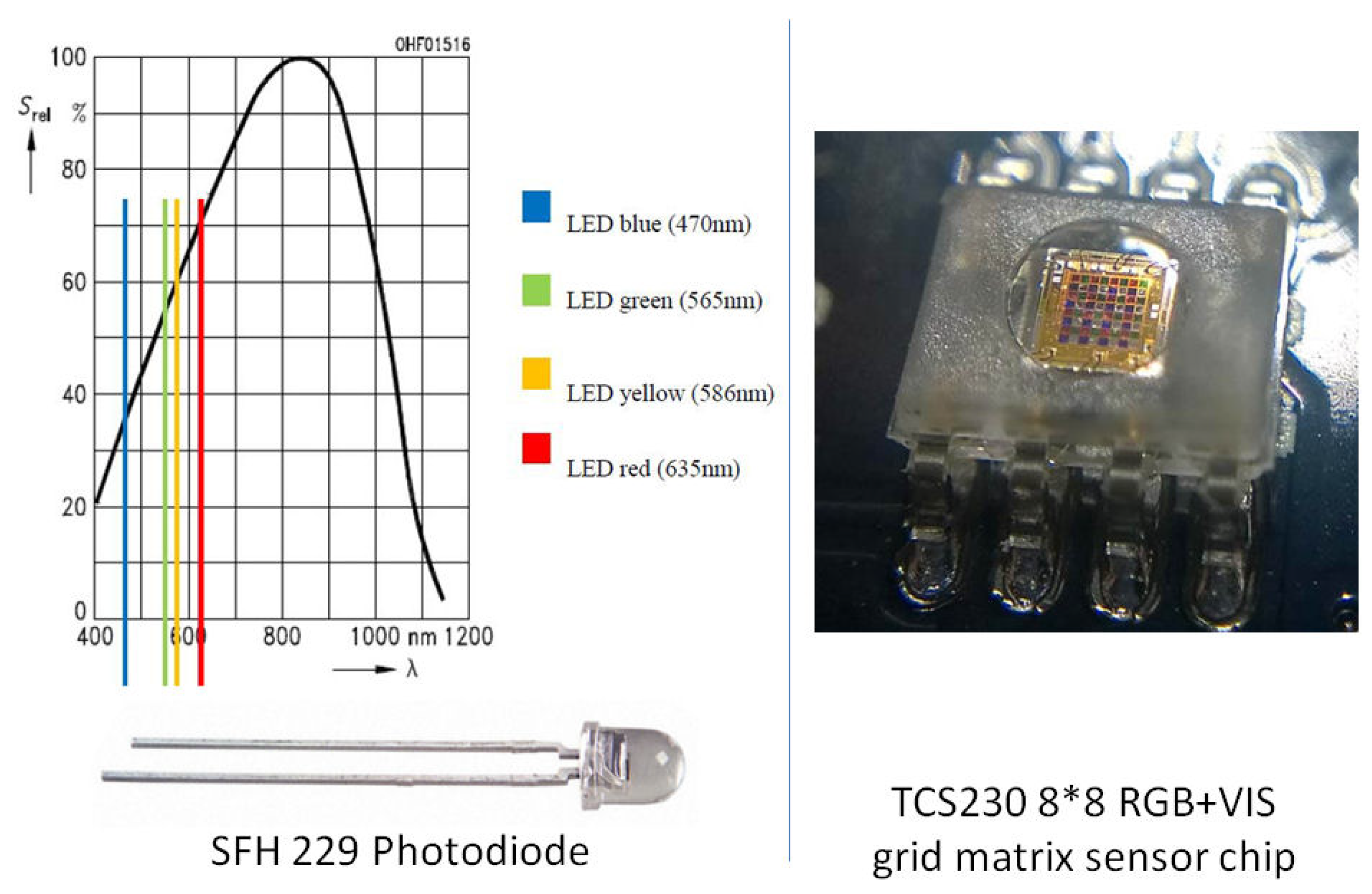
This is the reason why we came back to the original concept using the same broadband sensor and using band-pass filters at first where also problems of sensitivity were met. We opted in the frame of this study for an RGB description of light, which is well-known colour code in imagery and video. Three wavelength-specific sensors are compared to a sensor mounted without filter, named “visible” (VIS) in the following. The sensitivity of the broadband sensor to the varying wavelengths is displayed in top left of
Figure 5. The saturation of the sensor was studied using the PD shown in the same figure. Analysing the RGB contents of the visible light offers an accessible and intuitive approach of flame luminescence. The decomposition of white light using filters in these three additive colours is used since the early days of colour photography, and RGB has become a standard in photography, in video and in offset printing. Positive works using flame RGB coding, e.g., by Huang et al. or Trindade et al. [
17,
18], have encouraged us to adopt this approach for flame characterisation.
The second optical sensor technology path investigated is for sensor and conditioning being fully digital (work in progress) using a TCS230 colour sensor chip. This eventually should be part of the glass-fibre strategy. In both cases, the red-green-blue light components as well as the white spectrum (sum of all visible wavelengths) are addressed. Both optical sensor options can be seen in
Figure 5 regarding the analysis of spectral bands.
The probe benchmarking and calibration procedures are summarised in
Figure 6. The RGB and visible range sensors are compared to each other when submitted to a repeatable source of light (e.g., a halogen lamp with or without photographic filters). It compares the final multicomponent probes with each other for quality assessment. Finally, it foresees self-check procedures. One idea is that each probe includes a small light for self-test at rest.
3.4. Probe Packaging
Considerations were made regarding the packaging aspect of the probe. The target size of the flush-mounted probe, the exposed size to the hot environment, is inch, mounted in a G1/2 port. At first, an uncooled concept making use of a high-temperature-resistant miniature fast-pressure probe was envisioned. The optical interface would couple to an optical fibre to transport the light from the hot environment towards the sensor in a safe remote position. At current status, this solution is not satisfying in terms of signal-to-noise ratio (SNR) at the location of the downstream sensor. Therefore, we came back to a concept with the optical sensor embedded in the probe, thus necessitating an active cooling strategy.
One major insight from the pilot study was that the collection of light especially at low intensities is highly essential, which is so far a technical limitation for the use of optical fibre for light transmission. Therefore, the probe’s sensor is placed relatively close to the optical interface, as close as possible to the combustion location where active sensor cooling is required. Thus, the current probe model is mounted in a G1 port. The early sensors and signal conditioning were analogue using a photodiode-type SFH 229 and photographic filters. The optical broadband PD sensors were used with band-pass filters at first (e.g., filter-type Brightline fluorescence filter 440/40), where also problems of sensitivity were met. In the end, coloured Kodak Wratten Gelatin Filters (as used in photography) were used in blue, red, and green, with a Gaussian band-pass of 100 nm three filters, centred at 430, 530, and 630 nm for blue, green, and red, respectively. Since at a later stage, it is intended to use selected bands including the UV (e.g., OH* radicals) and the infrared (soot), attempts were made with band-specific sensors. However, the differences in technologies, sensitivity, and time response brought us back to a uniform, all-rounder solution using the same photodiode with optical RG and B filters.
4. Probe and Test Rig Designs
4.1. Combined Optic-Acoustic Probe Design
Figure 7 shows the high-pressure-and-temperature-resistant RCP. A fast pressure transducer is placed in the middle (model CP232, 800 pC/bar, from Meggitt Sensing System, Fribourg, Switzerland). The high-temperature fast-pressure probe equipment is the measurement chain presented in paper GT2016-56166 [
19]. The large optical interfaces that surrounds it is made up of quartz glass SQ1 and was casted for this purpose. Its conical shape allows to resist the strains better due to the dilatation of the metal part. The depth ensures a temperature stoppage so that the air-cooled optical sensors placed behind can operate below 80
C. The sensor board is a Polyamid (PA) part produced with additive manufacturing. It holds the sensors and filters in place, organises the cabling, and distributes the cooling air that flushes the sensors first and the hot surfaces second. Due to the stacking effect, the same part is designed to contain any piece of glass as well as the pressure probe in case of glass rupture. The sealants are high-temperature mortar in the front and high temperature adhesives in the rear. Future versions will include a sapphire glass mounted in the metal frame of the probe, possibly shaped as a Fourier lens to maximise light gathering (see also
Figure 3).
4.2. Test Burner, Model CBO4
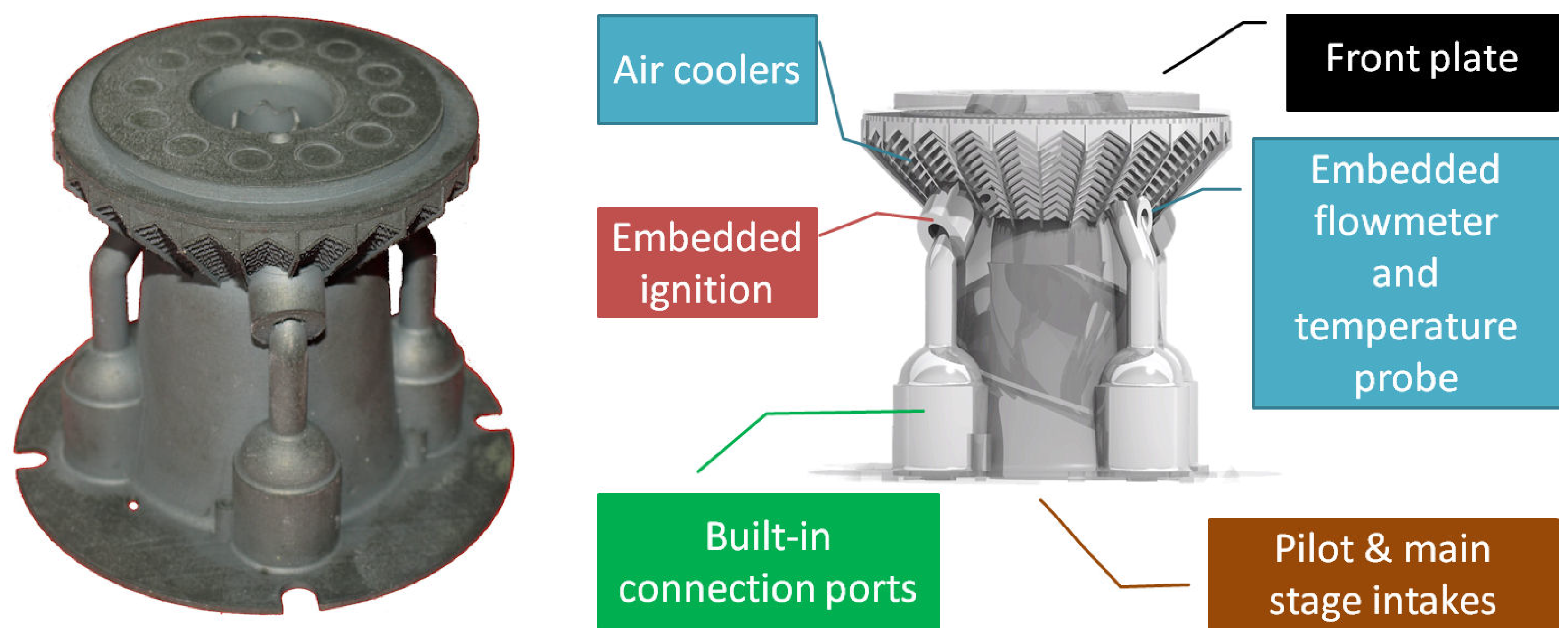
The air-propane premixed 2-stage burner used in this study (
Figure 8) was presented in paper [
2]. It was realised using additive manufacturing, testing and validating new methods for fuel injection and mixing, and onboard instrumentation.
The combustion chamber features a two-stage concentric burner, where the pilot stage is in the middle of the main stage. The performance of the burner is described at room conditions in
Table 1. The global swirl number is estimated near 0.9 using a SIMPLE-algorithm simulation on the steady-state cold flow using openFoam (Mokalled et al., 2016 [
20]). The aspect ratio between the resulting flame and the estimated reactive mixture placement using the simulation was found satisfactory, so that the flow patterns and their order of magnitude could be realistically produced (
Figure 9). The lower contours show the cup-like injection of the reactants (potential core contour at 6 m/s axial speed) plus detail of the internal recirculation zone.
4.3. Pressurised Combustion Rig
The experimental setup for validation of the emootion probes consists of a gas-powered (propane C3H8, type UN 1965 mixture C, 46.3 MJ/kg, 2 kg/m
at standard conditions), intermediate pressure test rig featuring a siren actuator. Early tests were conducted on the MethaNull test rig [
1,
21].
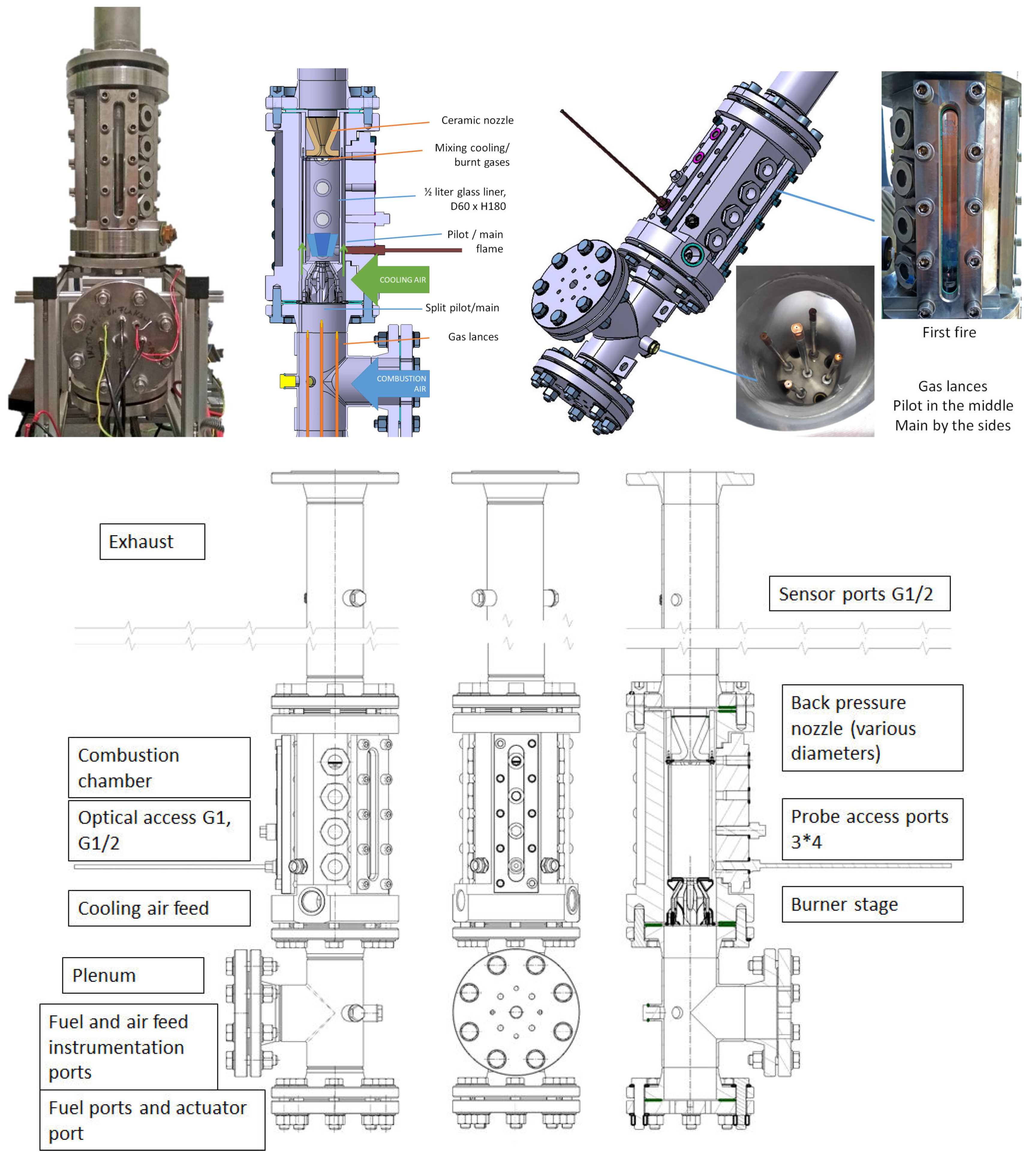
Following to this, a new pressurised combustion test rig was designed for the specific purpose of the emootion project. This mock-up is situated in the technical facilities of FH JOANNEUM/Aviation. Based on the MethaNull combustor, it consists of a single-sector combustor equipped with the CBO4 burner. It is air cooled. The first fire took place in the summer of 2019.
Figure 10 shows the structure of the facility, a head-up construction where plenum, combustor, and exhaust are in-line. The pressurised air entering the plenum is split into burner air and cooling air, with a ratio of 1/5–4/5. The flame is confined in a cylindrical high-temperature glass (borosilicate) of dimensions D*h 60 × 180 mm. It is therefore expected that only the “burner air” is involved in the combustion. The hot gases are gathered in the dilution cone. For these experiments, sets of 10, 8, and 6 mm nozzles in the exhaust were produced to build up the pressure in the vessel.
The performance of the rig is presented in
Table 2.
4.4. The Siren Actuator
To perform reproducible dynamic tests on the test rig, a siren actuator is coupled upstream to the combustion chamber. A siren model CBOne-3G (Combustion Bay One e.U., Graz, Austria) is used to initiate and sustain a controlled combustion instability by meeting an eigenfrequency of resonance involving the flame and the acoustics of the rig. This device involves a sonic air jet chopped by a fast rotating cogged wheel, thus pulsating the flow. A complete description of the apparatus and of the test procedures can be found in Reference [
3]. The siren was operated from 0 up to 2400 Hz, generating sound pressure levels via the flame up to 132 dB Sound Pressure Level (SPL) for the results shown in this study and 150 dB SPL reported in the previous reference.
In the following, the siren is mounted in blow-down or in discharge mode, as shown in
Figure 11. The two types of actuation are effective, the discharge mode being more likely to be used on power gas turbines because it would derive a part of service air redirected as cooling air after the first transonic turbine stage. In the case of the discharge, all of the burning air (summing up the pilot and main air feeds and not including the cooling air) flows through the siren.
4.5. The S3R Ignition System
A detonation-free ignition device was further developed in this project in order to provide a safe, smooth, smart, and reliable flame start (therefore the acronym S3R). The origin of this device relates with works on the success rate of conventional ignition [
22] and on the safety needs to avoid at all costs a detonation in a test cell with an optical access. The whole principle is based on the control of a premixed ignition flame, with thermal power of 0.5 kW.
This device could be validated during the measurement campaign under atmospheric as well as under intermediate pressure conditions. It was made practical for use for the validation aspects of the RCP probe regarding the monitoring of ignition success as well as the repeatability of ignition sequences.
The ignition unit contains an air compressor; a propane canister; a high-energy spark capacitor; a set of valves with pressure sensors; and a microcontroller that allows manual, semi-manual, or automatic ignition sequence. Air and gas mix in a feed tube that goes to the CBO4’s side igniters, where the tungsten sparkler is situated. The whole operation is surveyed by a flame detector, supposed in the end to be the RCP. The ignition unit is used for protection—it is prevented from firing if it calculates that too much reactant was injected in the combustor, blocking all fuel feeds for a given flush duration. The ignition sequence of the CBO4 is shown in
Figure 12.
4.6. Support Instrumentation
The measurement chain includes an industrial unit connected to the fast pressure transducers similar to the equipment discussed in Reference [
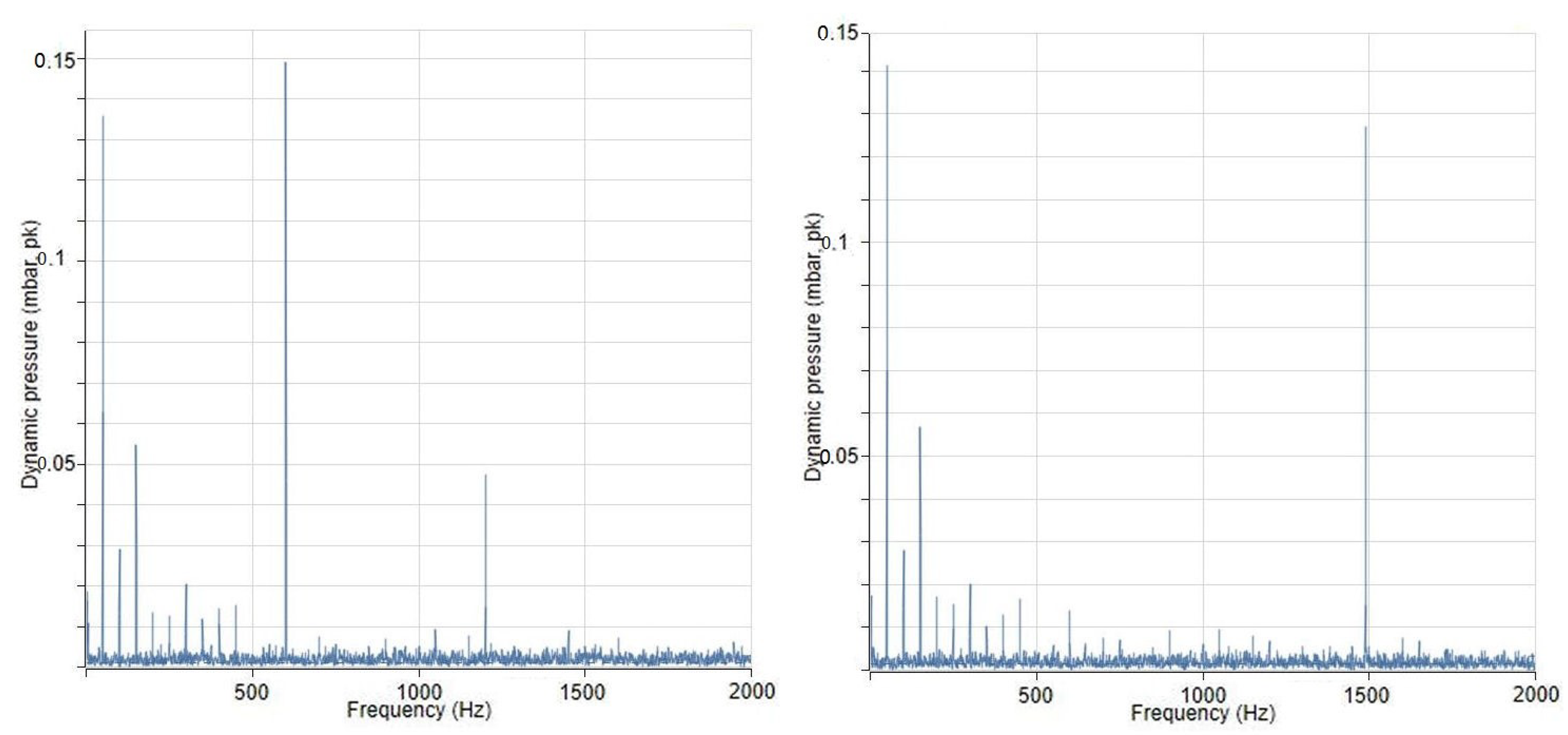
19]. In this experiment, the fast pressure transducers CP232 with a sensitivity 800 pC/bar are acquired with 5 kHz per line coded in 24 bits, connected to a VM600 rack including a XMV16/XIO16T card pair. The acquisition software is VibroSight version 4.1. All elements cited are part of the Vibro-Meter measurement chain (MEGGITT, Fribourg, Switzerland). Two separate measurements are shown in
Figure 13.
In order to avoid a possible crosstalk from the fast pressure transducers or from the siren’s TTL synchronisation signal, the acquisition of the PDs is done and grounded separately in a first attempt, with the intent to merge both measurement chains at a later stage on the sole Vibro-Meter chain.
As in paper GT2017-63626 [
1], the PD signals are analogue, raw, and unamplified. The optical probes are therefore connected to a DAQ1208FS from RedLabs (MeilHaus Electronic, Alling, Germany), with the visual signals fully acquired, and the RGB components are multiplexed and then de-multiplexed in an attempt to condense the data streams and limit the data storage.
4.7. Installation of the Probes
The first tests are atmospheric. The flame is present within the glass liner but without a pressure casing. The burner is mounted with its quartz glass liner only. Three probes are mounted at the burner as for the multi-probe concept shown earlier.
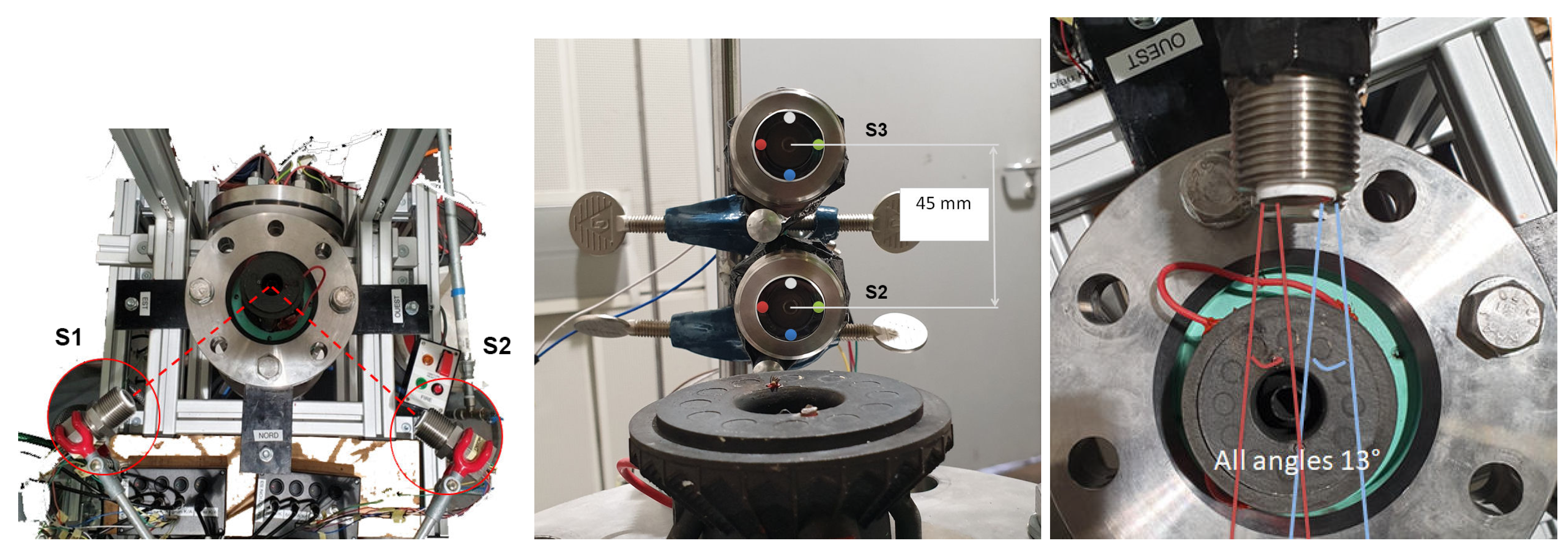
Figure 14 shows the placement of the Rayleigh Criterion Probes on the test rig. The S1 and S2 probes are placed at 120 degrees from each other, their centerline 15 mm above the front plate. These two observe the flame primary zone. Probe S3 is placed 45 mm above S2 and observes the flame’s secondary zone. In the following, the distance from the optical interface to the burner’s centerline is 40 mm, as it will be when mounted in the casing.
The optical interface is such that the sensor having originally a 17 degrees solid angle of vision is reduced to 13 degrees. The characterisation was realised by manoeuvring a laser beam along one axis of the probe. Therefore, it is confirmed that the optical system is directional. Furthermore, this arrangement suffices to know from which direction a beam of light is coming from. In other words, a single combined probe should be able to detect from which side the flame front is coming from at ignition.
5. Experimental Results
5.1. Atmospheric Tests: Confined Flame in the Liner Only
The flame is present within the glass liner but without a pressure casing. The burner is mounted with its quartz glass liner only.
The burner is operated from very lean burn at the Lean blowout limit (LBO) limit to slightly rich conditions (see
Table 3). The liner is manufactured of glass. There is no secondary air flushing the exhaust gases right after combustion. Therefore, soot appears early in the corner recirculation zone and right after the primary zone due to the lack of oxygen. An indicative equivalence ratio is computed based on the inlet mass flows of air and fuel gas.
Three RCPs were produced and assessed comparatively. The test cases of interest were as follows:
the differentiation of flame/no flame;
the ignition sequence and eventually the ignition success;
the type of operation, from premixed flame to diffusion flame, regarding the aspect operation point and soot detection; and
the flame stability.
As previously mentioned in the subsection on test rig operations conditions, all four burner operational cases of interest are examined.
5.1.1. Monitoring of the Ignition and Flameout
In
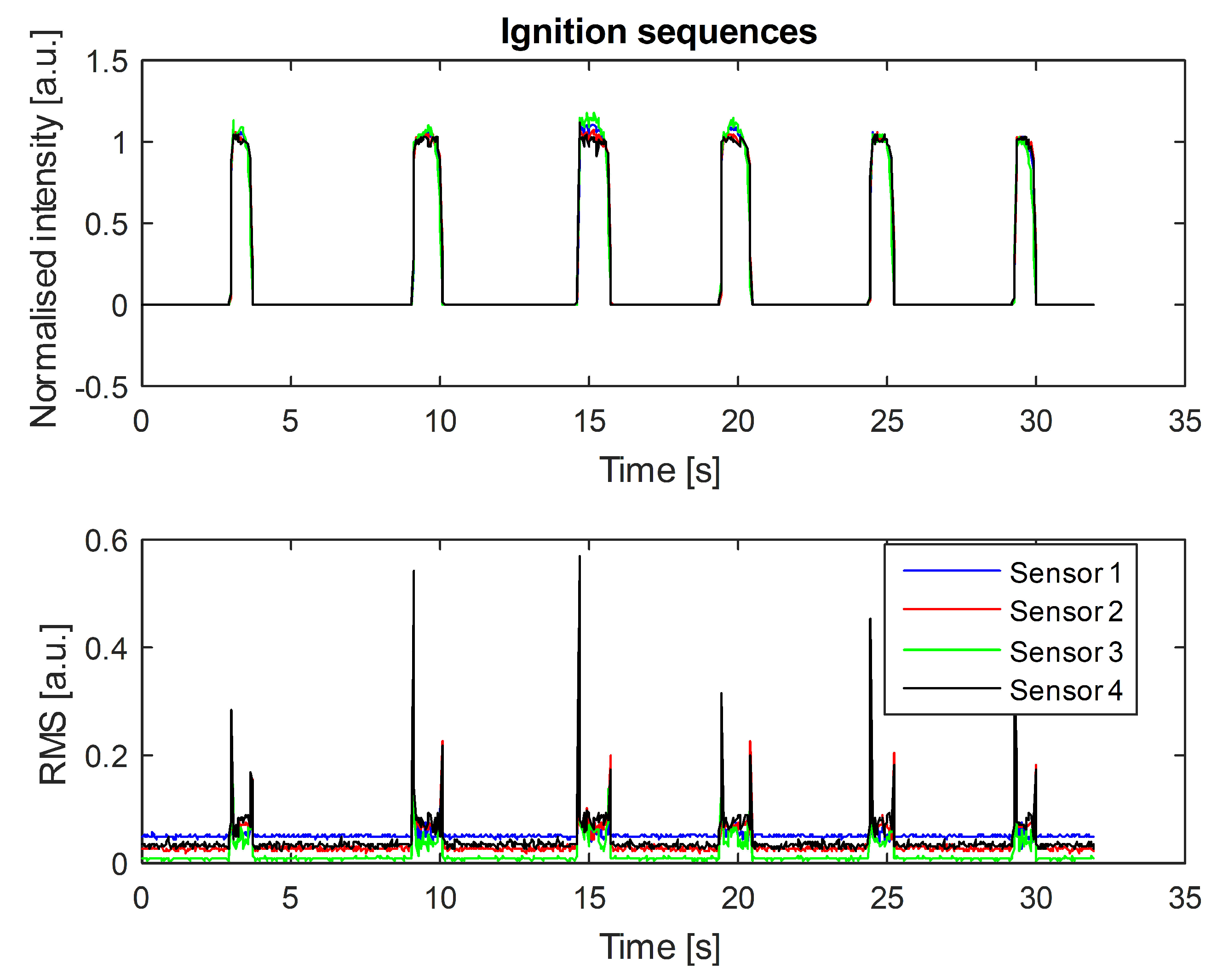
Figure 15, the four PDs report on a repeated sequence including an ignition followed-up by a flame extinction. For this experiment and to protect additional equipment, an ignition device using a glow plug was used to avoid electromagnetic disturbance of a spark. All amplitudes are normalised in the upper plot. In order to detail which sensor responds first and comes back with information about the flame propagation, the best method found is an analysis of the sensor’s RMS using a windowing of 0.04 s as shown in
Figure 15 below. Provided that the ignition sequence is well-repeated, then the engine start-up monitoring performs well. If deviations are observed, this would then be a maintenance indicator.
5.1.2. Digital Photography
The probe measurements are compared to the analysis of a series of pictures produced with a digital reflex camera in manual mode with fixed ISO sensitivity and aperture (camera Olympus E-410, objective 50 mm, 10 MP CMOS sensor with an aspect ratio of 3/4, 8-bit nonlinear colour coding in sRGB format for JPEG pictures).
Sets of pictures were taken randomly using the same settings, chosen to take advantage of the full 8-bits scale from the least visible (3.8 kW, lean flame near LBO) to the most radiant one (9 kW, diffusion flame) without reaching saturation. The mean intensity and the RMS are computed pixel-wise over a series of pictures. It takes at least 25 frames to get a converged RMS value. The series shown in
Figure 16 were therefore done with 50 shots per operating point.
Three operation points are compared. For each of these, the interrogation area is the full frame, the zone observed by the probe mounted facing the primary zone, or the one observed by the second probe in the secondary zone.
The average and standard deviation intensities of each R, G and B components are displayed, as well a the grayscale component VIS. VIS is computed after a weighing of the measured RGB intensities per pixel so that VIS=29.89% of R + 58.70% of G + 11.40% of B. This function is used in photography by eliminating the hue and saturation information while retaining the luminance.
The analysis confirms the intuitive approach: A premixed propane flame is mostly blue, and red can become the dominant colour component in diffusion flames. While the average green is very comparable to the visible component since dominant in the weighing, its RMS-to-mean ratio is greater than the blue one in most of the premixed flames analysed. The analysis of the green component is therefore of importance.
The intensity ratio blue/red is an indicator on the flame regime and can be used to situate the transition from premixed to diffusion based on the sudden rise in red component.
The intensity evolves linearly as long as the flame is premixed, with a change in slope in the presence of a diffusion flame, as expected. The location of the probe in the secondary zone for soot observation definitely makes sense, while the one focusing on the primary zone only could make a different interpretation of the flame.
The results of photography performed on the pulsating flame are not shown. Since the time of exposure of this method is most of the time longer than the periods of pulsation, the pulse flame details could not be caught in an image. This would require equipment such as light intensifiers or Schlieren approaches outside of the frame of this study to specifically address these aspects. However, one hypothesis was that the outer boundaries of the flame might be specific to the region of resonance and that a combustion instability could be identified based on the time average shape of the flame. Therefore, combustion instability detection with this method must rely on highly time-resolved signals.
5.1.3. RGB-Based Monitoring of the Flame Operation
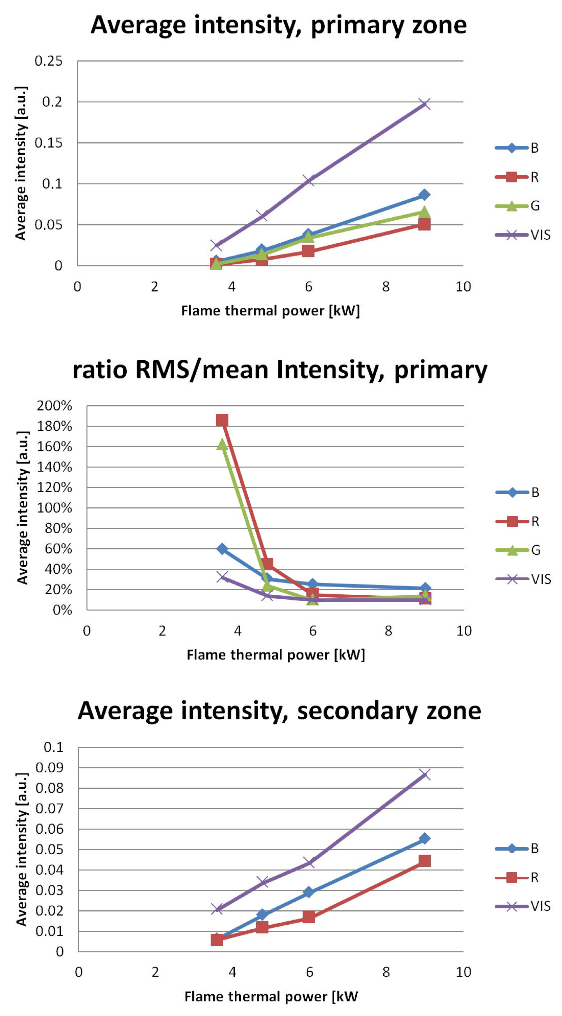
The RGB measurements performed by the probes in the primary and secondary zones of the flame are displayed in
Figure 17. The three components of light are measured, as well a the visible component. It was verified that the visible component is in good agreement with the weighing discussed previously (results not shown). All in all, the probe measurements meet the trends established by the photography session in the primary and secondary zones. The intensity is a good indicator of flame power. The differences occur due to the specific obscuration of each used colour filter. This explains why the blue component remains the most observable in all cases, although the sudden change in ratio of blue/red is a strong indicator for the presence of a diffusion flame.
The ratio of RMS/amplitude drops down to the range 10–20% when the flame achieves nominal power, which matches the order of magnitude of turbulence measured in comparable flows [
23]. The strong ratio RMS versus average near the LBO can therefore be used as a reliable flame detection operator when the SNR of the PDs is low.
5.1.4. Detection of Combustion Instabilities
The SFH 229 diode combines a high sensitivity with a very short response time. Tests with a high-frequency stroboscope (see
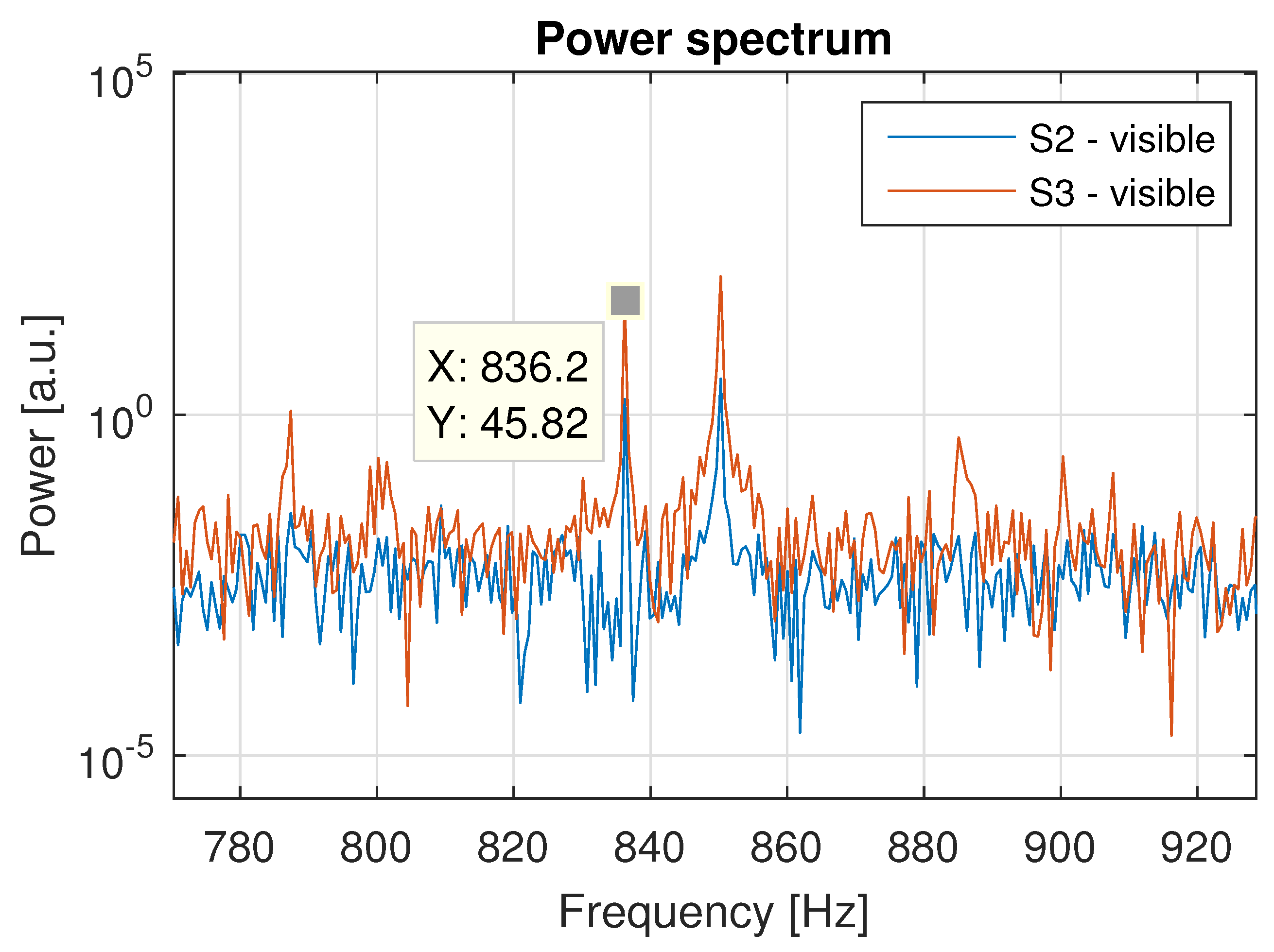
Figure 6) showed a cutoff frequency of the sensor beyond 8 kHz. The highest frequency at which a coupling between the flame and the acoustics of the flow was observed directly on the spectra is 836 Hz, as shown in
Figure 18, while peaks in sound intensity were recorded up to 2400 Hz (see the comparison with the pressure test below). The explanation offered is that, due to the angle of view of the optical device combined to the speed of the flow and the period of excitation, the measurement techniques meet under these flow conditions their cutoff frequency (a form of the Nyquist–Shannon sampling theorem: A flame oscillation with a period smaller than twice the measurement length is no more observable). This speaks for the least possible solid angle of vision. However, this cutoff effect is hardly avoidable due to the quantity of light that must be gathered, and the domain 0–1 kHz covers the high-energy pulsations. Nevertheless, the pressure tests presented at the end of the paper suggest another way to identify thermoacoustic coupling at higher frequencies using the same setup.
5.2. Pressure Tests
5.2.1. Siren in Discharge Mode: Differentiation No Flame/Premixed Flame/Diffusion Flame
For all pressure tests, the similarity is based on the adjustment of the Air-to-fuel ratio (AFR) of the premixing in the pilot and main stages to make comparisons based on a similar equivalence ratio, the reference being the atmospheric conditions of
Table 1.
An early test was produced at 2.3 bar abs on the MethaNull setup using the same burner. This combustor has a single-burner sector confined in a 200 mm diameter round section. More details are presented in Reference [
21]. The critical nozzle diameter at the combustor’s outlet is 6 mm; this is needed to build up pressure in the test facility up to 2.3 bar bas. In that case, the siren pulsator is built in discharge mode, equipped with a 5 mm critical nozzle and pulsated in all-or-nothing mode (a more detailed version of the same experiment is reported in [
3]). In order to guarantee an elevated mass flow in burning air, directly related to the reference velocity
, the siren is sampled from the pressurised plenum, with special care that, under no circumstances, fuel leaks (a gas detector was used in the atmospheric section of the siren, and for safety measures, the sampled air was redirected in the hot stream in the chimney). In this test, an early prototype of the RCP probe was used, where the RGB sensors were facing a window and a microphone was placed in the plenum. The specificity of this test was that the acquisition on the microphone and on the optical sensors were done using two separate acquisition systems to avoid crosstalks. Using this configuration with the siren in discharge mode, a successful observation of a combustion instability could be observed as reported in the same reference [
3].
For this plot and the following, the light intensities are normalised as follows. The DC offset versus sensor average status at rest is subtracted, and the result is divided by the RMS of the same reference signal at rest. This is done for all visible and RGB channels.
The power settings in this test are detailed in
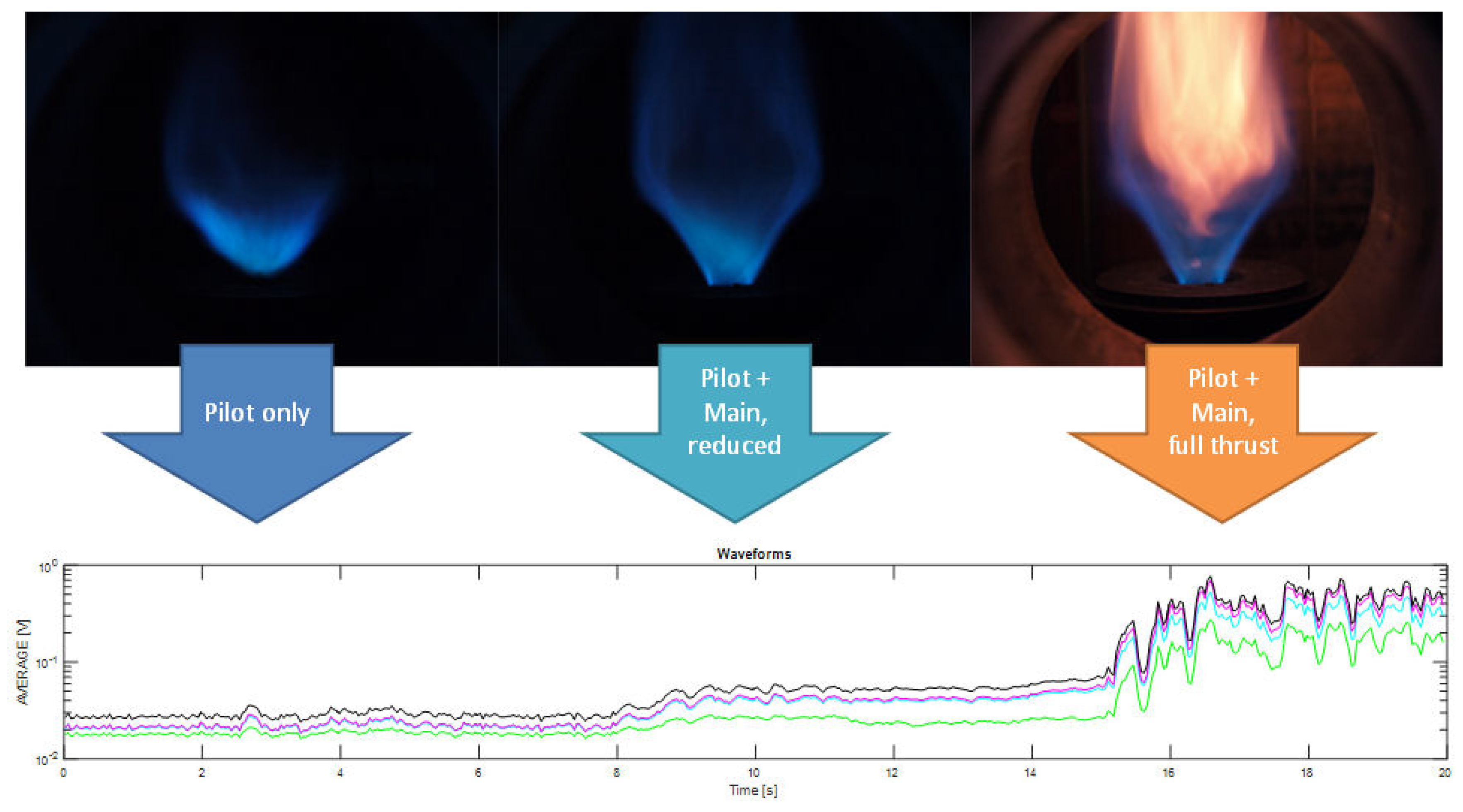
Table 4. Three situations are described. First, the pilot flame only is detached. Second, the main flame is turned on and attached. Third, the main gas flow is increased by keeping the air constant so that the flame becomes diffusive and, hence, radiative. The light intensity corresponding to different power settings of the burner is reported for the RGB and visible components in
Figure 19. This reproduces well the observed trends of increasing average intensity seen under atmospheric conditions and reported previously in
Figure 17.
While the flame thermal power ranges from 1 to 4 from left to right, the radiative power ranges from 1 to 72. The light intensity of combustion flames was also measured with a photometer (model RS PRO LED Light Meter), where luminous flux was measured according to the power settings (as of
Table 4) in relative quantities of 0.25 - 1 - 18 Lx, in fair adequacy with the RCP outputs. This ratio is correlated with the actual diode measurements. Regarding signal processing, it is important to keep in mind that, while the thermal power is augmented in the single-digit domain, the light intensity responds from single up to the 3-digit domain. The aspect flame/no flame differentiation could be validated by all channels. The verification of the linear relationship between thermal power and radiative intensity in the premixed case (Hardalupas et al., 2004) [
6] could be verified as long as no diffusion flame appears. The obvious change of ratio was observed in the diffusive case. Finally, information about the flame turbulence could be observed and the distance between two sensors on the same probe could be used to determine the direction of moving coherent flame structures.
5.2.2. Blow-Down Mode: Ignition Tests
In the following, the siren was built in blow-down configuration using the new combustion rig presented in this paper, where all of the burning air flows first through the siren position upstream from the plenum (see
Figure 11). The chosen siren slot nozzle of 20 mm
allows excitation frequencies up to 6 kHz. However, due to the low critical section of the siren nozzle and the amount of burning air, the pressure is choked. Using a 10 mm diameter nozzle at the test facilities’ outlet, the tests were performed at 1.4 bar abs in the combustor. Tests are performed on the pilot flame only ranging from 4.25 kW via 5.1 kW to 5.95 kW. The reported combustion instability tests are at 4.25 kW.
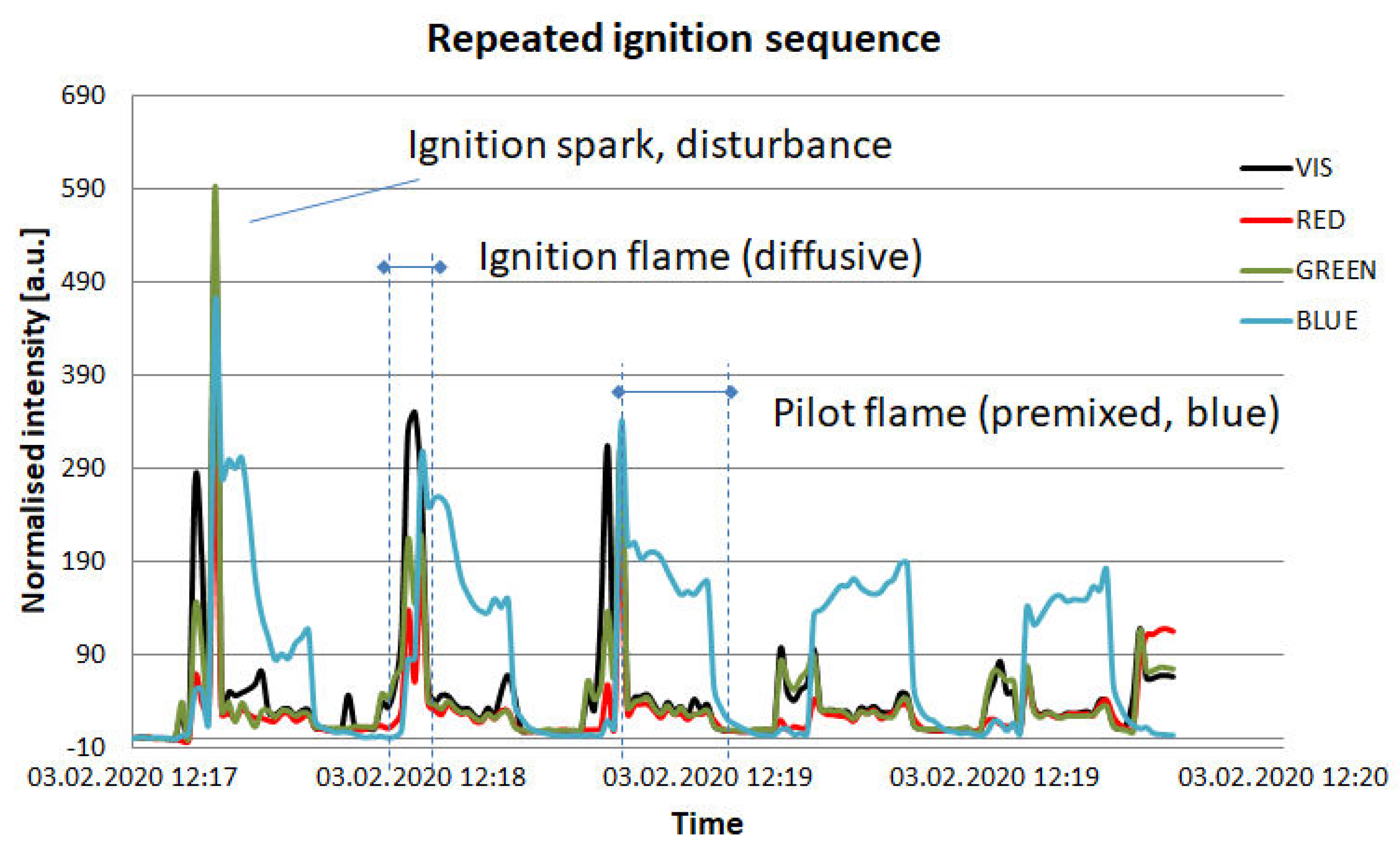
The repeated ignition sequences in
Figure 20 reproduce the pattern observed previously with the ignition under atmospheric conditions (
Figure 15), with the difference that the sequence includes the start of the pilot flame. The sequence reproduces several times the images labeled 1 to 3 from
Figure 12. The explanation offered for the change in patterns through the sequence is that the chamber warms up progressively, facilitating the ignition with time.
5.2.3. Blow-Down Mode: Thermal Power
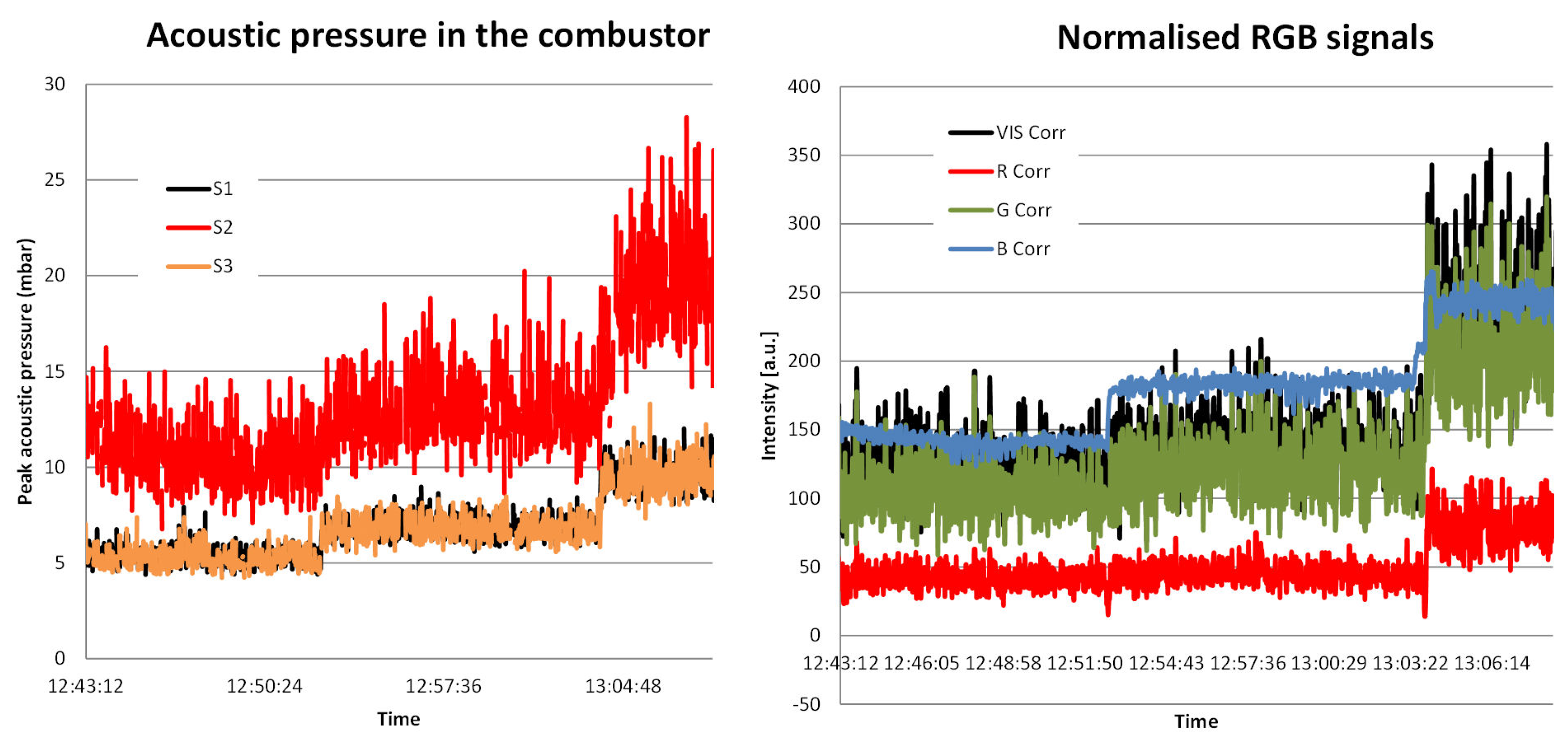
Figure 21 reports on three power levels of the pilot flame in premixed mode. The three RCP probes are mounted on the pressure casing of the combustor and arranged as in
Figure 14 with the difference that S1 and S3 face each other. In the meantime, the optical signals of S3 are displayed.
Quasi all signals—apart from the red component of the flame—show clearly the three levels of power. The signal with the strongest average and RMS levels is the fast pressure one of probe S2. The explanation offered is of acoustic nature, where this location could be situated closer to a standing wave belly than the two others, or of thermal nature, since wall cooling is less effective at the level of S2, situated further down the flow. The pattern measured by the optical sensors are in good agreement with those presented before at atmospheric and at 2.3 bar abs.
5.2.4. Blow-Down Mode: Combustion Stability
We discussed earlier that no clear peak on the light signal is visible when pulsating the flame beyond 900 Hz. We suggested that the angle of light collection becomes too wide to discern single shape changes on the flame.
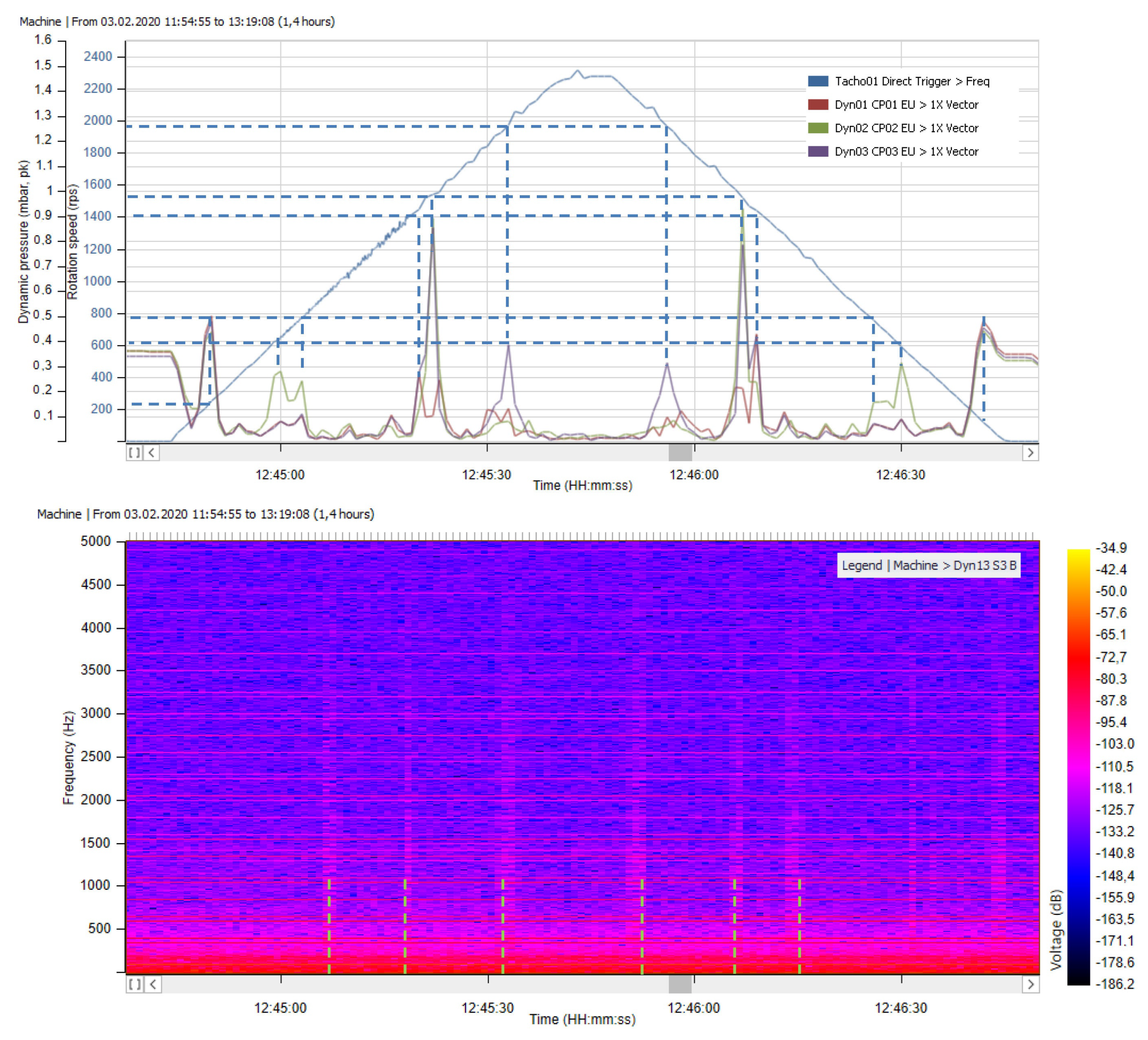
Figure 22 investigates the frequencies 0–2.4 kHz with fast pressure probes and with optical probes (they all report the same information with different details of sensitivity; we chose to show only the blue component).
What is remarkable is that the spectrogram of the blue components shows energy pedestals that match resonant frequencies in the 800 Hz plus domain. The offered explanation is a strong dynamic of the flame at these resonant frequencies that lead to flame surface wrinkling, deforming the flame and making it more compact with a stronger density of thermal energy (as described in References [
9,
21]). This could explain the clearly marked pedestals at frequencies 790, 1420, and 1990 Hz. Additionally, a peak observed around 1200 Hz of second importance on the acoustic side seems to resonate on the optical side.
This method of identification based on the analysis of the spectrogram is promising regarding combustion instabilities. The precise peak-seek-and-hold at the excited frequency might not be necessary and the signal’s averages and higher RMS related to a strong flame deformation might suffice, which would greatly simplify the real-time signal processing.
5.3. Work-in-Progress and Future Developments
Upon reaching a higher TRL on the RCP, multiple sets of RCP will be installed onto GT such as depicted in
Figure 2. The dedicated standalone evaluation unit should be powerful enough to process data delivered by these RCP. Additional to the spatial placement of the probes for quantifying combustion modes, wavelength-specific optical sensors will also be deployed to detect combustion radicals such as OH*, soot, or CH*. The measurement system shall give precise information about the current combustion conditions in a GT in real-time.
About the optical signal pre- and post-conditioning, thoughts are being made about an adaptive light signal amplification that would work as an electronic diaphragm. Emphasis is put on the differentiation flame/no flame even in the case of a very low radiative flame near the LBO and, on the other hand, the capacity to analyse strongly diffusive flame without ever saturating.
Regarding the portable measurement chain using a microcontroller, one major issue on the measurement technique side of the probe design is signal crosstalk. Due to the high sample rates of the signals of interest and the different signal intensities, we have been experiencing cases of undesired signal transformation on independent signal lines in the integrated system. Further effort needs to be put into decoupling of electronic devices, and as a first measure, the operation of the PD in reverse-biased mode and keeping the signal powers in the same order have already been done.
The short-term efforts will focus on auto-tuning and self-check procedures, smart amplification of the signal to adapt the different kind of flame exposures, and flame operation mapping, including soot measurements with the smoke spot test technique according to the standard DIN 51 402. We will progressively augment the pressure and temperature constraints to get closer to real operating conditions in a gas turbine. The question of the robustness of the optical probe versus pressure, heat, and vibrations will constantly be readdressed. Designs tentatively involving an optical interface that conditions the gathered light and in the meantime plays the role of an heat barrier as validated by these works seems to be the most promising. Future designs including optical fibre, no active cooling, and a remotely placed digital chip are a separate work-in-progress. There is also the challenge of the probe’s size. If the current size is compatible with power applications, it needs to be reduced for airborne application. A similar probe with a diameter around 10 mm is envisioned.
6. Conclusions
The experiments reported in this paper confirm the capacity of a discrete instrumentation combining optical and fast pressure sensors to perform detailed combustion monitoring. This is desirable in view of more performant propulsive gas turbines using tighter management of the safety margin.
The placement of (at least) three independent RCPs onto the specimen combustion chamber makes sense since it offers redundancy in case of a single sensor failure. The cross-correlation of the signals describes the flame operation and offers precious information about the flame dynamics.
The RGB flame description gave promising results. This technology is feasible as such for industrial burners. One problem for GT combustor is the glowing of the liner, which needs to be filtered out. This will be considered with metal liners on our test-rig, possibly additively manufactured. The burning of kerosene will also necessitate a similar approach for calibration and chromatic mapping of the flame operation.
The methods using a siren to force a combustion instability were effective. The particular case involving a periodic air discharge from the plenum has been validated during these experimental sessions and will be perfected in the near future. This method for effective flow control seems promising for a use in power gas turbines.
The work-in-progress and future developments focus on confirming and extending the results under atmospheric conditions on the operation range of the new rig. The first pressure tests are convincing. The new test rig introduced in this paper will give the possibility to visit combustion pressures up to 4 bar. Long-duration tests (meaning a 4-h-long sequence) on steady operation and transients will take place at always higher powers, meaning higher thermal stress and higher pressures. A know-how will be gathered under various conditions on the combined acoustic-optic (multi-component) probe.
The goals of the project emootion have been met. As expected, a good agreement is found between the atmospheric tests and the pressure tests, and the expectations on the capacity in terms of monitoring, in terms of detection, in terms of detail, and in terms of sensitivity are fulfilled. The proposed combined acoustic-optic flame monitoring makes definitely sense, and its industrialisation phase could start anytime.
7. Patents
A patent on the emootion probe and combustion monitoring concepts was filled as follows:
Giuliani, F., and Andracher, L., 2018. Sonde und Verfahren zur Überwachung von Verbrennungsvorgängen und/oder eines Zündprozesses (Probe and method for monitoring combustion and/or ignition processes), Sept. 15. Patent registration AT 519720, Patent number A50160/2017.
A patent on the functionalities and design of the CBO4 burner was filled as follows:
Giuliani, F., 2019. Verfahren zur gleichmäßigen Verteilung von Treibstoff und Oxydationsmittel (Process for the uniform distribution of fuel and oxidizer), June 6. Publication of the patent registration pending, ref. A50516/2019.
Author Contributions
F.G.: conceptualization, methodology, supervision, and writing. L.A.: supervision, experimental research, and laboratory curation. V.M.: hardware design and experimental research. N.P.: experimental research, data acquisition, and processing. A.H.: computational fluid dynamics. All authors have read and agreed to the published version of the manuscript.
Funding
The collaborative research project “emootion” was supported financially since 2015 by the FFG (Austrian Research Promotion Agency) and by the BMVIT (Austrian Federal Ministry for Transport, Innovation and Technology). The project about “Engine health monitoring and refined combustion control based on optical diagnostic techniques embedded in the combustor” was supported by the Austrian grant for applied research in aviation called the “Take-Off” program, contracts 850470 (emootion, 2015–2017) and 861004 (emootion, 2017–2020).
Acknowledgments
We hereby wish to acknowledge all parties that expressed an interest in this project from its basic concept to its transformation. Special thanks to our colleagues from SAFRAN, from PIEZOCRYST (LOIs), from HEIDECO (Test rig manufacturing), from JOANNEUM RESEARCH (AM Burner), and from the FFG (our project officers from the Take-Off programme as well as from the PatentScheck programme).
Conflicts of Interest
The authors declare no conflict of interest.
Abbreviations
The following abbreviations are used in this manuscript:
| A | (m) | Area |
| AFR | (-) | Air-to-fuel ratio, by mass |
| AM | | Additive Manufacturing |
| CBOne | | Combustion Bay One e.U. |
| emootion | (project acronym) | Engine health MOnitOring and refined combusTION control based on optical diagnostic techniques embedded in the combustor |
| FHJ-IAV | | University of Applied Sciences FH JOANNEUM GmbH—Institute of Aviation |
| GT | | Gas turbine |
| IR | | Infrared |
| LBO | | Lean blowout limit |
| LP | | Low pressure |
| PA | | Polyamid |
| PD | | Photodiode |
| RCP | | Rayleigh criterion probe |
| RGB | | Red green blue |
| RMS | | Root mean square |
| SNR | [-] | Signal-to-noise ratio |
| SPL | [dB SPL] | Sound Pressure Level |
| S3R | | Safe, Smooth, Smart & Reliable Ignition |
| TRL | | Technology readiness level, as defined after the standard ISO 16290:2013 |
| TTL | | Transistor-transistor logic |
| UV | | Ultraviolet |
| VIS | | Visible (without optical or colour filter) |
| (m/s) | Reference velocity at the burner’s outlet ( = 22 mm) |
References
- Kraft, G.E.; Giuliani, F.; Pfefferkorn, L.; Paulitsch, N.; Andracher, L. Heat resistant probe combining optic and acoustic sensors for advanced combustion monitoring including detection of flame instabilities. In Proceedings of the ASME Turbo Expo, Charlotte, NC, USA, 26–30 June 2017. GT2017-63626. [Google Scholar]
- Moosbrugger, V.; Giuliani, F.; Paulitsch, N.; Andracher, L. Progress in burner design using additive manufacturing with a monolithic approach and added features. In Proceedings of the ASME Turbo Expo 2019: Proceedings of Turbomachinery Technical Conference & Exposition, Phoenix, AZ, USA, 17–21 June 2019. GT2019-90720. [Google Scholar]
- Giuliani, F.; Stuetz, M.; Paulitsch, N.; Andracher, L. Forcing pulsations by means of a siren for gas turbine applications. Int. J. Turbomach. Propul. Power 2020, 5, 9. [Google Scholar] [CrossRef]
- Warnatz, J.; Maas, U.; Dibble, R. Combustion: Physical and Chemical Fundamentals, Modeling and Simulation, Experiments, Pollutant Formation; Springer: Berlin, Germany, 2006. [Google Scholar]
- Nabagło, D.; Kurek, T.; Wojdan, K. Combustion Process Analysis and Diagnostic Using Optical Flame Scanners in Front-Fired Pulverized Coal Boiler. J. Energy Resour. Technol. 2018, 140, 072003. [Google Scholar] [CrossRef]
- Hardalupas, Y.; Orain, M.; Panoutsos, C.S.; Taylor, A.; Olofsson, J.; Seyfried, H.; Richter, M.; Hult, J.; Aldén, M.; Hermann, F.; et al. Chemiluminescence sensor for local equivalence ratio of reacting mixtures of fuel and air (FLAMESEEK). Appl. Therm. Eng. 2004, 24, 1619–1632. [Google Scholar] [CrossRef]
- Giuliani, F.; Paulitsch, N.; Cozzi, D.; Görtler, M.; Andracher, L. An assessment on the benefits of additive manufacturing regarding new swirler geometries for gas turbine burners. In ASME Turbo Expo 2018: Turbomachinery Technical Conference and Exposition; GT2018-75165; American Society of Mechanical Engineers: New York, NY, USA, 2018. [Google Scholar]
- Fernandes, E.; Heitor, M. Unsteady flames and the Rayleigh criterion. In Unsteady Combustion; NATO ASI Series (Series E: Applied Sciences); Culick, F., Heitor, M.V., Eds.; Springer: Dordrecht, The Netherlands, 1996; Volume 306. [Google Scholar]
- Giuliani, F.; Pfefferkorn, L.; Kraft, G.E. Improvement of impaired combustion conditions at some off-design operation by driving a precisely controlled modulation of the burner air feed. In Proceedings of the ASME Turbo Expo, Charlotte, NC, USA, 26–30 June 2017. GT2017-64429. [Google Scholar]
- Putnam, A.; Dennis, W. A study of burner oscillations of the organ-pipe type. Trans. ASME 1953, 75, 15–28. [Google Scholar]
- Andracher, L.; Giuliani, F.; Paulitsch, N.; Moosbrugger, V. Progress on Combined Optic-Acoustic Monitoring of Combustion in a Gas Turbine. In Proceedings of the ASME Turbo Expo 2020, Turbomachinery Technical Conference & Exposition, London, UK, 22–26 June 2020; American Society of Mechanical Engineers(ASME): New York, NY, USA, 2020. GT2020-14928. [Google Scholar]
- Gaydon, A. The Spectroscopy of Flames; Springer: Dordrecht, The Netherlands, 1974. [Google Scholar]
- Panoutsos, C.; Hardalupas, Y.; Taylor, A. Numerical evaluation of equivalence ratio measurement using OH* and CH* chemiluminescence in premixed and non-premixed methane–air flames. Combust. Flame 2009, 156, 273–291. [Google Scholar] [CrossRef]
- Arias, L.; Torres, S.; Sbarbaro, D.; Ngendakumana, P. On the spectral bands measurements for combustion monitoring. Combust. Flame 2011, 158, 423–433. [Google Scholar] [CrossRef]
- Lee, S.Y.; Seo, S.; Broda, J.; Pal, S.; Santoro, R. An experimental estimation of mean reaction rate and flame structure during combustion instability in a lean premixed gas turbine combustor. Proc. Combust. Inst. 2000, 28, 775–782. [Google Scholar] [CrossRef]
- Manara, J.; Zipf, M.; Stark, T.; Arduini, M.; Ebert, H.P.; Tutschke, A.; Hallam, A.; Hanspal, J.; Langley, M.; Hodge, D.; et al. Long wavelength infrared radiation thermometry for non-contact temperature measurements in gas turbines. Infrared Phys. Technol. 2017, 80, 120–130. [Google Scholar] [CrossRef]
- Huang, H.W.; Zhang, Y. Flame colour characterization in the visible and infrared spectrum using a digital camera and image processing. Meas. Sci. Technol. 2008, 19, 085406. [Google Scholar] [CrossRef]
- Trindade, T.; Ferreira, A.; Fernandes, E. Characterization of combustion chemiluminescence: An image processing approach. Procedia Technol. 2014, 17, 194–201. [Google Scholar] [CrossRef]
- Giuliani, F.; Reiss, H.; Stuetz, M.; Moosbrugger, V.; Silbergasser, A. Readings on specific gas turbine flame behaviours using an industrial combustion monitoring system. In Proceedings of the ASME Turbo Expo, Seoul, Korea, 13–17 June 2016. GT2016-56166. [Google Scholar]
- Moukalled, F.; Mangani, L.; Darwish, M. The finite volume method in computational fluid dynamics. In An Advanced Introduction with OpenFoam® and Matlab®; Springer: New York, NY, USA, 2016. [Google Scholar]
- Giuliani, F.; Moosbrugger, V.; Stuetz, M.; Leitgeb-Simandl, T. Optimisation of support fuel consumption burning low heat value gas using controlled combustion oscillations. In Proceedings of the ASME Turbo Expo, Montreal, QC, Canada, 15–19 June 2015. GT2015-42377. [Google Scholar]
- Lang, A.; Lecourt, R.; Giuliani, F. Statistical evaluation of ignition phenomena in turbojet engines. In Proceedings of the ASME Turbo Expo 2010: Power for Land, Sea and Air, GT2010-23229, Glasgow, UK, 14–18 June 2010. [Google Scholar]
- Giuliani, F.; Gajan, P.; Diers, O.; Ledoux, M. Influence of pulsed entries on a spray generated by an air-blast injection device—An experimental analysis on combustion instability processes in aeroengines. Proc. Combust. Inst. 2002, 29, 91–98. [Google Scholar] [CrossRef]
Figure 1.
The technical challenge of including an optical measurement technique in the combustor environment of a gas turbine.
Figure 1.
The technical challenge of including an optical measurement technique in the combustor environment of a gas turbine.
Figure 2.
Combustion monitoring concept using three Rayleigh Criterion Probes (RCPs).
Figure 2.
Combustion monitoring concept using three Rayleigh Criterion Probes (RCPs).
Figure 3.
Proposed tentative design of the RCP for industrial use.
Figure 3.
Proposed tentative design of the RCP for industrial use.
Figure 4.
The TRL 2 RCP hardware, with the probe (
left) and it autonomous microcontroller (
right) [
11].
Figure 4.
The TRL 2 RCP hardware, with the probe (
left) and it autonomous microcontroller (
right) [
11].
Figure 5.
Sensor selection: (Top) analogue-digital approach and (bottom) fully digital approach at sensing.
Figure 5.
Sensor selection: (Top) analogue-digital approach and (bottom) fully digital approach at sensing.
Figure 6.
Calibration procedure including tests of repeatability, test of extinction using photographic filters, and time response using a stroboscope.
Figure 6.
Calibration procedure including tests of repeatability, test of extinction using photographic filters, and time response using a stroboscope.
Figure 7.
High-pressure, high-temperature-resistant Rayleigh Criterion Probe: (top) cutaway and principle including colour photodiodes arrangement and (bottom) pictures of the actual probe and details of the optical interface.
Figure 7.
High-pressure, high-temperature-resistant Rayleigh Criterion Probe: (top) cutaway and principle including colour photodiodes arrangement and (bottom) pictures of the actual probe and details of the optical interface.
Figure 8.
The CBO4 burner.
Figure 8.
The CBO4 burner.
Figure 9.
Analysis of the reactive mixture placement using the burner CBO4: (left) and (middle) nonreactive simulation using openFoam and bottom envelope of the reactive contents plus the internal recirculation zone and (right) flame aspect at operating conditions.
Figure 9.
Analysis of the reactive mixture placement using the burner CBO4: (left) and (middle) nonreactive simulation using openFoam and bottom envelope of the reactive contents plus the internal recirculation zone and (right) flame aspect at operating conditions.
Figure 10.
The emootion test rig: (top) view and details of the flow paths and (bottom) structure and description.
Figure 10.
The emootion test rig: (top) view and details of the flow paths and (bottom) structure and description.
Figure 11.
Possible implementations of a siren on a gas turbine for flow control [
3,
9]: (
left) (a) blow-down and (b) discharge configurations and (
right) adaption of the siren configurations on the pressurised test rig.
Figure 11.
Possible implementations of a siren on a gas turbine for flow control [
3,
9]: (
left) (a) blow-down and (b) discharge configurations and (
right) adaption of the siren configurations on the pressurised test rig.
Figure 12.
The smooth ignition sequence of the CBO4 burner.
Figure 12.
The smooth ignition sequence of the CBO4 burner.
Figure 13.
Acoustic forcing using the sirens at 608 and 1488 Hz and measured acoustic pressure peaks.
Figure 13.
Acoustic forcing using the sirens at 608 and 1488 Hz and measured acoustic pressure peaks.
Figure 14.
Optical arrangement for the atmospheric tests without pressure casing.
Figure 14.
Optical arrangement for the atmospheric tests without pressure casing.
Figure 15.
Ignition monitoring using 4 sensors.
Figure 15.
Ignition monitoring using 4 sensors.
Figure 16.
Red, green, blue (RGB) analysis of the flame at three thermal power settings using photography, with details of the primary and secondary zones. Legend: the colour components are explicit, and the black bars represent the gray level component VIS.
Figure 16.
Red, green, blue (RGB) analysis of the flame at three thermal power settings using photography, with details of the primary and secondary zones. Legend: the colour components are explicit, and the black bars represent the gray level component VIS.
Figure 17.
RGB measurements using the combined probes: (top and middle) average and RMS/average profiles in the primary zone and (bottom) secondary zone.
Figure 17.
RGB measurements using the combined probes: (top and middle) average and RMS/average profiles in the primary zone and (bottom) secondary zone.
Figure 18.
Highest combustion instability at 836 Hz detected by the optical probes in both the primary and secondary zones.
Figure 18.
Highest combustion instability at 836 Hz detected by the optical probes in both the primary and secondary zones.
Figure 19.
Intensities in RGB as a function of the flame operation.
Figure 19.
Intensities in RGB as a function of the flame operation.
Figure 20.
Ignition sequence under pressure, including the start of the ignition flame, then activation of the pilot flame followed by the stoppage of the ignition flame, and eventually turning off of the pilot flame.
Figure 20.
Ignition sequence under pressure, including the start of the ignition flame, then activation of the pilot flame followed by the stoppage of the ignition flame, and eventually turning off of the pilot flame.
Figure 21.
Flame monitoring from 4.25 kW via 5.1 kW to 5.95 kW at 1.4 bar abs: (left) sound recorded by three fast pressure probes S1 to S3 and (right) the chromatic analysis by S3.
Figure 21.
Flame monitoring from 4.25 kW via 5.1 kW to 5.95 kW at 1.4 bar abs: (left) sound recorded by three fast pressure probes S1 to S3 and (right) the chromatic analysis by S3.
Figure 22.
Comparison between the acoustic excitation (top) with the siren and three fast pressure probes S1 to S3, and the spectrogram of the blue component on S3 (bottom).
Figure 22.
Comparison between the acoustic excitation (top) with the siren and three fast pressure probes S1 to S3, and the spectrogram of the blue component on S3 (bottom).
Table 1.
Design operation point at room conditions of the CBO4 burner.
Table 1.
Design operation point at room conditions of the CBO4 burner.
| Reference area outlet (neck) | | (mm) | 380 |
| Reference velocity (neck) | | (m/s) | 6 |
| Split area | | (-) | 4 |
| Venturi effect | | (-) | 4.5 |
| Air mass flow | | (g/s) | 2.6 |
| Reynolds number | | (-) | 3370/7415 |
| Indicative thermal power | | (kW) | 7.6 |
| (atmospheric conditions, , ) | | | (main 5.4 kW, pilot 2.2 kW) |
Table 2.
Performance of the emootion high-pressure and -temperature combustor rig.
Table 2.
Performance of the emootion high-pressure and -temperature combustor rig.
| Thermal power | up to | 25 | kW |
| Total air | up to | 30 | g/s |
| Total fuel | up to | 0.5 | g/s |
| Cell air pressure | up to | 4 | bar abs |
| Uncooled outlet nozzle’s mixed exhaust temperature | do not exceed | 1200 | K |
| Density of energy | up to | 50 | kW/L (≡ MW/m) |
| Radiative power at the walls | up to | 10 | W/cm |
Table 3.
Burner operating conditions for the atmospheric tests.
Table 3.
Burner operating conditions for the atmospheric tests.
| Thermal power (kW) | 3.6 | 4.8 | 6 | 9 |
|---|
| Air (g/s) | | | | |
| Pilot Stage | 0.5 | 0.5 | 0.5 | 0.5 |
| Main Stage | 2 | 2 | 2 | 2 |
| Total | 2.5 | 2.5 | 2.5 | 2.5 |
| Propane (g/s) | | | | |
| Pilot stage | 0.08 | 0.10 | 0.13 | 0.04 |
| Main stage | 0 | 0 | 0 | 0.15 |
| Total | 0.08 | 0.10 | 0.13 | 0.19 |
| Indicative equivalent ratio (-) | 0.49 | 0.65 | 0.81 | 1.22 |
| computed the primary zone | (0.6) * | | | |
| Remark | LBO | Lean | Design | Diffusive, soot |
Table 4.
Combustion test rig power levels achieved under p = 2.3 bar abs.
Table 4.
Combustion test rig power levels achieved under p = 2.3 bar abs.
| Power Setting | # | Power [kW] |
|---|
| Pilot stage | PS1 | 5 |
| Pilot & reduced Main stage | PS2 | 10 |
| Pilot & full Main stage | PS3 | 20 |
© 2020 by the authors. Licensee MDPI, Basel, Switzerland. This article is an open access article distributed under the terms and conditions of the Creative Commons Attribution (CC BY) license (http://creativecommons.org/licenses/by/4.0/).
