
Article

Comparative Effects of Bone Cements on Induced Membrane Structure in the Masquelet Technique: A Porcine Model Study


by
Jean Paul Restucci-Orozco
1,
Luisa Fernanda Pacheco-Muñoz
2,
Carlos David Grande-Tovar
3,*,
Carlos Humberto Valencia-Llano
2,
Niny Andrea Arteaga-Pedraza
1,
Mario Fernando Muñoz-Velez
1,
Jose Luis Castillo-Garcia
4,
Jenny Alexandra Lugo-Peña
4,
Arturo Jose Aragón
4,
Juan Camilo Madrid-Paz
4,
Gustavo Urrego-Grueso
4 and
Jose Herminsul Mina-Hernandez
1
1
Escuela de Ingeniería de Materiales, Grupo Materiales Compuestos, Universidad del Valle, Calle 13 No. 100-00, Cali 760032, Colombia
2
Escuela de Odontología, Universidad del Valle, Calle 4B # 36-00, Cali 760001, Colombia
3
Grupo de Investigación de Fotoquímica y Fotobiología, Universidad del Atlántico, Carrera 30 Número 8-49, Puerto Colombia 081008, Colombia
4
Vallesalud, IPS Avenida 4 Norte # 14-20, Cali 760045, Colombia
*
Author to whom correspondence should be addressed.
Sci 2026, 8(6), 121; https://doi.org/10.3390/sci8060121
Submission received: 14 April 2026 / Revised: 6 May 2026 / Accepted: 19 May 2026 / Published: 25 May 2026

Abstract

A porcine model with a stabilized segmental femoral defect was used, in which commercial or experimental bone cements were implanted following the principles of the Masquelet technique. After 45 days, considered long enough for induced membrane maturation, the samples were analyzed by optical microscopy (H&E, Masson’s trichrome, and Gomori staining) and scanning electron microscopy (SEM). Histologically, both formulations induced membranes with fibrovascular tissue organization; however, the membranes associated with the experimental cement exhibited qualitatively distinct patterns of stromal organization and cell distribution compared with those of the commercial cement group. SEM analysis revealed qualitative differences in the material–tissue interaction, with the experimental cement showing a distinct distribution pattern of amorphous and fibrillar material on the surface and within the interpearl spaces, whereas the commercial cement exhibited a more focal interaction, predominantly associated with structural irregularities. Overall, these observations indicate that differences in the formulation and microstructure of bone cements may influence how tissue organizes and interacts with the material and may be associated with qualitative differences in tissue organization and material–tissue interaction within the induced membrane. These results highlight the relevance of the spacer type in the histological characteristics of the induced membrane.

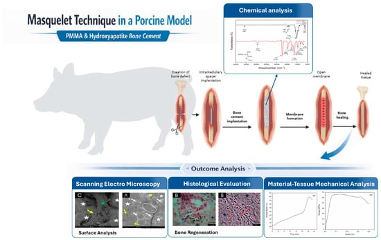
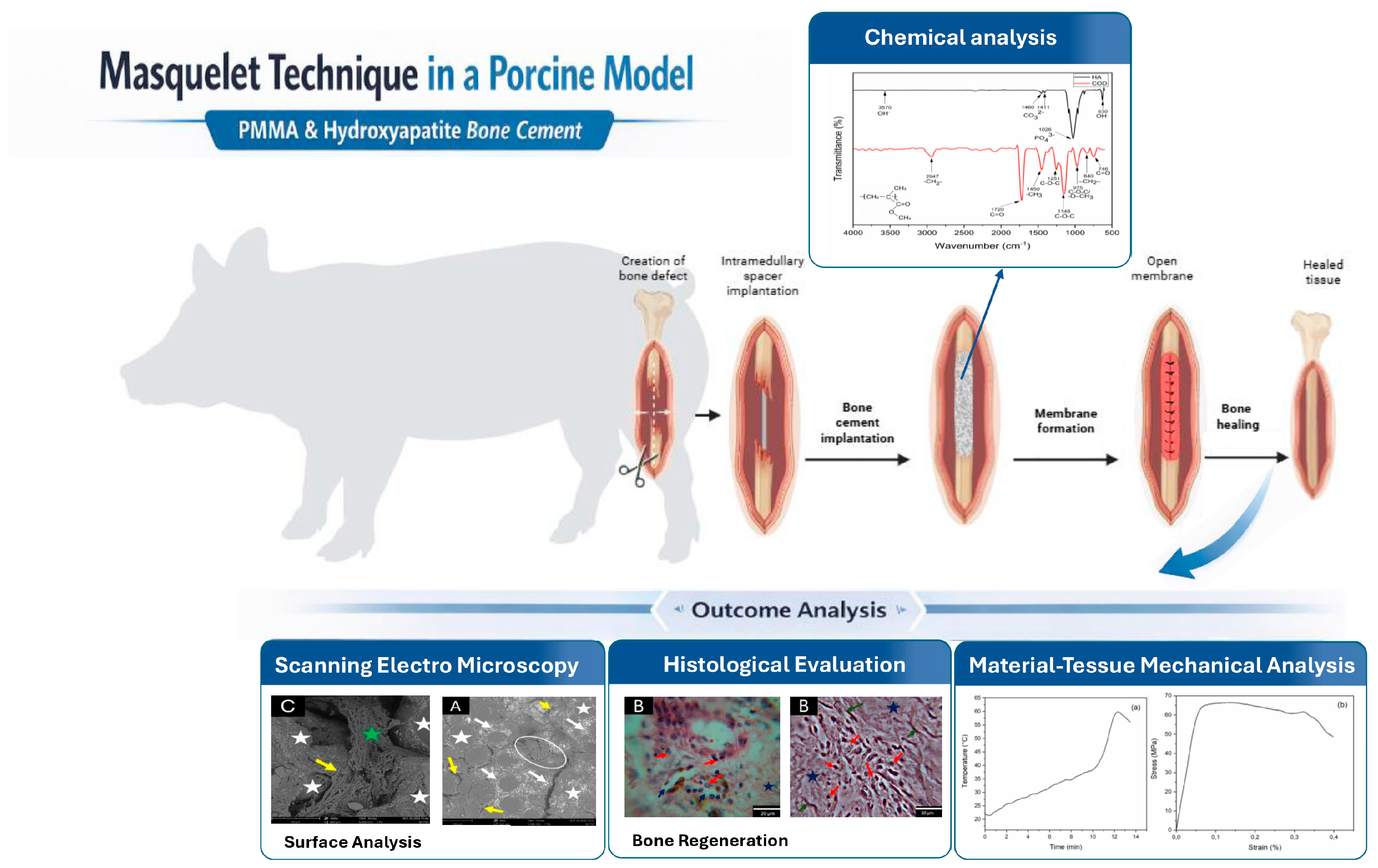
Graphical Abstract

1. Introduction

The reconstruction of critical bone defects remains a challenge in orthopedics and reconstructive surgery, particularly in cases of high-energy trauma, infection, or chronic osteomyelitis. These injuries require complex and multidisciplinary surgical management. In this context, the Masquelet-induced membrane technique has become established as an effective and reproducible strategy for treating extensive segmental bone defects, while other alternatives have limitations [1,2].
The Masquelet technique is performed in two stages: first, a temporary spacer, generally made of polymethyl methacrylate (PMMA), is implanted to induce the formation of a fibrovascular membrane. Subsequently, this membrane acts as a biological compartment that promotes revascularization and integration of the bone graft, processes that are fundamental for reconstructive success [3,4].
The induced membrane serves not only as a physical barrier but also as a biologically active tissue with characteristics similar to an induced periosteum. Previous studies have reported that the induced membrane exhibits fibrovascular and cellular characteristics associated with bone regeneration, supporting its key role in bone regeneration after the second surgical stage [5,6,7].
In recent years, scientific interest has shifted from the histological description of the induced membrane to the identification of the factors that determine its histological and structural characteristics. Experimental evidence indicates that variables such as maturation time, mechanical stability, and the physicochemical and structural characteristics of the spacer may influence its structural organization, vascularization, and histological features [8,9,10].
Although PMMA has traditionally been considered an inert material, studies have shown that modifications to its formulation or the use of alternative materials can yield membranes with distinct histological characteristics. Alternative polymeric spacers induce membranes with histological and cellular characteristics comparable to those induced by PMMA, suggesting that material–tissue interactions play a significant role [11,12].
Recent investigations have demonstrated that the immune response induced by the bone spacer (mainly PMMA-based cements and their variants) can influence the fibrovascular organization of the induced membrane. The activation and polarization of macrophages, along with other myeloid cells, have been associated with cytokine and growth factor expression in previous studies, suggesting that the membrane may represent a dynamic tissue environment associated with the biomaterial-induced response [13,14].
Despite existing evidence, few studies have comprehensively evaluated the effects of incorporating components with potential for biological interaction, such as hydroxyapatite and functional polymers, into bone cements on the biological response associated with the Masquelet technique, particularly in large-animal models. Most investigations have focused on small-animal models or isolated local evaluations, which limit understanding of material–tissue interactions under conditions more closely resembling the clinical setting [9,10].
This study aimed to analyze histological and structural differences in membranes induced by commercial and experimental bone cements using the Masquelet technique, and to describe their histological characteristics and material–tissue interaction. The hypothesis was proposed that differences in the formulation and microstructure of the cement could influence tissue organization and the distribution of vascular structures of the induced membrane.

2. Materials and Methods

2.1. Bone Cement Preparation

The bone cements evaluated included an experimental bone cement (COD) and a commercial bone cement (COC), which were analyzed for comparison. The experimental bone cement was formulated as a two-phase system comprising a solid phase (60 g) and a liquid phase (30 mL). The solid phase was composed of a polymeric matrix based on polymethyl methacrylate (PMMA) (Sigma-Aldrich, Mw ≈ 996,000 Da, St. Louis, MO, USA), incorporating bioactive and functional additives, including hydroxyapatite (HA) obtained from bovine femur, barium sulfate (BaSO4) (Alfa Aesar®, Johnson Matthey Company, Heysham, UK) as a radiopacifying agent, chitosan (CS) (Sigma-Aldrich, St. Louis, MO, USA), and polylactic acid (PLA) (Goodfellow Cambridge Ltd., Huntingdon, UK). Additionally, benzoyl peroxide (Alfa Aesar®, Johnson Matthey Company, Heysham, UK) was included as the polymerization initiator. The liquid phase consisted primarily of methyl methacrylate (MMA) (Merck, Darmstadt, Germany), used as the monomer, together with a comonomer system based on 2-(diethylamino)ethyl acrylate (Sigma-Aldrich, St. Louis, MO, USA) and 2-(dimethylamino)ethyl methacrylate (Merck, Darmstadt, Germany), as well as N,N-dimethyl-p-toluidine (DMPT) (Merck, Darmstadt, Germany), used as the accelerator of the redox system.
The hydroxyapatite used in this study was a natural apatite extracted from bovine femoral bone. It was processed after a surface silanization treatment with 3-aminopropyltriethoxysilane (APTES), following the procedure described by Lozano (2018) [15].
For comparative purposes, a commercial radiopaque antibiotic-loaded bone cement, Subiton GUN G (Laboratorios SL S.A., San Fernando, Argentina), supplied as a sterile two-component system (powder and liquid), was used. This cement belongs to the PMMA-based acrylic cement family and is preloaded with 1.25 wt% gentamicin, conferring broad-spectrum antibacterial activity.
The preparation of both cements was carried out by combining the powder and liquid phases in situ until a homogeneous, workable paste was obtained, before setting. Mixing was performed at room temperature (22 ± 2 °C) under controlled conditions, initially adding the liquid phase to the solid phase, then manually mixing with a sterile surgical spatula during the material’s plastic phase until a uniform, agglomerate-free consistency was achieved. Subsequently, the cement was manually applied directly into the bone defect.
Material hardening occurred in situ during the exothermic polymerization of MMA, catalyzed by the initiator–accelerator system present in each formulation. Complete curing of the cement was considered achieved once the characteristic mechanical rigidity of acrylic cement was reached, without the application of external heat sources or additional pressure.

2.2. In Vivo Studies

The implantation procedure was performed following the two-stage surgical protocol of the Masquelet technique [4,5].
In the first stage, a segmental femoral osteotomy was performed with resection of a controlled critical-sized bone defect of approximately 45 mm in length. The segment was previously stabilized with intramedullary fixation using a locked human humeral nail (7.0 mm × 200 mm), ensuring alignment and mechanical stability of the porcine biomodel before biomaterial implantation.
In the second surgical stage, the prepared bone cement was implanted into the previously stabilized segmental bone defect. Once a homogeneous mixture was obtained, the transition from the liquid phase to the plastic phase was identified by the appearance of fibrils upon contact with the surgical glove, a clinical criterion commonly used to determine the onset of the cement’s working phase [4,5]. At this moldable viscoelastic stage, the material was manually shaped and applied around the intramedullary nail, being uniformly distributed throughout the bone defect until reaching the proximal and distal margins of the exposed viable bone.
Subsequently, manual pressure was applied to ensure adequate adaptation and adherence of the cement to both the surface of the intramedullary implant and the walls of the bone defect, reproducing the morphology of the resected femoral segment and ensuring the formation of a stable spacer, in accordance with the surgical principles described for the Masquelet technique [4,10].

2.3. Chemical Characterization of Bone Cement by Fourier Transform Infrared Spectroscopy (FTIR)

The chemical characterization of the bone cements by Fourier transform infrared spectroscopy (FTIR) was performed using a Shimadzu IRAffinity-1S spectrometer, with a spectral resolution of 4 cm−1, in transmittance mode, over a wavenumber range of 4000 to 450 cm−1, using an attenuated total reflectance (ATR) accessory and performing 45 scans.

2.4. Determination of Thermal and Mechanical Properties

2.4.1. Thermal Properties

According to the protocols established in ISO 5833 (2002) [16], the thermal and handling properties of the acrylic bone cement paste were evaluated. In this regard, the cement was placed in a cylindrical Teflon mold (68 mm in diameter and 20 mm in height) to enable continuous temperature recording during polymerization. From the obtained temperature–time curve, the system’s maximum temperature ( T m a x ) was determined. Likewise, the setting time ( T s e t ) was defined as the time elapsed from the start of mixing to when the cement temperature reaches the setting temperature ( T s e t ), as calculated using Equation (1).
T s e t = T m a x + T a m b 2 ,
where T a m b is defined as the temperature recorded by the measuring device when the thermocouple is positioned within the mold at the beginning of the test. Four experimental replicates of the procedure were performed.

2.4.2. Mechanical Properties

The mechanical properties of bone cements were evaluated by compression testing in accordance with the guidelines of ISO 5833 (2002) [16]. Mechanical tests were performed using a Tinius Olsen H50KS universal testing machine (Tinius Olsen, Redhill, UK), equipped with a 10 KN load cell. Cylindrical specimens with dimensions of 6 mm in diameter and 12 mm in height were subjected to axial loading at a crosshead speed of 20 mm/min. For each material, at least five specimens were tested, and the reported values correspond to the mean ± standard deviation.

2.5. Animal Models and Surgical Procedure

Seven Creole pigs (Sus scrofa domesticus), approximately seven months old and with an average weight of 102.3 ± 14.1 kg, were initially included and maintained under controlled conditions.
Four animals were allocated to the experimental cement group (COD) and three to the commercial cement group (COC). However, one animal in the COC group required early euthanasia for humane reasons unrelated to the experimental protocol. Consequently, the final analysis was performed on six animals: four in the experimental group (COD) and two in the commercial group (COC).
Given the exploratory and qualitative nature of the study, no statistical comparisons were performed between groups.
Animals were allocated to the experimental groups using simple randomization by ballot (random draw) at the time of the surgical intervention. Due to the nature of the procedure and the preparation of different bone cements, blinding was not feasible at allocation or during surgical management, and the research team was aware of group assignments throughout the experimental phase.
All animals were monitored daily during the postoperative period to assess general condition, wound healing, and potential complications. At the predetermined endpoint of 45 days, animals were euthanized in accordance with established ethical protocols, and the induced membranes were harvested for histological and ultrastructural analyses.
The 45-day endpoint was selected to correspond to an early/intermediate stage of induced membrane maturation. Previous experimental and clinical studies have reported that important histological and biological characteristics of the membrane are particularly evident during the first 4–8 weeks after spacer implantation, a period commonly used for second-stage procedures in clinical practice [2,17,18]. Although some reports suggest that induced membranes may retain biological properties even several months after implantation, evidence from experimental and clinical studies indicates that this early interval represents a relevant phase for evaluating fibrovascular tissue organization and membrane maturation. Therefore, 45 days was considered appropriate for evaluating the histological and ultrastructural characteristics of the induced membrane [19,20,21].
Histological and scanning electron microscopy (SEM) evaluations were performed without formal blinding, and evaluators were aware of the experimental groups during image analysis and interpretation.
The animals were housed under continuous veterinary supervision, with ad libitum access to balanced feed and drinking water throughout the experimental period. The animals were selected for their anatomical and physiological similarities to humans, making them suitable for studying biomaterial–bone tissue interactions in preclinical regenerative medicine studies [22,23].
All procedures were carried out in accordance with national and international regulations on animal welfare and were approved by the Ethics Committee for Animal Use in Research (CEAS) of the Universidad del Valle, Cali, Colombia, under Resolution CEAS 006-020, ensuring compliance with the principles of replacement, reduction, and refinement (3Rs) for the ethical use of animals in research [24,25].
Each animal received a single implant of either commercial bone cement (COC) or experimental bone cement (COD), with stabilization of a 5 cm diaphyseal femoral defect using an intramedullary nail with proximal and distal locking, to simulate the first stage of the Masquelet technique and allow the formation of the induced membrane around the implanted material. The cement was placed in the previously created defect. After 45 days, considered sufficient for induced membrane maturation, the animals were euthanized to retrieve the bone segment and the formed membrane.
All surgical procedures were performed under general anesthesia and standardized aseptic conditions, in compliance with animal welfare regulations and ISO 10993-2:2022 [26], and in accordance with the principles of replacement, reduction, and refinement (3Rs).

2.6. Sample Retrieval and Histological Processing

After 45 days, the animals were subjected to humane euthanasia by intravenous injection of sodium pentobarbital (Euthanex®, Invent, Bogotá, Colombia). Tissue samples were fixed in 10% buffered formalin, dehydrated in graded alcohols (70, 80, 90, 96, and 100%), cleared in xylene, and embedded in paraffin.
Histological processing was performed using an Auto-Technicon Tissue Processor™ (Leica Microsystems, Mannheim, Germany) and a Thermo Scientific™ Shandon Histocentre 3 paraffin embedding station (Thermo Fisher Scientific, Waltham, MA, USA). The resulting paraffin blocks were sectioned at a thickness of 5 µm using a Leica Microsystems rotary microtome (Wetzlar, Germany).

2.7. Histological Staining and Microscopic Evaluation

The sections were stained with hematoxylin and eosin (H&E) for general evaluation of tissue architecture, and with Masson’s trichrome and Gomori staining for analysis of the fibrous stroma. Observations were performed using an optical microscope (Leica DM750, Leica Microsystems, Wetzlar, Germany)) coupled with a Leica DFC295 camera (Leica Microsystems, Wetzlar, Germany) and Leica Microsystems software (version 4.12.0, Leica Microsystems, Wetzlar, Germany).

2.8. SEM Sample Preparation and Ultrastructural Evaluation

Ultrastructural analysis was performed using scanning electron microscopy (SEM) with a Phenom Pro X (Thermo Fisher Scientific) equipped with a backscattered electron detector. The samples were previously dehydrated and sputter-coated, and analyses were carried out in spot mode using a standard sample holder and an accelerating voltage of 15 kV.

3. Results and Discussion

3.1. Fourier Transform Infrared Spectroscopy (FTIR) Analysis

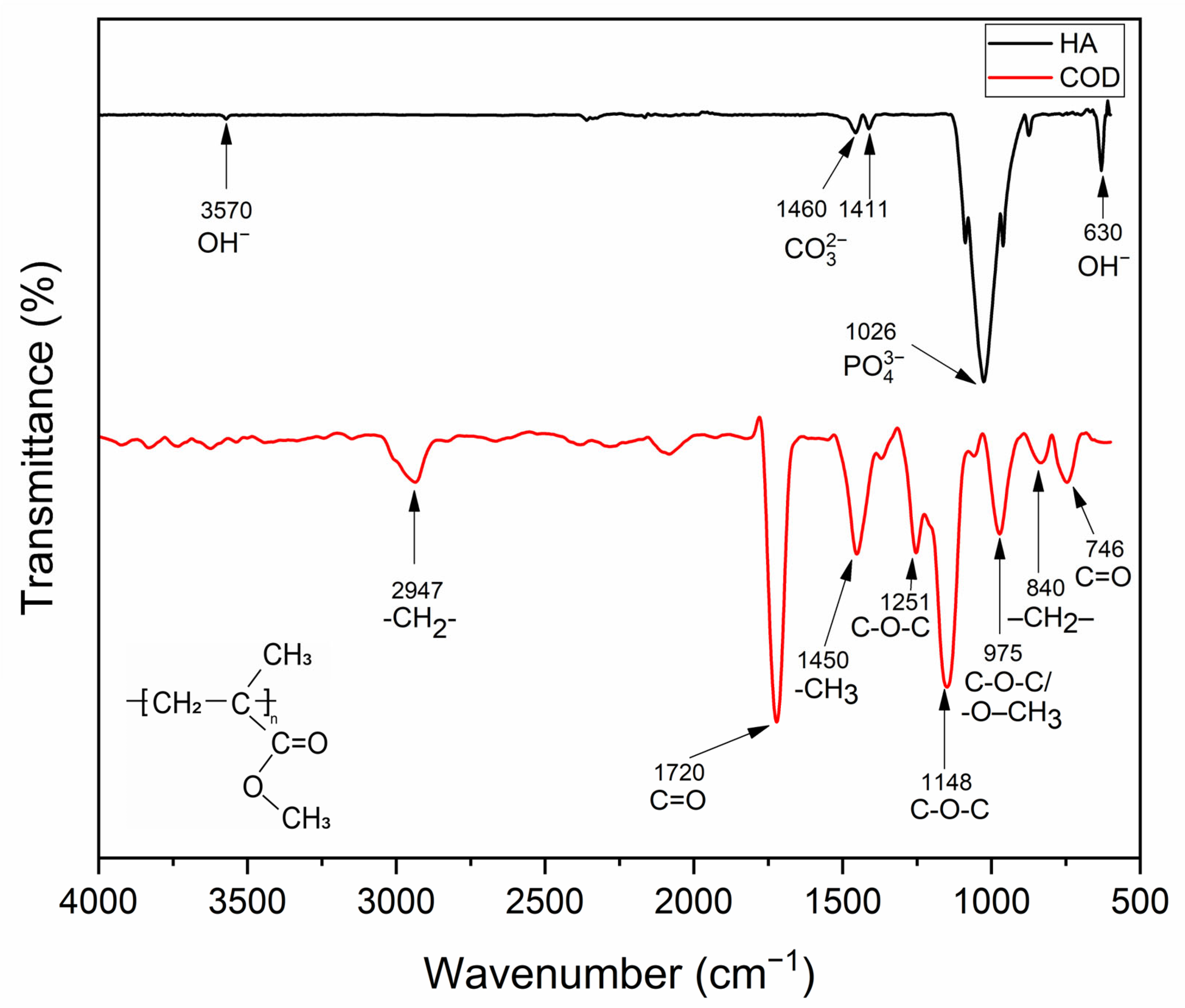
The FTIR spectrum of the analyzed bone cements (Figure 1) shows the characteristic bands of PMMA present in the experimental bone cement (COD), consistent with those reported in the literature for acrylic bone cements [27,28]. The band at 2947 cm−1 is associated with the asymmetric stretching ν_as(C–H) of methylene groups (–CH2–), while the intense signal observed around 1720 cm−1 corresponds to the stretching ν(C=O) of the ester group, which is considered a distinctive spectral fingerprint of PMMA. In the region of 1450–1435 cm−1, bending vibrations δ(CH3) and δ(CH2) are identified, in agreement with previous reports by Do Quang et al. (2021) and Chaurasiya and Ghosh (2023) [27,28].
Likewise, the bands in the range 1240–1148 cm−1 are attributed to ether bond stretching vibrations, ν(C–O–C), with a higher relative intensity observed near 1148 cm−1, a behavior also reported in modified PMMA cements and hydroxyapatite-containing formulations [29]. The signal detected at 975 cm−1 is related to a coupled vibrational mode between ν(C–O–C) stretching and ρ(CH3) rocking, while the peaks at 840 and 746 cm−1 are assigned to methylene rocking ρ(–CH2–) and out-of-plane bending modes of the carbonyl group, respectively. Overall, the agreement of these bands with those reported in the literature confirms the preservation of the chemical structure of PMMA and suggests that the incorporation of inorganic phases, such as hydroxyapatite (HA), does not induce the formation of new chemical bonds detectable by FTIR, but rather leads to physical interactions [28,29]. According to Chaurasiya and Ghosh (2023), the specific functional groups of PMMA remain unchanged upon addition of HA, indicating that incorporating the bioactive phase does not alter the chemical structure of the base polymer [28].
The FTIR spectroscopy of hydroxyapatite (HA) confirms the formation of the apatite phase through the presence of characteristic bands associated with phosphate groups (PO43−) and structural hydroxyl groups. In the spectrum, an intense band is observed around 1026 cm−1, attributed to the PO43 stretching modes, characteristic of the crystalline structure of hydroxyapatite. Likewise, a signal at 630 cm−1 is observed, corresponding to the vibration of the structural OH− group, which is distinctive of HA and allows it to be distinguished from other calcium phosphates. The coexistence of these bands provides clear evidence of the formation of a well-defined apatitic phase, consistent with reports in the literature for HA synthesized via various chemical and biogenic routes.
Additionally, a low-intensity band around 3570 cm−1 is detected, associated with the stretching of the structural OH− group in hydroxyapatite. The presence of this signal indicates the preservation of the characteristic hydroxyl channel of the apatitic structure. Furthermore, the bands observed at 1460 and 1411 cm−1 are attributed to vibrations of the CO32− group, suggesting partial carbonation of hydroxyapatite, a phenomenon commonly observed in HA synthesized under ambient conditions or after exposure to atmospheric CO2 [30,31,32].

3.2. Thermal and Mechanical Performance of Bone Cements According to ISO 5833

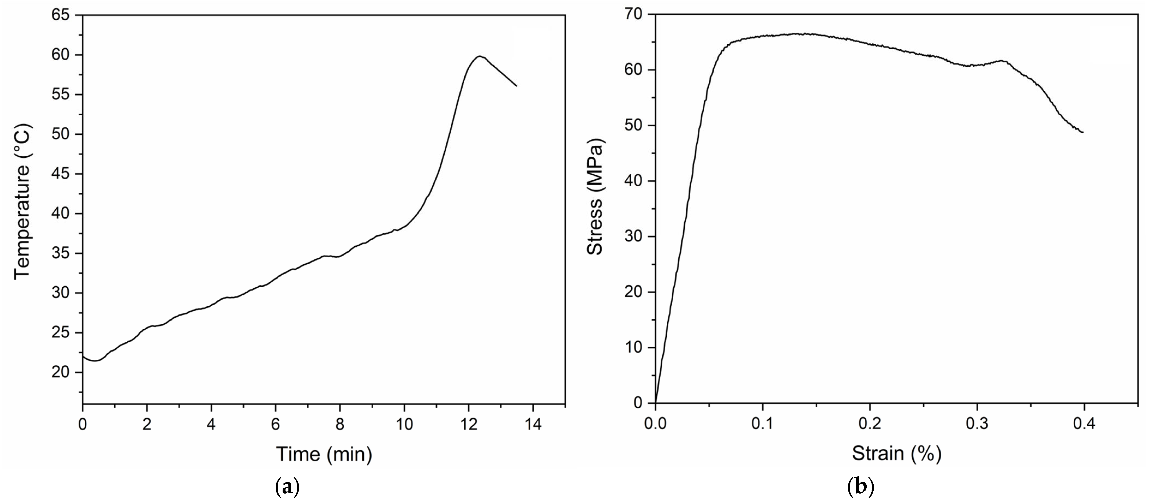
The thermal and mechanical performance of the experimental bone cement evaluated was analyzed in accordance with the criteria established in ISO 5833 (2002) [16], which defines acceptable limits for maximum polymerization temperature, setting time, and compressive strength for acrylic cements used in orthopedic applications. Representative curves from the tests are presented in Figure 2.
In terms of thermal behavior, the average maximum polymerization temperature (Tmax) for the tested cements was 61.50 ± 2.65 °C, while the average setting temperature was 41.88 ± 1.55 °C. The setting time was 9.68 ± 0.89 min, within the range specified by ISO 5833 (2002) [16], which establishes an acceptable setting time of 3–15 min and a maximum polymerization temperature below 90 °C. These results indicate that the polymerization process occurred in a controlled manner, reducing the risk of thermal damage to the surrounding tissue during clinical application (Table 1).
From a mechanical standpoint, the evaluated cement exhibited an average compressive strength of 68.93 ± 8.17 MPa, which is slightly below the minimum requirement established by ISO 5833 (≥70 MPa for conventional acrylic cements) [16]. Nevertheless, the obtained value remains close to the normative threshold and within the lower range reported for PMMA-based acrylic bone cements. Likewise, the compressive elastic modulus was 1.04 ± 0.15 GPa, consistent with ranges reported for PMMA-based acrylic bone cements (on the order of 1–3 GPa), including low-modulus formulations around 1.05 GPa, suggesting adequate load-bearing capacity under compression [33].
The thermal results fully comply with the requirements established by ISO 5833 (2002) [16], indicating a controlled polymerization process with a reduced risk of thermal damage to surrounding tissues. In contrast, the compressive mechanical performance was slightly below the standard-defined minimum threshold; however, the measured values remained close to the normative limit and within the range reported for PMMA-based bone cements. Overall, the evaluated material exhibits a favorable balance between thermal safety and mechanical performance for orthopedic applications. This balance is particularly relevant in the context of the Masquelet technique, where bone cement functions not only as a temporary spacer but also as a modulator of the biological microenvironment [4,10].

3.3. Histological Analysis of Induced Membranes

Overall, the induced membranes exhibited comparable topographical and architectural organization, characterized by the predominance of a dense collagenous matrix and preserved vascularization. However, variations in stromal organization, cellular density, and vascularization were observed among the samples, which may be associated with the type of bone cement used. Therefore, a representative image of the induced membrane associated with the experimental cement is first presented, followed by an analysis of individual samples.
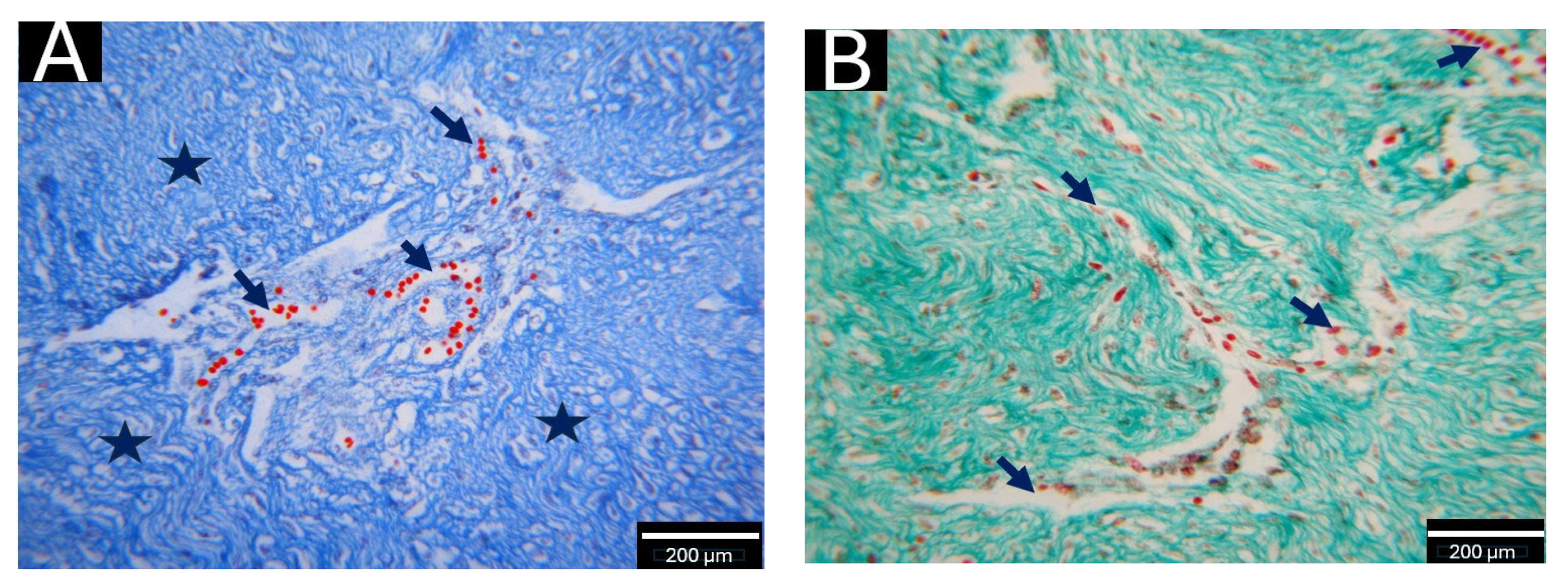
Figure 3 shows an induced membrane following implantation of the experimental cement. In Figure 3A (Masson’s trichrome), dense and irregular connective tissue is observed, with abundant collagen bundles and small-caliber blood vessels, showing the presence of small-caliber vascular structures. The presence of vascular structures has been described as part of the membrane’s tissue organization induced during the intermediate stages of maturation in the Masquelet technique [5,19]. In Figure 3B (Gomori staining), a dense and irregular collagenous matrix is evident, with reticular fibers compatible with type III collagen, and no signs of necrosis or hemorrhage, suggesting a membrane in an advanced intermediate stage of maturation [5,7].
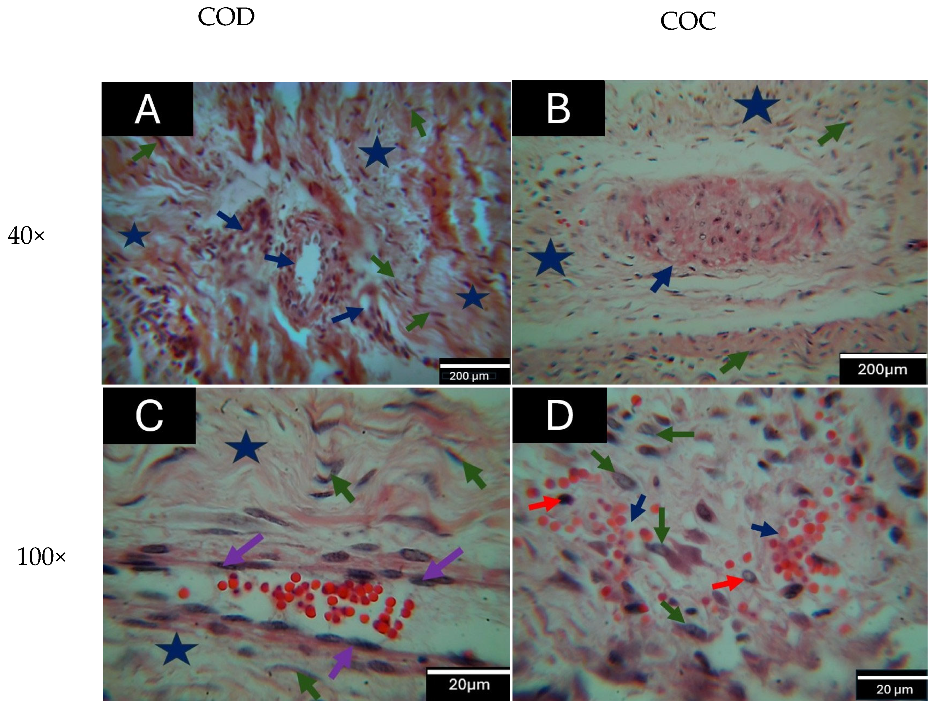
To evaluate the overall tissue organization of the induced membranes, histological analysis was performed using hematoxylin and eosin (H&E) staining. To facilitate comparative interpretation between the groups, the histological images were reorganized and presented together at equivalent magnifications, allowing for a direct visual assessment of tissue organization, vascularization, and cellularity of the induced membranes. These findings are presented in Figure 4.
At low magnification (40×), both experimental conditions (COD and COC) exhibit a fibrovascular architecture characterized by a dense, irregularly arranged collagenous stroma and vascular structures distributed throughout the tissue.
At higher magnification (100×), characteristics of the tissue microstructure are evident, including the arrangement of the stroma, the presence of erythrocytes associated with vascular structures, and the identification of cells consistent with fibroblasts and mononuclear inflammatory infiltrate. Vascular structures with permeable lumens and intraluminal erythrocytes were also identified, surrounded by fibrocollagenous stroma with spindle cells consistent with fibroblasts and a mild, predominantly perivascular, mononuclear inflammatory infiltrate, without evidence of necrosis or significant tissue damage. These characteristics showed variability among the analyzed samples, although no quantitative differences between the groups were established at this stage.
Taken together, these observations constitute a qualitative analysis of the induced membranes and enable a general comparison among the evaluated conditions, in accordance with the study’s descriptive approach.
Vascular structures with a permeable lumen and characteristics consistent with a preserved endothelium were also identified, containing intraluminal erythrocytes, surrounded by fibrocollagenous stroma with spindle cells consistent with fibroblasts, and a mild, predominantly perivascular mononuclear inflammatory infiltrate, without evidence of necrosis or significant tissue damage.
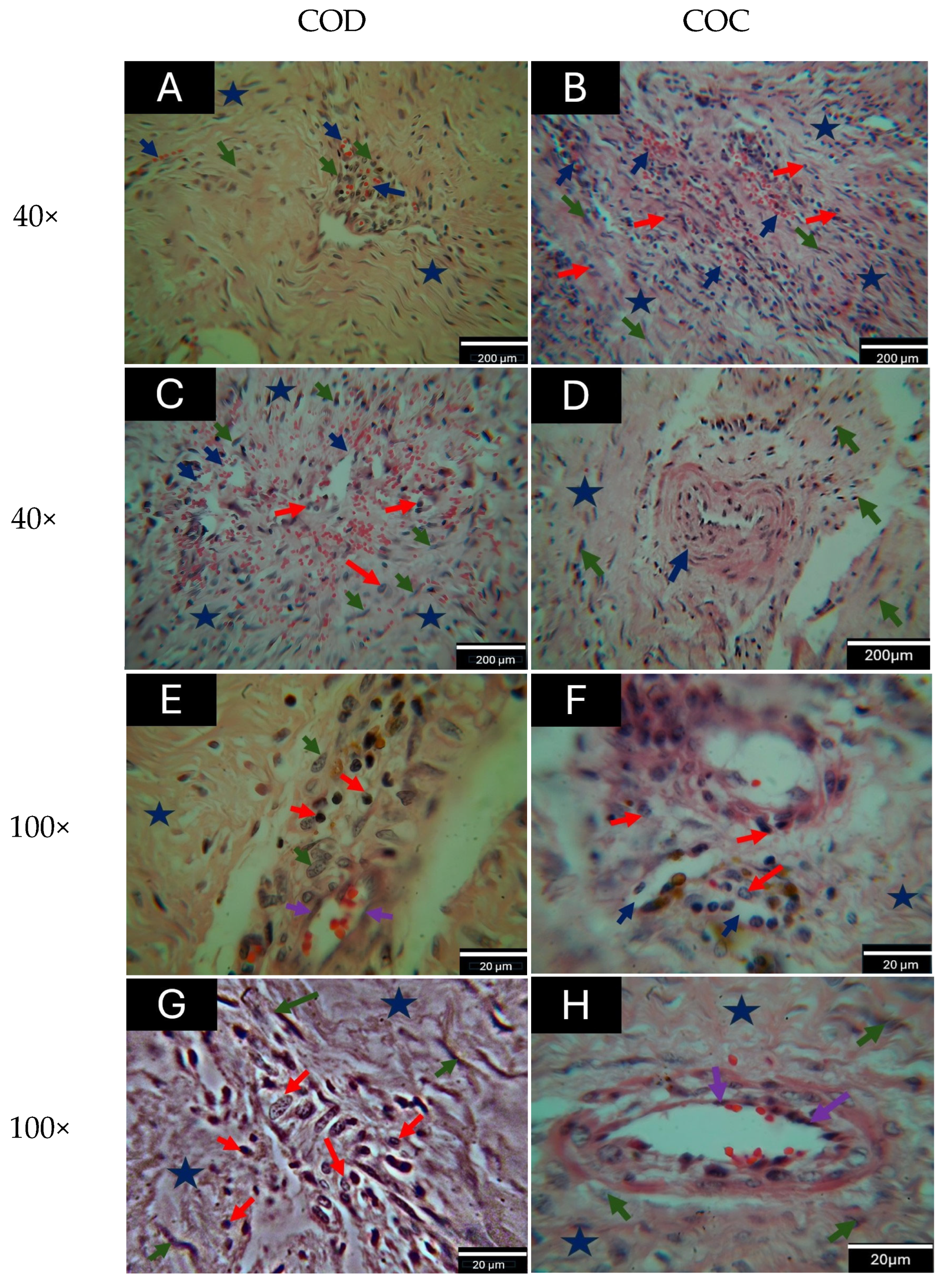
Additionally, other representative samples of the induced membranes were evaluated, and their histological findings are presented in Figure 5.
As shown in Figure 5, the additional histological images at low (40×) and high (100×) magnification illustrate the qualitative variability observed across different regions and samples of the induced membranes from both experimental groups.
At higher magnification (100×), morphological variations in stromal organization and cell distribution are observed among the different samples analyzed. Taken together, these observations reflect the morphological variability among samples and regions within each experimental group, consistent with the study’s qualitative approach. These characteristics are consistent with those described for intermediate stages of induced membrane maturation in the Masquelet technique [5].
The coexistence of vascular structures, fibrocollagenous stroma, and a mild mononuclear inflammatory infiltrate is consistent with the histological patterns described in membranes induced during intermediate stages of tissue organization [21,34].
Taken together, the qualitative observations indicate variability in stromal organization, cell distribution, and vascular structure across samples and regions of the same membrane, reflecting the heterogeneity in tissue organization previously described for this type of structure [7].
From a histological perspective, the induced membrane can be considered an organized structure that serves as a physical barrier and a tissue-interaction environment during the initial stages of bone defect repair [23,34]. Furthermore, the presence of perivascular zones and spindle cells is consistent with previously described patterns of tissue organization in induced membranes [19].
Although both experimental conditions (COD and COC) exhibited comparable fibrovascular architecture, qualitative variations were observed in stromal fibrillar organization, cell distribution, and tissue organization. These findings are consistent with reports suggesting that the physicochemical and microstructural characteristics of the spacer may be associated with differences in material–tissue interaction and in the histological characteristics of the induced membrane [20].
Overall, the results suggest that the induced membrane constitutes a complex tissue sensitive to the characteristics of the implanted biomaterial, in which the tissue organization and the distribution of vascular structures reflect patterns of interaction between the material and the tissue environment generated during the first stage of the Masquelet technique.

3.4. Ultrastructural Analysis by Scanning Electron Microscopy (SEM)

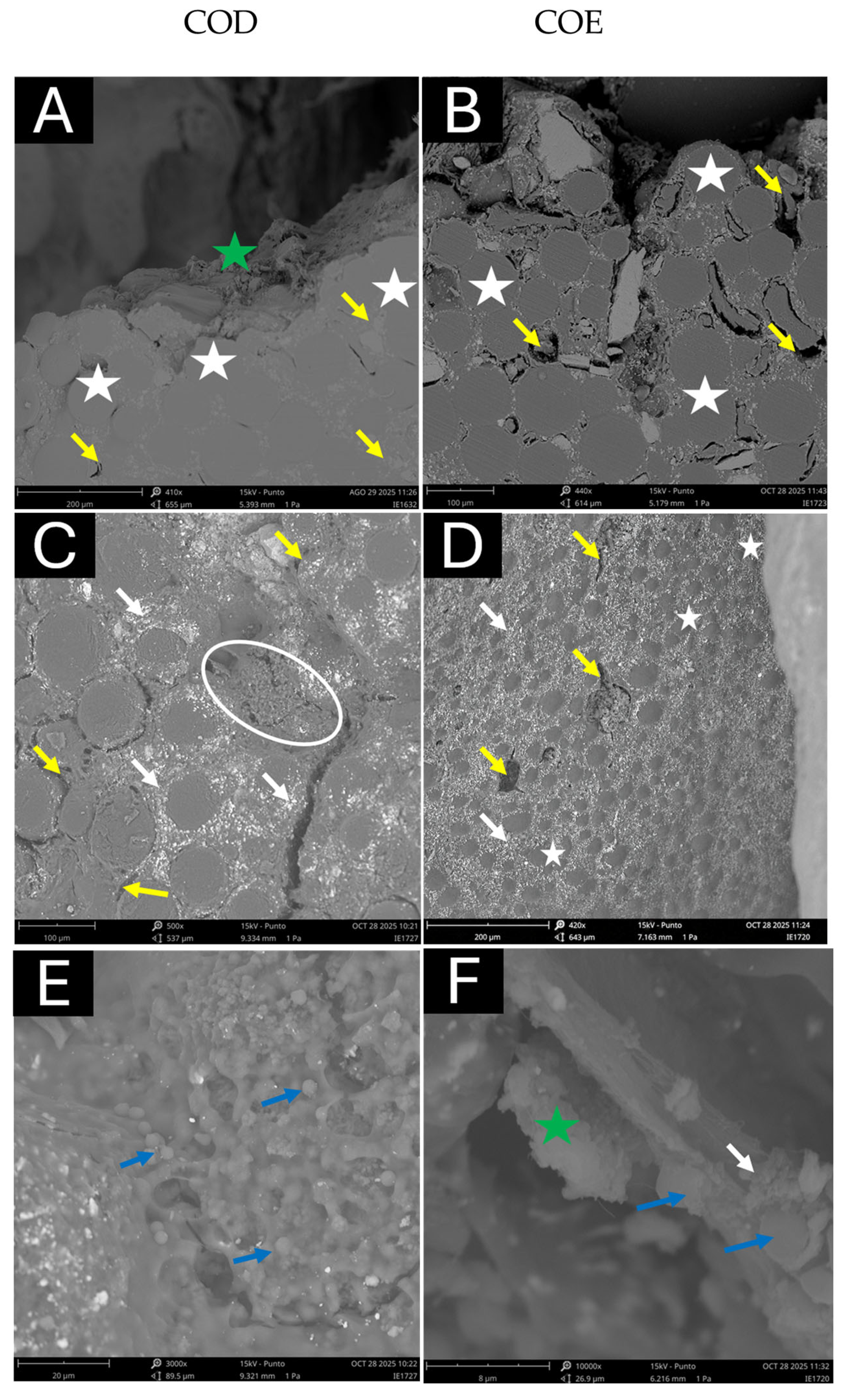
To evaluate the material–tissue interaction at the ultrastructural level, scanning electron microscopy (SEM) analysis was performed on representative samples of the experimental (COD) and commercial (COC) bone cements. To facilitate comparative interpretation between the two groups, the micrographs were reorganized and presented together, grouped by magnification and type of structure observed, thereby allowing a morphological assessment of the material’s surface architecture, interfacial regions, and the microstructural characteristics of the deposits.
As shown in Figure 6, at low magnification (400–450×; Figure 6A,B), both conditions exhibit a characteristic arrangement of PMMA beads delimited by interbead spaces and irregular surface cavities. At this level, material deposits with varying degrees of distribution are observed on the cement surface and in the spaces between the beads.
At intermediate magnifications (420–500×; Figure 6C,D), regions with accumulations of granular material adhering to the cement surface are identified, as well as areas with more continuous surface-associated deposits, demonstrating variability in the morphology and distribution of the deposits.
Finally, at higher magnifications (6000–10,000×; Figure 6E,F), structures with fibrillar and granular morphology are evident, as well as spherical or rounded elements distributed on the surface of the material and in cavities.
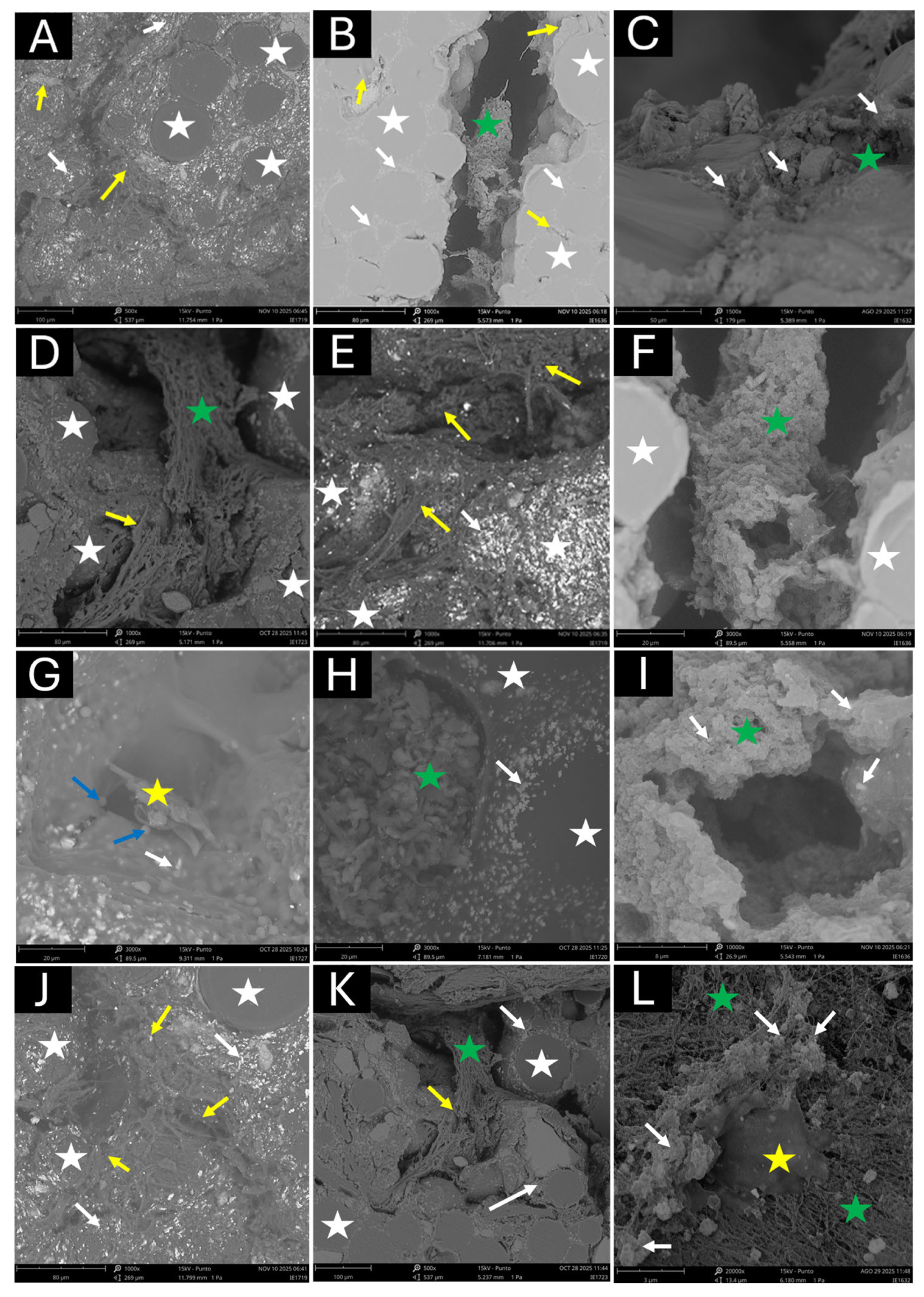
The observations are consistent with a morphological analysis, and conventional SEM cannot confirm the nature of the observed structures. To demonstrate the morphological variability observed across the analyzed regions, additional SEM micrographs are presented for the experimental (COD) and commercial (COC) bone cements (Figure 7).
These images, acquired at different magnification levels, complement the evaluation of material–tissue interaction by showing alternative patterns of surface organization, deposit distribution, and microstructural characteristics that are not fully apparent in Figure 6. As shown in Figure 7, at low and medium magnification (Figure 7A–F), variations are observed in the arrangement of the PMMA beads and in the morphology of the interbead spaces, as well as in different patterns of material accumulation on the cement surface. In some regions, deposits exhibit a heterogeneous distribution, while in others, a more continuous coating is observed, suggesting differences in the distribution of surface-associated deposits at the interface.
At higher magnifications (Figure 7G–L), granular deposits and structures with a fibrillar morphology are seen in greater detail, as well as spherical or rounded elements distributed on the surface of the material and in cavities. These observations reflect the morphological variability at the material–tissue interface and among the different regions analyzed.
The observations are consistent with a morphological analysis, and conventional SEM cannot confirm the nature of the observed structures.
To facilitate the comparative interpretation of the histological and ultrastructural findings between the groups, a summary of the main observations is presented in Table 2.
Although both experimental groups (COD and COC) exhibited comparable fibrovascular architecture, qualitative variations were observed in stromal organization, cell distribution, and material–tissue interaction patterns among the induced membranes associated with each cement [20].
Taken together, these findings suggest that the characteristics of the implanted biomaterial may be associated with qualitative differences in the membrane’s tissue organization induced during the first stage of the Masquelet technique.
From an ultrastructural perspective, SEM observations showed that the material–tissue interaction is not uniform but varies with the material’s microstructure and the analyzed region. Deposits with amorphous, granular, and fibrillar morphology were identified both on the cement surface and within the interbead spaces. These spaces could act as regions of material accumulation and tissue interaction.
Furthermore, differences were observed in the distribution of these deposits across the materials. In the experimental cement, deposition exhibited qualitatively distinct distribution patterns, whereas in the commercial cement, it appeared more localized and associated with surface irregularities. These observations suggest that the material’s characteristics may be associated with differences in tissue organization at the interface. However, since SEM provides only morphological information, any biological interpretation remains indirect.
The literature indicates that the induced membrane response is closely related to the tissue response induced by the biomaterial, which depends on the characteristics of the implanted material [13]. In this context, the observed ultrastructural differences could be associated with variations in this response.
Similarly, the induced membrane has been described as an organized tissue structure present at the defect site [35]. The presence of fibrillar structures and amorphous material observed at higher magnification is compatible with fibrillar and amorphous tissue-associated structures.
Vascularization has been described as an important component in the organization of the induced membrane. Although this aspect was not directly evaluated, the observed morphological differences could be related to variations in tissue–material interaction [14].
Finally, there is evidence that the spacer material may influence the characteristics of the induced membrane. Different compositions may alter tissue organization and material–tissue interaction patterns [9], [10]. In this regard, the findings of the present study suggest that the observed ultrastructural differences could be associated with variations in tissue organization at the interface.

4. Conclusions

In this study, histological and ultrastructural analyses of induced membranes generated with the Masquelet technique demonstrated that the material–tissue interface exhibited qualitative patterns of tissue organization that the bone cement’s characteristics may influence.
Overall, membranes associated with experimental cement showed qualitative differences in stromal organization, cell distribution, and vascular structure distribution compared to those observed with the commercial cement. At the ultrastructural level, scanning electron microscopy analysis suggested a more homogeneous material–tissue interaction in the experimental cement, with continuous amorphous and fibrillar material present both on the surface and within inter-bead spaces. In contrast, in commercial cement, this interaction was more localized.
Taken together, these findings suggest that the formulation and microstructure of bone cement may influence qualitative patterns of tissue organization and material–tissue interaction during the first stage of the Masquelet technique. However, these results should be interpreted with caution, as they are primarily based on qualitative observations and are limited by a small sample size and the absence of molecular or compositional characterization of the observed deposits. In this regard, future studies incorporating molecular, immunohistochemical, or SEM-EDS analyses could provide more conclusive information regarding the nature of these interactions.

Author Contributions

Conceptualization, J.L.C.-G., J.A.L.-P., J.C.M.-P., G.U.-G., C.H.V.-L., C.D.G.-T., N.A.A.-P. and M.F.M.-V.; Methodology, J.P.R.-O., L.F.P.-M., N.A.A.-P. and C.H.V.-L.; Project Administration, C.H.V.-L., J.H.M.-H. and C.D.G.-T.; Supervision, C.H.V.-L. and J.H.M.-H.; Investigation, J.P.R.-O., L.F.P.-M., N.A.A.-P. and A.J.A.; Writing—Original Draft, C.H.V.-L., J.P.R.-O., M.F.M.-V., N.A.A.-P., C.D.G.-T. and J.H.M.-H.; Writing—Review & Editing, J.L.C.-G., J.A.L.-P., J.C.M.-P., G.U.-G., M.F.M.-V., C.H.V.-L., C.D.G.-T., N.A.A.-P. and M.F.M.-V. All authors have read and agreed to the published version of the manuscript.

Funding

This work was funded by MinCiencias, Colombia, under Contract No. 2022-0474 (Project No. 82175 “Pruebas de uso a un Cemento Óseo Experimental”).

Institutional Review Board Statement

All procedures were carried out in accordance with national and international regulations on animal welfare and were approved by the Ethics Committee for Animal Use in Research (CEAS) of Universidad del Valle, Cali, Colombia, under Resolution CEAS 006-020 (initial approval issued on 11 November 2020, with subsequent renewals approved on 21 September 2023 and 10 October 2024).

Informed Consent Statement

Not applicable, as the study did not involve human participants.

Data Availability Statement

The original contributions presented in this study are included in the article. Further inquiries can be directed to the corresponding authors.

Acknowledgments

The authors gratefully acknowledge the Ministerio de Ciencia, Tecnología e Innovación (MinCiencias), Universidad del Valle, Universidad del Atlántico, and ValleSalud-IPS for their financial and institutional support in the development of this project.

Conflicts of Interest

The authors declare no conflicts of interest.

Abbreviations

The following abbreviations are used in this manuscript:
HAHydroxyapatite
H&EHematoxylin and Eosin
PMMAPolymethyl methacrylate
SEMScanning electron microscopy

References

  1. Pederiva, D.; De Luca, L.; Faldini, C.; Vergano, L.B. Masquelet’s Induced Membrane Technique in the Upper Limb: A Systematic Review of the Current Outcomes. J. Orthop. Traumatol. 2025, 26, 4. [Google Scholar] [CrossRef] [Scilit]
  2. Sun, S.; Tsai, W.; Shiu, S.; Chen, C. Induced Membrane Technique for Large Bone Defects. Medicine 2022, 101, e29292. [Google Scholar] [CrossRef] [Scilit] [PubMed]
  3. Cho, J.; Kent, W.T.; Oh, C.; Kim, B.; Cho, W.; Oh, J. Bone-Graft Resorption Reduced by the Induced Membrane Technique and Factors Affecting Volumetric Changes. J. Bone Jt. Surg. 2020, 102, 1269–1278. [Google Scholar] [CrossRef] [Scilit]
  4. Klein, C.; Monet, M.; Barbier, V.; Vanlaeys, A.; Gouron, A.M.R.; Mentaverri, R. The Masquelet Technique: Current Concepts, Animal Models, and Perspectives. J. Tissue Eng. Regen. Med. 2020, 14, 1349–1359. [Google Scholar] [CrossRef] [Scilit]
  5. Littlefield, C.P.; Wang, C. The Basic Science Behind the Clinical Success of the Induced Membrane Technique for Critical-Sized Bone Defects. J. Bone Jt. Surg. 2021, 9, e20. [Google Scholar] [CrossRef] [Scilit] [PubMed]
  6. Bowman, M.; Sclamberg, G.; Wessels, E.; Cragg, K.; Donneys, A.; Hake, M.E.; Alford, A.I. Paracrine Influence of Masquelet’s Induced Membrane on Marrow Derived Mesenchymal Stem Cells. J. Orthop. Res. 2025, 43, 922–930. [Google Scholar] [CrossRef] [Scilit]
  7. Wang, K.; Gao, F.; Zhang, Y.; Dai, B.; Yan, X.; He, X.; Mao, D.; Rui, Y. Comparison of Osteogenic Activity from Different Parts of Induced Membrane in the Masquelet Technique. Injury 2023, 54, 111022. [Google Scholar] [CrossRef] [Scilit]
  8. Xie, J.; Liu, D.; Wang, H.; Long, H.; Zhu, Y.; Hu, Y.; Zeng, M. Effects of Topical Mechanical Stability on the Formation of Masquelet Membrane in a Rabbit Radial Defect Model. Sci. Rep. 2020, 10, 18939. [Google Scholar] [CrossRef] [Scilit]
  9. Toth, Z.; Roi, M.; Evans, E.; Watson, J.T.; Nicolaou, D.; McBride-Gagyi, S. Masquelet Technique: Effects of Spacer Material and Micro-Topography on Factor Expression and Bone Regeneration. Ann. Biomed. Eng. 2019, 47, 174–189. [Google Scholar] [CrossRef] [Scilit] [PubMed]
  10. Liodakis, E.; Giannoudis, V.P.; Sehmisch, S.; Jha, A.; Giannoudis, P. V Bone Defect Treatment: Does the Type and Properties of the Spacer Affect the Induction of Masquelet Membrane ? Evidence Today. Eur. J. Trauma Emerg. Surg. 2022, 48, 4403–4424. [Google Scholar] [CrossRef] [Scilit]
  11. Mathieu, L.; Murison, J.C.; De Rousiers, A.; De Escalopier, N.; Lutomski, D.; Collombet, J.; Durand, M. The Masquelet Technique: Can Disposable Polypropylene Syringes Be an Alternative to Standard PMMA Spacers? A Rat Bone Defect Model. Clin. Orthop. Relat. Res. 2021, 479, 2737–2751. [Google Scholar] [CrossRef] [Scilit] [PubMed]
  12. Junior, L.D.C.; Rahal, S.C.; Souza, M.A.; Osowski, A.; Júnior, J.I.S.S. Induced Membrane Technique Using Bone Cement with or without Cefazolin in Chicken Segmental Radius Defect. Front. Vet. Sci. 2023, 10, 1027951. [Google Scholar] [CrossRef] [Scilit]
  13. Durand, M.; Oger, M.; Nikovics, K.; Venant, J.; Guillope, A.; Barbier, L.; Laurent, B.; Poirier, F.; Rousseau, C.; Pitois, O.; et al. Influence of the Immune Microenvironment Provided by Implanted Biomaterials on the Biological Properties of Masquelet-Induced Membranes in Rats: Metakaolin as an Alternative Spacer. Biomedicines 2022, 10, 3017. [Google Scholar] [CrossRef] [Scilit] [PubMed]
  14. Wang, W.; Zuo, R.; Long, H.; Wang, Y.; Zhang, Y.; Sun, C.; Luo, G.; Zhang, Y.; Li, C.; Zhou, Y.; et al. Advances in the Masquelet Technique: Myeloid-Derived Suppressor Cells Promote Angiogenesis in PMMA-Induced Membranes. Acta Biomater. 2020, 108, 223–236. [Google Scholar] [CrossRef] [Scilit] [PubMed]
  15. Lozano, K.-J. Preparación y Caracterización de Cementos Óseos Acrílicos Modificados Para Su Aplicación En La Fijación de Material de Osteosíntesis. Master’s Thesis, Universidad del Valle, Cali, Colombia, 2020. [Google Scholar]
  16. ISO 5833:2002; Implants for Surgery—Acrylic Resin Cements. International Organization for Standardization: Geneva, Switzerland, 2002.
  17. Musa, R.A.; Shah, D.U.; Makwana, V.R.; Hadiya, A.K.; Shah, P.K.; Bhavsar, N.M. Masquelet’s Induced Membrane Technique for the Reconstruction of Post-Traumatic, Open-Grade Distal Femur Fracture with Bone Defect. J. Orthop. Trauma Rehabil. 2021, 29, 1–7. [Google Scholar] [CrossRef] [Scilit]
  18. Ahmed, H.; Ahmed, H. A Review of the Masquelet Technique in the Treatment of Lower Limb Critical-Size Bone Defects. Ann. R. Coll. Surg. Engl. 2025, 107, 383–389. [Google Scholar] [CrossRef] [Scilit]
  19. Gindraux, F.; Loisel, F.; Bourgeois, M.; Oudina, K.; Melin, M.; De Billy, B.; Sergent, P.; Leclerc, G.; Petite, H.; Auber, F.; et al. Induced Membrane Maintains Its Osteogenic Properties Even When the Second Stage of Masquelet ’ s Technique Is Performed Later. Eur. J. Trauma Emerg. Surg. 2020, 46, 301–312. [Google Scholar] [CrossRef] [Scilit]
  20. Wu, J.; Bao, Q.; Wang, S.; Zhou, P.; Xu, S. Mechanisms of the Masquelet Technique to Promote Bone Defect Repair and Its Influencing Factors. Chin. J. Traumatol. 2025, 28, 157–163. [Google Scholar] [CrossRef] [Scilit]
  21. Aho, O.; Lehenkari, P.; Ristiniemi, J.; Lehtonen, S.; Risteli, J. The Mechanism of Action of Induced Membranes in Bone Repair. J. Bone Jt. Surg. Am. 2013, 95, 597–604. [Google Scholar] [CrossRef] [Scilit]
  22. Pearce, A.; Richards, R.; Milz, S.; Schneider, E.; Pearce, S. Animal Models for Implant Biomaterial Research in Bone: A Review. Eur. Cells Mater. 2007, 13, 1–10. [Google Scholar] [CrossRef] [Scilit]
  23. Ribitsch, I.; Baptista, P.M.; Lange-consiglio, A.; Melotti, L.; Patruno, M.; Jenner, F.; Schnabl-feichter, E.; Dutton, L.C.; Connolly, D.J.; Van Steenbeek, F.G.; et al. Large Animal Models in Regenerative Medicine and Tissue Engineering: To Do or Not to Do. Front. Bioeng. Biotechnol. 2020, 8, 972. [Google Scholar] [CrossRef] [Scilit] [PubMed]
  24. Hubrecht, R.C.; Carter, E. The 3Rs and Humane Experimental Technique: Implementing Change. Animals 2019, 9, 754. [Google Scholar] [CrossRef] [Scilit]
  25. Du Sert, N.P.; Hurst, V.; Ahluwalia, A.; Alam, S.; Avey, M.T.; Baker, M.; Browne, W.J.; Clark, A.; Cuthill, I.C.; Dirnagl, U.; et al. The Arrive Guidelines 2.0: Updated Guidelines for Reporting Animal Research. PLoS Biol. 2020, 18, e3000410. [Google Scholar] [CrossRef] [Scilit]
  26. ISO 10993-2:2022; Biological Evaluation of Medical Devices—Part 2: Animal Welfare Requirements. International Organization for Standardization: Geneva, Switzerland, 2022.
  27. Do Quang, T.; Linh, N.T.D.; Van, D.T.C.; Cong, D.V.; Dung, N.T.K.; Trang, N.T.T.; Lam, P.V.; Hoang, T.; Lam, T. PMMA Bone Cements Modified with Silane-Treated and PMMA-Grafted Hydroxyapatite Nanocrystals: Preparation and Characterization. Polymers 2021, 13, 3860. [Google Scholar]
  28. Chaurasiya, S.P.; Ghosh, R. Forces in Mechanics Low Viscosity versus High Viscosity PMMA Bone Cement for Total Joint Arthroplasty: Influence of Glass Transition Temperature, Residual Monomer Content, Transmittance of Chemical Functional Groups, and Crystallinity Index on Quasi-Static Flexural Strength. Forces Mech. 2023, 10, 100176. [Google Scholar] [CrossRef] [Scilit]
  29. Valencia Zapata, M.E.; Mina Hernandez, J.H.; Grande Tovar, C.D. Acrylic Bone Cement Incorporated with Low Chitosan Loadinngs. Polymers 2020, 12, 1617. [Google Scholar] [CrossRef] [Scilit]
  30. Abdelmoaty, A.; Mousa, S. Synthesis and Characterization of Hydroxyapatite Nanoparticles from Calcium Hydroxide Fouled with Gases Evolved from Smokestack of Glass Industry. Sci. Rep. 2024, 14, 10969. [Google Scholar] [CrossRef] [Scilit]
  31. Dumitrescu, C.R.; Neacsu, I.A.; Surdu, V.A.; Nicoara, A.I.; Iordache, F.; Trusca, R.; Ciocan, L.T.; Ficai, A.; Andronescu, E. Nano-Hydroxyapatite vs. Xenografts: Synthesis, Characterization, and in Vitro Behavior. Nanomaterials 2021, 11, 2289. [Google Scholar] [CrossRef] [Scilit]
  32. Kang, S.; Haider, A.; Gupta, K.C.; Kim, H. Chemical Bonding of Biomolecules to the Surface of Nano-Hydroxyapatite to Enhance Its Bioactivity. Coatings 2022, 12, 999. [Google Scholar] [CrossRef] [Scilit]
  33. Lardilleux, C.; Lavergne, C.; Marcq, F.; Faruch, M.; Lacabanne, C.; Dantras, E. Long-Term Performance of a Low-Modulus Acrylic Cement in a Simulated Physiological Environment. Med. Eng. Phys. 2025, 145, 104447. [Google Scholar] [CrossRef] [Scilit]
  34. Niikura, T.; Jimbo, N.; Komatsu, M.; Oe, K.; Fukui, T.; Matsumoto, T.; Hayashi, S.; Matsushita, T.; Sakai, Y.; Itoh, T.; et al. Histological Analysis of Induced Membranes in Patients Whose Bone Defects Were Treated with the Masquelet Technique to Identify Factors Affecting the Vascularity of Induced Membranes. J. Orthop. Surg. Res. 2021, 7, 248. [Google Scholar] [CrossRef] [Scilit]
  35. Debaun, M.R.; Yang, Y.P.; Stahl, A.M.; Daoud, A.I.; Pan, C.; Bishop, J.A.; Gardner, M.J. Preclinical Induced Membrane Model to Evaluate Synthetic Implants for Healing Critical Bone Defects Without Autograft. J. Orthop. Res. 2018, 37, 60–68. [Google Scholar] [CrossRef] [Scilit]
Figure 1. FTIR spectra of experimental bone cement (COD) and hydroxyapatite (HA).
Sci 08 00121 g001
Figure 2. COD cement curves: (a) determination of setting time and maximum polymerization temperature (temperature–time curve); (b) compressive stress–strain curve.
Sci 08 00121 g002
Figure 3. Induced membrane associated with the experimental bone cement (COD). (A) Masson’s trichrome staining (10×), where collagen fibers appear blue. (B) Gomori staining (10×). Blue asterisks: dense, irregular collagen. Blue arrows: blood vessels, where collagen fibers appear green.
Sci 08 00121 g003
Figure 4. Histological comparison of induced membranes associated with experimental (COD) and commercial (COC) bone cements (H&E stain). Images are organized by experimental group (columns) and magnification (rows) to facilitate direct comparison. (A) COD, 40×; (B) COC, 40×; (C) COD, 100×; (D) COC, 100×. Blue stars: Dense irregular collagen. Blue arrows: Blood vessels or erythrocytes. Green arrows: Cells consistent with fibroblasts. Red arrows: Inflammatory cells. Purple arrows: Cells consistent with endothelial cells.
Sci 08 00121 g004
Figure 5. Histological variability of induced membranes associated with experimental (COD) and commercial (COC) bone cements (H&E stain). Images are organized by experimental group (columns) and magnification (rows) to facilitate direct comparison. (A,C) COD, 40×; (B,D) COC, 40×; (E,G) COD, 100×; (F,H) COC, 100×. Blue stars: Dense irregular collagen. Blue arrows: Blood vessels or erythrocytes. Green arrows: Cells consistent with fibroblasts. Red arrows: Inflammatory cells. Purple arrows: Cells consistent with endothelial cells.
Sci 08 00121 g005
Figure 6. Ultrastructural comparison of material–tissue interaction in experimental (COD) and commercial (COC) bone cements using scanning electron microscopy (SEM). Images are organized by experimental group (columns) and magnification level (rows) to facilitate direct comparison. (A,C,E) COD; (B,D,F) COC. (A,B) low magnification (410–440×); (C,D) intermediate magnification (~420–500×); (E,F) high magnification (6000–10,000×). White stars: PMMA beads. Yellow arrows: Interbead spaces or irregular surface cavities. White arrows: Granular deposits with greater surface contrast adhered to the surface. Blue arrows: Spherical or rounded structures. Green stars: Deposits of amorphous material with fibrillar or granular morphology. White circle: region of interest with granular surface-associated deposits.
Sci 08 00121 g006
Figure 7. Ultrastructural variability in material–tissue interaction in experimental (COD) and commercial (COC) bone cements using scanning electron microscopy (SEM). The images correspond to both experimental groups and are organized by row according to the type of structure observed and the magnification level, to illustrate the morphological variability on the material surface and in the interbead spaces. (A–C) General architecture; (D–F) Interface regions; (G–I) Deposits and surface organization; (J–L) Advanced microstructure. (A) COD, 500×; (B) COC, 800×; (C) COD, 1500×; (D) COD, 1000×; (E) COD, 1000×; (F) COC, 3000×; (G) COD, 5000×; (H) COC, 3000×; (I) COC, 10,000×; (J) COD, 1000×; (K) COD, 500×; (L) COD, 20,000×. White stars: PMMA beads. Yellow arrows: Interbead spaces or irregular surface cavities. White arrows: Granular deposits with greater surface contrast adhered to the surface. Blue arrows: Spherical or rounded structures. Green stars: Deposits of amorphous material with fibrillar or granular morphology. Yellow star: Structures compatible with cells.
Sci 08 00121 g007
Table 1. Thermal and mechanical properties of the evaluated bone cement compared with ISO 5833 requirements.
PropertyValue (Mean ± SD)ISO 5833 RequirementCompliance
Maximum polymerization temperature, Tmax (°C)61.50 ± 2.65≤90Yes
Setting temperature, Tset (°C)41.88 ± 1.55—Not specified
Setting time, tset (min)9.68 ± 0.893–15Yes
Compressive strength (MPa)68.93 ± 8.17≥70No, slightly below
Compressive elastic modulus (MPa)1040.58 ± 146.53—Not specified
Table 2. Summary of histological and ultrastructural findings.
FeatureExperimental Cement (CODCommercial Cement (COC)
Collagen organizationMore continuous fibrocollagenous organization in several analyzed regionsDense collagen with a more irregular and heterogeneous appearance
CellularityHeterogeneous cell distribution between the analyzed regionsModerate cellularity with regional variability
FibroblastsSpindle-shaped cells are distributed within the collagenous stromaSpindle-shaped cells with variable distribution between regions
VascularizationVascular structures present in multiple regions analyzedVascular structures have a more heterogeneous spatial distribution.
Inflammatory infiltrateMild mononuclear inflammatory infiltrate observed in some regionsMild mononuclear inflammatory infiltrate with comparable distribution
Tissue architectureRelatively continuous fibrovascular organization in several regionsMore heterogeneous tissue architecture between regions
Surface interaction (SEM)More continuous distribution of surface-associated depositsMore localized deposits associated with surface irregularities
Inter-bead spacesFrequent accumulation of material with relatively uniform distributionMore irregular and heterogeneous accumulation patterns
Granular/fibrillar depositsGranular and fibrillar deposits were observed in multiple regionsDeposits with a more focal and heterogeneous appearance
Overall patternMore continuous pattern of material–tissue interactionMore heterogeneous interaction patterns between the observed regions
Note: The observations presented are based on qualitative morphological assessment and should be interpreted as descriptive trends rather than quantitative differences between groups.
Disclaimer/Publisher’s Note: The statements, opinions and data contained in all publications are solely those of the individual author(s) and contributor(s) and not of MDPI and/or the editor(s). MDPI and/or the editor(s) disclaim responsibility for any injury to people or property resulting from any ideas, methods, instructions or products referred to in the content.