Article

Improvements in the Sample Space for the Backscattering Silicon Spectrometer (BASIS)

Neutron Scattering Division, Oak Ridge National Laboratory, Oak Ridge, TN 37831, USA
*
Author to whom correspondence should be addressed.
Quantum Beam Sci. 2026, 10(3), 18; https://doi.org/10.3390/qubs10030018
Submission received: 30 June 2026 / Revised: 24 July 2026 / Accepted: 29 July 2026 / Published: 4 August 2026
(This article belongs to the Special Issue Neutron Scattering: Latest Advances and Prospects)

Abstract

The increase in neutron flux at the Oak Ridge National Laboratory (ORNL) Spallation Neutron Source (SNS), currently operating at 2.0 MW proton beam power, has created new opportunities for higher-throughput neutron scattering experiments while also increasing the importance of minimizing background scattering and optimizing sample-environment operations. To address these challenges faced by the Backscattering Silicon Spectrometer (BASIS), several upgrades were developed and evaluated, including boron carbide (B4C) masking for flat-plate sample containers, multi-cell sample holders used with a vertically translating sample stick, and an automated helium pump-and-purge (HPP) system for closed-cycle refrigerators. Neutron diffraction measurements demonstrate that B4C masks reduce background scattering by 49–67%, outperforming both borated aluminum and boron nitride masks while introducing no additional Bragg reflections within the instrument’s accessible Q-range. Commissioning tests of a double-cell flat-plate sample container showed no measurable crosstalk between adjacent sample compartments and confirmed a stable thermal performance, enabling multiple samples to be measured without repeated temperature cycling. In addition, the automated HPP system provided reproducible sample-space gas handling with approximately ±1 mbar precision while reducing the need for operator intervention and supporting remote operation. Together, these developments improve signal-to-noise performance, increase experimental throughput, and enhance operational efficiency at BASIS, supporting the instrument’s continued operation under higher neutron flux conditions.

1. Introduction

To meet the growing demand for advanced neutron scattering capabilities within the scientific community, Oak Ridge National Laboratory (ORNL) is pursuing a three-source strategy through the planned construction of a Second Target Station (STS), which will complement the existing Spallation Neutron Source (SNS) First Target Station and the High Flux Isotope Reactor (HFIR) [1].
In support of these expanded capabilities, SNS has completed the Proton Power Upgrade (PPU) project, increasing the proton beam power toward a design goal of 2.8 MW [2]. As part of this effort, SNS has already achieved operation at 2.0 MW proton power. The resulting increase in neutron flux enables measurements at smaller sample volumes and reduces experimental acquisition times. However, the higher neutron flux also increases background scattering, thereby making effective masking strategies increasingly important for maintaining data quality.
To capitalize on the reduced measurement times and improve experimental throughput, sample changer systems are being developed for neutron scattering instruments. The design of these systems presents unique engineering and scientific challenges that vary according to instrument geometry, spatial constraints, and experimental requirements. Approaches to increasing sample capacity differ substantially depending on the operational limitations and scientific objectives of each instrument. In addition, automation technologies, including an automated helium pump-and-purge (HPP) system, are being implemented to minimize experimental interruptions and improve operational efficiency.

2. Materials and Methods

Experiments, developments, and their implementation were conducted on the Backscattering Silicon Spectrometer (BASIS) instrument at the SNS [3]. BASIS is a near-backscattering Si crystal-analyzer spectrometer that provides a very fine resolution as low as 3.0–3.5 µeV at the elastic peak. It is optimized for quasi-elastic neutron scattering (QENS) to probe dynamic processes in various systems on the pico-to-nanosecond time scales. Applicable fields of research include, but are not limited to, biology, polymers, small molecules, complex fluids, and ionic conductors.

2.1. Boron Carbide Mask for Flat-Plate Sample Containers

Aluminum flat-plate sample containers are frequently used at BASIS and account for approximately half of the experiments performed on the instrument, with cylindrical sample containers comprising most of the remaining measurements. While cylindrical sample containers have long been used with established masking solutions, this work focuses on improving the masking performance and durability for flat-plate sample containers.
As the term suggests, a mask is used to cover, shield, or isolate a part of a sample container to minimize unwanted scattering caused by the interactions with the neutron beam. This masking of the sample container can improve the measured signal-to-noise ratio. Previously, borated aluminum masks were employed; however, they degrade over time with repeated use. Furthermore, a consistent supply of borated aluminum sheets is not readily available.
To address these limitations, boron carbide (B4C) masks were developed for these flat-plate sample containers. Currently there are two configurations of B4C masks: (i) two flat slabs to cover the front and back of a flat-plate sample container leaving the sides open, with two different thickness (~7 mm and ~3.5 mm); (ii) a fully encasing geometry surrounding the sample container, leaving only an entrance and exit for neutrons (see Figure 1).

2.2. Vertical Translating Sample Stick

Modifying or assembling sample sticks that can be used as sample changers is not unique but came about to serve the needs of the neutron scattering user community. There are several cases for other spectrometers; for instance, IRIS, a quasi-elastic neutron scattering spectrometer at the ISIS Neutron and Muon Source, and DNA, a near-backscattering spectrometer at J-PARC Materials and Life Science Experimental Facility, both use a motorized vertical translating sample stick optimized for their unique sample containers [4,5,6]. At the SNS spectrometers, there are several varieties of carousel-styled sample changers, each designed to fit their instrument’s respective geometries [7,8,9,10].
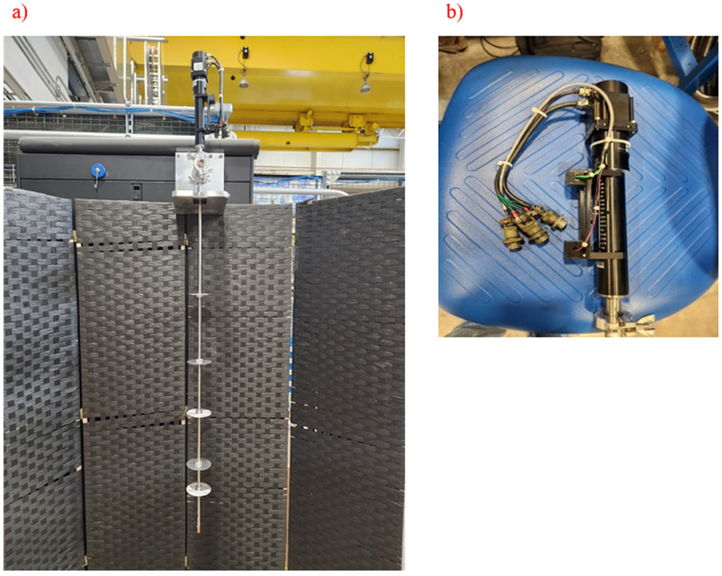
The Cold Neutron Chopper Spectrometer (CNCS) uses a type of vertically translating sample stick called the V-stick, which is designed to use the facilities’ standard sample containers and adaptors (see Figure 2).
The CNCS V-stick has a total travel length of about 100 mm. The precision of this travel is better than 10 µm, while the accuracy is better than 100 µm, making this a very reliable setup. The V-stick was originally assembled for use with a self-shielded superconducting magnet at the CNCS, with the idea of performing vertical scans to align crystal samples in situ to find the position of maximum signal intensity. The ability to perform in situ scans of the sample position reduces the time lost compared to removing and repositioning the sample to find the maximum sample signal intensity. Significant time can be lost from warming and cooling the equipment to adjust a sample’s position (see later sections on the cost of cycling temperatures). Subsequently, the utility of the V-stick was extended to cryostats and closed-cycle refrigerators (CCRs) to measure multiple samples as a sample changer.
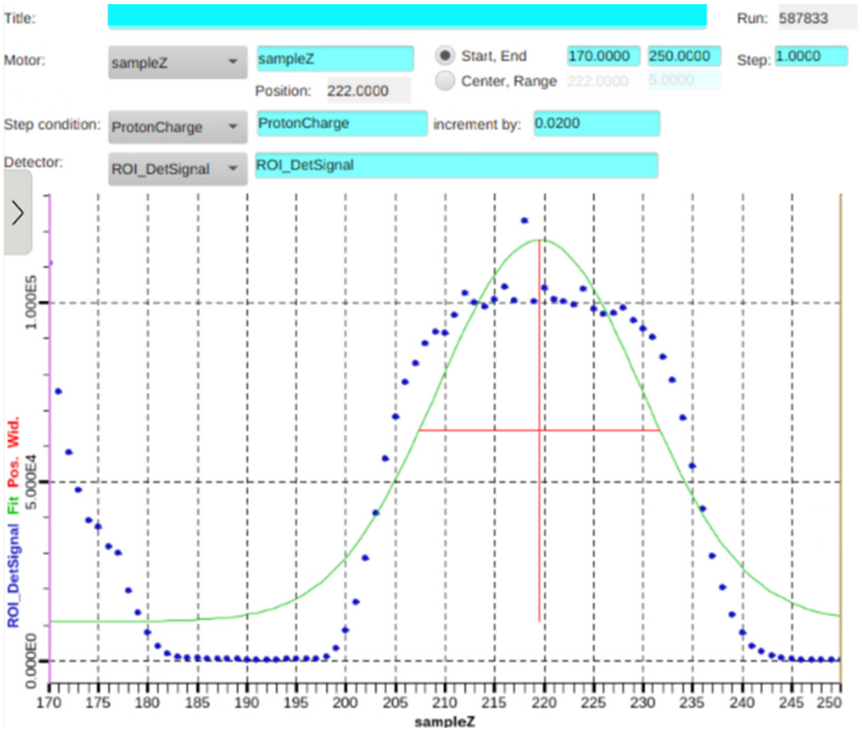
The control software interface for the motorized V-stick has a place to enter an appropriate value to move the sample position directly. In addition, a part of the control software interface called “Alignment” is used to perform programmatic scans. The “Alignment” software needs the following parameters: a region of interest (sample signal), the start and end positions of the sample, step size, and the length of time to collect data at each position. Each data point is plotted, and the appropriate curve is fitted to the data from a list of common fits, which are part of the software interface. The calculated centroid indicates the position(s) of maximum intensity in the sample (see Figure 3).
The BASIS V-stick is expected to operate identically to the system currently used at CNCS.
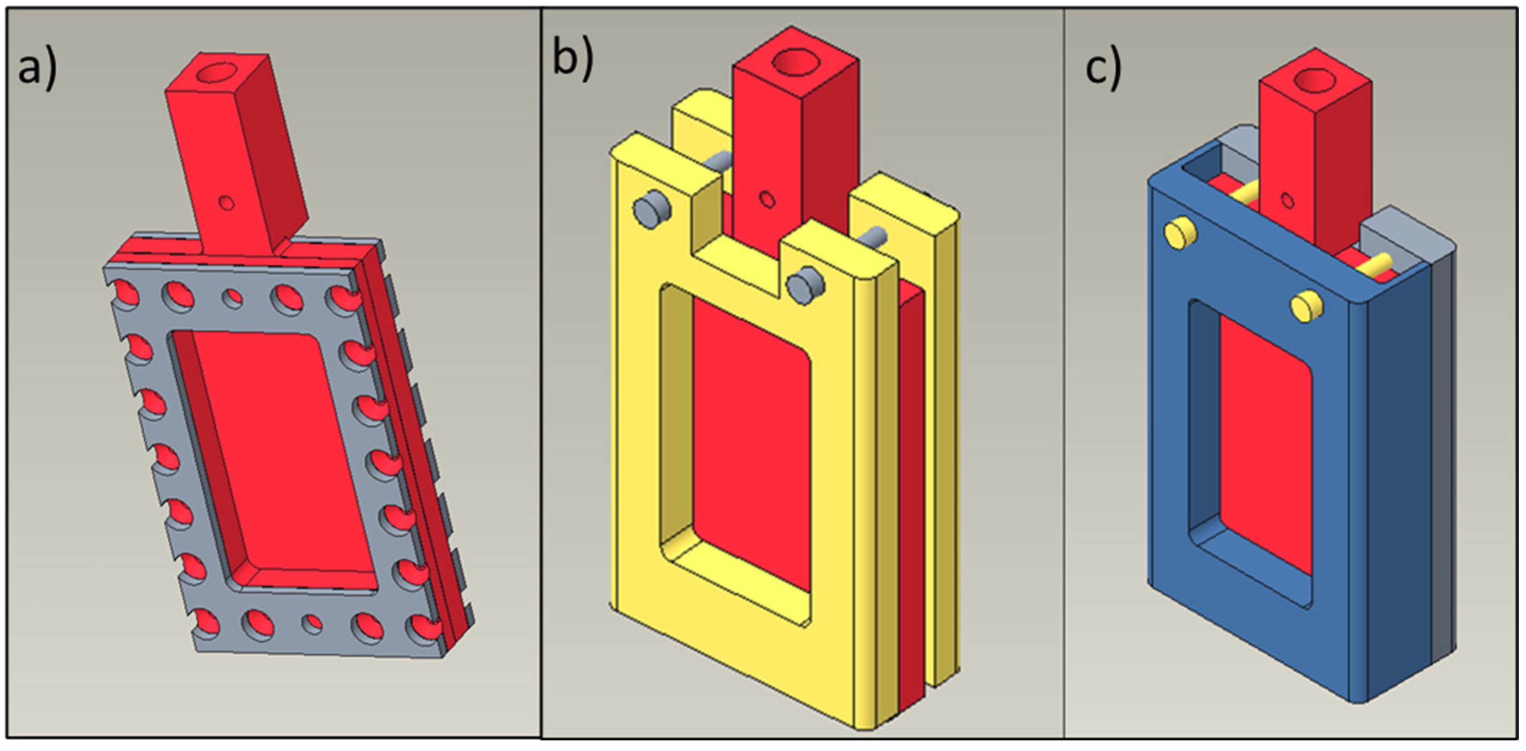
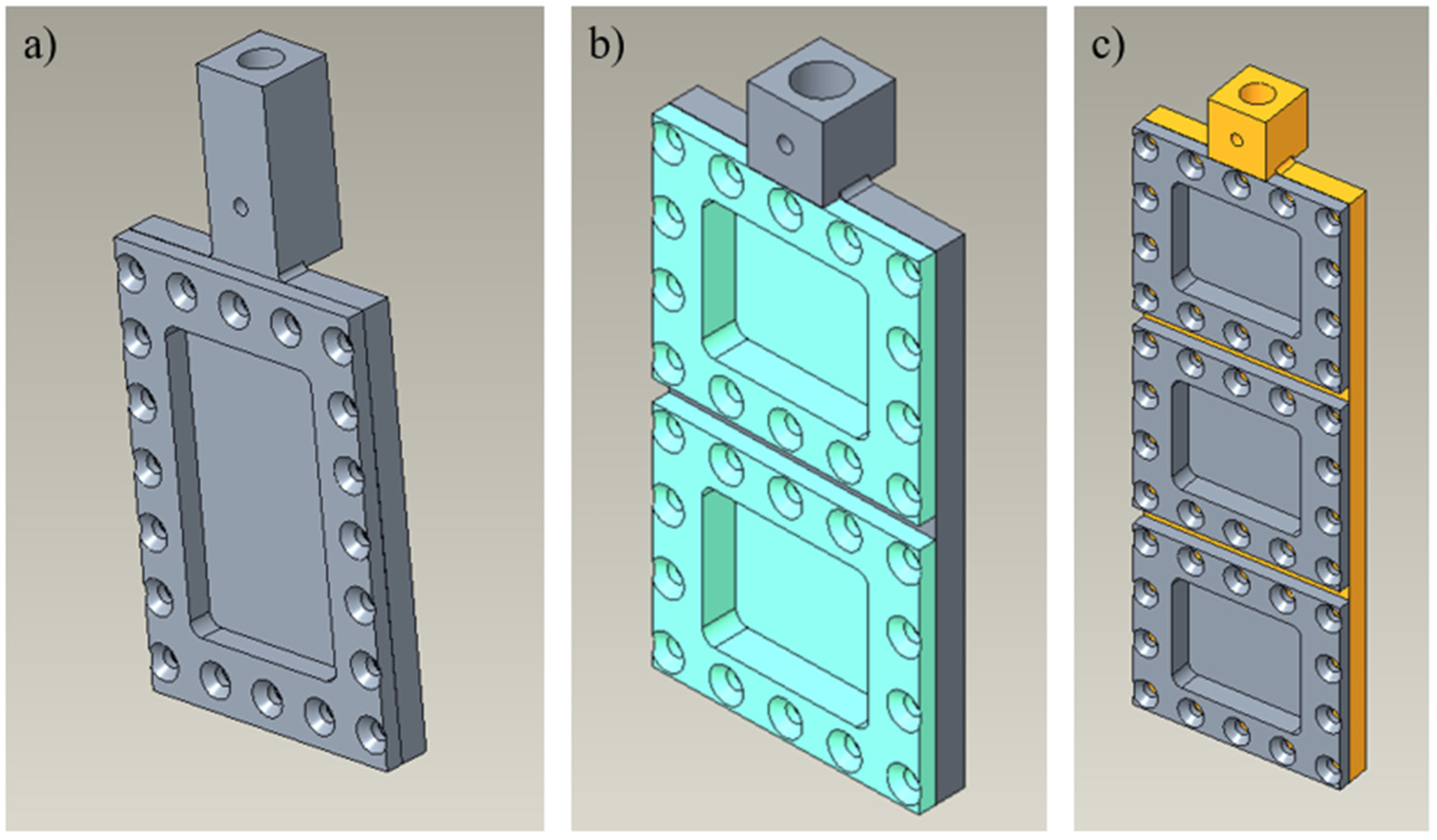
The use of the motorized vertical alignment tool becomes advantageous when working with a flat-plate sample container that has multiple cells. There are currently two styles of flat-plate sample containers available: single and double cell. A triple-cell flat-plate sample container has also been designed and is part of a future CCR upgrade (see Figure 4).
For the BASIS instrument, the use of a V-stick allows us to do two things: (i) be able to scan/align the sample and (ii) to use it as a sample changer. In routine operation, the alignment procedure would typically be performed at the beginning of an experiment to determine the center position of each sample and maximize the neutron beam on the sample. Once these positions have been established, the V-stick can reproducibly translate between them for the remainder of the experiment, with additional alignment scans performed only if needed.
As a test, BASIS used an existing sample stick equipped with a dial-operated linear translator to verify the proposed utility of a V-stick, using a new two-cell flat-plate sample container.

2.3. Double-Cell Flat-Plate Sample Container

In preparation of using the double-cell flat-plate container to test for viability, the BASIS instrument was configured to look at a possible crosstalk between sample cells. A second test would be to check on thermal performance.
At first, we collected the data from both empty cells. For operation involving the two-cell sample container, the BASIS-motorized B4C slits were configured to define a 10 mm × 10 mm incident beam. This aperture corresponds to the intended operating configuration and isolates a single-sample compartment while minimizing scattering from the adjacent compartment and the container hardware. The crosstalk between two cells was tested by keeping a sample (a hydrogen-containing polymer) in the top cell and collecting the data from the bottom cell and vice versa. We also tested crosstalk in scattering by comparing the data collected from the top cell while keeping a sample at the bottom compartment.
To evaluate thermal equilibration between the two sample positions, temperature sensors were mounted at each sample cell, allowing the temperature difference between the compartments to be monitored directly during heating and cooling cycles.

2.4. Automated Helium Pump-and-Purge (HPP) System

CCRs used for neutron scattering experiments rely on a small quantity of helium exchange gas within the sample space to provide efficient thermal coupling between the sample container and the cold head. Without helium exchange gas, heat transfer is dominated by conduction through the sample mount and radiation, resulting in substantially longer cooling and equilibration times. During routine operation, the helium exchange gas must be periodically removed before warming the sample environment and then reintroduced during cooling to provide effective thermal contact. These pump-and-purge procedures are traditionally performed manually using a three-way valve, making the process time-consuming and susceptible to operator-to-operator variation. Automating these operations improves reproducibility while reducing operator intervention and supporting remote instrument operation.
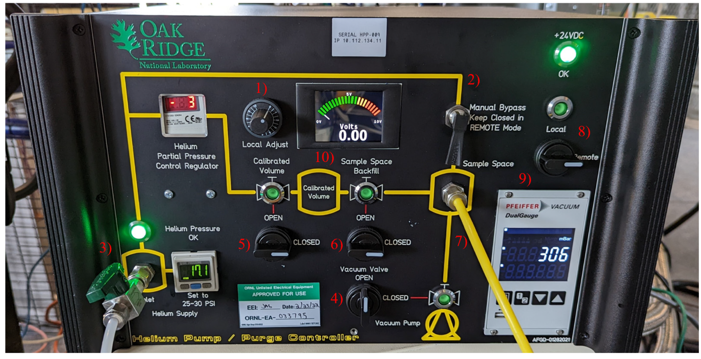
To automate management of the helium exchange gas within the sample space of CCRs, an automated helium pump-and-purge (HPP) controller was developed (see Figure 5). The system improves experimental throughput by providing reproducible evacuation, pump-and-purge cycling, and controlled helium backfilling while reducing operator intervention. At J-PARC, they have an automated gas-handling system called DICE that seems to perform a similar function for QENS experiments [5,6]. The HPP can operate in local (manual) or remote (via computer or programmatic) control modes. The software is fully integrated with the existing instrument control systems.
In local control mode, all operations are performed from the HPP front panel near the CCR. The panel is arranged as a functional flow chart, beginning at the helium gas inlet. Helium can enter the sample space directly through a manual bypass or through a calibrated volume for controlled, repeatable gas delivery using a helium partial pressure regulator and voltage calibration. Operators can fill the calibrated volume, release a measured amount of helium into the sample space, or continuously flow helium directly into the sample chamber. A vacuum valve allows evacuation of the sample space, enabling manual pump-and-purge cycles like those performed with a three-way valve.
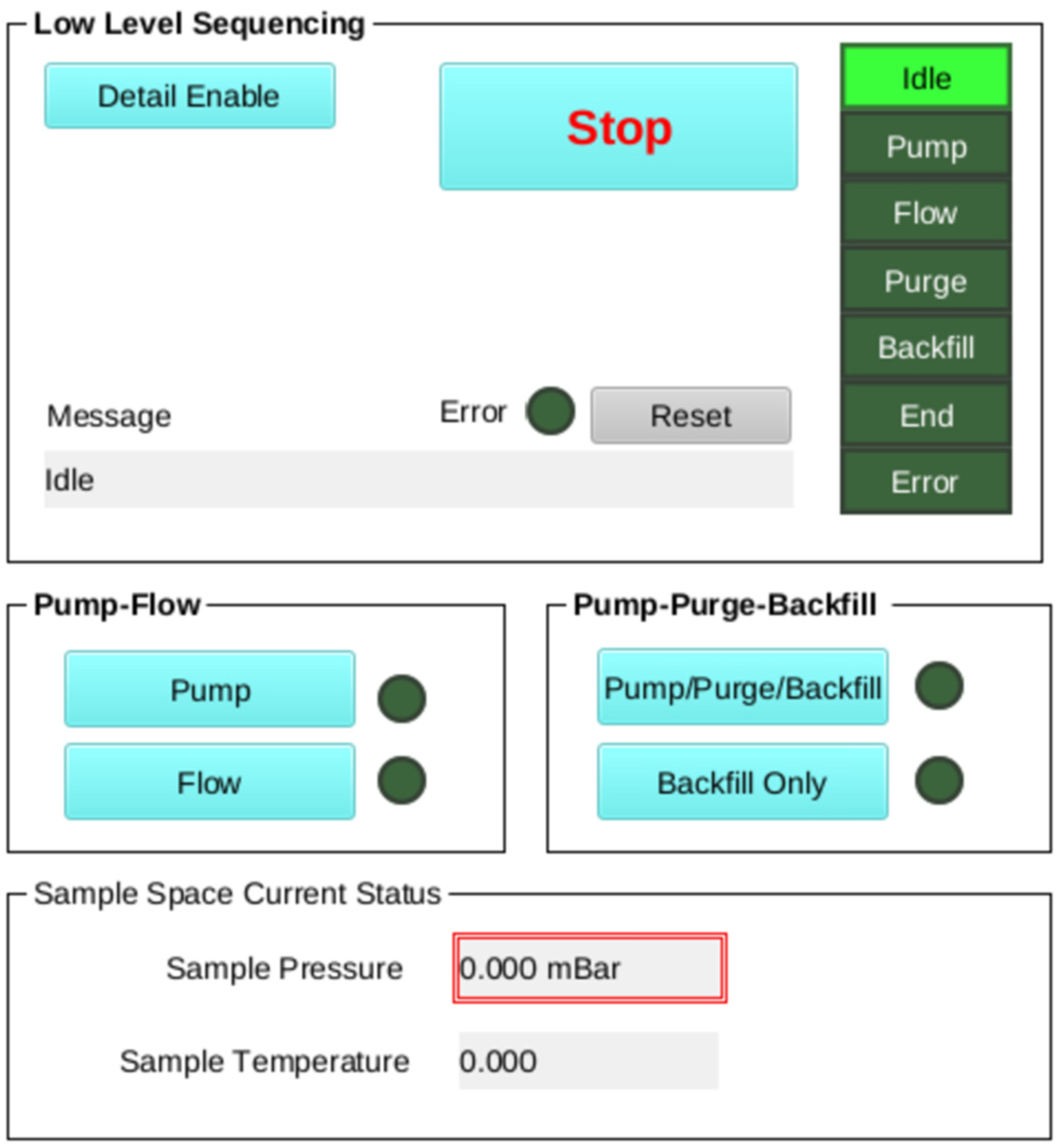
In remote control mode, all local functions are accessible through software. The interface provides controls for pumping, helium flow, automated pump–purge–backfill sequences, and controlled backfilling, along with sample temperature and pressure monitoring (see Figure 6).
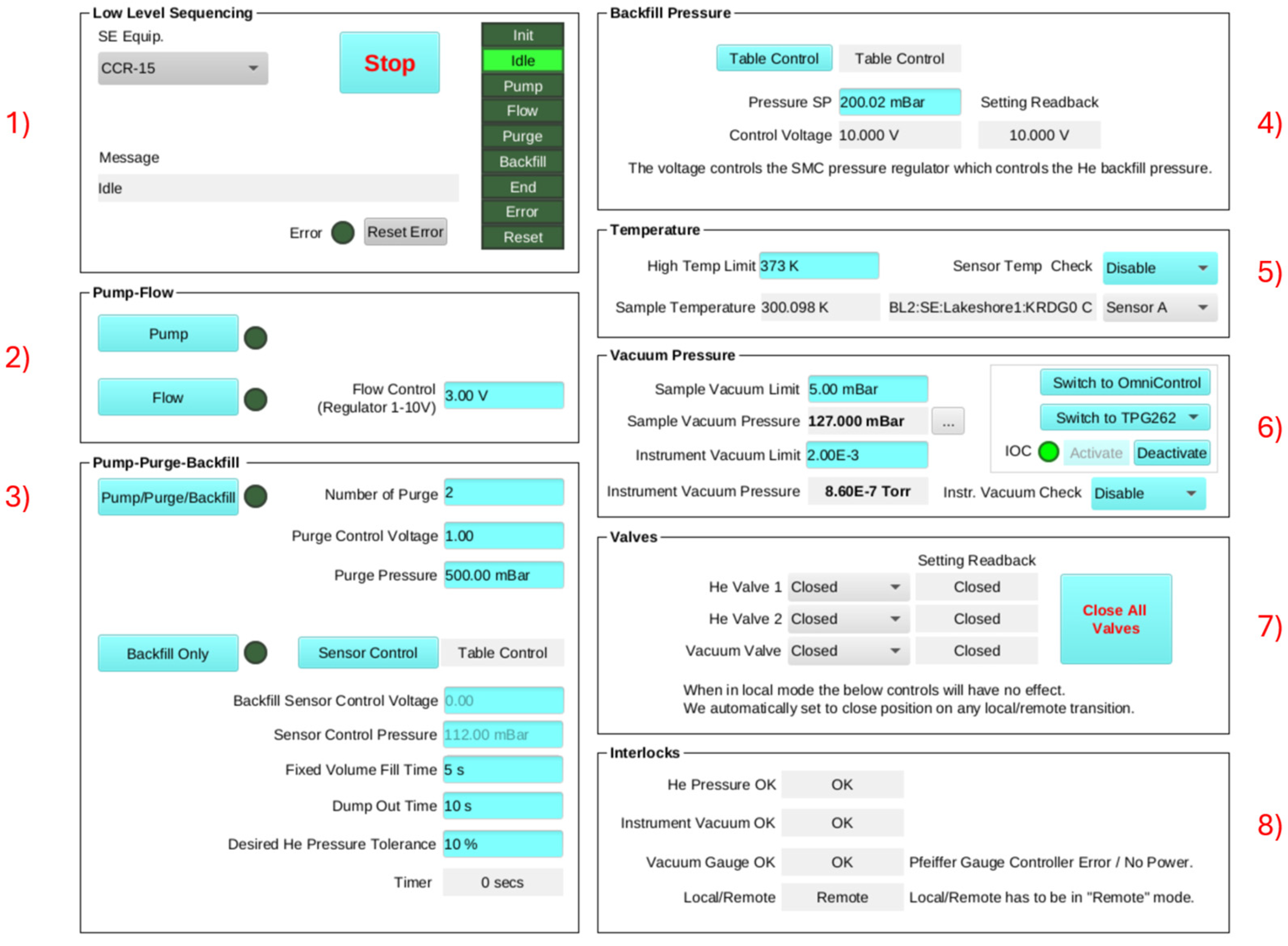
Figure 7 is the operational interface, which shows the system parameters that can be customized for different neutron scattering instruments and CCRs, before returning to the simplified operational interface.
The software consists of eight control modules governing system configuration and gas handling:
  • Low-level sequencing and calibration management.
  • Pumping and helium flow regulation through a 1–10 V control signal.
  • Automated pump–purge–backfill cycling with configurable purge parameters and sensor triggers.
  • Backfill pressure control using direct pressure setpoints or calibrated fixed-volume metering.
  • Temperature regulation with high-temperature interlocks and selectable sensor readback.
  • Vacuum monitoring with interlocks ensures adequate vacuum conditions.
  • Manual helium and vacuum valve control with rapid global isolation capability.
  • System readiness verification through interlocks monitoring helium supply, vacuum integrity, gauge status, and local/remote control state.

3. Results

3.1. Performance of Boron Carbide Masks

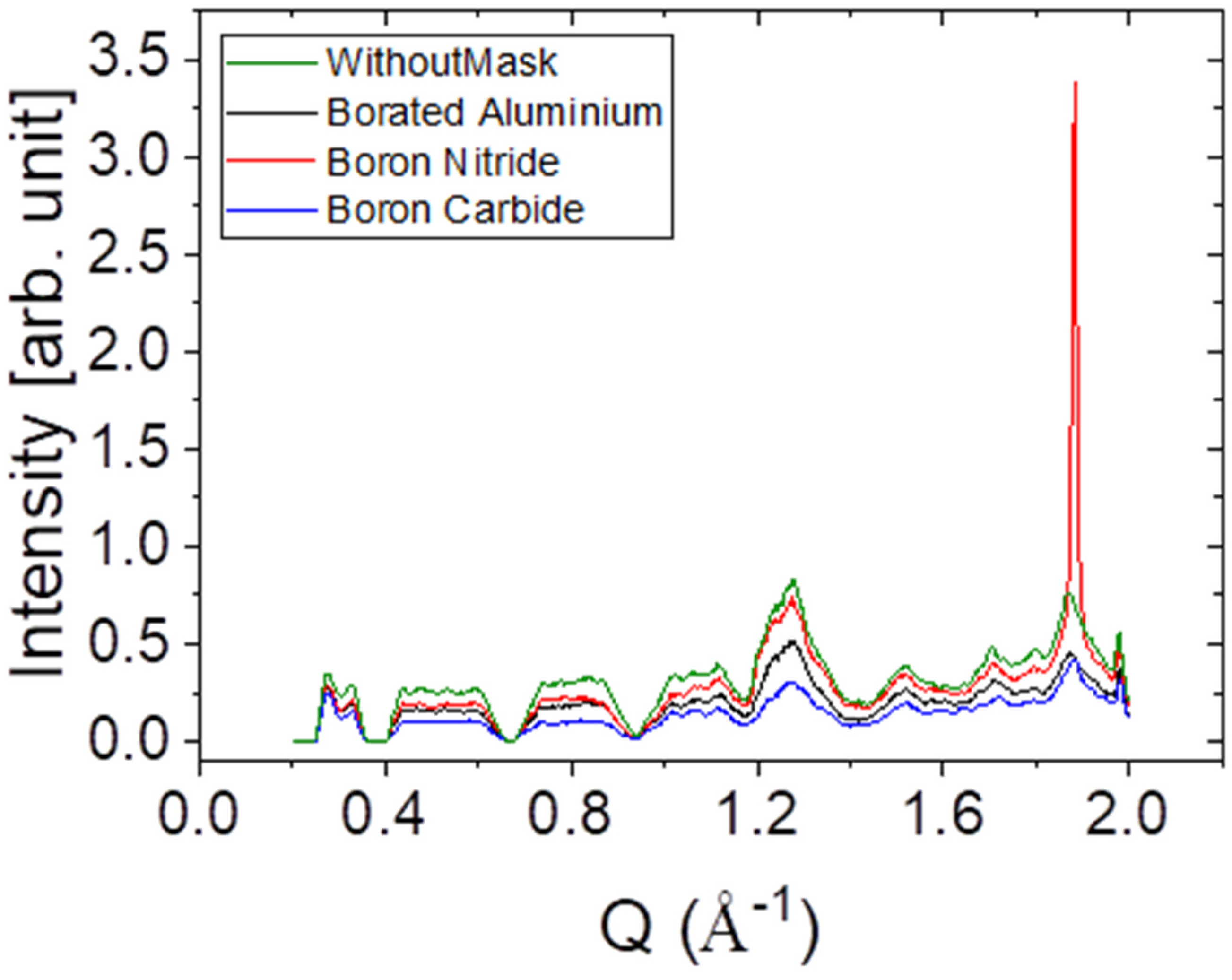
Initially, we considered using a boron nitride mask as a replacement for borated aluminum, which demonstrated a lower background compared to the empty can without a mask (Figure 8). However, there is also a strong (002) Bragg peak [11] around 1.9 Å−1, which could compromise the QENS data. Furthermore, boron nitride is very brittle, which presents additional challenges during processing and handling with repeated uses.
A different approach is to use boron carbide (B4C) to cover the flat-plate sample container, providing a mask that was more re-usable and robust. Figure 8 presents diffraction data collected using the BASIS diffraction detector bank to compare the background scattering associated with different masking materials. The diffraction data shows it does not have any Bragg peaks in the Q-range covered by the spectrometer and has a lower background compared to either borated aluminum or a boron nitride mask.
Over the selected Q-range of 0.32–1.51 (Figure 8), the background reduction depends strongly on mask material. Boron nitride exhibits a reduction of 8.3–29.5% (RMS: 23.7 ± 2.1%), whereas boron carbide provides the greatest reduction at 49.1–67.3% (RMS: 56.8 ± 1.3%). Borated aluminum shows intermediate performance, with reductions of 29.9–40.4% (RMS: 36.2 ± 1.7%).
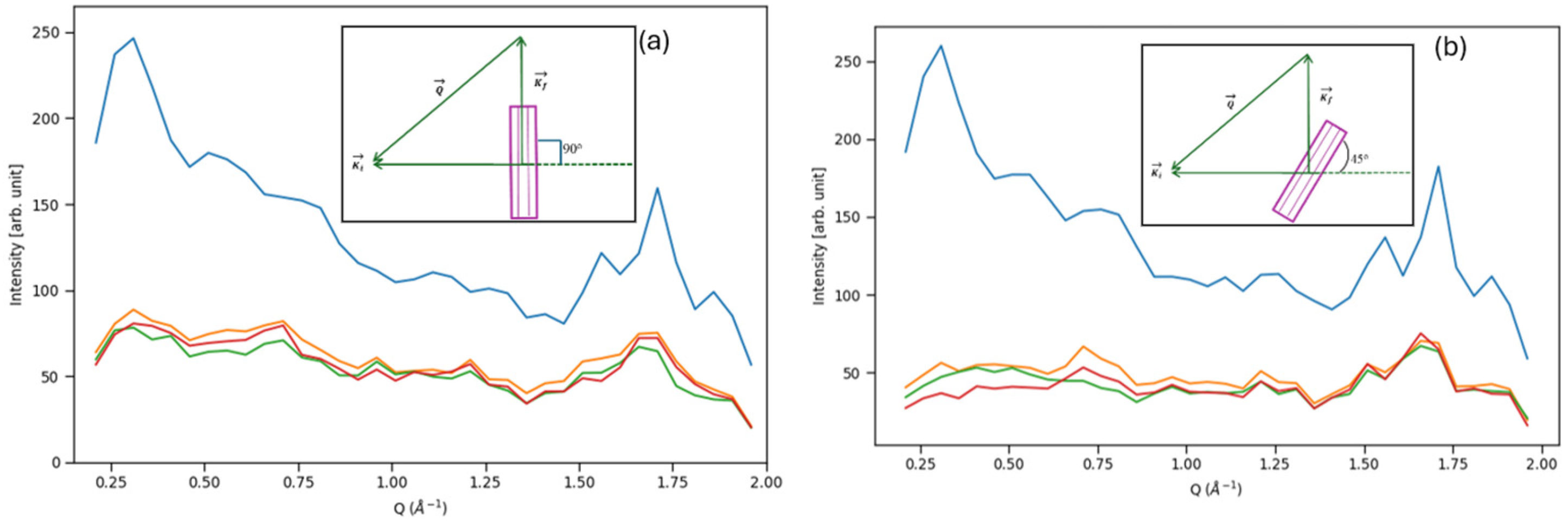
In contrast to Figure 8, the data shown in Figure 9 were collected using the BASIS inelastic detectors to evaluate the effect of the B4C masks under typical QENS measurement conditions. It shows the results of an empty flat plate sample container measuring at two configurations: perpendicular to the beam and 45 degrees to the incident beam. Irrespective of the orientation, the use of B4C masks—whether thin or thick—significantly reduces the background.
The extent of geometric shadowing introduced by the fully enclosed B4C mask depends on the sample orientation. In the 45-degree geometry, the side walls primarily shadow the forward-scattering direction, whereas in the perpendicular geometry the shadowing occurs predominantly over the middle portion of the accessible Q-range. Since the measurements shown in Figure 9 were performed using empty sample containers, the principal observed effect is the reduction of background rather than attenuation of sample scattering.

3.2. Double-Cell Flat-Plate Sample Container Performance

With a double-cell sample container, each sample can be translated into the neutron beam at each temperature, therefore removing the need for temperature cycling. In addition, the double cell has been temperature cycled from 5 to 300 K at discrete steps (5 K, 100 K, 200 K, 300 K) and vice versa to look at the average time needed for both cells to equilibrate in temperature. Cooling and heating conditions were identical, i.e., identical amount of helium exchange gas was used. From these tests, we found that, on average, it takes around 5 min for both cells to be within 1 K of each other and to thermally stabilize. For heating both cells, the average time increased to 7 min, where the difference comes from a slight overshoot in temperature.

3.3. Double Cell Crosstalk Measurements

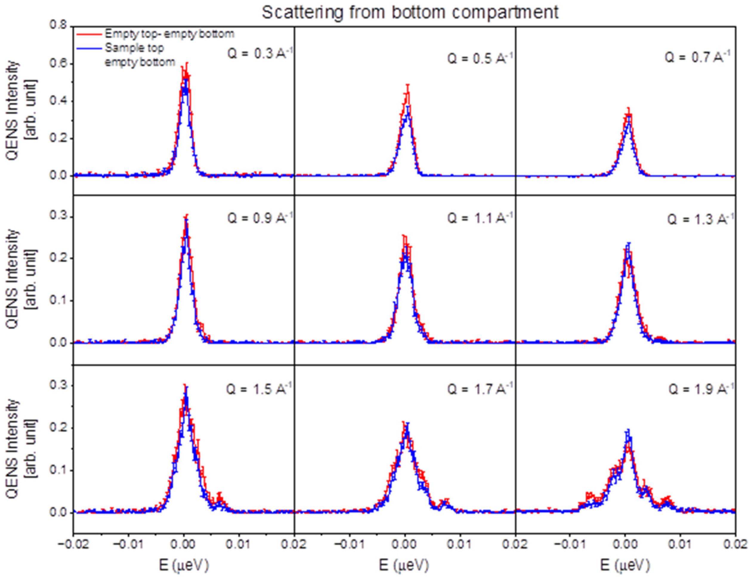
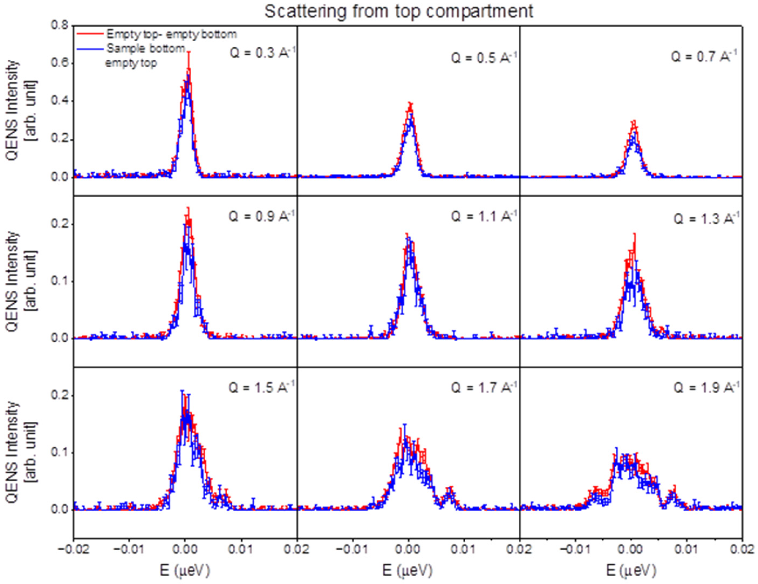
Figure 10 and Figure 11 compare the scattering profile at nine different Q’s from the double-cell flat-plate sample container with both cells empty with that of the scattering where the sample is in the top cell, but the neutron beam is focused on the bottom cell. The scattering profile is nearly identical, suggesting that there is no crosstalk while collecting data from the bottom compartment.
The scattering profile comparison is depicted in Figure 11. The scattering profile is almost identical in this configuration as well. Since the inelastic count rate, and the intensity of the data at all Q’s (Figure 10 and Figure 11), look roughly identical, we concluded that there is no crosstalk while collecting data from each cell separately.

3.4. Helium Pump-and-Purge System Performance

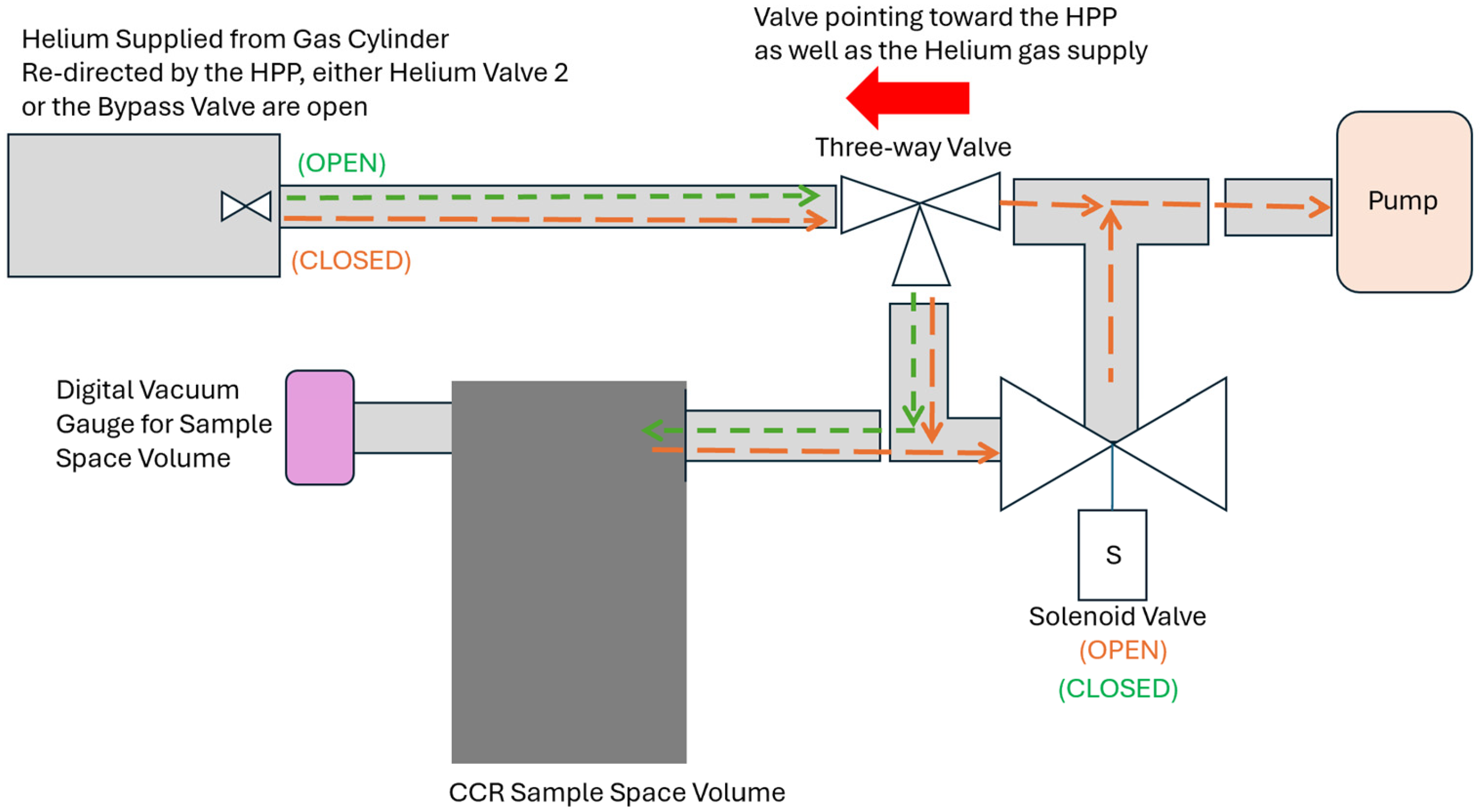
Figure 12 presents how the HPP controller is integrated with a CCR. To make this integration process successful, there needs to be a digital vacuum gauge to read the CCR’s sample space volume pressure, a solenoid valve to create a path to pump on that sample space volume, and a three-way valve to connect the HPP controller to the CCR. The three-way valve also acts as a source of redundancy. The three-way valve is always pointing toward the helium supply, the HPP controller regulates the flow of helium, while the solenoid valve with the HPP controller can provide the correct pumping path. With the HPP controller and a digital vacuum gauge, there is enough feedback information to allow for programmatic control between helium flow and pumping.
Even though the HPP and the CCR are integrated, it is fully reversible as needed, meaning that if there are any complications, the system can be disengaged, and a more traditional three-way valve operation could be used with no loss of beamtime to the experiment.
The reproducibility of fixed-volume operations and sensor-based triggering is approximately ±1 mbar. The calibrated volume was calibrated at room temperature, which is when the entire sample space volume is consistently uniform in temperature. While in operation different neutron scattering instruments will operate slightly differently from one another. Since the CCR is always colder than room temperature, the expected helium gas pressure is always lower than what is predicted, but consistent with the ideal gas law. The sensor-based triggering, while very reproducible, is typically far from the calibration curve. This is mostly due to sensor readback response being too slow and not recommended for more exact volume release of helium gas.

4. Discussion

4.1. Reduction of Background Scattering Using Boron Carbide Masks

Measurements show that masking acts as a uniform suppressor of background across Q, without introducing measurable Q-dependent distortion. Background reduction is reported as the magnitude of fractional attenuation relative to the unmasked sample container to simplify interpretation. Among the tested mask materials boron carbide provides the strongest suppression with long term operational advantages. Borated aluminum was problematic due to supply issues and mechanical wear and the boron nitride’s Bragg peak at low Q-obscuring data only reinforces B4C as the appropriate choice.
Although the thermal performance of the B4C masks was not investigated in this work, the masks are not intended to provide a primary thermal conduction path to the sample container. Consequently, they are not expected to significantly affect sample cooling or equilibration times under normal operating conditions.

4.2. Increasing Experimental Throughput with Multi-Sample Capability

Being able to use multi-cell sample containers can save a significant amount of data collection time during an experiment. The neutron beamtime lost during sample changes and temperature cycling can amount to many hours and, depending on number of samples, even up to a day per experiment.
For a single-sample measurement, the major concern is cycling temperatures, i.e., repeatedly going up and down in temperature. Cooling a sample takes many hours; on average, cooling from 700 K to 10 K takes about 7–8 h. That means we will be losing a significant amount of neutron beamtime while cooling the sample during the measurement. Careful planning can mitigate any unnecessary loss of neutron beamtime. The challenge becomes more prominent when multiple samples are needed to go through the cooling cycle, and if the allocated neutron beamtime is short.
For example, if an experiment involves two samples that each need roughly a day of measurement, then the total time would be about two days. However, using a double-cell flat-plate sample container makes it possible to complete the measurements in a day. This represents a significant improvement in operational efficiency.
This feasibility test using a double-cell sample container at the beamline confirms the possibility of keeping at least two samples at a time. This capability will help minimize the amount of time a user spends on cooling a sample to measure the oftentimes sample-specific instrument resolution function at BASIS. It is encouraging enough to further develop sample containers with more than two cells. At this time, a sample stick with a linear translator was used, but it was not motorized.

4.3. Automation of Gas Handling

The primary advantages of the automated helium pump-and-purge (HPP) system are its reproducibility, remote operation, reduced need for operator intervention, and operational flexibility. Reproducibility is fundamental to the system’s utility, as reliable and consistent helium delivery enables automated control of the sample space atmosphere. By supporting remote operation, the HPP minimizes interruptions to ongoing experiments and allows gas-handling procedures to be performed either on demand or through pre-programmed sequences. This capability reduces the need for manual intervention while improving operational efficiency. An additional benefit of the HPP design is its flexibility; if automated operation does not perform as expected, the system can be immediately disengaged and the integrated three-way valve used to return the sample environment to conventional manual operation without disrupting the experiment.

5. Conclusions

As neutron flux continues to increase at the Spallation Neutron Source, improving both instrument performance and operational efficiency has become increasingly important for maximizing scientific output. In this work, several upgrades to the Backscattering Silicon Spectrometer (BASIS) sample space area were developed and evaluated, including boron carbide (B4C) masking, multi-cell sample containers used with a vertically translating sample stick, and an automated helium pump-and-purge (HPP) system.
The B4C masks reduced background scattering by up to 67%, providing superior performance compared with borated aluminum and boron nitride while introducing no additional Bragg reflections within the instrument’s accessible Q-range. Tests of a double-cell flat-plate sample container demonstrated no measurable crosstalk between sample positions and confirmed stable thermal performance, enabling multiple samples to be measured without repeated temperature cycling and thereby increasing experimental throughput. The automated HPP system provided reproducible gas handling with a precision of approximately ±1 mbar while reducing the need for manual intervention and supporting remote operation.
Collectively, these developments improve signal-to-noise performance, increase sample capacity, and streamline operations at BASIS. The improvements demonstrated provide a practical pathway for supporting higher-throughput neutron scattering experiments and position the instrument to fully benefit from continued increases in neutron flux at the SNS. Future efforts will focus on expanding multi-sample capabilities through motorized sample-changing systems and additional sample container designs to further enhance experimental efficiency.

Author Contributions

Conceptualization, C.S. and R.M.; formal analysis, N.J. and N.C.O.; investigation, C.S., N.J., N.C.O., T.W., J.W., X.G., R.M. and E.M. software, X.G.; writing—original draft preparation, C.S.; writing—review and editing, C.S., N.J., N.C.O., T.W., J.W., X.G., R.M. and E.M. All authors have read and agreed to the published version of the manuscript.

Funding

This research received no external funding.

Data Availability Statement

The data that supports the findings of this study are available from the corresponding author upon reasonable request.

Acknowledgments

Work at ORNL’s Spallation Neutron Source was sponsored by the Scientific User Facilities Division, Office of Basic Energy Sciences, U.S. Department of Energy. The beamtime was allocated to BASIS (BL-2) on proposal IPTS-37114. The authors would like to thank Saad R. Elorfi for his many years of technical expertise and wisdom.

Conflicts of Interest

The authors declare no conflicts of interest.

Abbreviations

The following abbreviations are used in this manuscript:
SNSSpallation Neutron Source
ORNLOak Ridge National Laboratory
STSSecond Target Station
HFIRHigh Flux Isotope Reactor
BASISBackscattering Silicon Spectrometer
PPUProton Power Upgrade
HPPHelium Pump-and-Purge
QENSQuasi-elastic Neutron Scattering
CNCSCold Neutron Chopper Spectrometer
CCRClosed-Cycle Refrigerator
J-PARCJapan Proton Accelerator Research Complex

References

  1. Oak Ridge National Laboratory. Advancing U.S. Leadership: The Science Case for a Second Target Station at the Spallation Neutron Source; Oak Ridge National Laboratory: Oak Ridge, TN, USA, 2026. Available online: https://neutrons.ornl.gov/sites/default/files/STS%20science%20case%202026%20Release_0.pdf (accessed on 7 May 2026).
  2. Oak Ridge National Laboratory. The Science Case for a Proton Power Upgrade; Oak Ridge National Laboratory: Oak Ridge, TN, USA, 2018. Available online: https://neutrons.ornl.gov/sites/default/files/Proton%20Power%20Upgrade%20Science%20Case.pdf (accessed on 7 May 2026).
  3. Mamontov, E.; Herwig, K.W. A time-of-flight backscattering spectrometer at the Spallation Neutron Source, BASIS. Rev. Sci. Instrum. 2011, 82, 085109. [Google Scholar] [CrossRef]
  4. Silverwood, I.P.; García Sakai, V.; Adams, M.A.; Howells, W.S.; Telling, M.T.F.; Demmel, F.; Fernandez-Alonso, F. The IRIS User Guide, 5th ed.; ISIS Neutron and Muon Source, Rutherford Appleton Laboratory: Didcot, UK, 2025. [Google Scholar] [CrossRef]
  5. Tominaga, T.; Kobayashi, M.; Yamada, T.; Matsuura, M.; Kawakita, Y.; Kasai, S. Position-Encoded Automatic Cell Elevator for BL02, J-PARC MLF. JPS Conf. Proc. 2021, 33, 011095. [Google Scholar] [CrossRef]
  6. Kawakita, Y.; Matsuura, M.; Tominaga, T.; Yamada, T.; Tamatsukuri, H.; Nakagawa, H.; Ohuchi, K. Recent Progress on DNA ToF Backscattering Spectrometer in MLF, J-PARC. EPJ Web Conf. 2022, 272, 02002. [Google Scholar] [CrossRef]
  7. Ehlers, G.; Podlesnyak, A.A.; Kolesnikov, A.I. The cold neutron chopper spectrometer at the Spallation Neutron Source—A review of the first 8 years of operation. Rev. Sci. Instrum. 2016, 87, 093902. [Google Scholar] [CrossRef] [PubMed]
  8. Stone, M.B.; Granroth, G.E.; Pajerowski, D.M.; Abernathy, D.L.; Conner, D.L.; DeBeer-Schmitt, L.; Fanelli, V.R.; Goyette, R.; Kolesnikov, A.I.; Mills, R.; et al. Sample changers for direct geometry neutron chopper spectrometers. Sci. Rep. 2025, 15, 31936. [Google Scholar] [CrossRef] [PubMed]
  9. Vong, D.; Novak, E.; Ruiz-Rodriguez, M.; Elorfi, S.; Thomas, B.; Morris, A.; Moule, A.; Daemen, L. Compact, portable, automatic sample changer stick for cryostats and closed-cycle refrigerators. Rev. Sci. Instrum. 2023, 94, 085108. [Google Scholar] [CrossRef] [PubMed]
  10. Ehlers, G.; Podlesnyak, A.A.; Niedziela, J.L.; Iverson, E.B.; Sokol, P.E. The new cold neutron chopper spectrometer at the Spallation Neutron Source: Design and performance. Rev. Sci. Instrum. 2011, 82, 085108. [Google Scholar] [CrossRef] [PubMed]
  11. Yan, Z.; Abdelkader, A.; Day, S.; Tang, C.; Casiraghi, C.; Mirihanage, W. In situ probing of the thermal treatment of h-BN towards exfoliation. Nanotechnology 2021, 32, 105704. [Google Scholar] [CrossRef] [PubMed]
Figure 1. Flat-plate configurations: (a) borated aluminum masks (front and back) with holes for screws, (b) two flat B4C masks that sandwich the flat-plate sample container, and (c) a configuration that has the entire flat-plate sample container encased in B4C. The only path for neutrons is the opening on the front and back.
Qubs 10 00018 g001
Figure 2. (a) A vertical translating stick, or V-stick; this is the one used for BL-5, CNCS. (b) A close-up of the motorized top, which experienced 100 mm of linear travel.
Qubs 10 00018 g002
Figure 3. An example of the CNCS making an alignment scan in trying to determine the maximum intensity of a sample that is to be measured. The blue dots represent collected data from scattered neutrons, the solid green line is a fit to this data, and the red cross is the calculated center of the fit.
Qubs 10 00018 g003
Figure 4. Different versions of flat plate sample containers for BASIS: (a) standard single cell, (b) double cell, and (c) the proposed triple cell.
Qubs 10 00018 g004
Figure 5. The HPP front panel display: (1) Voltage dial and readback used to adjust the partial pressure control regulator; (2) manual bypass valve; (3) helium supply inlet and digital regulator; (4) vacuum valve to pump the sample space volume; (5) calibrated volume valve or helium valve 1; (6) sample space backfill valve or helium valve 2; (7) helium supply outlet going to the sample space volume; (8) switch between remote and local operations; (9) vacuum gauge for the sample space volume; (10) calibrated volume.
Qubs 10 00018 g005
Figure 6. The simplified computer interface for the helium pump-and-purge (HPP) system.
Qubs 10 00018 g006
Figure 7. Detailed software interface for the HPP system showing configurable operating parameters for different neutron scattering instruments and CCRs. Once set, these parameters generally will not need to be adjusted again. Items (1–8) are briefly explained in the text.
Qubs 10 00018 g007
Figure 8. Neutron diffraction data collected with BASIS diffraction detectors compare the neutron diffraction profile of the flat aluminum plate sample holder without and with masks of different compositions. Data was collected while operating the BASIS choppers at 60 Hz, with the central bandwidth of the incident neutron selected to be at 6.4 Å.
Qubs 10 00018 g008
Figure 9. Scattering measured with the BASIS inelastic detectors show diffraction patterns from the empty flat plate sample container measured with and without B4C masks under two different scattering geometries. (a) Flat plate perpendicular to incoming neutron beam; (b) flat plate is oriented at 45 o to the incoming beam. Insets illustrate the corresponding scattering geometries, along with scattering vector, Q = K i K f , where K i   a n d   K f are incident and scattered neutron wave vectors, respectively. The lines in the plot represent data collected using different masks and thicknesses: Blue lines: empty can without a mask; yellow lines: thin B4C masks placed in front and at the back of the can; green lines: thick B4C mask in front and at the back of the can; red line: thick B4C mask covering the front and the sides, and with a thin B4C mask at the back of the can.
Qubs 10 00018 g009
Figure 10. A comparison of QENS data collected from a double-cell flat plate having a polymer sample at the top cell and collecting the neutron scattered from the bottom cell at the indicated Q-Values.
Qubs 10 00018 g010
Figure 11. A comparison of QENS data collected from a double-cell flat plate having a polymer sample at the bottom cell and collecting the neutron scattered from the top cell at the indicated Q-Values.
Qubs 10 00018 g011
Figure 12. This is a schematic that shows (1) how the HPP is integrated into the CCR and (2) how the piping works for helium gas flow and for pumping.
Qubs 10 00018 g012
Disclaimer/Publisher’s Note: The statements, opinions and data contained in all publications are solely those of the individual author(s) and contributor(s) and not of MDPI and/or the editor(s). MDPI and/or the editor(s) disclaim responsibility for any injury to people or property resulting from any ideas, methods, instructions or products referred to in the content.