Abstract
In the present study, a new approach to the installation of fiber Bragg grating (FBG) sensors in three asphalt pavement layers (the surface layer and both base layers) was implemented for the first time in Belgium. Fiber Bragg grating sensors (FBGs) are diagnostic tools that accurately and efficiently monitor in situ structural behavior. However, nowadays, this technology is not commonly used in asphalt due to its application restrictions under installation and service conditions. FBGs are fragile and break easily under loading. Therefore, there is a need for suitable protection of FBG sensors if they are to be installed during the rough construction process and exposed to heavy-duty loading afterwards. The main objective of the present study is to show the FBG results only for the initial construction process, and, if successful, to continue studying this FBG monitoring system and to plan the next research step by adjusting the system for its application in heavy-duty pavements. Two approaches to FBG installation in three asphalt layers (placed at the bottom of each layer) were tested in the present study: (1) installation of FBGs in prefabricated asphalt specimens in the base layer, directly on the base, and (2) installation of FBGs on the surface of the previously constructed asphalt layer. Both innovative approaches allow the implementation of FBGs without sawing the whole layer into two parts. The obtained results proved a survival rate of 100% for the FBGs. It can be concluded that these new described methods of FBG installation—using a cross-section configuration to carry out strain measurements in two directions (transverse and longitudinal)—can be applied for the monitoring of heavy-duty pavements, while providing the possibility to further re-evaluate current pavement design methods used in Flanders (Belgium).
1. Introduction
Pavement design must be continuously improved to produce solutions that are less disruptive to the environment, and must be economical and of a higher quality, considering current traffic loading. Yearly, many billions of euros are spent on road construction and maintenance in Europe. Therefore, more efficient methods of pavement design are essential. A considerable number of researchers have put emphasis on: (1) understanding the aging process of road pavements, (2) developing solutions to decrease or eliminate cracks and structural deformations due to traffic and climatic fatigue [1], (3) analyzing rutting performance, and (4) predicting road behavior to ensure highway and urban roads have a longer service life. The majority of currently used pavement design methods were introduced more than 30 years ago [2]. Since then, the monitoring of pavements and passing vehicles has been vigorously developed with the growth of information and sensing technology. Conventional asphalt heavy-duty pavement road structures were not designed for the load spectra used nowadays and, therefore, deteriorate much faster compared to the designed service life. In the last three decades, traffic volume has dramatically increased, especially the overloaded truck traffic. With the increasing traffic on flexible roads, rutting has become one of the most significant problems for road pavements, especially in urban areas due to the channelized traffic and overload, and on heavy-loaded asphalt pavements.
Pavement design is a rather complicated process, because layered elastic theory offers calculation results that are incongruent with the real state of pavements, ignoring the uneven, anisotropic and nonlinear stress–strain relationship of paving materials. The process is divided into two distinct parts: an understanding of characterization of the materials used and assessment of vehicular loading; and the application of these factors to a design method.
Much research has focused on the pavement performance of asphalt mixes, which shows unique physical properties. Asphalt material is often considered—for simple calculations—to behave in a linearly viscoelastic-plastic manner; thus, its mechanical response is a continuous function of time and temperature. Considering the stiffness of the material, its behavior at lower temperatures is equivalent to a higher strain rate, such as the strain on pavement due to moving traffic. In the case of high stiffness, the strain on asphalt should ideally be measured directly for the greatest accuracy; however, instruments capable of making such measurements are not generally available. In fact, a higher temperature or a lower strain rate, such as the strain caused by the subsidence of the foundation, results in an extremely low elastic modulus of asphalt; furthermore, rigid instruments, such as electrical foil strain gauges, are often assumed to have negligible stiffness. In such cases, the stress transferred from the asphalt to an embedded sensor decreases drastically, thereby reducing the sensitivity of the sensor reading [3].
It is challenging to devise an efficient method to determine realistic mechanical properties of pavement [4]. For this reason, since the early 1990s, there has been interest in improving all kinds of sensors to exhibit strain, stress, and displacement with a much higher precision [5]. A number of different technologies have been developed over the last years, and, among them are fiber Bragg grating-based sensors. A fiber Bragg grating (FBG) is a distributed mirror in a short segment of the optical fiber, reflecting a limited wavelength range and transmitting all others. The working principle is based on a periodic variation of the refractive index of the fiber core, which acts as a wavelength-selective filter with a central reflecting wavelength. The sensing information is encoded in the optical spectrum, which is reflected by the fiber Bragg grating. An external perturbation (temperature, strain) causes the central Bragg wavelength to shift [6]. FBG is one of the most used technologies in commercial applications in the fields of optical communication and composite materials [7], temperature sensors, and strain sensors due to several inherent advantages over other technologies: accuracy and range, lightweight, small size, self-referencing, multiplexing, immunity to electromagnetic interference, and environmental ruggedness [8]. The tensility or compression of the grating can lead to a period change when the FBG sensor (FBGs) is deformed by outside temperature change or loading. While FBGs can be used to immediately replace electrical strain gauges and thermocouples for strain measurement and temperature measurement, respectively, the use of unpackaged FBGs is not practical when field measurements are required. Consequently, a number of different designs have been developed to allow for an easier installation of FBGs. Sensors aimed at measurements other than strain and temperature have also been developed. In this case, the sensor packaging includes mechanisms capable of converting the measurement to the strain on the FBG.
FBGs have been applied to the measurement of strain at multiple points on a line and have been studied for application in asphalt layer monitoring [9]. Lu et al. [10] studied the strain change at the gap opening by wheel loading, whereas Iten et al. [11] successfully detected settlement by installation of fiber optic sensors, using Brillouin optical time domain analysis (BOTDA) technology, along the hillside road boundary in an 89 m trench on the surface of an asphalt road pavement. Imai et al. [3] have experimentally proved that embedded FBGs, coated with an adhesive polyethylene composite of 5 mm in diameter, have the potential to detect asphalt behavior directly, even if the asphalt exhibits a low modulus of elasticity, because the flexible FBGs have negligible reinforcement effects on the strain field. Tan et al. [12] proved that FBGs could identify weak, compacted areas based on different FBG sensor response values and could serve as a long-term monitoring system of pavement structural behavior. Liu et al. [13] made co-line and integration designs of FBG sensors and BOTDR (Brillouin optical time domain reflectometry) sensors, which could provide real-time subgrade settlement and rutting information. The potential and feasibility of the practical application were proved in lab tests. FBG sensors could also be applied to, and worked well in, severe environments, like high temperature or moisture conditions.
However, it must be noted that, in most cases of practical engineering, test methods in the laboratory are not suitable to measure the stress and strain of pavement structures under different loading conditions. FBG is a diagnostic tool to accurately and efficiently monitor in situ structural behavior. Although, FBG is not commonly used in asphalt technology due to its application restrictions during rough construction processes. FBG sensors are rather fragile and can break easily under loading. The harsh working environment requires the sensors to endure high temperatures (up to 160 °C), moisture, high compaction force, repeated heavy loading, and so on, and have a large coverage. It must be noted that most of the traditional sensors for other civil structures cannot be used for pavement structures directly [14].
In the present study, two new approaches to FBG installation in three asphalt layers were implemented in a bicycle path structure at the University of Antwerp (Belgium) for testing innovative technologies for the asphalt industry. The main objective of the present study is to show FBG results for the initial construction process, and, if successful, to continue studying the FBG monitoring system and to plan the next research step by adjusting the system for its application in heavy-duty pavements.
2. Materials and Methods
2.1. Fiber Bragg Grating (FBG) Sensors
FBGs are rather fragile and can break easily under loading; therefore, there is a need for suitable protection of these sensors if they are going to be installed during the rough construction process. For appropriate protection, which guarantees the accuracy of both strain and temperature measurements, in the present study, commercially available, organic modulated, ceramic-coated Draw Tower Gratings (DTG®), embedded in a glass fiber reinforced plastic (GFRP) round profile with an outer diameter of 1 mm and protected with an additional high-density polyethylene (HDPE) coating with outer diameter of 0.5 mm, were used (see Figure 1). These DTGs can measure very high strain levels (>10,000 µm/m) and are supposed to show an excellent long-term stability under mechanical fatigue conditions. Draw Tower Gratings (DTG®s) are produced during the drawing process of the fiber itself, before the primary coating is applied. Considering that it is a cost-effective production process for high quality fiber Bragg gratings, it offers unique characteristics, such as extremely high breaking strength, an operational temperature range of up to 200 °C (for ORMOCER®), insensitivity to bending, spliceless array configurations, and uniform coating coverage, which are very important for application of these fibers in asphalt pavement.
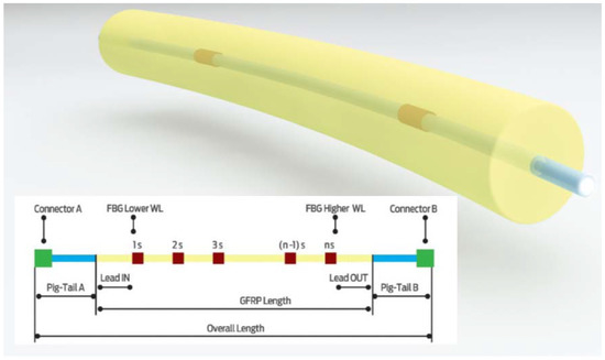
Figure 1.
Fiber Bragg grating (FBG) configuration with Draw Tower Gratings (DTG®) [15].
2.2. Installation of FBG Sensors in Asphalt Layers
In the present study, FBG chains of 30 DTG® (1529.7–1567.4 nm) and 5 DTG® (1530–1558 nm) were selected for installation in each of three superimposed asphalt layers (the surface layer and both base layers). The FBGs were placed in a cross-section configuration in order to carry out measurements in two directions—transverse and longitudinal directions (in a bicycle path with width of 4 m and length over 3.2 m) (see Figure 2b). The asphalt mix was applied at a temperature between 120 and 160 °C. It was very important to allocate each fiber at the bottom of each layer in transverse (T) and longitudinal (L) directions. Two new approaches to FBG installation in three asphalt layers were tested: (1) installation of FBGs in prefabricated asphalt in the bottom of the base layer (see Figure 2a) and (2) installation of FBGs in the surface of the previously constructed asphalt layer (see Figure 2b). Both innovative approaches allow the implementation of FBGs without sawing the whole layer into two parts. The FBG configuration is shown in Figure 3.
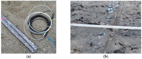
Figure 2.
Installation of FBGs in prefabricated asphalt in the base layer (a) and installation of FBGs in the previously constructed asphalt layer (b).
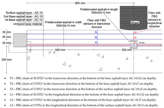
Figure 3.
FBG configuration in three asphalt pavement layers (cross-section of road) [16].
After an extensive literature review study, it was concluded that the protection of sensors is an ongoing challenging issue to deal with, especially the protection of FBG sensors installed at very high asphalt temperatures and during heavy compaction loadings. Several protection measures, including fiber reinforced polymer (FRP), steel tubing, and carbon fiber reinforced epoxy resin coatings, have been shown to be able to provide adequate protection. However, in order to guarantee the survival of FBGs during the installation process in the base asphalt layer in this case study, it was decided to embed them in prefabricated asphalt specimens (see Figure 4) and adjust on-site during the construction process.
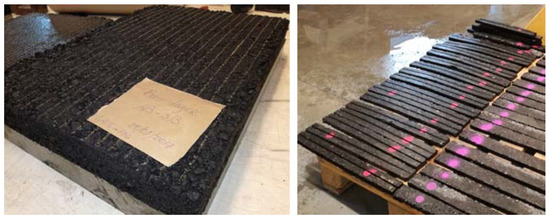
Figure 4.
Prefabricated asphalt (AC-14) specimens with grooves for preparation of FBG embedment.
For this first approach to FBG installation, asphalt slabs with dimensions 600 × 400 × 50 mm were produced under laboratory conditions, with the same asphalt mix composition as the base layer used during the bicycle path construction process. The slabs were sawn into specimens with dimensions 500 × 50 × 15 mm, and a groove with a depth of 2 mm was made in each specimen. The FBGs were positioned in a groove of the prefabricated asphalt specimens on-site and covered with a thin layer of mastic to keep FBGs in the desired position inside the groove. Prefabricated asphalt specimens were connected to each other on-site by gluing them together with a layer of mastic. Prefabricated asphalt specimens were placed with the groove facing down on the unbound material base layer. In order to avoid collapse of the prefabricated asphalt specimens, steel plates with dimensions of 340 × 300 × 5 mm were placed on top of the specimens during the construction process when the asphalt truck and the paver were driving over them (see Figure 5).
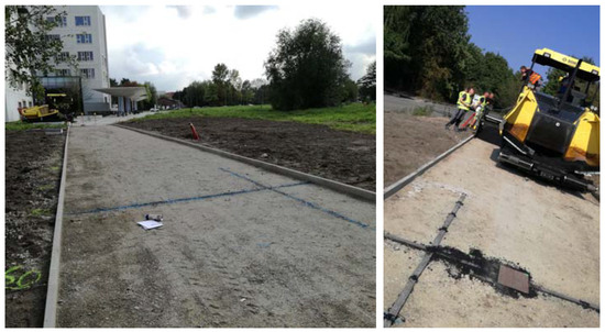
Figure 5.
Installation of FBGs in the base asphalt layer directly on the base (first approach).
2.3. Monitoring of FBGs during the Pavement Construction Process
The installation of the FBG monitoring system was a part of a larger project—CyPaTs (www.uantwerpen.be/cypats), in which a bicycle path (length—96 m and width—4 m) was accomplished over 3 days (one asphalt pavement layer per day). During the first day, FBGs (T1 and L1) were installed in the prefabricated asphalt specimens, and the first strain measurements were carried out after the first base layer (AC-14) was laid down. FBGs (T2 and L2) were installed in grooves (in the upper section of this base layer) after 2 h on the same day. In order to ensure the bonding of the interfaces between asphalt layers, a tack coat was applied (see Figure 6). During the second day, FBGs (T1, T2, L1, L2) were monitored during construction of the second base layer (AC-10) while the asphalt truck and the paver were crossing the sensing zone. FBGs (T3 and L3) were installed in grooves after 2 h on the second day. During the third day, all FBGs in T and L directions were monitored during construction works. The strain and temperature data were obtained using an interrogator FBG-SCAN 808D with eight channels (1510–1590 nm wavelength range, 250 Hz measurement speed for all channels).
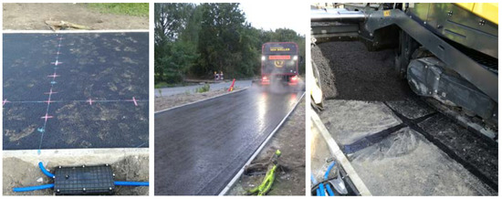
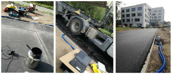
Figure 6.
Installation of FBGs in two asphalt base layers (second approach).
3. Results and Discussion
During the construction process, it was observed that the new method, with prefabricated asphalt specimens as part of the first asphalt base layer (AC-14), is quite reliable and all FBGs had a survival rate of 100%. However, for the high-volume applications, this method had to be adjusted for an easy application on-site. Considering that stiffness and homogeneity of the asphalt base layer are higher than those of an unbound base material layer, for the second approach of FBG installation, it was decided to groove the layer to a depth of 2 mm on top and embed the FBGs by covering them with a thin layer of mastic. The ease of the process of on-site installation of FBGs in the base layers was shown; however, it is not applicable in the case of the lowest base layer. The preparation of grooves in the next two asphalt layers on-site was possible as shortly as 2 h after compacting the respective asphalt layer (see Figure 6). The monitoring of the survival rate of FBGs showed positive results: all embedded sensors worked during and after construction.
The response of the sensors (strain vs. time) during the construction process can be seen in Figure 7, Figure 8, Figure 9, Figure 10, Figure 11, Figure 12, Figure 13, Figure 14 and Figure 15, where the sensors show a positive shift (tension) or negative shift (compression) during loading. The first registered response of the sensors with no loading 2 h after the installation of the first base layer (AC-14) is shown in Figure 7. With this technology, it was demonstrated that the deformations in the structure can be monitored very accurately; for example, during monitoring, it was observed that axle loading was not equally distributed, and that the response of the sensors under the right wheel (T’—black line) had higher values than those under the left wheel (T’’—red line) of the four-axle truck and paver. Considering this, two sensors from each fiber in the transverse direction were considered for the analysis: one sensor (T’) under one loading point (in the center beneath the wheel) in the three asphalt layers in T direction, and another sensor (T’’) closer to the edge of the road during the 3-day paving process. In Figure 7, it is clear that the responses of T1’ and T1’’ show a difference in strain value, meaning that one side of the road is under higher compression than the other side.
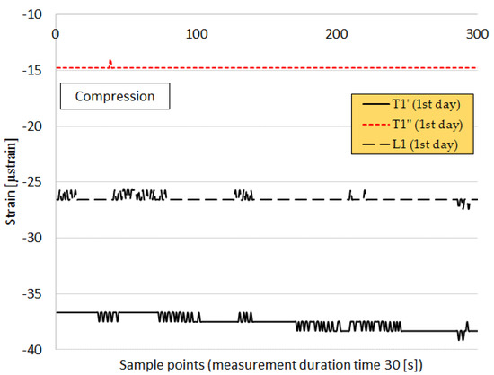
Figure 7.
Strain values of sensors T1’, T1’’, and L1 during the construction of CyPaTs asphalt pavement on the first day at a temperature of 64 °C on the surface of the first base layer AC-14.

Figure 8.
Monitoring of FBGs during the second day during the construction of the second base layer of the CyPaTs bicycle path.
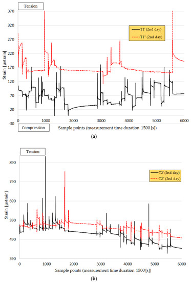
Figure 9.
Strain values of sensors: (a) T1’ and T1’’ and (b) T2’ and T2’’ during the construction of CyPaTs asphalt pavement on the second day.

Figure 10.
Monitoring of FBGs on the third day during the construction of top layer of the CyPaTs bicycle path at a temperature of 24 °C on the surface of the second base layer AC-10.
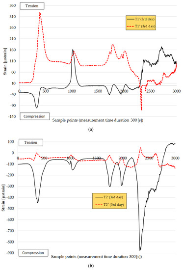
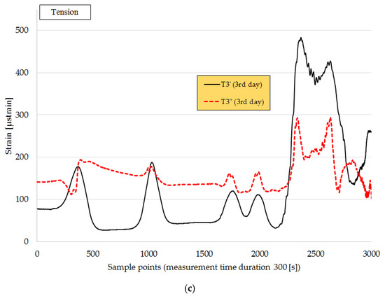
Figure 11.
Strain values of sensors: (a) T1’ and T1’’, (b) T2’ and T2’’ at a temperature of 21 °C, and (c) T3’ and T3’’ at a temperature between 24 and 29 °C during the construction of the CyPaTs asphalt pavement on the third day.
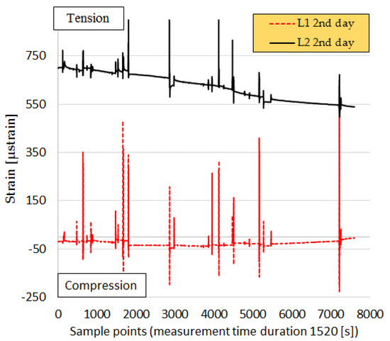
Figure 12.
Strain values of sensors L1 and L2 during the construction of the CyPaTs asphalt pavement on the second day.
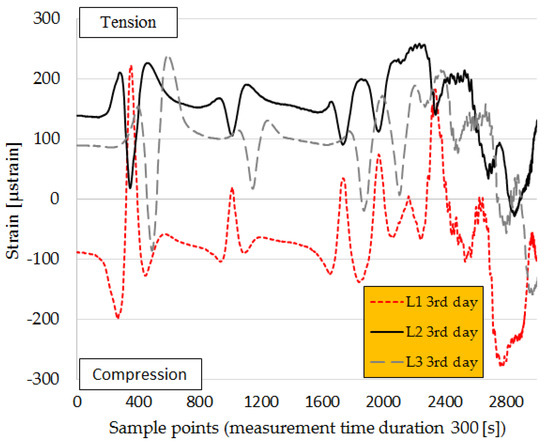
Figure 13.
Strain values of sensors L1, L2, and L3 during the construction of CyPaTs asphalt pavement on the third day.
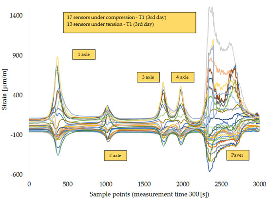
Figure 14.
Monitoring of T1 on the third day of the paving process when the four-axle truck and the paver drove along the FBG chain of 30 DTG® (L1) embedded under the first base asphalt layer (AC-14) [17].
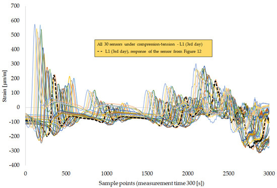
Figure 15.
Monitoring of L1 on the third day of the paving process when the four-axle truck and the paver drove along the FBG chain of 30 DTG® (L1) embedded under the first base asphalt layer (AC-14).
During the construction of the pavement on the second day, it was requested to drive the truck and paver over the sensing zone in such a way that the right wheels drove along the FBGs in the L direction. In Figure 8, it can be seen that this was almost achieved. It was observed that, during construction process, one side of the road was always overstressed compared to the other side. This different compaction grade can eventually lead to different deformation behavior, although the same asphalt mix was used for this section.
The response of the sensors under loading of both a four-axle truck and paver during the construction of the second base layer (AC-10) is shown in Figure 9. In Figure 9a, the response of the sensors (measurement time—1500 s, sample points—6000, sample time—0.4) under the loading of a truck (sample points—0..2000) followed by the loading of the paver (sample points 3000..6000) is given. It can be also noticed that the highest strain value in the first base layer (AC-14) is approximately 370 µstrain in tension in the T1’’ sensor zone and around 170 µstrain in the T1’ sensor zone. In Figure 9b, it can be observed that the sensor zones T2’ and T2’’ on the top of first base layer (AC-14) during construction have smaller differences in strain values compared to each other, but almost 2-fold higher values in comparison to the strain values on the bottom of the first base layer (AC-14). The temperature on top of the first base layer (AC-14) was 24 °C before the second base layer was laid down and 29 °C during the paving process (sample points 4000..6000).
In Figure 10 is shown monitoring of the FBGs during the construction of the top layer (AC-10). In Figure 11, an overview is given of the response of the FBGs in the three asphalt layers under the loading of both truck and paver during the pavement construction on the third day of paving, when the top layer (AC-10) was laid down. The response of the sensors in the location T1 indicates mostly tension of the fiber, with a maximal strain value of 320 µstrain when the truck fully loaded with asphalt crossed the sensing zone with its first axle. The obtained value is 10% less in comparison to the response of the same sensor in the location T1 on the second day, which indicates that the asphalt pavement stiffened. The response of the sensors in the location T2 indicates mostly compression, with a maximal strain value of 890 µstrain when the paver crossed the sensing zone. The response of sensors in the location T3 indicates mostly tension, with a maximum value of 490 µstrain when the paver crossed the sensing zone. The temperature on top of the first base layer (AC-14) was 21 °C before and during the laying of the top layer. The temperature on the top of the second base layer (AC-10) was 24 °C before the paving process; during the paving process of the top layer, it increased to 29 °C within the time interval of 300 s. One hour after the top layer (AC-10) was paved, the temperature under the second base layer (AC-10) decreased to 22.3 °C, and under the top layer (AC-10), a value of 68 °C was reached.
Figure 12 and Figure 13 show the responses of the sensors in the longitudinal direction of the cross-section of FBG chains in transverse and longitudinal directions. In this case, the sensors located closer to the cross-section configurations of FBGs were selected for the analysis. It can be observed that the sensors located at the lower asphalt layer (AC-14) experienced compression, and the sensors in the second base layer detected tension (see Figure 13). In addition, a difference in the response of the sensors in the longitudinal and transverse directions can be observed. The strain peaks are higher in the longitudinal (L) directions than in transverse directions (T). The response of the sensor in the location L1 for all 3 days shows that it was under compression (Figure 7, Figure 12 and Figure 13), but when taking a closer look at the response of the sensor at location T1’, in the transverse direction at the bottom of the first base layer (AC-14), it can be noticed that this sensor is under compression on the first day (see Figure 7), under tension on the second day, and under compression–tension on the third day, when the top layer was laid down.
There were no differences in measurement quality observed between the two approaches of FBG installation. However, it can be concluded that a higher number of sensors in the fiber (located 10–15 cm from each other) leads to a higher resolution of the obtained response of the sensors. In the present study, there were only two fibers with 30 sensors in line (on the bottom of the first base layer, AC-14). Figure 14 shows the response of the sensors in the T1 sensing zone under loading of the four-axle truck and the paver during the paving process of the second base layer (AC-10). It can be seen that some of the 30 sensors show compression, while the rest show tension. This clearly indicates that the asphalt is deforming during paving and that each time the wheel passes the sensors zone, there is a new ‘steady’ state until the next loading event. In Figure 15, it is shown that all sensors are under compression–tension and that the strain peaks are in the interval between 200 and 300 µstrain.
It must be noted that in the current pavement construction practice, only simplified interface conditions are taken into account and, in most of the cases, the asphalt pavement is built with a single layer to minimize the construction cost and time, and also to avoid potential weak zones at the interlayers. Despite that, there is an interest to investigate interface behavior, for example, by placing strain gauges at the different levels of the pavement [18], following the tendency for reconsidering current pavement design methods. It must be noted that optical fiber Bragg grating (OFBG) strain sensors have already been installed successfully and implemented for monitoring strain of the pavement in China [19] to investigate fatigue and deflection damage of asphalt pavement. The present FBG monitoring system was installed for the first time in Belgium, with the scope of: (1) testing whether the current design of FBG installation can be applied for monitoring of heavy-duty pavements and (2) making it possible to further re-evaluate the current pavement design methods used in Flanders (Belgium).
4. Conclusions
Considering that the FBG monitoring system was installed in the bicycle path within the CyPaTs project (September 2017) for the first time in Belgium, the aim of the present study is to show the FBGs results only for the initial construction process, and, if successful, to continue studying this FBG monitoring system and to plan the next research step by adjusting the system for its application in heavy-duty pavements. The results obtained during the initial pavement construction process showed that the FBGs are a feasible technology to monitor strain progression during asphalt layer construction. It was observed that, during the construction process, one side of the road was always overstressed compared to the other side; this can be detected only by the application of FBGs. This different compaction grade can eventually lead to different deformation behavior, although the same asphalt mix was used for this section. However, within this study, the conclusion cannot be made for the service life of the asphalt layers. Obtained results proved a survival rate of 100% for the FBGs. Two approaches to FBG installation in three asphalt layers (placed at the bottom of each layer): (1) installation of FBGs in prefabricated asphalt specimens in the base layer, directly on the base, and (2) installation of FBGs on the surface of the previously constructed asphalt layer, are feasible to implement properly on-site. Numerous sensors installed between the asphalt layers allow better descriptions of the behavior of asphalt layers under loading during real-time monitoring. This technology may be able to provide strain data for the service life of the asphalt layers during a subsequent monitoring campaign. Since the accuracy is very high, this technology is appropriate for monitoring the deformation of the asphalt layers over time, taking into account aging, fatigue, rutting, and even healing properties. As a result, this will allow design of an accurate pavement response model, using real-time monitoring data from the FBG sensors embedded in asphalt layers, and possibly re-evaluate current pavement design methods used in Flanders (Belgium).
Author Contributions
P.K.D.M. and W.V.d.b. designed experiments; P.K.D.M. performed experiments, analyzed the data and wrote the original paper draft; P.K.D.M., W.V.d.b. and C.V. worked on the final draft of the paper.
Acknowledgments
The authors would like to thank UAntwerpen Faculty of Applied Engineering colleagues, sponsors and contributors of CyPaTs project listed on https://www.uantwerpen.be/cypats/ for the possibility to perform and implement different innovative technologies all-in-one in a bicycle path during 25–27 September 2017 at Campus Groenenborger at the University of Antwerp (Belgium). The authors would like to thank Port of Antwerp for the collaboration on the development of FBGs monitoring system for its further installation in heavy-duty pavements. The authors would like to thank Com&Sens and FBGS for valuable technical assistance.
Conflicts of Interest
The authors declare no conflict of interest.
References
- Artieres, O.; Bacchi, M.; Bianchini, P.; Hornych, P.; Dortland, G. Strain measurement in pavements with a fiber optics sensor enabled geotextile. In Proceedings of the 7th RILEM International Conference on Cracking in Pavements, Berlin, Germany, 2–4 June 2012; pp. 201–210. [Google Scholar]
- Sun, L. Structural Behavior of Asphalt Pavements; Elsevier: Cambridge, UK, 2016; p. 1049. [Google Scholar]
- Imai, M.; Igarashi, Y.; Shibata, M.; Miura, S. Experimental study on strain and deformation monitoring of asphalt structures using embedded fiber optic sensor. J. Civ. Struct. Health Monit. 2014, 4, 209–220. [Google Scholar] [CrossRef]
- Wang, H.; Liu, W.; He, J.; Xing, X.; Cao, D.; Gao, X.; Hao, X.; Cheng, H.; Zhou, Z. Functionality Enhancement of Industrialized Optical Fiber Sensors and System Developed for Full-Scale Pavement Monitoring. Sensors 2014, 14, 8829–8850. [Google Scholar] [CrossRef] [PubMed]
- Hudson, W.R.; Uddin, W. Future pavement evaluation technologies: Prospects and opportunities. In Proceedings of the 2nd North American Pavement Management Conference, Toronto, ON, Canada, 2–6 November 1987; pp. 3233–3258. [Google Scholar]
- Van Hoe, B.; Lee, G.; Bosman, E.; Missinne, J.; Kalathimekkad, S.; Maskery, O.; Webb, D.J.; Sugden, K.; Van Daele, P.; Van Steenberge, G. Ultra Small Integrated Optical Fiber Sensing System. Sensors 2012, 12, 12052–12069. [Google Scholar] [CrossRef]
- Voet, E.; Luyckx, G.; De Waele, W.; Degrieck, J. Multi-axial strain transfer from laminated CFRP composites to embedded Bragg sensor, II: Experimental validation. Smart Mater. Struct. 2010, 19, 105018. [Google Scholar] [CrossRef]
- Nosenzo, G.; Whelan, B.E.; Brunton, M.; Kay, D.; Buys, H. Continuous Monitoring of Mining Induced Strain in a Road Pavement Using Fiber Bragg Grating Sensors. Photonic Sens. 2013, 3, 144–158. [Google Scholar] [CrossRef]
- Whelan, B.E.; Brunton, M.; Nosenzo, G.; Kay, D.; Buys, H. Continuous monitoring of mining induced strain in a road pavement using fiber Bragg grating sensors. In Proceedings of the Asia Pacific Optical Sensors Conference, Sydney, Australia, 31 January–3 February 2012; p. 83513I. [Google Scholar]
- Lu, F.; Feng, M.; Gu, X.; Yang, S. Field experiment on monitoring of cracks in highway asphalt overlay. In Proceedings of the 16th International Symposium on: Smart Structures and Materials and Non-Destructive Evaluation and Health Monitoring, San Diego, CA, USA, 8 April 2009; p. 72940O. [Google Scholar]
- Iten, M.; Puzrin, A.M.; Schmid, A. Landslide monitoring using a road-embedded optical fiber sensor. In Proceedings of the 15th International Symposium on: Smart Structures and Materials and Non-Destructive Evaluation and Health Monitoring, San Diego, CA, USA, 7 April 2008; p. 693315. [Google Scholar]
- Tan, Y.; Wang, H.; Ma, S.; Xu, H. Quality control of asphalt pavement compaction using fiber Bragg grating sensing technology. Constr. Build. Mater. 2014, 54, 53–59. [Google Scholar]
- Liu, W.; Wang, H.; Zhou, Z.; Li, S.; Ni, Y.; Wang, G. Optical fiber based sensing system design for the health monitoring of multi-layered pavement structure. In Proceedings of the International Conference on Optical Instruments and Technology: Optical Sensors and Applications, Beijing, China, 22 November 2011; p. 81990K. [Google Scholar]
- Liu, W.; Wang, B.; Chen, X.; Li, L. Subgrade Cracking Monitoring Using Distributed Optical Fiber Sensing Technique. In Bearing Capacity of Roads, Railways and Airfields; Taylor & Francis Group: London, UK, 2017; pp. 661–667. [Google Scholar]
- FBGS, Strain Measurement Wire SMW-01, Technical Datasheet. 2015. Available online: http://www.fbgs.com/products/strain-sensors/smw-01/ (accessed on 25 May 2018).
- Kara De Maeijer, P.; Van den bergh, W.; Vuye, C. Case study on strain and temperature real-time monitoring by using fiber Bragg grating sensors embedded in three asphalt layers. In Proceedings of the 72nd RILEMWEEK 2018 & SLD4 the 4th International Conference on Service Life Design for Infrastructures, Delft, The Netherlands, 26–29 August 2018. [Google Scholar]
- Kara De Maeijer, P.; Van den bergh, W.; Vuye, C. Case study on the technique of installation of fiber Bragg gratings sensors in three asphalt layers. In Proceedings of the 13th ISAP conference on Asphalt Pavements, Fortaleza, Brazil, 19–21 June 2018. [Google Scholar]
- Duong, N.S.; Blanc, J.; Hornych, P. Analysis of the Behavior of Pavement Layers Interfaces from In Situ Measurements. In Bearing Capacity of Roads, Railways and Airfields; Taylor & Francis Group: London, UK, 2017; pp. 1503–1510. [Google Scholar]
- Wang, C.; Hu, Q.; Lu, Q. Research of a novel modulus OFBG strain sensor for pavement monitoring. Sensors 2012, 12, 10001–10013. [Google Scholar] [CrossRef] [PubMed]
© 2018 by the authors. Licensee MDPI, Basel, Switzerland. This article is an open access article distributed under the terms and conditions of the Creative Commons Attribution (CC BY) license (http://creativecommons.org/licenses/by/4.0/).