Article

Seismic Response of Concrete Columns Reinforced with CFRP Bars and Spirals Under Near-Fault Ground Motions


1
Department of Civil and Environmental Engineering, Saitama University, Saitama 338-8570, Japan
2
Faculty of Building and Industrial Construction, Hanoi University of Civil Engineering, Hanoi 100000, Vietnam
*
Author to whom correspondence should be addressed.
Infrastructures 2026, 11(9), 317; https://doi.org/10.3390/infrastructures11090317
Submission received: 17 July 2026 / Revised: 28 August 2026 / Accepted: 31 August 2026 / Published: 8 September 2026
(This article belongs to the Section Infrastructures and Structural Engineering)

Abstract

Carbon-fiber-reinforced polymer (CFRP) reinforcement is a potential alternative to steel in corrosive environments. However, CFRP is elastic without ductility, and the seismic performance of CFRP-reinforced concrete (RC) columns is inadequately understood. This study characterizes the intrinsic seismic response of concrete columns reinforced with CFRP cable-type bars and spirals under recorded near-fault ground motions. Three reference steel-RC columns are designed as seismic-resistant, non-seismic-resistant, and with post-cracking stiffness equivalent to the CFRP-RC column. The CFRP-RC and seismic-resistant steel-RC columns were tested under cyclic loading, and the results validated finite element (FE) models. Validated models simulated four columns under cyclic loading, and under 11 near-fault records matched to a capacity-derived elastic target spectrum. The results, bounded by selected ground motions and material constitutive models, show that: (1) The tested CFRP-RC column dissipated about 50% less energy than the steel-RC reference; (2) No material-level failure criterion was met under the suite, although peak base shears exceeded the nominal quasi-static capacities; (3) The CFRP-RC column developed the largest transient drift but minimal residual drift, whereas the steel-RC columns limited transient amplitude via hysteretic dissipation yet accumulated permanent offsets; (4) Response of the CFRP-RC column depends on ground motion energy delivery characteristics: concentration, symmetry, and duration.

1. Introduction

RC structures are typically designed for a long lifespan of at least 50 years. To serve that long, durability must be ensured, and structures should be able to resist environmental influences. In traditional RC structures using ordinary steel as reinforcement, corrosion has been one of the most common forms of deterioration, as chlorides (depassivation of steel) and carbon dioxide (carbonation of concrete) in the presence of moisture are the main causes [1]. Fiber-reinforced polymer (FRP) composites are regarded as alternative materials for steel because they possess suitable characteristics. They are lightweight, corrosion-free, and have high tensile strength; therefore, FRP-RC structures are expected to have better service life and durability in corrosive environments [1]. Glass, carbon, aramid, and basalt are common fiber types used in the production of FRP. CFRP has the highest tensile strength among common FRPs and an elastic modulus much closer to that of steel. According to Sasaki [2], CFRP cable-type bars, also referred to as CFRP strands, can achieve tensile strengths exceeding 2200 MPa and elastic moduli of around 150 GPa. The study also confirmed that concrete members reinforced with bond-improved CFRP strands demonstrate enhanced structural stiffness and resilience.
Well-known international standards and guidelines for designing FRP-RC structures include American standards ACI 440.1R-15 [3], 440.11-22 [4], Canadian Standard CSA-S806-12 [5], and two Japanese recommendations: one by the Japan Society of Civil Engineers (JSCE) in 2007 [6] and another from the Japan Prestressed Concrete Institute (JPCI) in 2021 [7]. Despite the availability of these documents, several FRP-RC design codes [3,4,5] impose significant limitations on the use of FRP reinforcement in axially loaded members and provide limited guidance for seismic design and assessment of FRP-RC structures. At the same time, the potential of FRP reinforcement in compression members has become an active area of research. Reviews by Elmessalami [8] and Hamid [9] have provided systematic overviews of the existing literature, covering hundreds of tests reported in this topic. Notably, Elmessalami [8] analyzed over 300 individual tests from 43 studies and concluded that FRP bars represent a viable alternative to traditional steel reinforcement, recommending broader acceptance of FRP in compression applications. Furthermore, column tests at the University of Sherbrooke, Canada [10,11,12] found CFRP-RC and steel-RC columns to perform comparably. CFRP-RC columns carried loads within 2–5% of their steel-RC counterparts under both concentric and eccentric loading. The findings indicated that CFRP bars adequately sustained compressive stress, while CFRP spirals effectively provided lateral restraint, supporting both compression and tension bars and maintaining confinement of the concrete core throughout and beyond the peak load.
Although these studies confirmed the compressive capability of CFRP reinforcement under monotonic and compression loading, its behavior under cyclic loading simulating seismic loading remains uncertain. Recent work has advanced understanding of the seismic behavior of CFRP in concrete columns, though predominantly in a retrofit or confinement role. Zhu [13] subjected half-scale CFRP-retrofitted rectangular RC columns to shaking-table excitation applied at oblique angles to the section axes and observed failure modes fundamentally different from those obtained under quasi-static loading, with flexural-shear-torsional damage replacing ductile flexural failure; it is concluded that quasi-static testing tends to overestimate the effectiveness of FRP retrofit. Lu [14] developed a multi-objective optimization framework for FRP grid and bar strengthening schemes and identified the hysteretic energy dissipation ratio as the dominant factor governing residual drift, reporting that CFRP grid-and-bar systems reduced residual drift by up to 32.1% relative to a reference retrofit. Kim [15] analyzed CFRP-confined columns under combined seismic and fire loading and found that the intensity and duration of the ground motion governed the form of the hysteretic response, noting that current practice based on risk-targeted maximum considered earthquake responses makes no allowance for duration. These studies concern externally applied FRP acting on members whose primary reinforcement remains steel; the ductility and energy dissipation underlying their conclusions are supplied by that steel. Seismic design and evaluation methods for RC columns using FRP internal reinforcement are not yet fully standardized, and numerous quasi-static loading tests have been conducted to clarify their seismic behavior. Although much of the research has concentrated on glass FRP (GFRP)-RC columns [16,17,18,19], Liu [20] stated that GFRP, in contrast to CFRP, may not meet strict deflection requirements due to its lower stiffness. In tests involving seven columns, including four fully reinforced with CFRP bars and spirals, Liu [20] reported that CFRP-RC columns achieved satisfactory drift performance, typically exhibiting fewer but wider cracks that were distributed more evenly along the column height. In summary, studies on the seismic performance of columns reinforced with CFRP have been conducted, but not yet sufficiently comprehensive.
Most research has focused on quasi-static performance via loading experiments [20,21,22,23] or numerical simulation of loading tests [21,24]. Research on CFRP-RC columns subjected to ground motions remains lacking, with nonlinear time-history analysis (NLTHA) applied only in preliminary form. In an earlier exploratory study, the present authors examined the seismic resistance of a CFRP-RC column under a suite of synthetic ground motions modified from the 1995 Kobe earthquake [25]; that study established the feasibility of the approach but employed synthetic motions and did not examine material-level response. Therefore, to address this research gap, the dynamic seismic response of CFRP-RC columns under a suite of diverse ground motions is investigated in this study as a systematic extension.
The objective of this research is to characterize the intrinsic seismic response of concrete columns internally reinforced with bond-enhanced CFRP cable-type bars and spirals under recorded near-fault ground motions. Three steel-RC columns, namely SC1-SR, SC1-NSR and SC2-EA, are included as reference systems, selected to isolate individual sources of difference against which the behavior of the CFRP-RC column can be interpreted. SC1-SR provides a seismically detailed, high-dissipation reference at comparable flexural capacity and confinement stiffness; SC1-NSR isolates the effect of reduced confinement at identical longitudinal reinforcement; and SC2-EA matches the post-cracking stiffness of the CFRP-RC column at reduced flexural capacity while remaining satisfied with the seismic detailing requirement. The CFRP-RC and seismic-resistant steel-RC columns (SC1-SR) were tested under quasi-static reversed cyclic loading. The longitudinal CFRP bars were made of seven twisted wires, and transverse reinforcement was single-wire spirals. Both bars and the continuous spiral featured a deformed surface, specifically engineered to improve their bonding with concrete compared to conventional normal-surface CFRP cable-type bars. The hysteretic responses of these two tested columns serve as the validation basis for the finite element (FE) models developed here, which were subsequently used to simulate all four columns under quasi-static loading and NLTHA with a suite of 11 near-fault ground motions selected from the PEER NGA-West2 database [26]. The seismic response of each column is compared in terms of peak drift, peak load, dissipated energy, and residual drift. The scope of the study is limited in two respects. First, the ground motion suite is selected against a capacity-derived elastic target spectrum constructed from the lateral load capacity of the CFRP-RC column; this provides a common intensity basis for the four configurations but carries no site-specific hazard meaning, and no intensity-margin or incremental dynamic analysis is performed. Second, a single set of constitutive material models is employed, validated against two specimens under one loading protocol, one axial load ratio and one cross-sectional geometry.

2. Reference Loading Test for Model Validation

In this section, the experimental program, material properties, and test results are reported at the level of detail required to construct and validate the numerical models that are the subject of this study; a complete account of the test series is beyond the present scope.

2.1. Specimens and Material Properties

2.1.1. Specimen Design and Configurations

Four columns investigated in this research are CFRPC (CFRP-RC column), SC1-SR (seismic-resistant steel-RC column), SC1-NSR (non-seismic-resistant steel-RC column), and SC2-EA (equivalent post-cracking stiffness to CFRPC). Only CFRPC and SC1-SR were tested under actual loading tests.
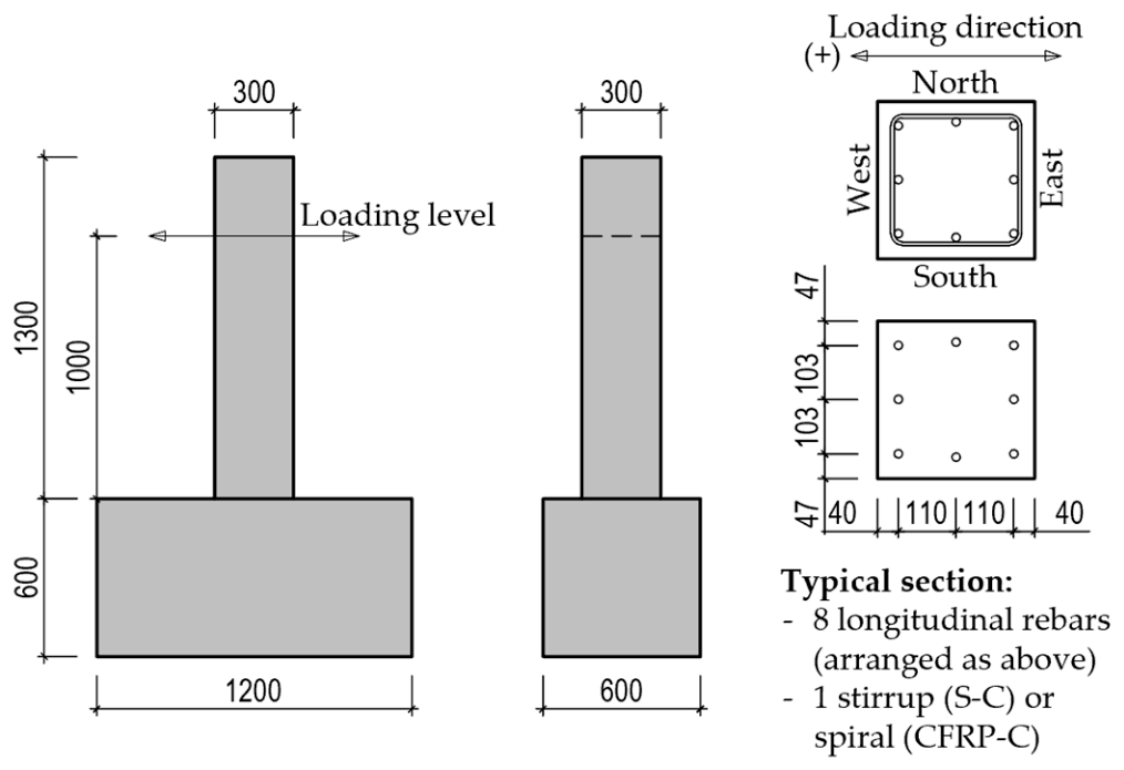
Each column featured a square cross-section measuring 300 × 300 mm and extended 1300 mm above its heavily reinforced footing. The footing dimensions were 1200 × 600 × 600 mm. The shear span, measured as the distance from the base of the column to the lateral loading point’s center, was set at 1000 mm. Each test specimen was reinforced with eight longitudinal main bars positioned along the column perimeter. For transverse reinforcement, steel stirrups were used in SC1-SR, while CFRP spirals were implemented in CFRPC. Figure 1 shows the details of the specimens.
Steel-RC were designed following ACI 318-19 [27], while those reinforced with CFRP adhered to ACI 440.1R-15 [3], both assuming a characteristic concrete strength of 30 MPa. The longitudinal reinforcement was designed so that flexural failure is controlled by concrete crushing, as adopted in previous research [16,20,24,25]. Calculations for theoretical bending moment capacity, using the ultimate stress–strain relationships detailed in the respective standards [3,27] and an axial load ratio of 10% (applied axial load divided by the gross area multiplied by concrete compressive strength), resulted in nearly the same values for both types of columns.
When designing and detailing transverse reinforcement, it is important to consider not only shear capacity but also confinement of the concrete core in seismic-resistant structures [27]. Therefore, to provide equivalent levels of confinement in the two tested columns, in addition to satisfying shear strength requirements, the stirrups in SC1-SR and the spirals in CFRPC were designed so that confinement axial stiffness, Kc, which is as defined by Equation (1), were matched as closely as the available steel and CFRP reinforcement geometries permitted while maintaining the same 75 mm spacing of the transverse reinforcement.
K c = E A v s
where E is the elastic modulus of steel or CFRP, Av is the cross-sectional area of transverse reinforcement, and s is the spiral/stirrup pitch [16]. Steel stirrups for SC1-SR were selected in accordance with ACI 318-19 for seismic-resistant columns [27].
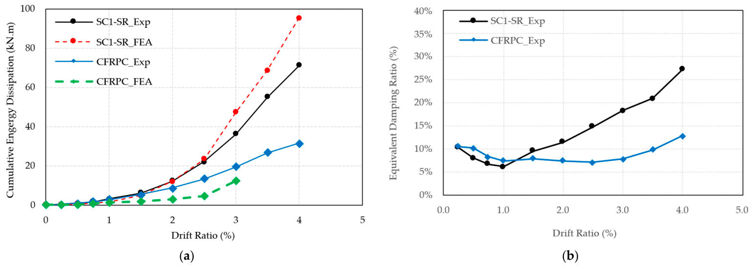
The two additional steel-RC configurations, SC1-NSR and SC2-EA, are introduced for later numerical analysis (quasi-static and dynamic response) based on the following comparative principles. First, a non-seismically designed column with wider stirrup spacing is incorporated, acknowledging that well-confined steel-RC SC1-SR columns demonstrate considerably higher ductility and energy dissipation capacity, approximately twice that of CFRPC at equivalent flexural capacity, as evidenced later in Figure 5a, and that reduced confinement may significantly reduce these benefits (shear capacity is maintained). Second, the steel-RC column SC2-EA with post-cracking stiffness comparable to that of CFRPC is included. This stiffness is governed by the axial stiffness of longitudinal reinforcement Ka, as defined by Equation (2):
K a = E A s
where E is the elastic modulus of steel or CFRP, and As is the cross-sectional area of longitudinal reinforcement. While both columns are expected to exhibit similar post-cracking structural stiffness under lateral bending, after the yielding of steel reinforcement, the stiffness of the steel-RC column degrades notably. Conversely, CFRP maintains its linear stiffness until rupture, resulting in fundamentally different post-yield force-displacement relationships. Although the longitudinal reinforcement area is reduced relative to SC1-SR, SC2-EA retains the same reinforcement detailing and satisfies the requirements of ACI 318-19 [27] for ductile columns in intermediate or special moment frames.
Table 1 summarizes the specimen configurations and theoretical capacities, determined based on a characteristic concrete strength of 30 MPa and an axial load level of 10% (270 kN).

2.1.2. Material Properties

The elastic moduli, Poisson’s ratios, and concrete strengths used for SC1-SR and CFRPC were obtained from testing 100 × 200 mm concrete cylinders on the same loading date and summarized in Table 2. SC1-SR and all footings were reinforced with Japanese SD345 and SD390 steel bars conforming to JIS G 3112 [28]. The mechanical properties of the CFRP straight and bent reinforcement used in the experiment were obtained from tests conducted in the factory in accordance with JSCE-E 531 [29] and JSCE-E 532 [30]. Bent portions, formed with a bend radius-to-diameter ratio of 2.76, had an average of 61% of straight bar tensile strength. Reinforcement properties, including strengths and elastic moduli, are listed in Table 3.

2.2. Loading Program and Hysteretic Results for Validation

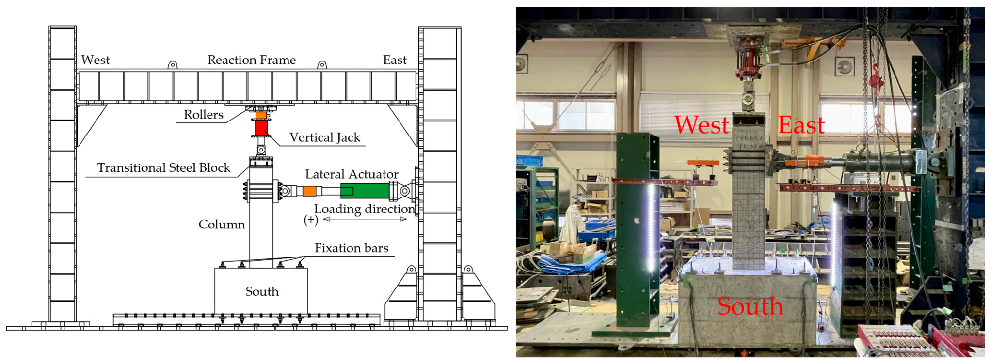
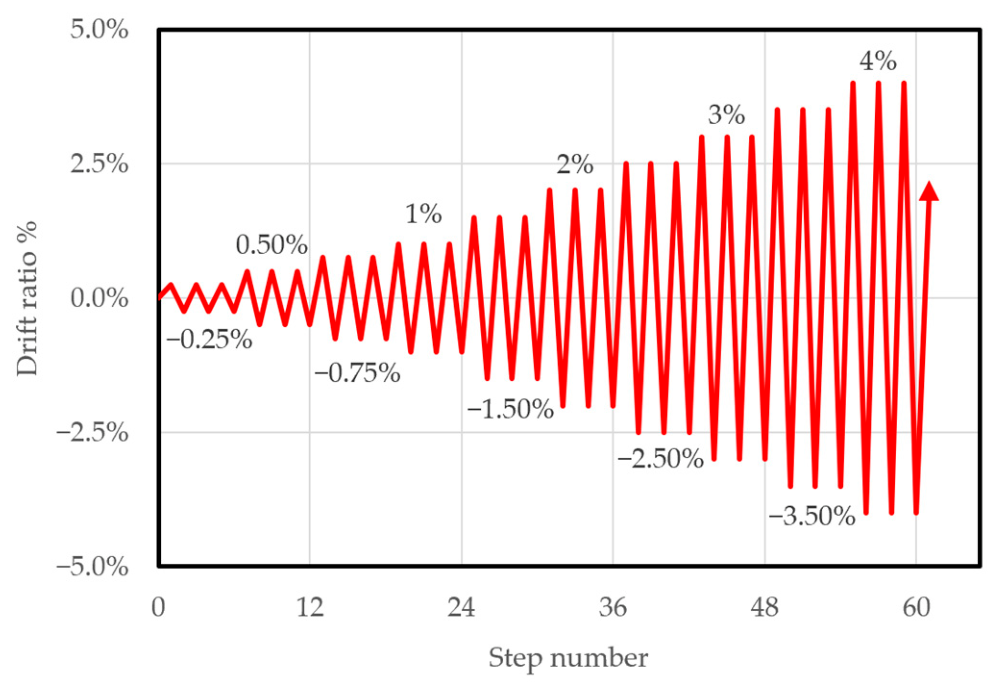
Loading experiments were performed at the Structural Material Laboratory of Saitama University, Japan. Figure 2 illustrates both the schematic and actual test-setup arrangements. The loading program was adapted from the protocol outlined in ACI 374.2R-13 [31]. For each drift level, three loading cycles were applied; drift increments were set at 0.25% for levels under 1% and increased to 0.5% for higher drifts. Details of the loading sequence are presented in Figure 3.
Both columns exhibited flexure-dominated behavior, with failure governed by concrete crushing near the column base. In CFRPC, compressive fractures of the CFRP reinforcement occurred during the first and second positive cycles at 3.5% drift, producing the distinct load drops visible in the hysteretic response during the consecutive negative loading reversal.
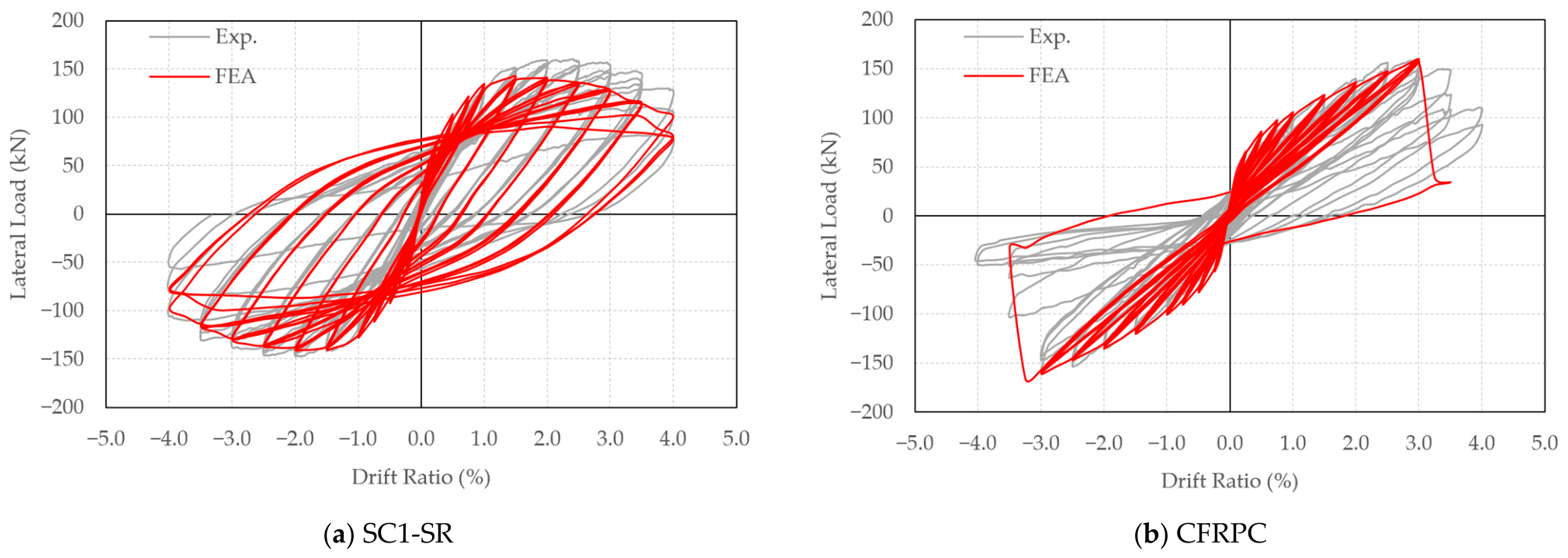
Hysteretic curves, cumulative dissipated energy, and equivalent damping ratio of tested columns are shown in Figure 4 and Figure 5. For the SC1-SR specimen, yielding of the longitudinal reinforcement occurred during the first cycle at a drift level of 1.5% on both sides. The maximum lateral loads reached were 159.8 kN in the positive direction and 147.5 kN in the negative direction, associated with drift ratios of 2.35% and 2%, respectively. Following these peaks, the lateral load declined gradually and then dropped more sharply after each loading cycle at 4% drift. In the CFRPC specimen, the lateral load increased approximately linearly until it reached its peak, with maximum values of 158.5 kN at the 3% drift ratio in both directions. Unlike the SC1-SR column, the reduction in lateral load for CFRPC was primarily due to either concrete deterioration or fractures in the CFRP reinforcement. Noticeable reductions in lateral load, particularly in the negative direction for CFRPC, were observed between the third cycle of 3% drift and the first cycle of 3.5%, as well as in subsequent cycles. These drops correspond well to the previously described compressive fracture events in the CFRP bars.
Energy dissipation during each loading cycle is quantified by the area within its hysteresis loop. The total energy dissipated by all columns is subsequently computed and displayed in Figure 5a. Figure 5b illustrates the equivalent damping ratio, another important parameter affecting the response of structures under earthquakes, plotted as a function of drift ratio. The definition and calculation method of these two parameters can be found in [32]. SC1-SR dissipated roughly double the energy of CFRPC, which is consistent with its broader hysteresis loops resulting from the plastic energy absorption of yielded longitudinal steel bars. Before steel yielded at the 1.5% drift ratio, both columns showed comparable cumulative energy dissipation. However, plastic residual deformation in SC1-SR led to a higher residual drift ratio, defined as the drift at zero lateral load, than in CFRPC. Notably, before reaching 1.5% drift, both columns had nearly the same equivalent damping ratios, each exceeding 5%, which is a typical benchmark for seismic-resistant designs. Beyond 1.5% drift, the damping ratio for SC1-SR increased progressively due to steel reinforcement plasticity. In contrast, from 1.5% to 3% drift, before CFRP fracture, the damping ratio of CFRPC remained around 7%.
Figure 5. (a) Comparison of cumulative energy dissipation. (b) Equivalent damping ratio.
Infrastructures 11 00317 g005

3. Finite Element Modeling and Validation

3.1. Finite Element Model Description and Constitutive Models for Materials

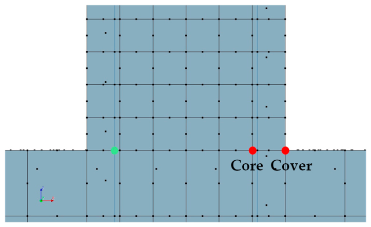
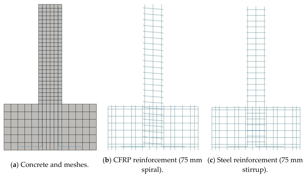
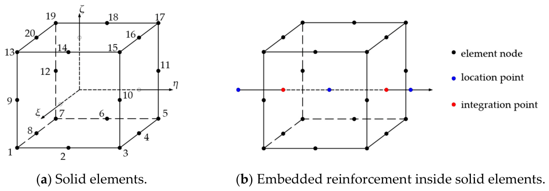
Numerical simulations were performed with DIANA FEA software version 10.8. Figure 6 presents the FE models of both concrete and reinforcement in the DIANA environment. Due to the symmetry of all specimens, only half of each was modeled in three dimensions, employing 20-node solid brick elements. The mesh size was set to 50 mm for column regions and 100 mm for footings. Both steel and CFRP reinforcements were modeled as unidirectional truss elements and treated as embedded reinforcement, presuming a perfect bond with the surrounding concrete.
In a related study, Rabotovao [33] analyzed CFRP-reinforced concrete beams in DIANA, comparing three different bond-slip assumptions between concrete and CFRP bars, including the perfect bond scenario. The outcomes indicated that load-deflection curves were largely consistent across bond-slip models up to beam failure. The perfect bond assumption is therefore considered adequate for the flexure-dominated response examined in this study. It is further supported by the reinforcement used in the experiment, in which both the bars and the spirals featured a deformed surface engineered for bond enhancement. In addition to research on beams under monotonic loading conducted by Rabotovao [33], a comparable treatment has been applied for concrete columns under cyclic loading by Kurihara [34]. Cyclic response of full-scale concrete columns reinforced with deformed BFRP bars has been simulated using a constitutive framework of the same family, without introducing an explicit bond-slip law. The effect of bond-slip under repeated load reversals was nonetheless not investigated in this study, and the perfect-bond assumption is adopted as a simplification on that basis.
Figure 7 depicts examples of the 3D solid elements and the embedded 1D reinforcement.
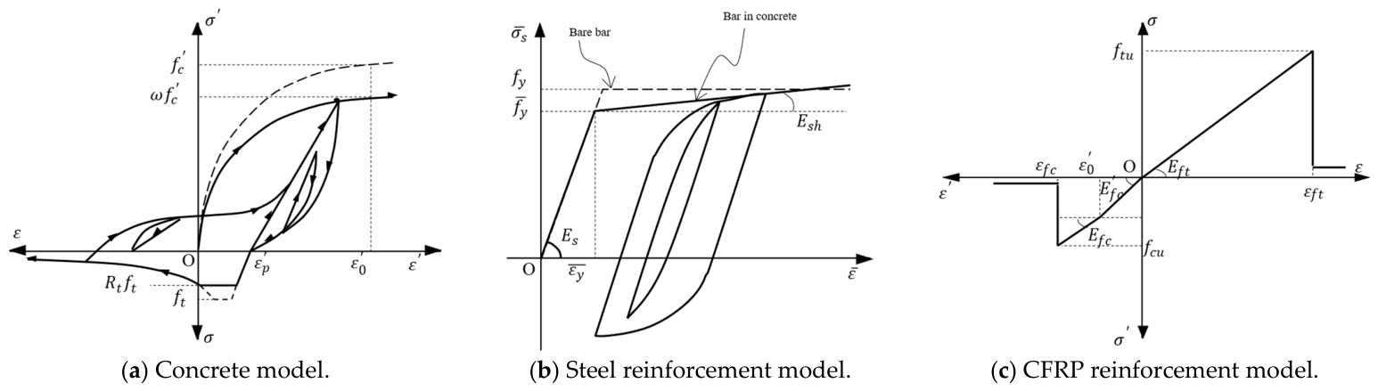
The constitutive models used in this study are shown in Figure 8. For both concrete and reinforcement, we used the widely recognized constitutive laws developed by Okamura and Maekawa [36], which incorporate path-dependent average strain-stress relationships and account for unloading and reloading via the smeared crack approach, as they are integrated into the DIANA software [35]. These models have been validated for simulating cyclic loading in three-dimensional concrete columns reinforced with steel reinforcement [37] and internal FRP reinforcement [34], and have been extensively adopted in Japan, including their inclusion in the JSCE concrete design standards [38]. The applied concrete tension model is tension stiffening, which depends on the bond between the reinforcement and the surrounding concrete, and the stiffening parameter in these models is originally calibrated for deformed steel bars. In the absence of an equivalent calibration for CFRP cable-type bars, the steel value was adopted unchanged for the CFRP-reinforced elements. Kurihara [34] adopted the same treatment for deformed FRP bars when modeling full-scale cyclic column tests. It was also concluded that deformed FRP bars can be modeled using the same approach as steel reinforcement but require consideration of the elastic–rupture behavior and compressive properties [34]. Further details on these constitutive laws can be found in the referenced literature [35,36,38].
Failure in analysis is defined in this study at the level of the constituent materials, as the state at which a material reaches a limit state that causes the structure to lose its load-bearing capacity. A column is considered to have reached a failure state when any of the following criteria are met: (i) the concrete in the compression region at the column–footing interface passes its ultimate compressive strength and the post-peak stress softens to nearly zero, with the core element likewise past peak and softening; (ii) the CFRP reinforcement exceeds its ultimate strain in either tension or compression; or (iii) the steel reinforcement ruptures. The criteria are applied consistently to both loading schemes: the simulation of quasi-static cyclic protocol and the time-history analyses.
In DIANA, CFRP reinforcement, both longitudinal bars and spirals, was modeled using the uniaxial nonlinear elasticity law [35]. Figure 8c illustrates the stress–strain relationship, defined by key stress–strain pairs, and summarized in Table 4. Under tension, the CFRP exhibits a linear stress–strain curve up to its ultimate tensile strain, with parameters derived from the tested material properties in Table 3. For compression, tests were conducted on CFRP bars embedded in concrete cylinders. This testing approach was adapted from Cai [23], and the vertical strain of CFRP reinforcement was to be equal to that of concrete according to Bernoulli’s plane section assumption. Results showed an average compressive elastic modulus of 184.8 GPa ± 12.6% at an average strain of 2520 με ± 4.0%, with the concrete averaging a compressive strength of 56.25 ± 2.2% MPa and modulus of 34.7 GPa ± 4.3%. Beyond 2500 με, which was the average peak compressive strain for the tested concrete, experimental data were limited. Therefore, for strains exceeding this value, the compressive elastic modulus for CFRP was assumed to match the tensile modulus, following Bujotzek’s [39] finding that the moduli in tension and compression are equivalent for bare FRP bars. This assumption was made to cover the lack of data beyond the measured range and does not indicate any physical transition in the material properties. Additional studies by Bujotzek [39] and Zhou [40] indicated that CFRP bars can reach an ultimate compressive strain of 0.6%. The 0.6% value reported by Bujotzek [39] was obtained on bare bar testing with a free length of six bar diameters. In the present columns, the spiral pitch was 75 mm, with a ratio of 3.85 times the longitudinal bar diameter of 19.5 mm. Since the shorter unsupported length provides greater stability under compression, the limit strain value of 6000 με is adopted. On this basis, between 2500 με and 6000 με, the compressive modulus was set equal to the tensile modulus. Bar fracture was represented by reducing the stress to nearly zero once the CFRP strain exceeded its ultimate value in either direction.

3.2. Validation of Finite Element Models

Figure 4 and Table 5 compare the experimental data with numerical simulation results. Overall, FEA closely matched the experimental hysteretic curves. The FEA provided accurate peak load predictions for both columns, with differences of around 10% for SC1-SR and 5% for CFRPC, the latter being slightly overestimated.
For CFRPC columns, experimental and numerical hysteretic curves were evaluated up to a 3.5% drift ratio. The FEA produced narrower hysteretic loops than those observed experimentally, a trend also noted by Zhou [40] in similar analyses. As a result, the simulated energy dissipation was less than that measured in the actual CFRP-RC columns, as shown in Figure 5a. Notably, during the first loading cycle at 3.5% drift for CFRPC, sharp drops in the lateral load-drift response were observed, consistent with both the modeling approach and experimental outcomes. At this stage in the model, compressive stress in the concrete surrounding the CFRP longitudinal reinforcement dropped to nearly zero, shifting compressive force to the CFRP bars. The strain in the CFRP reinforcement then increased rapidly until it reached the assumed ultimate compressive strain of 6000 με, after which the compressive stress in the reinforcement was also reduced to zero, causing the observed drop in the hysteretic curve. Because the post-peak response of CFRP-RC columns is challenging to replicate due to complex material behavior, the abrupt reductions captured in the FEA, although differing from the experimental hysteresis, served as markers that the failure criterion described in Section 3.1 was met in the quasi-static simulation.
For SC1-SR, the experimental and FEA hysteretic curves were nearly identical on the negative side. The FEA simulation reached the peak positive lateral load at a 2% drift, slightly earlier than the 2.35% observed in the experiment. After the peak, the simulated load degradation was more gradual and closely followed the envelope curve, with a noticeable drop occurring at the second cycle of 4%, mirroring the experimental results. However, the FEA did not capture the pinching effect observed at the final drift level in the experiment, resulting in larger hysteretic loops in the simulation and overestimating energy dissipation, as shown in Figure 5a.

3.3. Extended Finite Element Analysis (FEA)

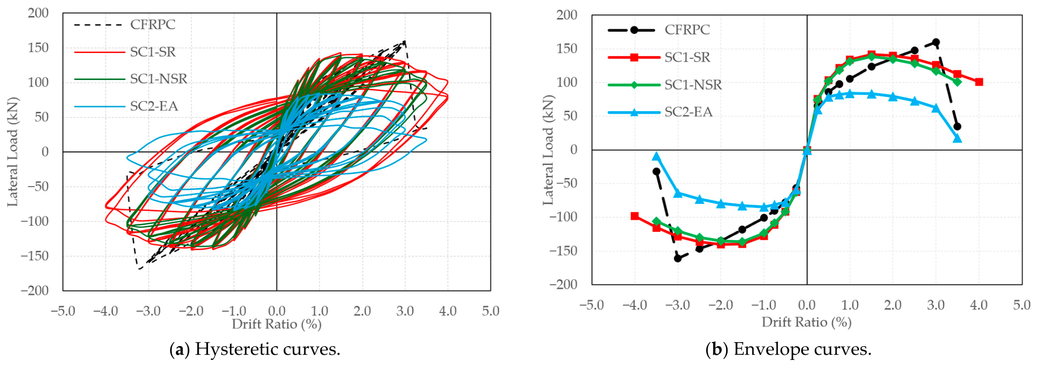
The validated FE models were extended to the two untested configurations, SC1-NSR and SC2-EA, which were simulated under an identical quasi-static cyclic protocol as described in Section 2.2. The design principles of these columns are outlined in Section 2.1. Table 6 summarizes the principal results for all four columns, and Figure 9 provides a comparative analysis of their hysteretic and envelope curves.
SC1-NSR exhibited responses nearly identical to SC1-SR up to the peak load, both yielding at the same 1.5% drift ratio and attaining a marginally lower peak load of 138.5 kN. This similarity can be attributed to the fact that the lateral response before and around the peak is predominantly governed by the longitudinal reinforcement, which is consistent in both columns. The impact of diminished lateral support due to increased stirrup spacing became evident in the post-peak range, where SC1-NSR demonstrated a faster degradation and achieved a drift capacity of 3.5%, in contrast to 4% for SC1-SR. SC2-EA exhibited the earliest yielding at a 0.75% drift and produced the lowest peak load of approximately 84 kN, which is a direct consequence of selecting a smaller longitudinal bar area intended to match the post-cracking stiffness of CFRP-reinforced concrete. Consistent with this design intent, the envelope curves of SC2-EA and CFRPC show nearly identical slopes in the post-cracking range up to the point of steel yielding. Beyond this point, the responses diverge: SC2-EA reaches a plateau with yielding reinforcement, whereas CFRPC continues to gain load in an almost linear fashion, attaining the highest peak among the four columns prior to CFRP compressive fracture at a 3.5% drift.
The four configurations therefore cover the range of behavior intended for the seismic response analysis: a well-confined, high-dissipation steel-RC column (SC1-SR), its reduced-confinement counterpart (SC1-NSR), a stiffness-matched steel-RC column of lower capacity (SC2-EA), and the linear-elastic CFRPC. It should be noted that the results for SC1-NSR and SC2-EA are numerical predictions without direct experimental counterparts; their reliability rests on the validation of the same modeling approach for the two tested columns in Section 3.2. The peak loads in Table 6 define the lateral load capacities used to construct the capacity-derived elastic target spectrum for ground motion selection in Section 4.2.

4. Seismic Response Analysis

4.1. Modeling Principles and Research Objects

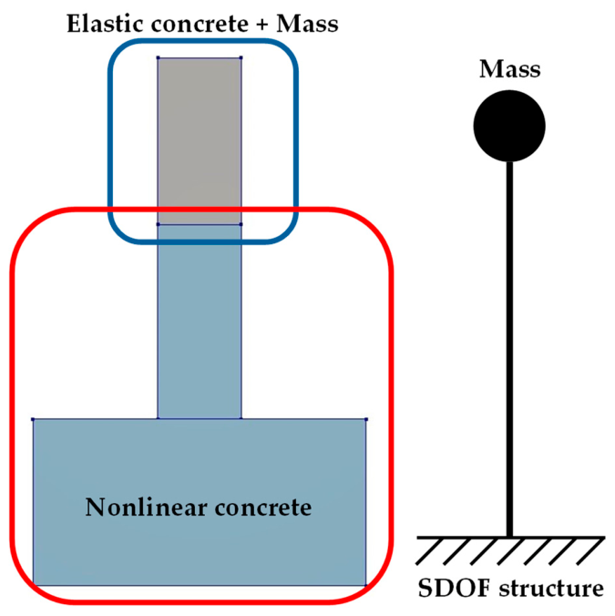
This study uses NLTHA to evaluate seismic response by integrating the equations of motion at each time step, capturing time-dependent hysteretic behavior, energy dissipation, and residual deformation. Response analysis is performed in DIANA FEA, following the validated FE model and constitutive material models described in Section 3. As shown in Figure 10, the analysis focuses on columns and their footings. Each specimen is modeled to demonstrate a single-degree-of-freedom (SDOF) cantilever structure with a concentrated mass at the free end. The column tops are modeled as elastic concrete with mass, fixed at a height of 1000 mm from the column-footing interface to maintain a consistent shear span across this research. Lateral displacement at the concentrated mass, base shear at each time step, final residual drift, and total dissipated energy are extracted for analysis and discussion of each column’s response.

4.2. Selection of Ground Motions

The ground motion suite used in this study is selected against a capacity-derived elastic target spectrum, which is constructed in the opposite direction to normal design practice. In conventional design, an elastic spectrum is obtained from the site hazard and divided by a response modification factor appropriate to the structural system, giving a design-level spectrum against which the required capacity is checked. In this study, the capacity of each column is extracted from the quasi-static simulations of Section 3.3 and is equivalent to the design level of the conventional flow. The elastic target is therefore recovered by multiplying the capacity-based spectral acceleration by the same reduction factor. It is therefore an elastic spectrum, as required for record selection, but derived from member capacity rather than from a site hazard, and it carries no site-specific hazard meaning. The purpose is to characterize how each column responds to near-fault records at a common level, rather than to establish the intensity at which it would fail.
The construction of the target spectrum follows the standard shape of ASCE 7-22 [41], requiring the fundamental elastic period of the structure and a target spectral acceleration anchored to the column’s lateral load capacity. The fundamental elastic period T = 0.15 s is obtained directly from modal analysis in DIANA FEA. The capacity-based spectral acceleration is determined as the ratio of the column’s lateral load capacity to its concentrated mass, representing the spectral demand, as per the following equation:
S c a = F M
where Sca is the capacity-based spectral acceleration, F is peak lateral load, and M is the concentrated mass. The lateral load values for all columns are taken from the FE simulation presented in Section 3.3 and summarized in Table 6.
For steel-RC columns designed and detailed for seismic resistance, SC1-SR and SC2-EA, the elastic spectral demand may be reduced to a design level through the response modification factor R (Reduction factor), as both columns satisfy the detailing requirements of ACI 318-19 [27] for columns in intermediate or special moment frames, as mentioned in Section 2.1. ASCE 7-22 [41] permits the elastic spectral acceleration to be reduced by a factor of 1.5 or 2.5 for intermediate or special concrete moment frame columns acting as vertical cantilevers, and a single value of R = 2 is adopted for both columns. As described above, the procedure operates in the reverse direction, so the capacity-based spectral acceleration of each column is multiplied by its reduction factor to recover the elastic target required for record selection. For the non-seismically detailed column SC1-NSR, no such reduction is applicable, as limited confinement precludes the ductile response that the reduction factor presupposes; its elastic target is taken directly from its capacity. Likewise, for CFRPC, which exhibits linear behavior and is limited to negligible ductility in the experiment, the target is taken directly from its capacity. Each of the four assignments therefore follows from detailing and material behavior: R = 2 where ductile response is available, and R = 1 where it is not. The concentrated mass is taken as 27 tons for all columns, consistent with the axial load of 270 kN applied in the quasi-static loading test. Table 7 summarizes the required elastic target spectral acceleration S e a for each column.
Per ASCE 7-22 [41], the mean spectrum of the scaled ground motion suite is required to match the target spectrum over the period range [0.2T, 2.0T]. However, because the research object is an SDOF structure, the lower bound of this range is not governed by higher-mode contributions. Enforcing spectral matching down to this lower bound is therefore unnecessary and practically problematic, as very few recorded ground motions possess spectral shapes compatible with the target at such short periods. Accordingly, the matching range is extended in this study to [0.5T, 2.5T], corresponding to [0.075 s, 0.375 s].
The upper bound of 2.5T is physically motivated by the period elongation experienced by the column under inelastic seismic response. As lateral stiffness degrades under repeated cyclic loading, the column’s effective period lengthens progressively. The residual lateral stiffness of the columns ranges between approximately 20% and 70% of the initial elastic stiffness [42], corresponding to effective period elongation factors of up to 2.2T. Extending the matching range thus ensures that the ground motion suite remains spectrally representative of the column’s dynamic characteristics throughout the full range of its inelastic response, from initial yielding through to near-collapse conditions.
Among the four column configurations, CFRPC serves as the main research object, while three steel-RC specimens serve as references; therefore, CFRPC is the anchor for the capacity-derived elastic target spectrum. As summarized in Table 7, the elastic target spectral accelerations of three of the four columns, CFRPC, SC1-NSR, and SC2-EA, are comparable. SC1-SR is the exception, exhibiting a notably higher target value because of its greater flexural capacity combined with the seismic reduction factor. The reduction factor is what brings SC2-EA into the common range: its capacity-based value of 0.32 g is the lowest of the four, but the ductile detailing that permits R = 2 raises its elastic target to 0.64 g. A single suite matched to the CFRPC anchor is therefore spectrally representative for three of the four columns; SC1-SR is subjected to a demand below its own elastic target, and its response is accordingly compared at the common intensity rather than at its individual design level.
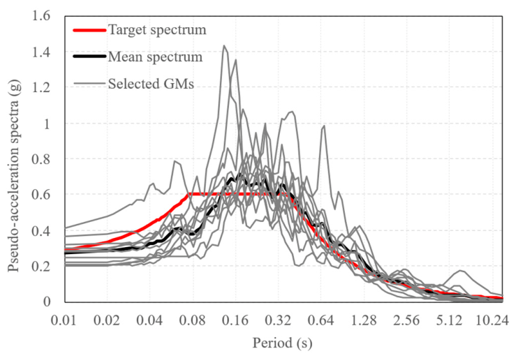
The selection of ground motions follows the provisions of ASCE 7-22 [41], with all records obtained from the PEER NGA-West2 strong motion database [26]. The code requires a suite of not less than 11 ground motions. 11 selected records are near-fault ground motions with relatively short duration, less than 20 s. This selection is consistent with the properties of the structure under investigation. With a fundamental period of T=0.15 s, the columns are short-period, stiff structures whose response is governed by high-frequency and sensitivity to acceleration, which are characteristics of near-fault motions. Basic information on selected ground motions is shown in Table 8, and detailed acceleration records over time are shown in Figure A1. Figure 11 compares the target spectrum and the mean spectrum of 11 selected ground motions.

4.3. Results of Response Analysis and Discussion

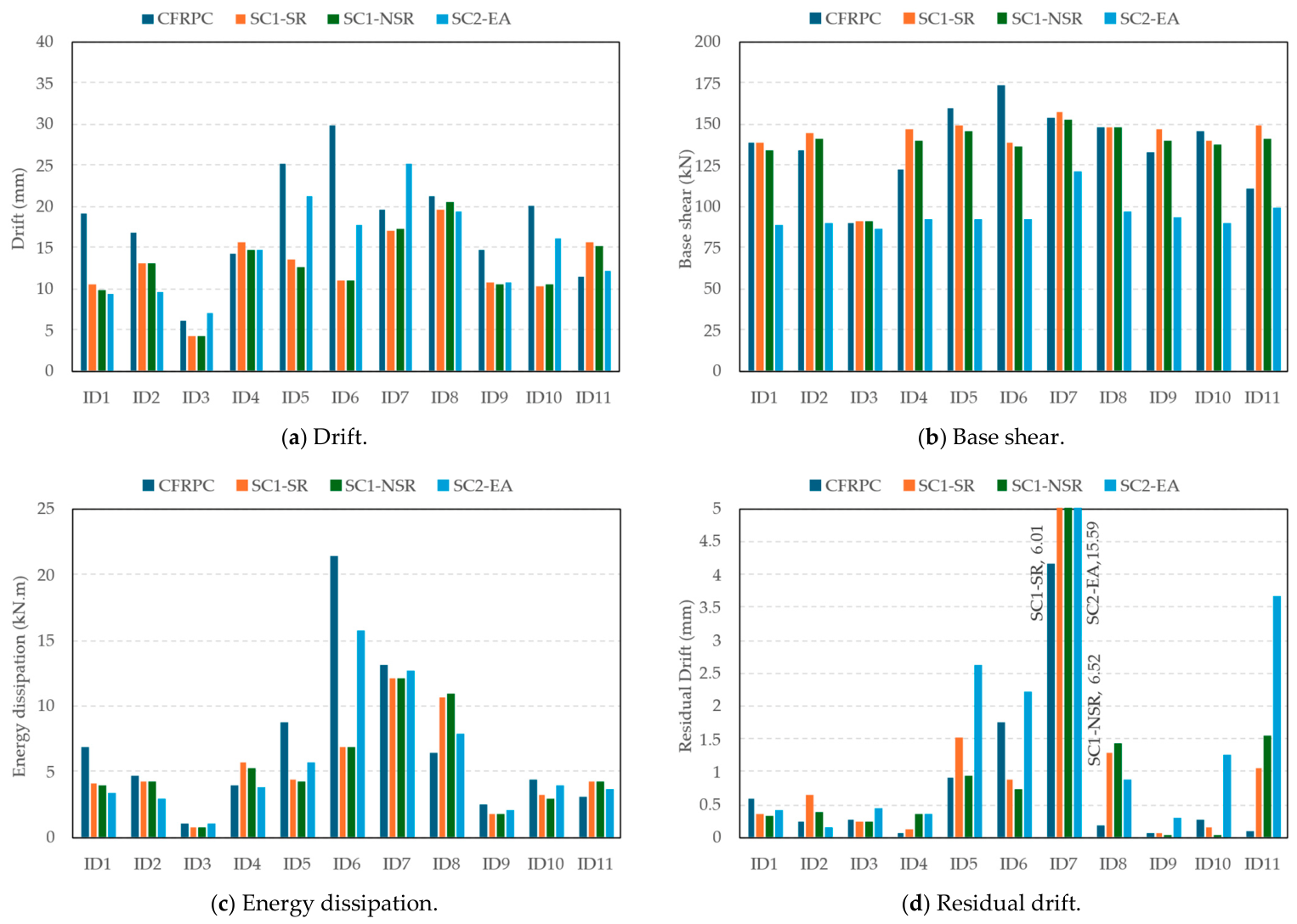
Table 9 and Figure 12 present the analysis results for columns under all 11 ground motions. None of the four columns reached a failure state across the entire suite of ground motions, as defined in Section 3.1, even though their peak base shear, equivalent to the acting lateral force at the concentrated mass, exceeded the nominal lateral load capacity used to construct the target spectrum. Because the criterion is stated at the level of the constituent materials, the relevant evidence is the strain reached in each material rather than the load carried. No concrete element in any column softened to nearly zero stress, no steel reinforcement ruptured, and the CFRP reinforcement did not exceed its ultimate strain in either direction. The strains reported here are maximum values over all CFRP reinforcement elements throughout the full duration of each record. The margin against the governing limit was nonetheless narrow. The peak compressive strain in the CFRP reinforcement reached 5634 με under record ID6, or 93.9% of the ultimate value of 6000 με. Peak tensile strain, by contrast, reached approximately 7150 με also under ID6, about 47.6% of the tensile limit. Since quasi-static and dynamic loading differ, exceeding the nominal lateral capacity obtained from quasi-static simulation indicates a post-elastic response rather than failure. The suite therefore imposed a demand that approached, but did not reach, the material failure criterion under the selected records. A further distinction appears in the base shear responses shown in Figure 12: the mean peak base shears of the three steel-RC columns were similar to their respective lateral load capacities, whereas CFRPC showed considerably larger record-to-record variation. CFRPC remains linear elastic after cracking, so its base shear grows in proportion to the displacement each record produces; as a result, the variability of the ground motions transfers directly into its force response.
Overall, CFRPC experienced larger displacements than the steel-RC columns. This behavior is attributed to its limited energy-dissipating capability and an equivalent damping ratio of only approximately 7%, as the reinforcement remains linear-elastic and thus dissipates seismic input energy inefficiently through hysteretic action. CFRPC accommodates earthquake-induced demands primarily through increased displacement amplitudes, resulting in the largest drift among the four columns. However, CFRPC exhibited the smallest residual displacement, consistent with the low residual drift observed experimentally and attributed to the linear-elastic recovery of the CFRP reinforcement up to failure.
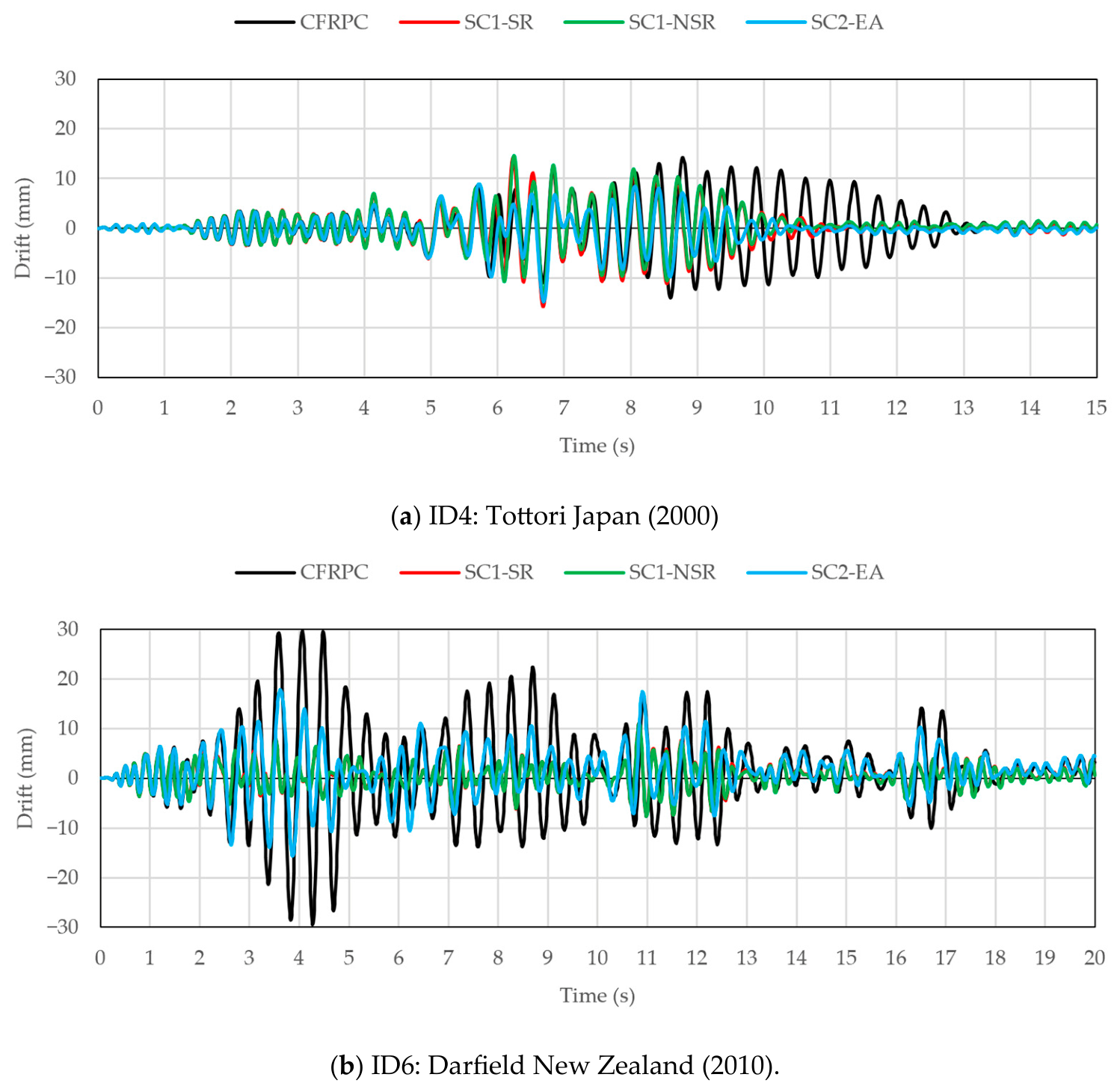
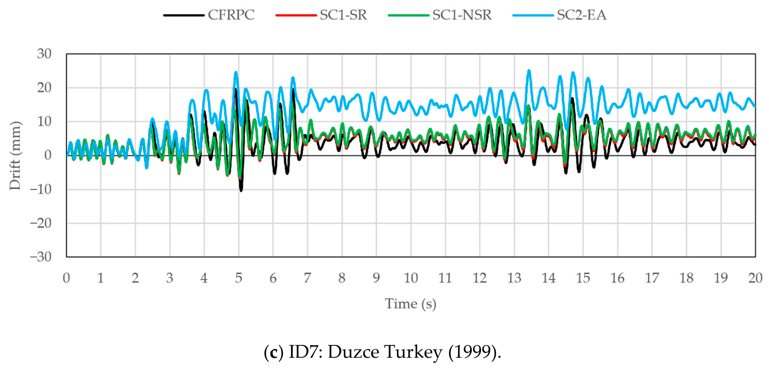
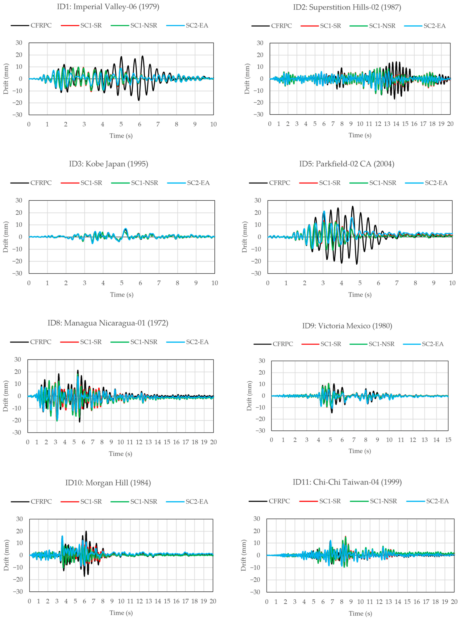
Response histories of the columns are shown in Figure 13 and Figure A2. It can be observed that the post-cracking stiffness of the columns influenced the number of cycles they experienced. CFRPC and SC2-EA had lower post-elastic stiffness, resulting in longer vibration periods and lower frequencies than SC1-SR and SC1-NSR. Moreover, the post-cracking stiffness of the steel-RC columns depends on whether the steel reinforcement has yielded: while the reinforcement remains elastic, the columns retain higher stiffness and therefore a shorter vibration period, whereas yielding further reduces stiffness and lengthens the period. As a result, their responses, initially in phase during the early elastic stage, gradually drifted out of phase as the analysis progressed, with peaks and reversals no longer coinciding toward the end of the records (clearly observed in the response histories of ID5 in Figure A2). Representative responses obtained from three ground motion records (in Figure 13), namely ID4, ID6, and ID7, were selected for analysis and comparison of column responses, based on their distinct effects on column behavior.
The input earthquake ID4 consisted of a compact, symmetric energy burst concentrated between 4 and 8 s. All four columns responded predominantly in phase, exhibiting similar amplitudes of 10–15 mm during the strong shaking. Distinctions in response became apparent only after the burst subsided from the 8th second. The three steel-RC columns’ displacement decreased within the following two to three cycles due to hysteretic energy dissipation. In contrast, CFRPC continued oscillating at large amplitude for an additional four seconds before its decayed response could be clearly observed. The symmetric burst prevented permanent offsets, resulting in all columns returning to near the origin. Similar behavior was observed under ID1, ID2, ID5, ID8, and ID10, indicating that this prolonged-decay pattern was the most common response across the suite.
ID6 subjected the columns to sustained, wide-ranging shaking of moderate amplitude over nearly 17 s, rather than a concentrated burst. During this prolonged excitation, CFRPC experienced the largest displacement of the entire suite, reaching 30 mm, approximately twice that of the steel-RC columns. This earthquake induced a drift of 86% of the 35 mm drift capacity established in the quasi-static simulation, and to 93.9% of the ultimate compressive strain of the CFRP reinforcement. Because CFRPC dissipates little energy, has low damping, and lacks a plastic hysteretic mechanism, its response accumulates over successive cycles rather than decaying. In contrast, the steel columns benefited from both per-cycle hysteretic dissipation and period elongation due to yielding.
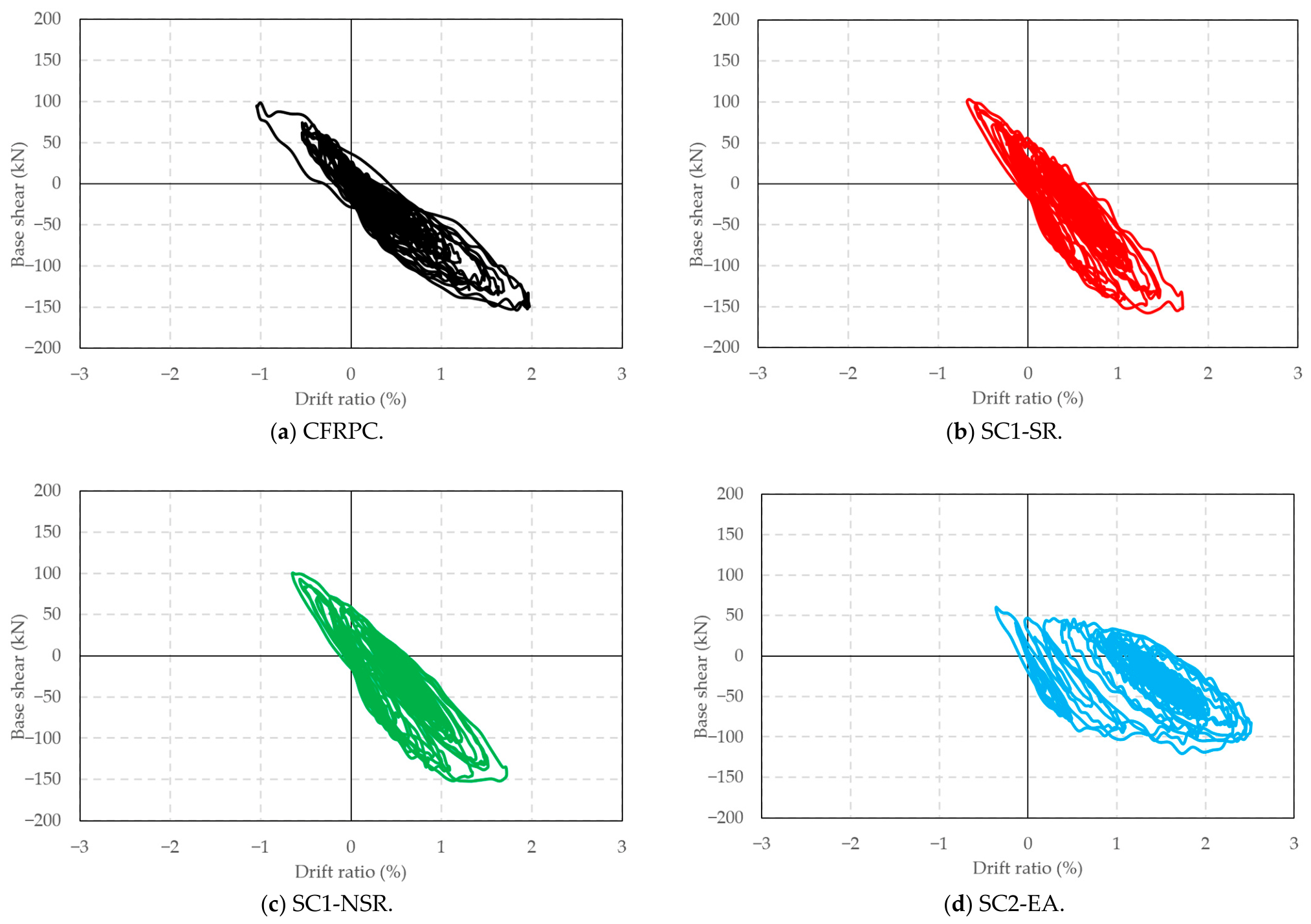
Columns under ID7 imposed the most severe inelastic behavior within the suite for the steel-RC columns, as their residual deformations were largest under this record. Hysteretic curves of all four columns are shown in Figure 14. The input consisted of strong, directionally biased pulses during the early phase (approximately 2–7 s), followed by sustained shaking and a secondary burst at 13–15 s. All four columns responded similarly until the steel reinforcement yielded. From about the sixth second onward, the steel-RC columns progressively shifted away from the origin, as each one-sided plastic excursion left a permanent residual deformation that was compounded by successive same-direction pulses. The magnitude of residual drift was inversely related to reinforcement content: SC1-SR and SC1-NSR stabilized at 6 mm and 6.5 mm of residual drift, respectively, while SC2-EA, which yielded earliest, ended at 15.6 mm. CFRPC, whose reinforcement unloaded elastically after each excursion, oscillated about its initial position throughout and concluded with a smaller residual displacement of 4 mm.
Collectively, the four records show that the relative performance of the two reinforcement systems depends on the energy-delivery characteristics of the ground motion, including concentration, symmetry, and duration. The steel-RC columns consistently limit transient displacement through hysteretic damping and period detuning, but this results in a final position that is sensitive to the directional bias of the input. In contrast, CFRPC exhibits larger and more prolonged transient displacement, especially under sustained wide-range shaking, in exchange for near-complete elastic re-centering and consistently low residual drift across all records.
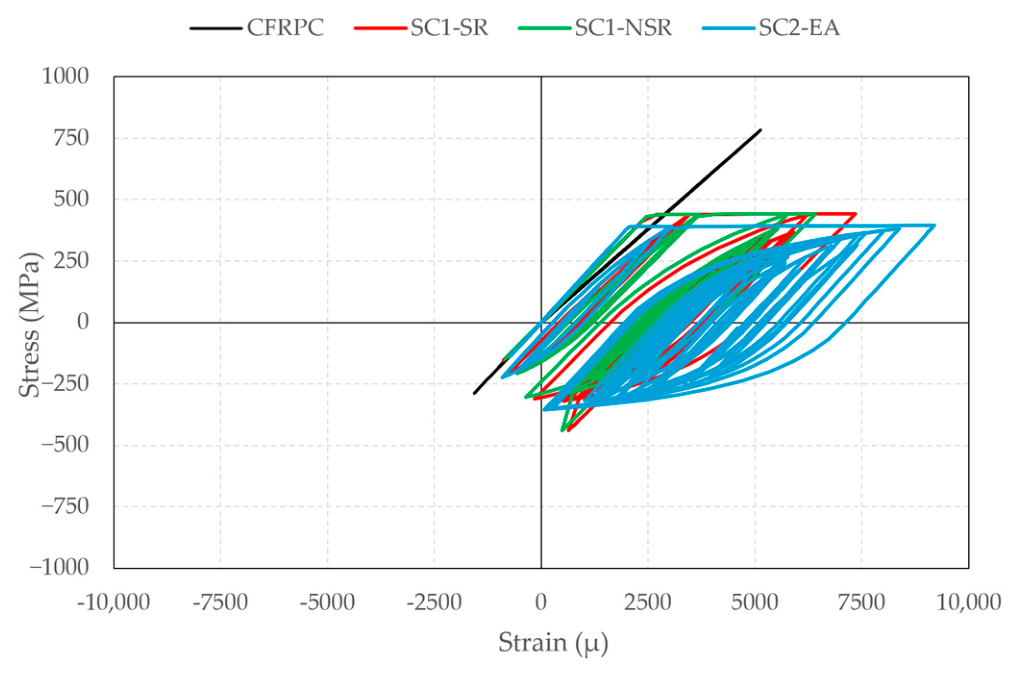
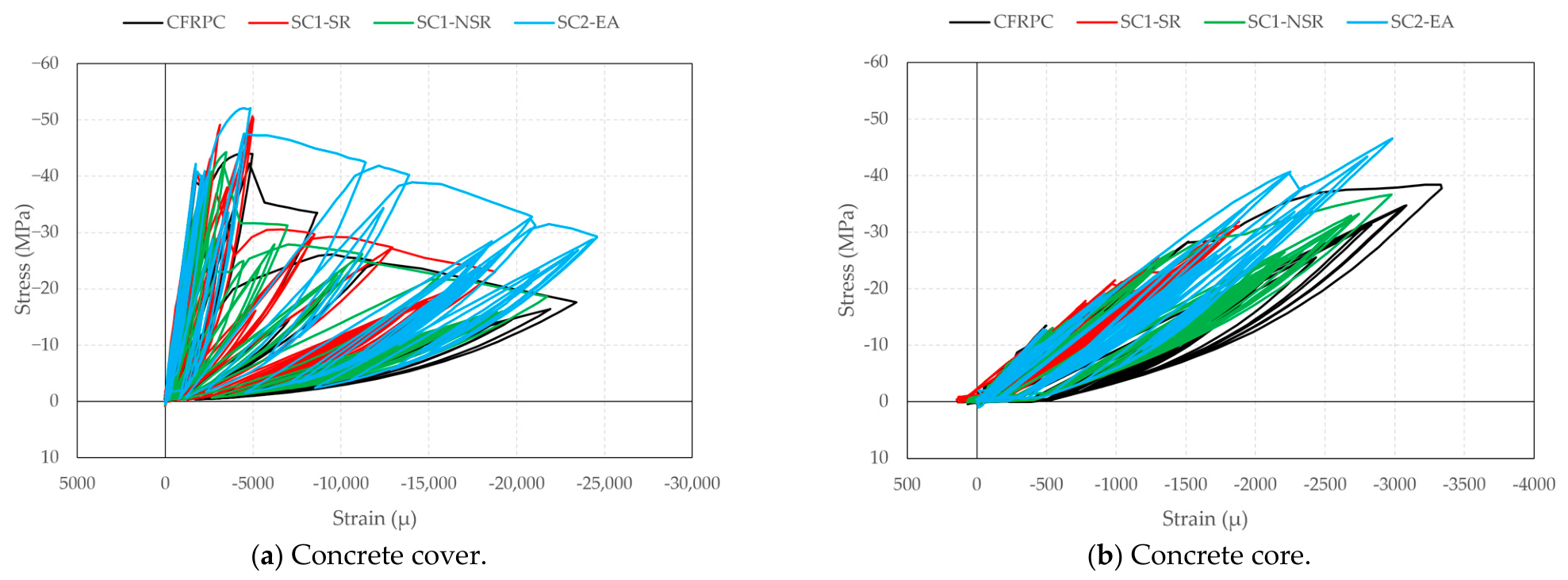
Besides the global response and hysteretic relationship between load and drift, the material-level response of the columns under earthquake ID 7 is analyzed in detail, since, as aforementioned, columns subjected to ID7 showed the most severe inelastic behavior. The selected nodes for extracting material behavior and extracted stress–strain relation curves are shown in Figure 15, Figure 16 and Figure 17. The CFRP reinforcement traced a single linear path in both tension and compression, loading and unloading along the same line with no residual strain, and reached a peak tensile stress of approximately 780 MPa (about 34% of its ultimate strength). By contrast, the steel bars in the three SC columns reached yield and developed wide hysteretic loops with progressively accumulating tensile strain, corresponding to the global progressive accumulation: residual strains of approximately 3500 µε in SC1-SR and SC1-NSR, and around 5000 µε in SC2-EA. The concrete response reflected the equilibrium consequences of the two reinforcement systems.
All columns developed extensive plastic straining in the cover and softened to residual stresses of approximately 15–30 MPa. None of the covers softened toward zero stress, indicating that even at the most damaged fiber, the concrete retained meaningful load-carrying capacity, and no column reached a failure state. Among the four, the cover of SC2-EA softened the least, retaining roughly 30 MPa at strains beyond 20,000 με. This is attributed to its predominantly one-sided response: because the column accumulated deformation in one direction, its cover concrete experienced far fewer reversals between compression and tension than the other columns. In the Maekawa elasto-plastic fracture model, damage accumulates with each unloading–reloading excursion, so the reduced number of reversals resulted in less cyclic degradation of the compressive response.
The concrete core conditions across the columns were generally similar, except for the well-confined steel-RC column SC1-SR. In the CFRP-RC column, since the CFRP did not yield and behaved elastically, the section continued to attract force as deformation increased, driving the concrete core compression zone of CFRPC to the largest compressive strain of the four columns, approximately 3300 µε at a peak stress of about 38 MPa. SC2-EA achieved a comparable level of concrete core damage, with a peak stress of nearly 46 MPa, through a different mechanism: compression concentrated on one face of the section as the column shifted toward its offset position. For SC1-NSR, although its global response was nearly identical to that of SC1-SR, the core strain excursions were similar to those observed in CFRPC. Well-confined concrete typically demonstrates both higher peak stress and greater corresponding strain [32], so with only half the confinement stiffness, the core concrete of SC1-NSR followed a softer stress–strain envelope and entered plastic behavior earlier than SC1-SR under equivalent displacement demand. The three columns, CFRPC, SC2-EA, and SC1-NSR, thus attained similar concrete stress–strain relationships via distinct mechanisms: elastic symmetric excursions in CFRPC, one-sided concentrated plastic accumulation in SC2-EA, and reduced confinement-induced softening in SC1-NSR. Only SC1-SR maintained visibly lower stress and strain levels, combining effective hysteretic energy dissipation with a well-confined concrete core. In all four columns, concrete stresses remained within the post-peak softening range, consistent with the absence of crushing failure under any loading record in the suite.

5. Conclusions

In this paper, the seismic response of a CFRP-RC column and three steel-RC columns was investigated by FE simulations under quasi-static loading and dynamic loading conditions. The following conclusions could be drawn:
  • From experimental results, the CFRP-RC column and the steel-RC column with equivalent confinement stiffness and similar lateral load capacity had a 50% difference in favor of the column reinforced with conventional steel. The cumulative energy dissipation of the tested CFRP-RC column was approximately 50% of that of the reference steel-RC column with equivalent confinement stiffness and similar lateral load capacity. FE simulation agreed well with the experiments, though it had limitations in capturing the pinching effect of the steel-RC column and underestimated the energy dissipation capability of the CFRP-RC column.
  • Under a suite of 11 near-fault ground motions, with mean spectra matching the capacity-derived elastic target spectra of three of the four columns, none of the columns reached a failure state. Although peak base shears exceeded the nominal lateral capacities determined from quasi-static simulation, they indicated inelastic response rather than failure, as no deformation or material strain limit, such as concrete crushing, reinforcement rupture, or excessive drift, was reached under any record. The margin was nevertheless narrow and is quantified rather than assumed: under the governing record, the CFRP reinforcement reached 93.9% of its ultimate compressive strain, and the column reached 86% of its quasi-static drift capacity. The suite therefore imposed a demand approaching the material limit of the CFRP-RC column, while remaining bounded by an intensity anchored to column capacity rather than to any hazard level. In contrast to the steel-RC columns, whose peak base shears were limited by reinforcement yielding, the column reinforced with CFRP experienced lateral loads that varied across records. This variation is consistent with CFRPC’s post-cracking linear-elastic behavior, where the load is proportional to the displacement imposed by each earthquake. These contrasting responses underscore the importance of distinguishing capacity exceedance from failure when evaluating near-fault column performance;
  • The two reinforcement systems demonstrated a distinct trade-off. CFRPC exhibited the largest transient drift because its linear-elastic reinforcement and an equivalent damping ratio of approximately 7% do not provide a hysteretic mechanism for dissipating input energy, but it achieved relatively small residual drift under all records through the elastic recovery of the CFRP reinforcement. In contrast, the steel-RC columns limited transient amplitudes through hysteretic dissipation but accumulated permanent offsets under directionally biased input, most notably in SC2-EA. Consequently, the relative performance of these systems depends on the energy delivery characteristics of the ground motion, including concentration, symmetry, and duration;
  • The response histories demonstrated the dynamic effects of the columns’ differing stiffness and energy dissipation properties. The columns with lower and comparable post-cracking stiffness, CFRPC and SC2-EA, possessed longer vibration periods and experienced fewer response cycles compared to others. Initially, in-phase responses gradually became out of phase over the course of the records. Due to the absence of hysteretic dissipation, the CFRP-RC column accumulated response over successive cycles rather than exhibiting decay. It reached the largest displacement of the suite under sustained wide-range shaking and continued oscillating for several seconds after strong shaking stopped, whereas the steel-RC columns settled much faster within two to three cycles. At the material level, except for the well-confined steel-RC column, the other three columns reached similar concrete damage states.
The narrow margin observed at the material level leads to engineering design recommendations by the authors. Under a suite of ground motions matched to the CFRP-RC column’s own capacity, the largest recorded compressive strain of the CFRP reinforcement reached 93.9% of its limit, leaving a margin of only approximately 6%. Exceeding the strain limit of CFRP may produce an abrupt loss of load-bearing capacity accompanied by large deformation, and a margin of this size is therefore relatively small for a design condition. Two measures are recommended, acting at different levels. At the material level, apply a safety reduction coefficient to the ultimate strain of the CFRP reinforcement in both tension and compression. At the system level, CFRP-RC columns should be designed for a capacity greater than that required by the code target spectrum, with the appropriate overdesign coefficient established through further study. Parametric investigation of reinforcement ratio, sectional geometry, axial load level, and structural system is also recommended.

Author Contributions

Conceptualization, M.Q.V.; methodology, M.Q.V.; software, M.Q.V.; validation, M.Q.V. and T.M.; formal analysis, M.Q.V.; investigation, M.Q.V.; resources, T.M.; data curation, M.Q.V.; writing—original draft preparation, M.Q.V.; writing—review and editing, M.Q.V. and T.M.; visualization, M.Q.V. and T.M.; supervision, T.M.; project administration, T.M. All authors have read and agreed to the published version of the manuscript.

Funding

This research received no external funding.

Data Availability Statement

Data are available from the corresponding author upon reasonable request.

Acknowledgments

The authors gratefully acknowledge the support of Saitama University, especially the members of the Structural Material Laboratory. The contribution of Ousuke Yoshida and Vu-Minh-Kha Phan, two graduates, and Fuka Suzuki, a master’s student of the Structural Material Laboratory, to the experimental work is deeply appreciated. The authors also express sincere gratitude to Tokyo Rope International Inc. for providing the CFRP reinforcement used in this research.

Conflicts of Interest

The authors declare no conflicts of interest.

Appendix A

Appendix A.1. Acceleration History Record of Ground Motions

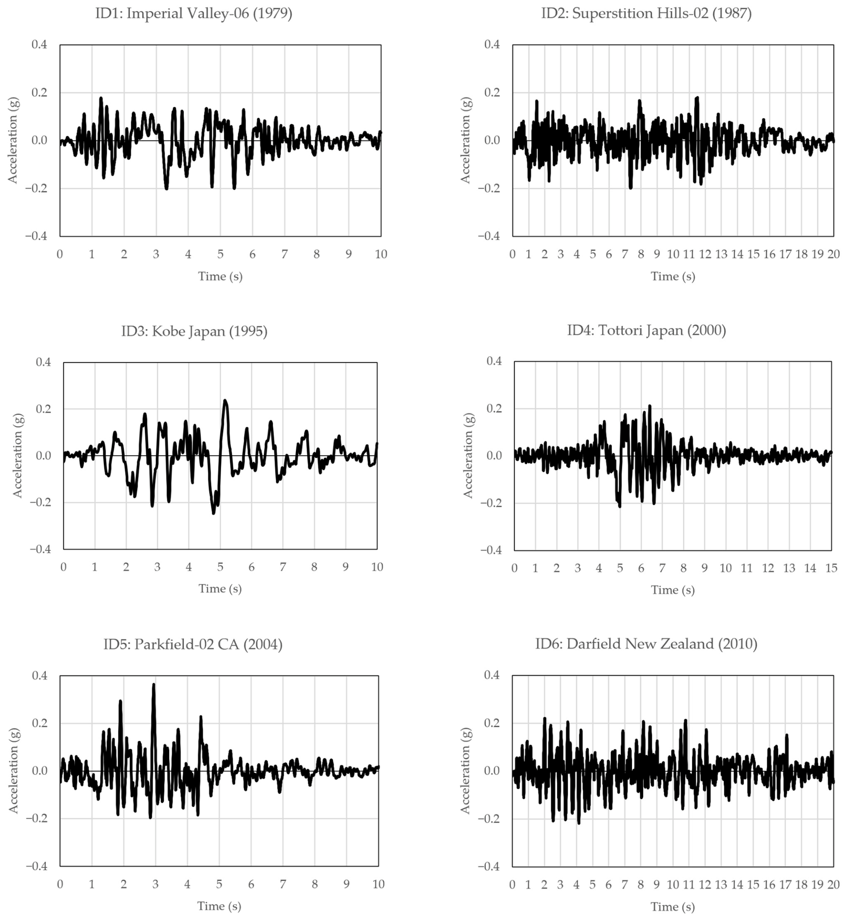
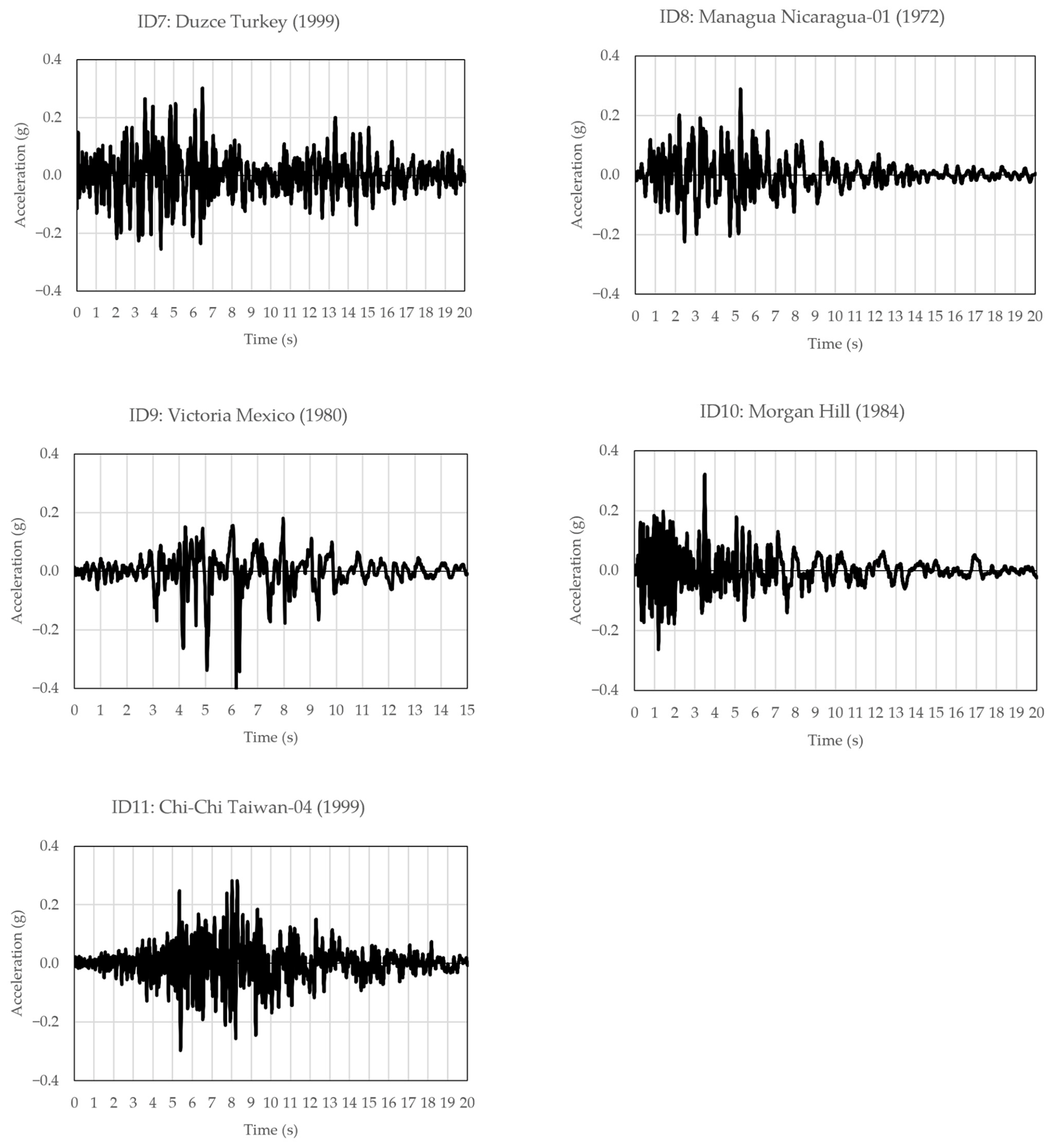
This Appendix presents the acceleration time histories of the 11 selected ground motions, scaled by the factors listed in Table 8.
Figure A1. Acceleration history record of ground motions.
Infrastructures 11 00317 g0a1aInfrastructures 11 00317 g0a1b

Appendix A.2. Drift Response History of Columns Under Remaining Ground Motions

This Appendix presents the drift response histories of the four columns under the ground motions not featured in Section 4.3, including ID1, ID2, ID3, ID5, ID8, ID9, ID10, and ID11.
Figure A2. Drift response history of columns under remaining ground motions.
Infrastructures 11 00317 g0a2

References

  1. Nanni, A.; De Luca, A.; Zadeh, H.J. Reinforced Concrete with FRP Bars: Mechanics and Design; CRC Press: Boca Raton, FL, USA, 2014. [Google Scholar]
  2. Sasaki, K.; Inoue, N.; Anzai, A.; Ishikawa, H.; Ushijima, K.; Enomoto, T. Structural Behavior of Concrete Beams Using CFRP Strands Instead of Steel Rebars. In Proceedings of the 12th International Conference on FRP Composites in Civil Engineering (CICE 2025); João, R.C., Cabral-Fonseca, S., Gonilha, J., Firmo, J., Garrido, M., Eds.; Springer Nature: Cham, Switzerland, 2026; pp. 857–868. [Google Scholar]
  3. American Concrete Institute. Guide for the Design and Construction of Structural Concrete Reinforced with Fiber-Reinforced Polymer (FRP) Bars; American Concrete Institute: Farmington Hills, MI, USA, 2015. [Google Scholar]
  4. American Concrete Institute. Building Code Requirements for Structural Concrete Reinforced with Glass Fiber-Reinforced Polymer (GFRP) Bars: Code and Commentary; American Concrete Institute: Farmington Hills, MI, USA, 2022. [Google Scholar]
  5. Canadian Standards Association. Design and Construction of Building Components with Fibre-Reinforced Polymers; Canadian Standards Association: Mississauga, ON, USA, 2012. [Google Scholar]
  6. Japan Society of Civil Engineers. Recommendation for Design and Construction of Concrete Structures Using Continuous Fiber Reinforced Materials; Japan Society of Civil Engineers: Tokyo, Japan, 2007. [Google Scholar]
  7. Japan Prestressed Concrete Institute. Recommendation for Design and Construction of Concrete Structures Using Fiber Reinforced Polymer (FRP); Japan Prestressed Concrete Institute: Tokyo, Japan, 2021. [Google Scholar]
  8. Elmessalami, N.; El Refai, A.; Abed, F. Fiber-Reinforced Polymers Bars for Compression Reinforcement: A Promising Alternative to Steel Bars. Constr. Build. Mater. 2019, 209, 725–737. [Google Scholar] [CrossRef] [Scilit]
  9. Hamid, F.L.; Yousif, A.R. Comprehensive Review of FRP Reinforced Concrete Columns: Behavior, Design Challenges, and Performance Insights. Struct. Concr. 2025, 27, 3944–3966. [Google Scholar] [CrossRef] [Scilit]
  10. Afifi, M.Z.; Mohamed, H.M.; Benmokrane, B. Strength and Axial Behavior of Circular Concrete Columns Reinforced with CFRP Bars and Spirals. J. Compos. Constr. 2014, 18, 04013035. [Google Scholar] [CrossRef] [Scilit]
  11. Mohamed, H.M.; Afifi, M.Z.; Benmokrane, B. Performance Evaluation of Concrete Columns Reinforced Longitudinally with FRP Bars and Confined with FRP Hoops and Spirals under Axial Load. J. Bridge Eng. 2014, 19, 04014020. [Google Scholar] [CrossRef] [Scilit]
  12. Hadhood, A.; Mohamed, H.M.; Benmokrane, B. Axial Load–Moment Interaction Diagram of Circular Concrete Columns Reinforced with CFRP Bars and Spirals: Experimental and Theoretical Investigations. J. Compos. Constr. 2017, 21, 04016092. [Google Scholar] [CrossRef] [Scilit]
  13. Zhu, F.; Zhang, M.; Zhang, D.; Wang, D.; Wang, Z.; Zhang, Y. Seismic Behavior of FRP-Retrofitted Rectangular RC Columns Subjected to Oblique Horizontal Earthquake Actions. Constr. Build. Mater. 2025, 482, 141737. [Google Scholar] [CrossRef] [Scilit]
  14. Lu, D.; Wang, X.; Sun, Z.; Ding, L.; Ding, J.; Liu, J.; Chen, Z.; Wu, Z. Seismic Design of FRP Grid and Bar Strengthened RC Columns via Multi-Objective Optimization and Decision Analysis. Constr. Build. Mater. 2026, 519, 145826. [Google Scholar] [CrossRef] [Scilit]
  15. Kim, J.H.; Kim, Y.J.; Wang, J. Seismic-Fire-Combined Loadings Applied to Carbon Fiber-Reinforced Polymer-Confined Reinforced Concrete Columns. ACI Struct. J. 2023, 120, 169–184. [Google Scholar] [CrossRef] [Scilit]
  16. Souza, W.M.; Correia, J.R.; Firmo, J.P.; Almeida, J.; Rosa, I.C.; Correia, A.A. Experimental Study on Seismic Behavior of Concrete Columns Reinforced with Glass Fiber-Reinforced Polymer Bars. ACI Struct. J. 2024, 121, 131–148. [Google Scholar] [CrossRef] [Scilit]
  17. Elshamandy, M.G.; Farghaly, A.S.; Benmokrane, B. Experimental Behavior of Glass Fiber-Reinforced Polymer-Reinforced Concrete Columns under Lateral Cyclic Load. ACI Struct. J. 2018, 115, 337–349. [Google Scholar] [CrossRef] [Scilit]
  18. Ali, M.A.; El-Salakawy, E. Seismic Performance of GFRP-Reinforced Concrete Rectangular Columns. J. Compos. Constr. 2016, 20, 04015074. [Google Scholar] [CrossRef] [Scilit]
  19. Noroozolyaee, M.; Mostofinejad, D.; Saljoughian, A.; Zamanvaziri, A. Behavior of Square Concrete Column Reinforced with GFRP Bars under Reversed Cyclic Eccentric Loading: Experimental and Analytical Study. Case Stud. Constr. Mater. 2025, 23, e05598. [Google Scholar] [CrossRef] [Scilit]
  20. Liu, C.; Zhou, Y.; Lu, Y.; Qi, L. Experimental Seismic Performance of Carbon FRP-reinforced Concrete Columns: Experimental Evaluation. Struct. Concr. 2025, 26, 6800–6815. [Google Scholar] [CrossRef] [Scilit]
  21. Jun, Z.; Chenzhe, S.; Wenbo, R.; Xiangcheng, Z.; Yuping, S. Experimental and Numerical Studies on Seismic Performance of Rectangular Concrete Columns Reinforced by CFRP Bars with Different Ratios and Positions. Structures 2021, 32, 237–253. [Google Scholar] [CrossRef] [Scilit]
  22. Hu, R.; Fang, Z.; Benmokrane, B.; Fang, W. Cyclic Behaviour of UHPC Columns with Hybrid CFRP/Steel Reinforcement Bars. Eng. Struct. 2021, 238, 112245. [Google Scholar] [CrossRef] [Scilit]
  23. Cai, Z.K.; Wang, D.; Wang, Z. Full-Scale Seismic Testing of Concrete Building Columns Reinforced with Both Steel and CFRP Bars. Compos. Struct. 2017, 178, 195–209. [Google Scholar] [CrossRef] [Scilit]
  24. Quang, V.M.; Maki, T. Numerical Study of Seismic Performance of Concrete Columns Reinforced by CFRP Bars and Spirals. In Proceedings of the 12th International Conference on FRP Composites in Civil Engineering (CICE 2025); João, R.C., Cabral-Fonseca, S., Gonilha, J., Firmo, J., Garrido, M., Eds.; Springer Nature: Cham, Switzerland, 2026; pp. 846–856. [Google Scholar]
  25. Quang, V.M.; Phan, V.M.K.; Maki, T. Numerical Study on Seismic Resistance of Concrete Columns Reinforced by CFRP Bars and Spirals Using Nonlinear Time-History Analysis. In Proceedings of the 79th RILEM Annual Week & ICONS 2025; Tuan, N.V., Nguyen, T.D., Nguyen, N.H., Phung, Q.T., Nguyen, T.L., Eds.; Springer Nature: Cham, Switzerland, 2026; pp. 199–208. [Google Scholar]
  26. Ancheta, T.D.; Darragh, R.B.; Stewart, J.P.; Silva, W.; Chiou, B.; Wooddell, K.; Graves, R.; Kottke, A.; Boore, D.; Kishida, T.; et al. PEER NGA-West2 Database. PEER Rep. 2013. Available online: https://www.concrete.org/store/productdetail.aspx?ItemID=374213&Language=English&Units=US_AND_METRIC (accessed on 30 August 2026). [CrossRef] [Scilit]
  27. American Concrete Institute. Building Code Requirements for Structural Concrete and Commentary; American Concrete Institute: Farmington Hills, MI, UAS, 2019. [Google Scholar]
  28. Japanese Standards Association. Steel Bars for Concrete Reinforcement; Japanese Standards Association: Tokyo, Japan, 2020. [Google Scholar]
  29. Japan Society of Civil Engineers. Test Method for Tensile Properties of Continuous Fiber Reinforcing Materials; Japan Society of Civil Engineers: Tokyo, Japan, 2013. [Google Scholar]
  30. Japan Society of Civil Engineers. Test Method for Tensile Properties of Continuous Fiber Reinforcing Materials—Bent Portion; Japan Society of Civil Engineers: Tokyo, Japan, 2013. [Google Scholar]
  31. American Concrete Institute. Guide for Testing Reinforced Concrete Structural Elements Under Slowly Applied Simulated Seismic Loads; American Concrete Institute: Farmington Hills, MI, USA, 2013. [Google Scholar]
  32. Zatar, W.A.; Mutsuyoshi, H. R/C Frame Structures with Beams Wrapped by Aramid Fiber Reinforced Polymer Sheets. J. Adv. Concr. Technol. 2004, 2, 49–63. [Google Scholar] [CrossRef] [Scilit]
  33. Rabotovao, M.A.; Miki, T. Effect of Bond Property Between CFRP Bar and Concrete on Nonlinear Behavior of Circular CFRP Reinforced Concrete Beams. J. Adv. Concr. Technol. 2023, 21, 380–391. [Google Scholar] [CrossRef] [Scilit]
  34. Kurihara, R.; Iwata, S.; Ohno, M.; Ishida, T. Structural Response of Thermoplastic Basalt FRP-RC and BFRTP-Steel Hybrid-RC Columns at Full Scale under Cyclic Lateral Loading. Structures 2026, 89, 112034. [Google Scholar] [CrossRef] [Scilit]
  35. DIANA FEA Theory of DIANA 10.8. 2024. Available online: https://manuals.dianafea.com/d108/en/1219784-1219784-theory-108.html (accessed on 30 August 2026).
  36. Maekawa, K.; Okamura, H.; Pimanmas, A. Non-Linear Mechanics of Reinforced Concrete; CRC Press: Boca Raton, FL, USA, 2003. [Google Scholar]
  37. Tsuchiya, S.; Maekawa, K.; Kawashima, K. Three-Dimensional Cyclic Behavior Simulation of RC Columns under Combined Flexural Moment and Torsion Coupled with Axial and Shear Forces. J. Adv. Concr. Technol. 2007, 5, 409–421. [Google Scholar] [CrossRef] [Scilit]
  38. Japan Society of Civil Engineers. Standard Specifications for Concrete Structures; Japan Society of Civil Engineers: Tokyo, Japan, 2017. [Google Scholar]
  39. Bujotzek, L.; Beck, D.; Apostolidi, E.; Waldmann, D. Experimental and Statistical Investigations of the Material Properties of FRP Reinforcement in Compression. Constr. Build. Mater. 2024, 414, 134782. [Google Scholar] [CrossRef] [Scilit]
  40. Zhou, Y.; Huang, Z.; Lu, Y. Machine Learning-Aided Accelerated Prediction of Seismic Response in CFRP-RC Columns. J. Build. Eng. 2026, 119, 115324. [Google Scholar] [CrossRef] [Scilit]
  41. American Society of Civil Engineers. Minimum Design Loads and Associated Criteria for Buildings and Other Structures; American Society of Civil Engineers: Reston, VA, USA, 2022. [Google Scholar]
  42. Elwood, K.J.; Eberhard, M.O. Effective Stiffness of Reinforced Concrete Columns. ACI Struct. J. 2009, 106, 476–484. [Google Scholar] [CrossRef] [Scilit] [PubMed]
Figure 1. Specimen geometry and typical section.
Infrastructures 11 00317 g001
Figure 2. Schematic and actual loading test setup.
Infrastructures 11 00317 g002
Figure 3. Lateral loading program.
Infrastructures 11 00317 g003
Figure 4. Comparison of hysteretic curves.
Infrastructures 11 00317 g004
Figure 6. Finite element modeling in DIANA.
Infrastructures 11 00317 g006
Figure 7. Structural elements in DIANA [35].
Infrastructures 11 00317 g007
Figure 8. Nonlinear path-dependent constitutive laws of concrete and reinforcement.
Infrastructures 11 00317 g008
Figure 9. Results of extended FEA.
Infrastructures 11 00317 g009
Figure 10. Modeling principle for NLTHA.
Infrastructures 11 00317 g010
Figure 11. Target spectrum and mean spectrum of selected ground motions.
Infrastructures 11 00317 g011
Figure 12. Key results of NLTHA.
Infrastructures 11 00317 g012
Figure 13. Drift response history of columns under selected ground motions.
Infrastructures 11 00317 g013aInfrastructures 11 00317 g013b
Figure 14. Hysteretic curves of columns subjected to ground motion ID 7.
Infrastructures 11 00317 g014
Figure 15. Selected nodes for extracting the stress–strain relation of concrete (red) and reinforcement (green).
Infrastructures 11 00317 g015
Figure 16. Reinforcement stress–strain relation of selected nodes (columns under ground motion ID7).
Infrastructures 11 00317 g016
Figure 17. Concrete stress–strain relation of selected nodes (columns under ground motion ID7).
Infrastructures 11 00317 g017
Table 1. Specimen configuration and theoretical capacity.
SpecimenLoadingLongitudinal ReinforcementTransverse ReinforcementMomentShear
IDExperimentArrangedAreaKaArrangedAreaKcCapacityCapacity
(mm)(mm2)(103.kN)(mm)(mm2)(kN/mm)(kN.m)(kN)
CFRPCx8 D19.51500225D7.2 a 7565.4139.5131.8256.7
SC1-SRx8 D192292458.4D6 a 7556.5150.7117.7179.2
SC1-NSR-8 D192292458.4D6 a 15056.575.4117.7179.2
SC2-EA-8 D131014202.7D6 a 7556.5150.768.3179.2
Note: Ka is the axial stiffness of the longitudinal reinforcement, defined by Equation (2); Kc is the confinement axial stiffness, defined by Equation (1). Moment and shear capacities are theoretical values calculated for a characteristic concrete strength of 30 MPa at an axial load level of 10% (270 kN).
Table 2. Concrete properties.
Specimen IDCompressive
Strength (MPa)
Elastic Modulus
(GPa)
Poisson’s Ratio
SC1-SR42.824.70.2
CFRPC42.824.00.23
Table 3. Reinforcement properties.
Reinforcement
Type
DiameterYield StressUltimate StressElastic Modulus
(mm)(MPa)(MPa)(GPa)
SD3456, 13392569205
SD39019440620196
CFRP1 × 1 a 7.2-2407162
1 × 7 b 19.5-2276152
Note: a, b 1 × 1 and 1 × 7 indicate single-wire and seven-wire sections.
Table 4. Stress–strain parameters of CFRP reinforcement for Uniaxial nonlinear elasticity model.
Elastic Modulus StrainStress
(GPa)(MPa)
Tension1520.0152280
0.015110
Compression1850.0025460
1520.0061000
0.006110
Table 5. Comparison of experimental and numerical load data.
ThresholdSC1-SRCFRPC
V+ MaxV MaxV+ MaxV Max
PeakExp.kN159.8147.5158.5158.5
FEAkN143.4142.9159.8166.1
Error%−10.26%−3.12%0.84%4.79%
0.25%Exp.kN61.349.354.543.8
FEAkN75.562.865.356.6
Error%23.21%27.43%19.77%29.37%
0.50%Exp.kN88.578.372.565.0
FEAkN103.291.986.077.9
Error%16.63%17.44%18.64%19.85%
0.75%Exp.kN110.5101.587.579.5
FEAkN121.4111.297.690.3
Error%9.84%9.56%11.53%13.58%
1%Exp.kN129.5121.8100.592.8
FEAkN134.2127.8105.8100.7
Error%3.64%4.97%5.24%8.57%
1.50%Exp.kN150.8142.0123.0116.3
FEAkN141.9139.9123.3120.1
Error%−5.84%−1.48%0.23%3.31%
2%Exp.kN158.8146.8140.3135.8
FEAkN140.1140.3136.2134.8
Error%−11.75%−4.40%−2.86%−0.70%
2.50%Exp.kN157.0146.8156.5153.5
FEAkN135.1136.6147.6146.7
Error%−13.94%−6.92%−5.70%−4.43%
3%Exp.kN156.5139.8158.5158.5
FEAkN126.0128.8159.8161.0
Error%−19.47%−7.84%0.84%1.58%
3.50%Exp.kN147.8131.0--
FEAkN112.6115.3
Error%−23.79%−11.98%
4%Exp.kN129.5110.3--
FEAkN100.798.0
Error%−22.23%−11.11%
Table 6. Summary of extended FEA.
Specimen IDSteel YieldingFRP FracturePeak LoadDrift Capacity
V+ MaxV− Max
(%)(%)(kN)(kN)(%)
CFRPC-3.5159.8166.13.5
SC1-SR1.5-143.4142.94
SC1-NSR1.5-138.5136.23.5
SC2-EA0.75-84.484.23.5
Table 7. Required spectral acceleration of specimens.
Specimen IDMass
M
Peak Lateral Load FCapacity-Based Spectral Acceleration ScaReduction
Factor
Elastic Spectral Acceleration Sea
(T)(kN)(g)(g)
CFRPC27166.10.6210.62
SC1-SR27141.90.5421.08
SC1-NSR27138.50.5210.52
SC2-EA2784.40.3220.64
Table 8. Selected ground motions.
IDEarthquake NameStation NameMagnitudeRrup (km)PGA (g)Scale
Factor
1“Imperial Valley-06” (1979)“El Centro Array #3”6.5312.850.2670.758
2“Superstition Hills-02” (1987)“Westmorland Fire Sta”6.5413.030.1731.151
3“Kobe_ Japan” (1995)“Shin-Osaka”6.919.150.2251.097
4“Tottori_ Japan” (2000)“SMN015”6.619.120.1521.416
5“Parkfield-02_ CA” (2004)“Parkfield—Vineyard Cany 2E”64.460.3670.989
6“Darfield_ New Zealand” (2010)“DSLC”78.460.2570.862
7“Duzce_ Turkey” (1999)“IRIGM 487”7.142.650.3030.992
8“Managua_ Nicaragua-01” (1972)“Managua_ ESSO”6.244.060.3720.777
9“Victoria_ Mexico” (1980)“Cerro Prieto”6.3314.370.6450.621
10“Morgan Hill” (1984)“Gilroy Array #3”6.1913.020.1951.645
11“Chi-Chi_ Taiwan-04” (1999)“CHY028”6.217.70.1232.403
Table 9. Summary of NLTHA results.
Mean ResultsDrift
(mm)
Base Shear (kN)Dissipated
Energy (kN.m)
Residual Drift (mm)
CoVCoVCoVCoV
CFRPC18.06137.166.920.78
6.5023.475.851.23
SC1-SR12.92140.845.291.12
4.1717.503.461.70
SC1-NSR12.71137.035.221.13
4.2516.243.531.86
SC2-EA14.8994.785.752.54
5.649.374.614.48
Disclaimer/Publisher’s Note: The statements, opinions and data contained in all publications are solely those of the individual author(s) and contributor(s) and not of MDPI and/or the editor(s). MDPI and/or the editor(s) disclaim responsibility for any injury to people or property resulting from any ideas, methods, instructions or products referred to in the content.