Article

Verification of Possibility of Using Prestressed CFRP Strips to Strengthen Concrete Box Girder Bridge—Case Study


1
Department of Structures and Bridges, Faculty of Civil Engineering, University of Zilina, Univerzitna 8215/1, 010 26 Zilina, Slovakia
2
Research and Development Institute of Slovak Railways, Hviezdoslavova 31, 010 02 Žilina, Slovakia
*
Author to whom correspondence should be addressed.
Infrastructures 2026, 11(5), 180; https://doi.org/10.3390/infrastructures11050180
Submission received: 22 March 2026 / Revised: 9 May 2026 / Accepted: 14 May 2026 / Published: 21 May 2026

Abstract

Strengthening existing structures and bridges allows us to continue using them, increase their reliability, resistance, durability and extend their service life instead of demolishing them and replacing them with new ones. This helps to reduce CO2 (decarbonization). The use of prestressed CFRP strips represents the use of new modern materials and new technology for strengthening existing bridges. The paper is focused on the use of prestressed CFRP strips for strengthening a concrete bridge made of precast prestressed box girders as the most suitable strengthening alternative in a given case. This is a technology that is more commonly used for strengthening structures, but it is not common to use this technology for strengthening bridges. There are relatively few examples of using this technology for strengthening bridges, also because these are dynamically loaded structures. The paper firstly presents the diagnostics and calculation of the load-carrying capacity of the railway bridge on a narrow-gauge railway line in Štrbské Pleso, Slovakia, and then the strengthening of the given bridge. The bridge is located in the mountains of the High Tatras in the northern part of Slovakia and bypasses two local roads. The bridge was made from the precast prestressed post-tensioned box girders of six single spans. The visual inspection, diagnostics, and verification of real dimensions and material characteristics were requested. The non-destructive and semi-destructive methods of testing were used to determine the geometrical and materials’ properties. After that, the calculation of the load-carrying capacity was done. For this purpose, a numerical 3D FEM model was created. For determining the load-carrying capacity, the standard approach, given in Eurocodes, was used according to provisions, which take into account the modified (lower) reliability levels and their adequate partial safety factors. From the calculation, it follows that the bridge should be strengthened. The strengthening of the superstructure was done using prestressed CFRP strips in the lower part of the box girders. This is one of the first applications of this modern method of strengthening, not only in Slovakia but in Central Europe as well.

1. Introduction

Bridges are an important part of the transport infrastructure, without which neither the road nor the railway network could exist. There are many existing bridges that serve their purpose and must withstand all permanent and variable loads, but also environmental loads (aggressive environment). In the case of bridges, their reliability and service life can be affected not only by the aggressive environment that causes degradation of materials (degradation of concrete, reinforcement, prestressing steel), but also by changes in load. If we want to continue using existing bridges, they must be regularly maintained and inspected. If there is a change in the condition of the bridge (e.g., damage due to degradation of materials), or a change in the load on the bridge (e.g., increased variable load), it is necessary to inspect the bridge, diagnose it, or recalculate it in order to assess the real condition of the bridge, its resistance and load-carrying capacity. Inspection and diagnostics are an important part of bridge condition verification in practice, as they serve to obtain input parameters for bridge calculation and determination of the bridge’s load-carrying capacity. If the bridge structure does not comply with the currently valid requirements given in codes and standards, these bridges must be repaired or reconstructed, or demolished and replaced with a new bridge. Due to decarbonization (reduction in CO2 footprint), the effort is to continue to use the original existing bridges rather than replacing them with new bridges. Existing bridges can be repaired or strengthened as needed.
If the bridge object complies with the currently valid regulations (codes, standards) from the point of view of limit states, it is possible to propose its rehabilitation or repair, with the help of which it will return to the designed state. Any bridge that does not comply with the currently valid regulations must be reconstructed. This usually means strengthening the superstructure or substructure as a whole or its parts. There are different ways of strengthening structures and bridges, which depend on what kind of stress the elements are not suitable for. In the case of concrete bridges, it is possible to use the traditional method of strengthening the element stressed in bending and that is to make a new layer of concrete, which is applied to the original exiting part of the superstructure (original concrete of the member). Currently, however, new materials are being used, and mainly ultra-high-performance concrete (UHPC), fiber-reinforced concrete (FRC), or their combination—ultra-high-performance concrete fiber-reinforced concrete (UHPFRC), or self-compacting concrete (SCC) [1,2,3].
Another method of modern type of strengthening is the use of fiber-reinforced polymer (FRP) materials. Considering the resistance and durability, in the case of bridges it is probably best to use the carbon fiber-reinforced polymers (CFRP). Kishore et al. [4] presented the results of an experimental study investigating the effect of external wrapping using the carbon fiber-reinforced plastics (CFRP) laminates on load-carrying capacity of reinforced concrete beams. The results of their work generally indicated that beams strengthened by CFRP laminates were structurally efficient and were upgraded to the higher load-carrying capacity. The deficient beams showed more softening due to crack propagation, whereas the beams, when strengthened by the laminates, partially lost ductility.
Strengthening with non-prestressed CFRP materials as strips or sheets, which is generally known as passive repair, could lead to an increase in the ultimate capacity of the concrete member, however only under certain conditions. Such strengthening has little effect on an element’s serviceability performance (e.g., cracking, yielding, and deflection properties). Flexural strengthening with prestressed CFRPs provides an active repair technique that positively affects the resistance, as well as the serviceability of the strengthened members/structures [5]. Pisani [6] studied the use of external prestressing for the strengthened elements. He investigated the effect of long-term loading on the behavior of prestressed concrete beams. Steel post-tensioning, fiber-reinforced polymers (FRPs), strand splicing, and other repair techniques have been used to repair damaged prestressed girders. Whereas these techniques individually are quite effective, the combination of repair techniques has far greater impact [7].
In an experimental study by Issa and Aboujouaded [8], the carbon fiber-reinforced polymers (CFRP) materials were used for structural strengthening of the beams subjected to bending. From the experimental results it follows that the use of CFRP materials is one of the most powerful techniques for strengthening the concrete reinforced structural members. Strengthening of concrete with CFRP results in an increase in load capacity, as well as an increase in stiffness. Better performance and serviceability measures are encountered when anchorage is taken into consideration. The stiffness and rigidity of members increase with an increased application of CFRP laminates, which avoids crushing or the total destruction of members without warning. These results indicate that application of the CFRP laminates, whenever needed, taking into consideration anchoring, rigidity, and stiffness, does actually result in an increase in the strength of beams and provides additional load-carrying capacity.
Haritos and Hira [9] analyzed in their study effective methods for the rehabilitation and strengthening of reinforced concrete flat bridge decks using carbon fiber-reinforced plastic (CFRP) materials. The study focuses on increasing the flexural and shear strength, using externally bonded strips and slot-inserted systems (NSM) to eliminate cracks and solve the problem of push-through at the supports. Experimental results confirm that CFRP significantly increases the load-bearing capacity of the structure while maintaining its original dimensions and low weight. The article also emphasizes the crucial role of proper concrete surface preparation to ensure reliable cohesion. The final recommendations provide engineers with practical guidelines for rehabilitation design, comparing the cost-effectiveness of CFRP with traditional steel strengthening.
The study [10] investigates the long-term durability of reinforced concrete slabs strengthened with externally bonded CFRP strips in a real outdoor environment under continuous loading. The research confirmed the high reliability of the system, noting higher creep values and the influence of moisture on interface degradation. The results provide key data for load-bearing capacity and coefficient calibration when applying carbon laminations. Details of the experiments can be found in the slab strengthening study.
Al-Janabi and Fathuldeen, in their study [11], analyzed the fatigue behavior and flexural capacity of reinforced concrete beams strengthened by Near-Surface Mounted (NSM) technology using CFRP strips. Experiments under repeated loading confirmed that NSM technology significantly increases static capacity, reduces crack width, and reduces the risk of premature debonding compared to externally bonded systems. The strengthened elements showed higher residual stiffness and stability, while CFRP strips effectively took over part of the tensile stress and extended the fatigue life. The article recommends this method as a technically and economically effective solution for the rehabilitation of structures subjected to cyclic loading.
Studies by Yoshitake et al. [12] and Hasegawa et al. [13] analyzed the fatigue life of cantilever bridge decks strengthened with CFRP strips and Ultra-High Modulus CFRP Rods under negative bending stress using a moving wheel loading simulation. The research demonstrated that the bonded CFRP rod (NSM) method dramatically increases the service life, with the strengthened deck withstanding over 3.5 million cycles at a load 32% higher than the design value. Key findings include the higher aggressiveness of the moving loading compared to the pulsating loading, the effectiveness of the high-modulus CFRP in limiting cracks, and the confirmation of the system’s reliability according to Japanese standards. For details of the research, please refer to the article “Moving-Wheel Fatigue for Bridge Decks Strengthened with CFRP Strips Subject to Negative Bending”. Ma et al. [14] analyzed the shear strengthening of reinforced concrete box girders using CFRP technologies. The experimental program included five specimens, and the strengthening using U-clamps and strips resulted in an increase in load-bearing capacity of up to 52.7%. The research demonstrated that externally bonded CFRP significantly limited crack development, although the dominant failure mode was composite debonding. The findings confirm the high effectiveness of CFRP in the rehabilitation of thin-walled structures with high shear stress.
In recent years, research has also focused on prestressing CFRP strips and their use to strengthen structural and bridge elements. The study by Piątek and Siwowski [15,16] presents an innovative system, the Neoxe Prestressing System II, which uses prestressed CFRP strips to strengthen reinforced concrete structures. The research confirmed an increase in load capacity by more than 50% and higher stiffness compared to unreinforced elements, while the steel anchors demonstrated high reliability in both laboratory and field conditions.
The study [17] analyses the use of prestressed carbon fiber-reinforced plastic (CFRP) plates for the rehabilitation of bridge girders, significantly increasing the load-bearing capacity and stiffness of the structures by actively introducing stress. Experimental tests confirmed that this approach effectively reduces crack width, delays crack initiation, and, thanks to the material’s durability, extends the service life of reinforced concrete elements. In [18], the flexural strengthening of prefabricated reinforced concrete bridge girders using bonded CFRP strips and external post-tensioning is compared. The results show that CFRP significantly increases stiffness and reduces cracking, but is prone to sudden debonding, while external prestressing is better at increasing the load-bearing capacity and deformability of the structure. Rosenboom and Rizkalla in their study [19] analyzed the fatigue behavior of prestressed concrete beams strengthened with different CFRP systems under cyclic loading. The research showed that actively prestressed CFRP laminae significantly increase the fatigue life and reduce the stress amplitude in the steel reinforcement more effectively than passively bonded systems. The key to higher durability is proper anchoring and reduced stiffness degradation over millions of cycles. The results confirm the high effectiveness of CFRP technologies in the rehabilitation of bridge structures with exceeded fatigue capacity. The papers [20,21] present the development of an innovative mechanical anchoring system for prestressed CFRP strips, which increases the load-bearing capacity of structures and eliminates premature delamination of the composite. Experimental and numerical verification confirmed the stability of the anchors at high prestressing, which leads to more efficient material utilization, smaller deflections and higher resistance of the reinforced elements.
Kim et al. [22] presents innovative non-metallic anchoring systems for prestressed CFRP sheets in the strengthening of reinforced concrete beams. The research developed high-strength composite wedge anchors that eliminate corrosion and effectively transfer prestressing. Experiments have shown that this system significantly increases the load-bearing capacity and stiffness of beams and successfully prevents premature debonding of CFRP. The use of these anchors optimizes the use of CFRP tensile strength and controls crack width. The proposed solution is ideal for aggressive environments where classic metal elements would degrade. The work provides a detailed stress analysis and a methodology for designing the geometry of the anchor block. The results support the wider use of non-corrosive technologies in the rehabilitation of bridges and industrial buildings. Strengthening ensures higher durability and longer service life of structures. This is a progressive approach in the field of reinforcing concrete elements. More information about this research can be found in the original article. The study [23] presents an innovative mechanical anchoring system for post-prestressed NSM CFRP laminae, designed for strengthening bridge girders. The research has shown that the proposed configuration effectively transfers prestress to the concrete and eliminates the risk of end-debonding, thereby increasing the tensile capacity of the material. Experimental verification has confirmed that this method significantly increases the load-bearing capacity of structures in bending and at the same time reduces the width of cracks. The solution is designed with an emphasis on practical feasibility directly on the construction site under the bridge deck. The article provides key guidelines for the design of anchoring elements in infrastructure modernization. It is also possible to strengthen steel bridges using CFRP strips, as shown by studies [24,25].
The use of CFRP strips to strengthen the structural members is quite common nowadays, but it is still a rare method for strengthening the bridges. This is still not a common method for strengthening prestressed concrete bridges, which is why we are addressing this topic. In most cases, however, the CFRP strips are applied as externally bonded reinforcement (EBR) by means of gluing. Then, the structure must be lightened, and the strips are activated only after loading. Therefore, it is much more advantageous to pre-stress the strips to increase their efficiency and make maximum use of them. This article presents the use of prestressed CFRP strips for strengthening the railway bridge. This is one of the first applications of the prestressed CFRP strips for strengthening a railway bridge in Central Europe, which increases the interest and importance of the presented research.

2. Defining the Bridge Strengthening Problem

It is not always possible to translate research activities into a practical example—a case study. We believe that this is a rare experience. In 2021–2022, the Tatra Electric Railway–TER (in Slovak: Tatranská elektrická železnica—TEŽ) railway line was modernized. As part of the modernization of the narrow-gauge electric railway line, it was also necessary to modernize the bridge called “Estakáda”. The diagnostics of the given bridge showed that it needed to be strengthened [26,27,28]. The use of prestressed CFRP strips for bending strengthening was shown to be the most effective and best way of strengthening.
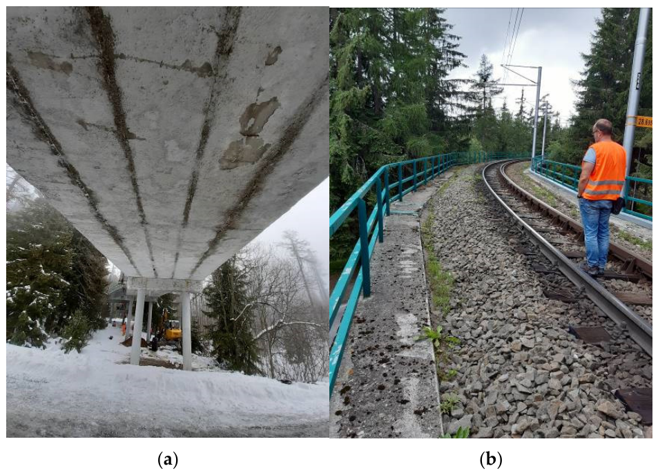
Firstly, the technical survey and diagnostics of the mentioned bridge called “Estakáda” on narrow-gauge electrified railway lines (see Figure 1) had to be carried out. The bridge object was built during 1968–1969 according to project documentation (PD) [29], so it was 54–55 years old. The given situation meant that it was necessary to carry out the visual inspections, diagnostics, verification of the real dimensions and material characteristics, evaluate the actual condition of the bridge, reveal eventual failures, and the calculate the load-carrying capacity [30,31,32,33]. Due to the new load, the possible reusing of the existing bridge was verified. The visual inspection and diagnostics were done in the middle of December 2021 and the load-carrying capacities calculations were done up to the end of May 2022.
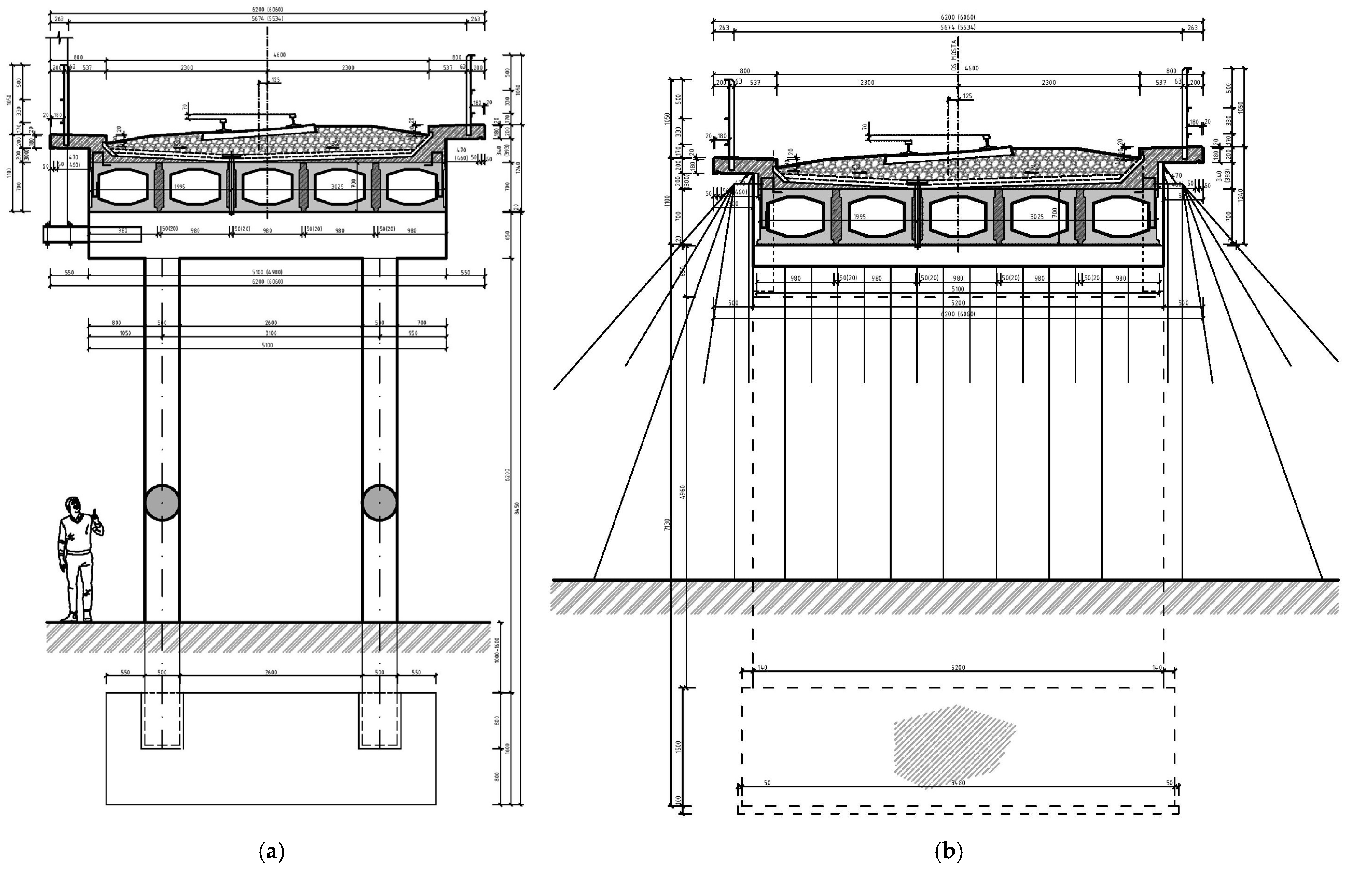
The bridge was made of precast prestressed post-tensioned girders of six single spans. The bridge superstructure consists of 5 prestressed girders in the transverse direction in one span with denotation KA 61 (box girder cross-section), of a length of 16.60 m in all 6 spans. The cornices with a sloped concrete slab above the box girders were created on the upper surface of box girders—this is not a connected structure (composite structure concrete slab-concrete box girders), the sloped concrete slab was created due to the drainage of the ballast (gravel bed) and is anchored only to the spandrel girders (edges of superstructure). From that it follows that, in the transverse direction, the girders are not coupled by a composite slab but statically perform as a “curtain slab”—there are longitudinal hinge connections between girders. Interestingly, these girders were not developed for the use on railway bridges, but for the road bridges. In this case, they could also be used on the railway bridge, since the bridge was not designed for the load model LM 71 (UIC 71), but only for the special train load (tram), which is a significantly smaller load and the box girders suited it. The total width of the bridge is from 6.06 to 6.20 m and free width between the bridge rails is 5.57 m (Figure 2).
The substructure consists of the two monolithic concrete gravity abutments with parallel hanged wings and five intermediate piers (partially prefabricated foundation bases with two columns and upper bridge cap). The prefabricated girders (box girders KA 61) are placed on reinforced concrete bridge caps using corcolite plates of thickness 20 mm (corcolite plates as bearings). It is a simple method of supporting the superstructure that was often used on bridges at the time of construction.
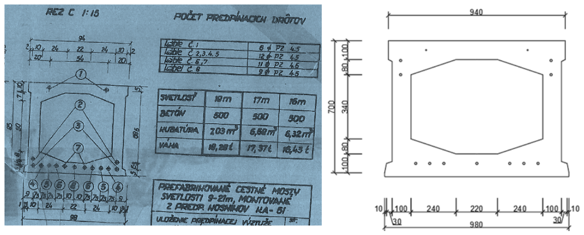
The clearances of the bridge are 16.18 m + 4 × 16.56 m + 16.18 m. In the longitudinal direction, it is a six-span structure (six separate simple spans, not a continuous girder) with a length of spans of 6 × 16.50 m. The box girders are 700 mm high, 940 mm wide at the top and 980 mm at the bottom.

3. Results from the Diagnostics

Before strengthening the bridge structure, it was necessary to first diagnose the bridge to determine its condition and whether it was possible to use reinforcement using prestressed CFRP strips. During the diagnostics, the non-destructive tests (NDT) and the semi-destructive tests (SDT) of concrete, the depth of carbonization, and identification of type of used reinforcement and prestressing steel were performed [34,35]. The content of chloride ions was also verified since it is the railway bridge over two roads.
The diagnostics were focused on the entire bridge structure (nonstructural parts and bridge accessories, bridge superstructure and substructure). Since this paper is focused on strengthening the superstructure using CFRP prestressing strips, in this chapter we will also focus mainly on failures related to the superstructure.
The precast prestressed box girders KA 61 were made of concrete of class C35/45 according to the NDT, using the Schmidt rebound hammer—NDT confirmed the assumption of the concrete class given in Catalog of box girders [36]. Only a Schmidt rebound hammer tester was used to determine the concrete grade of the box girders, because it was not possible to make drilling cores in the concrete beams due to the small dimensions of the girders’ cross-section—thin webs and slabs of the box girder. According to the original documentation [36], the post-tensioning was additionally made of cables composed of smooth wires ϕ 4.5 mm (in numbers 6 to 12)—that fact was also confirmed by diagnostics. The piers’ bridge caps and piers’ columns were made of concrete of grade C25/30. The abutments’ bridge caps and abutments’ webs were made of concrete only of grade C12/15. The quality of piers’ and abutments’ concrete grades were determined on cylindrical drilling cores and verified by the Schmidt rebound hammer. All the elements are reinforced by reinforcement type 10,400 (A III, fyk = 400 MPa). The reinforcements (position and mutual distances) have been scanned using the Hilty scanner PS 1000 and were verified using Profometer 5 or Bosh Wallscanner D-tect 150 Professional. The concrete cover thickness was in the range of 25–30 mm. The depth of concrete carbonation was measured and reached a value of 2 to 5 mm on the girders. In the case of piers’ caps and columns, the measured value was 10–15 mm. After calculating the content of chloride ions Cl to the expected amount of cement mass used in the production of concrete, the obtained values of chloride ions were in the range of 0.014 to 0.168% Cl/mc. It emerged that the content of chloride ions Cl/mc was for all the samples below the critical value for reinforced concrete (RC) structures (Ckrit = 0.4 Cl/mc) and prestressed concrete (PC) structures (Ckrit = 0.2 Cl/mc—additionally prestressed concrete) [37]. This is probably due to the fact that it is a railway bridge that bypasses two roads, but the structure is located in the protected area of High Tatras mountains, where salting of roads is prohibited.
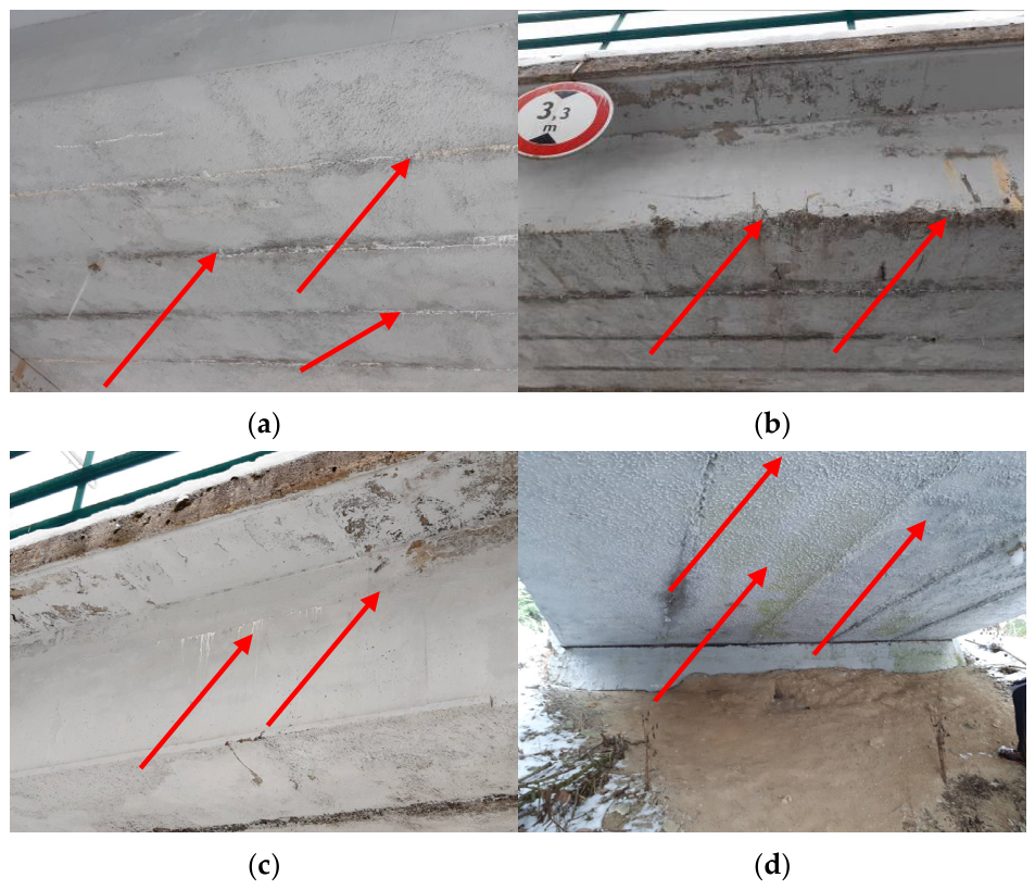
The following basic shortcomings were found on superstructure (Figure 3a–d):
-
The superstructure (prefabricated box girders) shows only minor damages;
-
The box girders still have a slight precambering, so it can be assumed that the prestressing is working well and is still functional; it follows that the prestressing steel anchorage is also functional, but this could not be verified due to the small width of dilation;
-
Water leakage between the box girders was found—probably due to insulation damage that could not be detected due to the ballast bed (Figure 3a,b,d);
-
The surface treatment that has been done recently has locally fallen off due to poor adhesion (Figure 3a–d);
-
Locally fallen off concrete cover layer at the stirrups—approximately 0 to 15 mm,
-
The load-bearing superstructure is only slightly leaking at the edges of the bridge structure at the places where the cornices are slightly damaged;
-
The box girders are mostly without cracks, longitudinal cracks were found only locally in some places in lengths from approx. 1.0 m to 2.0 m;
-
Concrete leaches from some cracks (local formation of drops and incrustation),
-
The reinforcement (stirrups) shows a slight corrosion, the prestressing steel was detected in three places, but no corrosion of the prestressing steel was detected, and it was found that the cable ducts were injected—it was verified by three boreholes;
-
The cement mortar between the beams was damaged, the joints were leaking, the mortar from joints dropped out in some places (Figure 3a,c);
-
The box girders in span no. 4 were slightly damaged (edges) from the road vehicles due to the low gauge clearance (Figure 3b);
-
The joint between the edge box girders and cornices—longitudinal cracks were detected between the edge girders and cornices in the longitudinal direction in each span (Figure 3c), some of which are leaking water and leaching. It can be considered that these longitudinal cracks indicated that the cornice parts on both sides should not be considered as a load-bearing members of the whole bridge cross-section (composite box girder–slab–cornice connected cross-section), because corrosion of the connecting reinforcement may occur in this part (t could not be verified). Thus, it was considered that the load-bearing structure of the bridge structure (cross-section) consists only of five box girders;
-
In span no. 6, a greenish surface was detected at the bottom of the box girders—no chemical analysis was done, but it may indicate bio corrosion (Figure 3d).

4. Calculation of the Bridge Load-Carrying Capacity and Verifying the Bridge

4.1. Modeling of the Superstructure

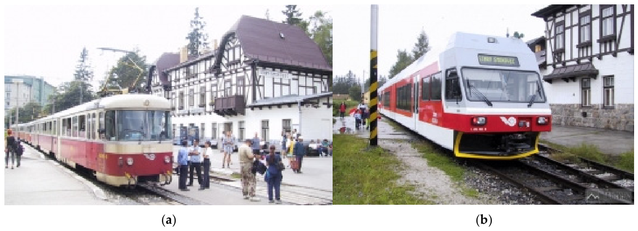
The calculation of the new load-carrying capacity was necessary due to the applied new load (new and heavier type of train compared to the one used before the reconstruction)—new Stadler GTW 2/6 EMU—OŽ 1000 train started to run on the line from 2021. This load has greater efficiency—greater axle forces and shorter distances than the original used train that previously provided traffic (EMU series 425.95). The originally used train EMU series 425.95 was 4-axle train (axis distances of the axles were 1.40 m + 3.95 m + 2.50 m), with a total weight of 28.77 tons (5.4 t + 5.52 t + 7.55 t + 10.3 t). The new type of trains is a double-wagon with 6 axles (axle distances are 1.90 m + 11.16 m + 2.48 m + 11.16 m + 1.90 m) with a total weight of 66.8 tons (2 × 9.2 t + 2 × 15 t + 2 × 9.2 t), so only the middle two axles (2 × 15 t = 30.0 t) weigh more than the entire original train (28.77 t) (see Figure 4).
First, the load-carrying capacity was verified on load LM 71, but due to the type of box girder used, it was verified that the load-carrying capacity was significantly less than 1.0 in all cases. There was no requirement to calculate the passage of the old load (EMU series 425.95) through the structure, as only the new load will be applied. Therefore, the resistance was compared only to the effects from the new load (new train), from which the passage of the railway traffic given by GTW 2/6 EMU was determined.
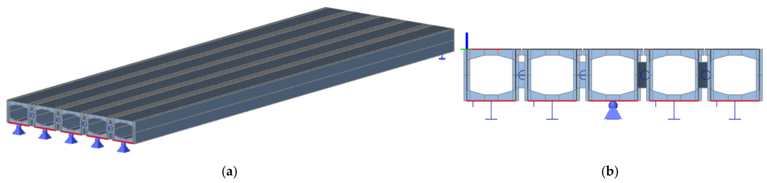
In the static calculation, it is a 6-span bridge structure, made of precast box girder members of the “KA 61” type, which, due to the structural solution of the whole structure, acts as six simple supported spans in the longitudinal and vertical directions—it is not 6-span continuous structure due to dilatations between spans. The spans have effective lengths of 6 × 16.00 m. Taking into account the arrangement and creation of the bridge cross-section from box girders of the “KA 61” type, without a composite reinforced concrete slab, but with a longitudinal hinged connection between the box girders, a calculation model was used to determine the response of the load-bearing structure to the load, taking into account the hinged connection of the box girders in the transverse direction as “curtain slab”. The crossing angle of structure with supports was considered to be perpendicular—the bridge is in an arch in ground view, the bridge caps are perpendicular to the track axis; therefore, the box girder spans are different—the maximum is 16.0 m. There is no longitudinal slope on the bridge and therefore the model was made as horizontal (longitudinal slope was not modeled). The transverse prestressing has not been done, so it was not modeled either. It is a spatial structure; therefore, the load-bearing superstructure was modeled as a spatial structure—individual prefabricated prestressed box girders were modeled as chambers of two walls thickness 0.10 m and two slabs thickness 0.10 m (slab-wall model taking into account the lower and upper slab with haunches and two end walls). The box girders created in this way were longitudinally joined by longitudinal hinges using a longitudinal horizontal slab in the middle of the height of the girders simulating the joint connection between the girders (on one side fixed into the wall of one girder and on the other side hinged to the wall of the other girder). Internal forces were evaluated using an integration chord. The 3D numerical model was created using the finite element method (FEM) using the Scia Engineer 2019 software system [38]. The input materials’ characteristics and dimensions of the box girder cross-section (see Figure 5) were taken from [36]. Since these are six separate spans, only one independent span was modeled (see Figure 6).
Since this was a single supported span structure, hinged supports of each box girder were considered at one end and sliding supports in the longitudinal direction on each box girder were modeled at the opposite end. Regarding the slab-wall model, the load was modeled directly on the upper slab part of each box girder. Loads were modeled as square and line loads. The load values were calculated through the volume weights of the individual layers and materials. The train load was also modeled through the square loads—the distribution of the load over the area was considered.
The surface cracks on the box girders were not modeled in FEM models. It did not appear that they were static cracks, which would affect the resistance of the cross-section. The dynamic analysis was not performed. Dynamic effects of the new load were taken into account using the static effects and a dynamic coefficient.
The calculation was performed for the superstructure, as well as for the substructure (piers—bridge caps, columns and footings). The values of materials and geometrical characteristics found on the superstructure and substructure, which were verified by diagnostics, were taken into account. The structure was verified according to the European standard STN EN 1992-2 [39], valid for the bridge design. During the calculation, the influence of the environment and other effects, such as fatigue, corrosion of stirrups and so on, were taken into account as well [40,41,42,43,44,45,46]. Since the corrosion of the prestressing steel was not detected, only the corrosion of the stirrups was taken into account in the calculation by changing the cross-sectional area and its effect on the reduction in shear resistance.

4.2. Modeling of the Substructure

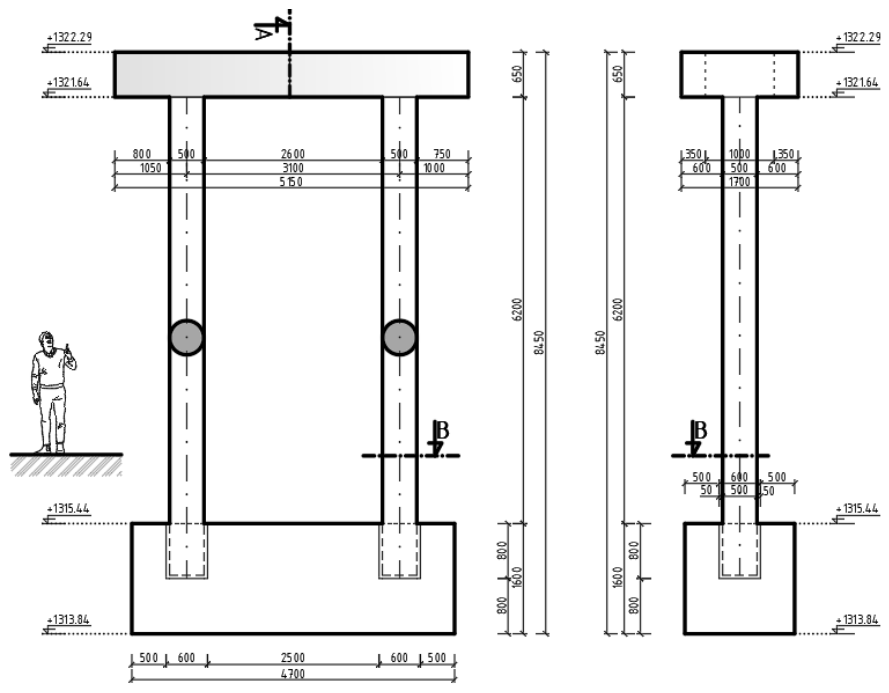
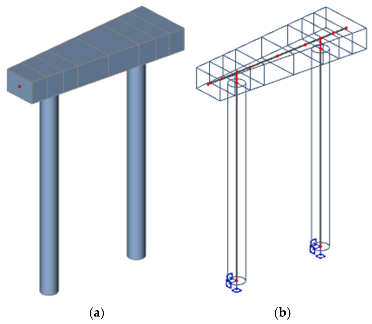
Piers of substructure (piers P1 to P5) were modeled as a member model, so they consisted of vertical and horizontal elements corresponding to the actual dimensions. These are vertical columns with a circular cross-section, the diameter of which is 500 mm and the horizontal bridge cap in the shape of a rectangle of a height of 650 mm and a trapezoidal ground plan of a variable width of 1000 to 1700 mm (Figure 7). The axial distance of the columns was 3.10 m, and the maximum height for columns of piers P5 was considered to be 6.2 m. Each pier performs statically as a console in the longitudinal direction of the bridge and as a frame structure in the transverse direction. The support was considered as fixed. The model was loaded with vertical and horizontal reactions, obtained from the 3D numerical models of individual superstructure spans, which are the same in each span due to the character of the bridge. The 3D numerical model is shown in Figure 8.

4.3. Results from Modeling and Calculation

The superstructure was assessed for moment resistance, shear resistance and stress limitations (concrete in compression, concrete in tension (decompression condition), and steel cables in tension). The transition to the new required load was verified—a special set GTW 2/6.
Since this was a single supported span structure, the maximum moments and the corresponding maximum stresses (compressive in the concrete and tensile in the prestressing reinforcement) occurred in the middle of the span. The maximum shear forces were logically at the points of the supports.
The maximum compressive stress in concrete, during the stress verification, was equal to 14.74 MPa (upper part of the cross-section in the middle of the span), which is smaller than permitted 21.0 MPa (for C 35/45: 0.6 fck = 0.6 × 35.0 = 21.0 MPa). The condition of decompression was verified in the bottom part of the cross-section (tensile part)—the compression stresses had to be demonstrated. After the calculation, the tensile stress in the lower part in the middle of the span was equal to 2.70 MPa, so the condition of decompression was not met.
The substructure was assessed for moment resistance, shear resistance and stress limitations in the case of the bridge cap and footing, and for the combination of moment and normal force resistance and shear resistance in the case of columns. The stresses in the base joints (contact between the footing and a mold) were also assessed.
The results show that:
  • Superstructure:
    -
    Girders of a length of 16.6 m (all six spans) were not suitable for transit (new loads given by the GTW 2/6) due to the insufficient design moment resistance in bending;
    -
    Girders of a length of 16.6 m (all six spans) were not suitable for transit (new loads given by the GTW 2/6) due to the tensile stresses in concrete at the bottom edge of the cross-section—the tensile stresses in the concrete were not satisfactory (the entire section was not compressed, the decompression was not satisfactory);
  • Substructure:
    -
    Piers’ bridge caps were not suitable for transit (new loads) due to the insufficient moment design resistance in bending;
    -
    Piers’ columns were not suitable for transit (new loads) due to the insufficient design resistance in combination of moment and normal forces.
Diagnostics and load-carrying calculation have shown that the bridge load-carrying capacity did not meet the current valid requirements and conditions, but the bridge can be repaired to the level required by current standards and regulations, with the necessary costs. It was necessary to strengthen the box girders and piers (bridge cups and columns).

5. Conceptual Design of the Bridge Strengthening

In an effort to ensure the reliability of the bridge as simply and quickly as possible, it was decided that the existing bridge would not be demolished and replaced by a new bridge, but that it would be strengthened. This reduced the CO2 footprint—it is about reusing existing members/structure. The construction of a new bridge would take a longer period of time and would mean high costs for demolition works and for the construction of a new bridge. Due to the nature of the load-bearing members of the superstructure and substructure, a different approach was used in their strengthening.

5.1. Strengthening of the Superstructure

In the case of the superstructure, which is not suitable for bending stresses and moment resistance, it was decided to use prestressed CFRP strips for strengthening. The idea was to perform the bridge strengthening during its operation, i.e., to minimize the concreting (e.g., by creating/concreting a new composite slab on the upper sides of the box girders, which would mean the need to stop operation on the bridge due to the removal of the ballast bed). It was possible to use the prestressed CFRP strips or prestressing steel. After an agreement between the designer and the investor, a decision was made to use the prestressed CFRP strips, which increased the design moment resistance, and at the same time, eliminated tensile stresses in the cross-section. This is one of the first applications of the use of prestressed CFRP strips for bridge strengthening, not only in Slovakia, but in Central Europe as well. In the case of strengthening the railway bridge, this is the first use.

5.1.1. Sensitivity Analysis

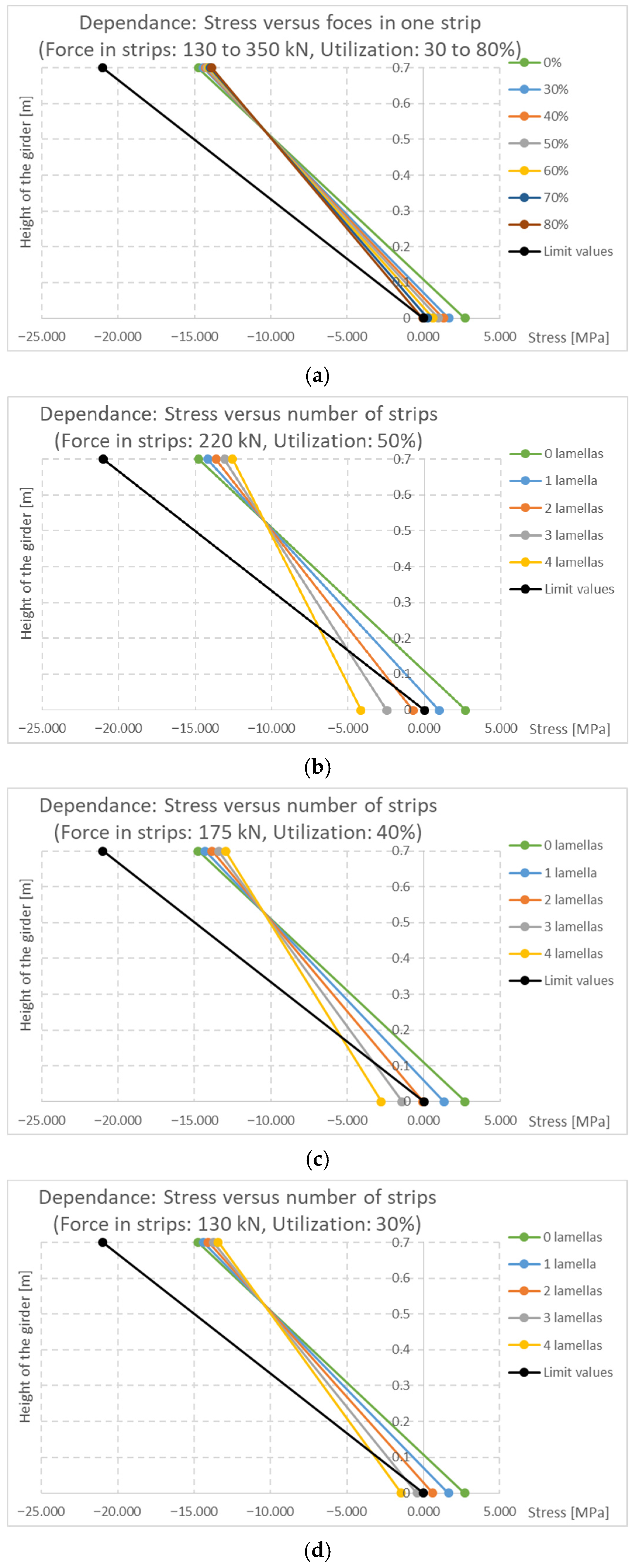
Firstly, a sensitivity analysis was performed to verify the correctness of the design, the number of strips and the required force in the strips.
The force in the strips depends on the degree of utilization of the strips. It is recommended to use the strips with a maximum of 50% of the tensile stresses, which in this case corresponds to a force in the strip equal to 218.4 kN (rounded to 220 kN). Therefore, prestressing with one strip with different utilization of the strip was first considered in order to obtain an overall view on strengthening. In this case, 0% tension in the strip (without strengthening) was considered, and then successive utilization at 30%, 40%, 50%, 60%, 70% and 80%, which corresponded to strip forces of 130 kN, 175 kN, 220 kN, 260 kN, 305 kN and 350 kN (Figure 9). The results show that it is necessary to design more than one strip per box girder cross-section, because for the cross-section to be suitable, the strip utilization would have to be up to 80%, which is no longer allowed (max. 50%). Therefore, in the following studies, changing the number of strips (0 strip (without strengthening) up to 4 strips) at different levels of strip utilization was considered: 50% utilization (force 220 kN), 40% utilization (force 175 kN) and 30% utilization (force 130 kN). The results of the sensitivity analysis show that the optimal number of strips per box girder of height 0.7 m is 2 strips at a utilization of 40% (force 175 kN). The sensitivity analysis shows a greater influence of the number of strips on the tensile stresses in the concrete than on the compressive stresses in the concrete along the height of the box girders cross-section. The stresses were compared with the limit values of 21.0 MPa in compression in the concrete in the upper fibers and zero tensile stress in the lower fibers of the box girder cross-section.
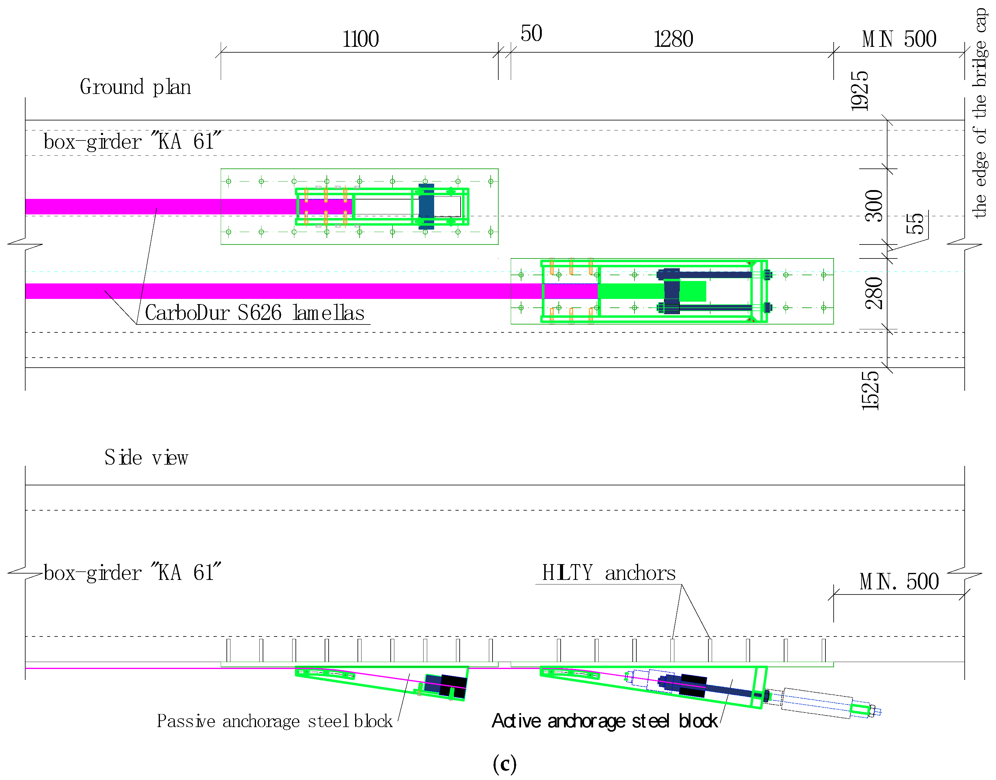
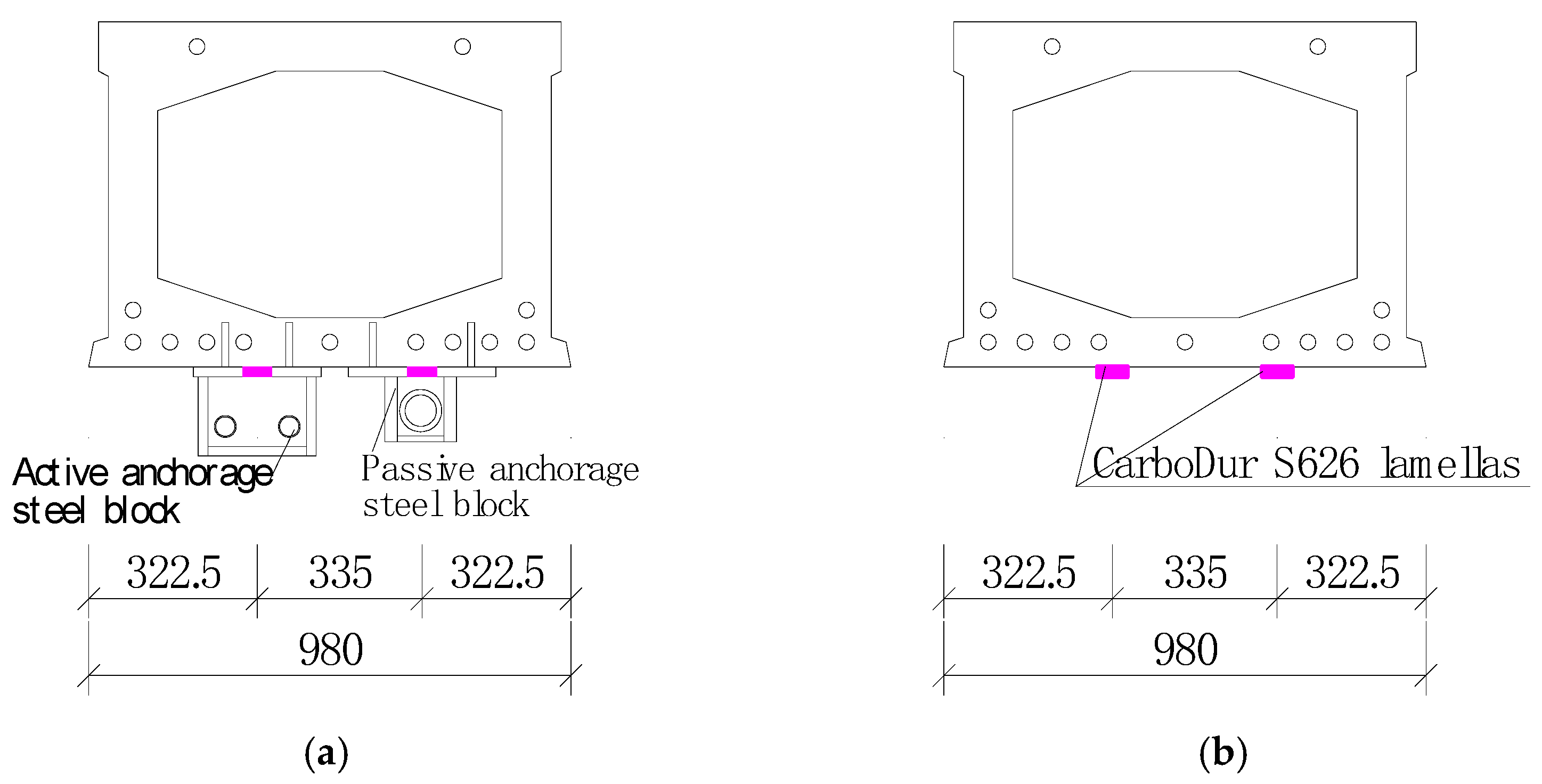
Resulting from the achieved values, to strengthen each box girder, two pieces of CarboDur S626 strips (cross-section dimensions are 60 × 2.6 mm) were used according to the sensitivity analysis, which had to be prestressed to a prestressing force of 175 kN. The characteristic strength of the strip (5% quantile) was considered fL,k = 2800 MPa, and the modulus of elasticity was considered EL,k = 165,000 MPa. The anchoring of the strips was provided using steel anchor blocks, certified for prestressing these strips by StressHead Company (Figure 10). Anchoring of steel anchors to the concrete box girders was done using the Hilty bolts. The CFRP strips were modeled as elements stressed only by tension at the eccentricity to the box girder center of gravity. In the resistance of the cross-section, it was enough to consider them as loaded by a force on the eccentricity, since it is a simply supported beam (without the influence of prestressing on a statically indeterminate structure).
After the strengthening, the maximum compressive stress in concrete during the stress verification was equal to 13.86 MPa (upper part of the cross-section in the middle of the span), which is smaller than the permitted 21.0 MPa. The compressive stress in the lower part, in the middle of the span, was equal to 0.07 MPa, so the whole cross-section was in compression and the condition of decompression was met.

5.1.2. Nonlinear Numerical Analysis

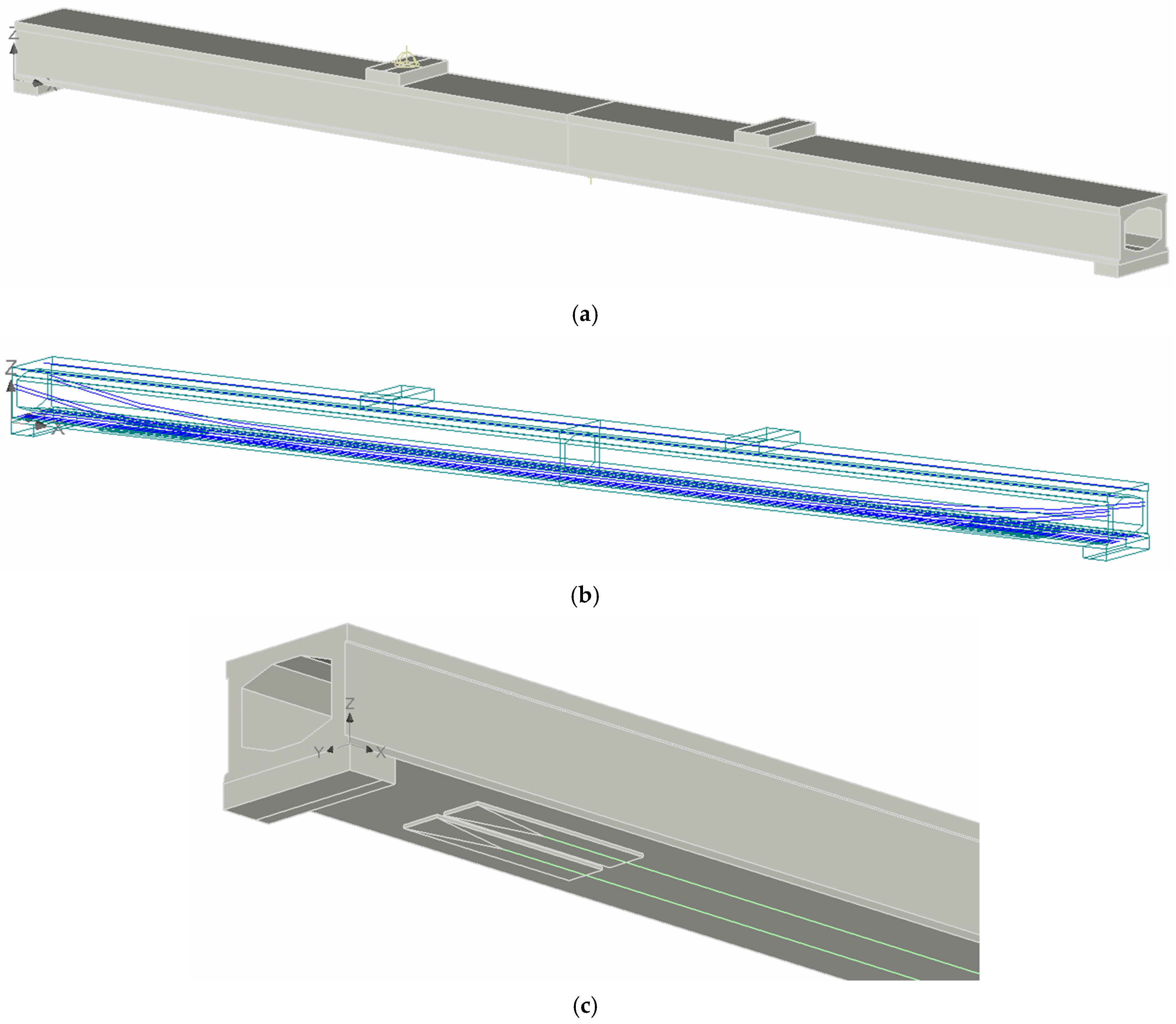
The computational model was developed in the Atena 3D-Program version: 5.7.0.19867 software [47], which is intended for nonlinear analysis of concrete and detailed modeling and assessment of concrete members. The geometry of the girder was based on the project documentation (PD) [29], and the cross-section corresponded to the values obtained from diagnostic measurements (Figure 11).
The prestressing of bonded cables was considered according to the design documentation [36]. External prestressing (prestressed CFRP strips) was applied at the bottom edge of the beam in the form of unbonded tendons placed on a steel distribution plate. The material properties were defined using the “3D NonLinCementitious 2” material model [47].
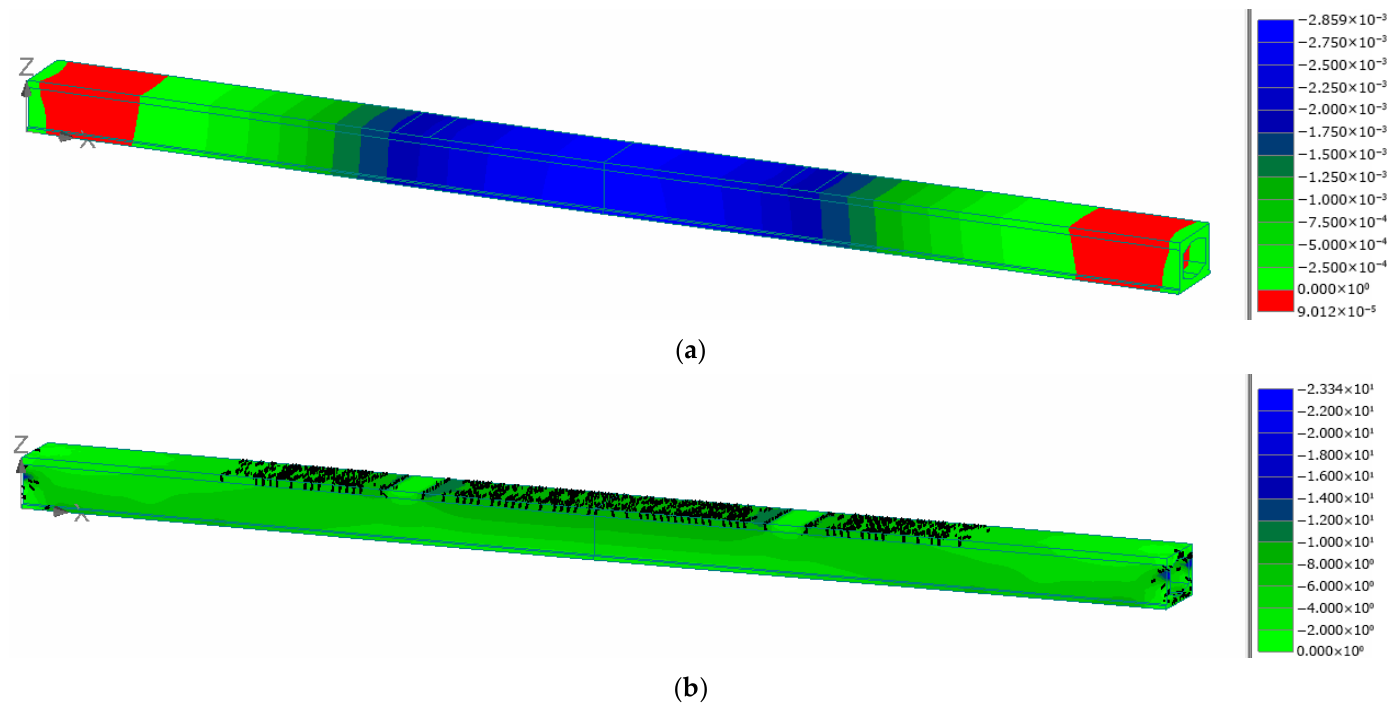
The girder was supported at both ends and loaded by controlled deformation. For the evaluation of results, monitoring points were placed at midspan to track the girder deflection. The model was loaded until a midspan deflection of 2.7 mm was reached. This value was adopted as a reference based on load testing results performed on identical bridge structures to verify the nonlinear model.
The results from the numerical model are shown in Figure 12. The midspan deflection of the numerical model of the girder reached 2.859 mm (Figure 12a). It can be concluded that the numerical model successfully simulated the measured values and that it was well calibrated for the given problem.
The stress distribution over the cross-section height indicates that no tensile stresses developed at this level of deformation. This means that the entire cross-section remained in compression (Figure 12b). The maximum compressive stress in the top slab reached 12.0 MPa, which is in good agreement with the linear analysis. Microcracks that developed in the top slab of the girder have no structural significance and do not compromise the durability of the structure. Their width is well below the limit value of 0.2 mm, as the crack widths obtained from the numerical model are approximately not more than 0.0361 mm.
The results show that the nonlinear model also confirmed the correctness of the method of strengthening the bridge using prestressed CFRP strips. This method of strengthening increased the load-carrying capacity and ensured the decompression condition.
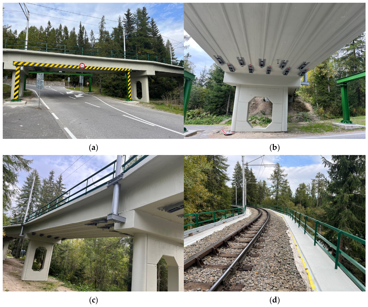
In terms of protection of the CFRP strips and steel anchorages, a one-component solvent-based methacrylic resin-based coating, resistant to weathering, alkalis and aging in the color of the concrete, was used on the CFRP strips themselves and the steel elements. (see Figure 13). The coating protects the surfaces from aggressive atmospheric influences and supports the self-cleaning effect of the loaded surface. It does not affect the characteristic structure of concrete or other surfaces.

5.2. Strengthening of the Substructure

The abutments did not need to be strengthened, so only their surface was treated. The piers had to be strengthened to increase the bending resistance in the middle of the span of a bridge cap and to increase the resistance of the vertical columns. Due to the failures in the bridge caps (net of vertical and mainly horizontal cracks), the strengthening was not chosen in such a way that independent strengthening of the bridge caps (e.g., by adding reinforcement or CFRP strips) and columns (e.g., concreting a new layer around the cross-section) was used, but an infill system was chosen between the two columns, bridge cap and footing, using a web with an opening. This made it possible to strengthen not only the columns for stresses by a combination of normal forces and moments, but the bridge caps in bending as well. An opening in the web (instead of a full web) was chosen to “light up” the area under the bridge.
A view of the strengthened bridge structure is shown in Figure 13.

6. Conclusions

One of the possible ways to strengthen concrete bridges is strengthening using prestressed CFRP strips. This is a modern technology using modern materials, which is not yet completely common in practice. Therefore, it is very rare to find a solution to apply this strengthening method on a real bridge, which is presented in this paper. This is preliminary data obtained not only from measurements in the laboratory but also in situ. In this case, it turned out to be a better, simpler and faster method of reinforcement than using, for example, an additional UHPC layer, or UHPFRC layer [48,49,50,51]. Results of diagnostics and calculation of the load-carrying capacity of the bridge “Estakáda” on the railway line between Štrbské Pleso and Starý Smokovec, in the northern part of Slovakia, are shown in this paper. The bridge object was diagnosed as a part of modernization of the railway line, and its possible reuse was verified. The results of diagnostics and calculation have shown that the bridge object is in a satisfactory state (condition), but it does not satisfy the load-carrying capacity for the new type of train (new load), but that it could be strengthened to fulfill the new code requirements.
To be able to continue to use the bridge, it was recommended to reconstruct and strengthen it. The most promising and appropriate way for strengthening seemed to be the use of prestressed CFRP strips, as it was used in previous cases [26].
The strengthened bridge has been in operation for about three years at the time of writing the paper (after the reconstruction). In order to verify the correctness of the design and the method of strengthening, it was recommended that at least two times a year (every six months) for at least the first 5 years, the bridge be inspected and the condition of the prestressing strips and anchors checked. During the regular inspections, no malfunctions or damage have occurred so far that would indicate improper functioning of the system. So far, the method of used strengthening seems to perform and was chosen correctly, as the bridge did not have to be demolished and the existing structure was used again with optimal reconstruction costs, for minimal reconstruction time and during the bridge operation. Thus, it has been proven that prestressed CFRP strips can be used for dynamically stressed railway bridges as well.

Author Contributions

Conceptualization, P.K., O.K. and M.V.; methodology, P.K., M.V. and M.Z.; validation, P.K., F.B. and M.F.; formal analysis, P.K., M.Z., J.P. and M.V.; investigation, M.Z., F.B., J.P. and M.F.; resources, P.K., O.K. and M.V.; data curation P.K. and M.Z.; writing—original draft preparation, P.K. and M.V.; writing—review and editing, P.K., M.Z. and O.K.; visualization, P.K. and M.Z.; supervision, P.K., F.B., J.P. and M.V. All authors have read and agreed to the published version of the manuscript.

Funding

This research is supported by the Slovak Research and Development Agency under contract No. APVV-23-0626, and by Research Project No. 1/0321/24.

Data Availability Statement

Some or all data, and results used during the work are available from the corresponding author by request.

Conflicts of Interest

The authors declare no conflicts of interest.

References

  1. Akhnoukh, A.K. Accelerated bridge construction projects using high performance concrete. Case Stud. Constr. Mater. 2020, 10, e00313. [Google Scholar] [CrossRef]
  2. Farzad, M.; Rastkar, S.; Sadeghnejad, A.; Azizinamini, A. Simplified Method to Estimate the Moment Capacity of Circular Columns Repaired with UHPC. Infrastructures 2019, 4, 45. [Google Scholar] [CrossRef]
  3. Fehrey, D.N. Reconstruction as Deterioration Indicator for Operational Structural Performances of Bridge Material. Infrastructures 2022, 7, 96. [Google Scholar] [CrossRef]
  4. Kishore, R.; Nasiry, N.Z.; Rujhan, A.M. Strengthening of reinforced concrete beams using CFRP laminates. Asian J. Civ. Eng. (BHRC) 2016, 17, 159–167. [Google Scholar]
  5. Havez, A.A.; Al-Mayah, A. Flexural Strengthening of Concrete Structures Using Externally Bonded and Unbonded Prestressed CFRP Laminates: A Literature Review. J. Compos. Constr. 2023, 27, 03123001. [Google Scholar] [CrossRef]
  6. Pisani, M.A. Behaviour under long-term loading of externally prestressed concrete beams. Eng. Struct. 2018, 160, 24–33. [Google Scholar] [CrossRef]
  7. Kasan, J.L.; Harries, K.; Miller, R.; Brinkman, R. Repair of Prestressed-Concrete Girders Combining Internal Strand Splicing and Externally Bonded CFRP Techniques. J. Bridge Eng. 2014, 19, 200–209. [Google Scholar] [CrossRef]
  8. Issa, C.A.; AbouJouaded, A. Carbon Fiber Reinforced Polymer Strengthening of Reinforced Concrete Beams: Experimental Study. J. Archit. Eng. 2004, 10, 121–125. [Google Scholar] [CrossRef][Green Version]
  9. Haritos, N.; Hira, A. Repair and strengthening of RC flat slab bridges using CFRPs. Compos. Struct. 2004, 66, 555–562. [Google Scholar] [CrossRef]
  10. Breveglieri, M.; Czaderski, C. Reinforced concrete slabs strengthened with externally bonded carbon fibre-reinforced polymer strips under long-term environmental exposure and sustained loading. Part 1: Outdoor experiments. Compos. Part C Open Access 2022, 7, 100239. [Google Scholar] [CrossRef]
  11. Al-Janabi, M.; Fathuldeen, S.W. Behavior of RC beams strengthened with NSM CFRP strips under flexural repeated loading. Struct. Eng. Mech. 2019, 70, 67–80. [Google Scholar] [CrossRef]
  12. Yoshitake, I.; Kim, Y.J.; Yumikura, K.; Hamada, S. Moving-Wheel Fatigue for Bridge Decks Strengthened with CFRP Strips Subject to Negative Bending. J. Compos. Constr. 2010, 14, 784–790. [Google Scholar] [CrossRef]
  13. Hasegawa, H.; Kato, T.; Shimose, K.; Yoshitake, I. Moving-Wheel Load Test of a Cantilevered RC Slab Strengthened with Bond-Improved Ultra-High Modulus CFRP Rods. In Proceedings of the 8th International Conference on Advanced Composite Materials in Bridges and Structures. Lecture Notes in Civil Engineering; Benmokrane, B., Mohamed, K., Farghaly, A., Mohamed, H., Eds.; Springer: Cham, Switzerland, 2023; Volume 278. [Google Scholar] [CrossRef]
  14. Ma, S.; Bunnori, N.M.; Choong, K.K. Experimental Study on Shear Strengthening of Reinforced Concrete Box Beam by CFRP. Iran. J. Sci. Technol. Trans. Civ. Eng. 2020, 44, 1075–1085. [Google Scholar] [CrossRef]
  15. Piątek, B.; Siwowski, T. Research on the new CFRP prestressing system for strengthening of RC structures. Archit. Civ. Eng. Environ. 2017, 3, 81–87. [Google Scholar] [CrossRef]
  16. Piątek, B.; Siwowski, T. Research on the new bridge strengthening system with prestressed CFRP strips. In Proceedings of the Conference: Fourth International Symposium on Life-Cycle Civil Engineering—IALCCE 2014; CRC Press: Boca Raton, FL, USA, 2014; pp. 2007–2011. [Google Scholar]
  17. Michels, J.; Staśkiewicz, M.; Czaderski, C.; Kotynia, R.; Harmanci, Y.E.; Motavalli, M. Prestressed CFRP Strips for Concrete Bridge Girder Retrofitting: Application and Static Loading Test. J. Bridge Eng. 2016, 21, 04016003. [Google Scholar] [CrossRef]
  18. Sayed-Ahmed, E.Y.; Riad, A.H.; Shrive, N.G. Flexural strengthening of precast reinforced concrete bridge girders using bonded carbon fibre reinforced polymer strips or external post-tensioning. Can. J. Civ. Eng. 2004, 31, 499–512. [Google Scholar] [CrossRef]
  19. Rosenboom, O.; Rizkalla, S. Behavior of Prestressed Concrete Strengthened with Various CFRP Systems Subjected to Fatigue Loading. J. Compos. Constr. 2006, 10, 492–502. [Google Scholar] [CrossRef]
  20. Piątek, B.; Siwowski, T. Development of the new cfrp strip prestressing system for structural strengthening. In Proceedings of the 9th International Conference on Fibre-Reinforced Polymer (FRP) Composites in Civil Engineering (CICE 2018); International Institute for FRP in Construction (IIFC): Paris, France, 2018; pp. 710–717. [Google Scholar]
  21. Piątek, B.; Siwowski, T.; Michalowski, J.; Blazewicz, S. Flexural Strengthening of RC Beams with Prestressed CFRP Strips: Development of Novel Anchor and Tensioning System. J. Compos. Constr. 2020, 24, 04020015. [Google Scholar] [CrossRef]
  22. Kim, Y.J.; Wright, G.; Green, M. Flexural Strengthening of RC Beams with Prestressed CFRP Sheets: Development of Nonmetallic Anchor Systems. J. Compos. Constr. 2008, 12, 35–43. [Google Scholar] [CrossRef]
  23. Kim, Y.J.; Hyun, S.W.; Kang, J.-Y.; Park, J.-S. Anchorage configuration for post-tensioned NSM CFRP upgrading constructed bridge girders. Eng. Struct. 2014, 79, 256–266. [Google Scholar] [CrossRef]
  24. Siwowski, T.W.; Siwowska, P.; Wiater, A. The strengthening of a steel bridge with prestressed CFRP strips. In Proceedings of the 9th International Symposium on Steel Bridges; IOP Conf. Series: Materials Science and Engineering; IOP Publishing: Bristol, UK, 2018; Volume 419, p. 012037. [Google Scholar] [CrossRef]
  25. Ochi, N.; Matsumura, M.; Hisabe, N. Experimental Study on Strengthening Effect of High Modulus CFRP Strips with Different Adhesive Length Installed onto the Lower Flange Plate of I Shaped Steel Girder. Procedia Eng. 2011, 14, 506–512. [Google Scholar] [CrossRef][Green Version]
  26. Koteš, P.; Vavruš, M.; Moravčík, M. Diagnostics and Evaluation of Bridge Structures on Cogwheel Railway. In Proceedings of the 1st Conference of the European Association on Quality Control of Bridges and Structures; EUROSTRUCT 2021; Lecture Notes in Civil Engineering; Springer: Berlin/Heidelberg, Germany, 2021; Volume 200, pp. 93–101. [Google Scholar]
  27. Miano, A.; Mele, A.; Ragione, I.D.; Fiorillo, A.; Di Ludovico, M.; Prota, A. Impact of the Structural Defects on Risk Assessment of Concrete Bridges According to the Italian Guidelines 2020. Infrastructures 2023, 8, 135. [Google Scholar] [CrossRef]
  28. Medvediev, K.; Kharchenko, A.; Stakhova, A.; Yevseichyk, Y.; Tsybulskyi, V.; Bekö, A. Methodology for Assessing the Technical Condition and Durability of Bridge Structures. Infrastructures 2024, 9, 16. [Google Scholar] [CrossRef]
  29. Project documentation according to design—Nové Štrbské Pleso, construction of railway station and bridge Estakáda, contains: Technical report, drawing documentation and results from the proof-load test, processed by: Boroš Ján, Sudop, center 05-Košice, 04-07/1968. (In Slovak)
  30. Koteš, P.; Vičan, J. Reliability-based evaluation of existing concrete bridges in Slovakia according to Eurocodes. In The Fourth International fib Congress 2014, Mumbai, Improving Performance of Concrete Structures, Proceedings, Mumbai, India; IMC-FIB: Lausanne, Switzerland, 2014; pp. 227–229. [Google Scholar]
  31. Koteš, P.; Vičan, J. Recommended reliability levels for the evaluation of existing bridges according to Eurocodes. Struct. Eng. Int. Int. Assoc. Bridge Struct. Eng. (IABSE) 2013, 23, 411–417. [Google Scholar] [CrossRef]
  32. Koteš, P.; Prokop, J.; Strieška, M.; Vičan, J. Calibration of partial safety factors according to Eurocodes. In Proceedings of the 26th R-S-P Seminar 2017 Theoretical Foundation of Civil Engineering, Warsaw, Poland; MATEC Web of Conferences; EDP Sciences: Les Ulis, France, 2017; Volume 117, p. 00088. [Google Scholar] [CrossRef]
  33. Kala, Z. Sensitivity Analysis in Probabilistic Structural Design: A Comparison of Selected Techniques. Sustainability 2020, 12, 4788. [Google Scholar] [CrossRef]
  34. Odrobiňák, J.; Hlinka, R. Degradation of steel footbridges with neglected inspection and maintenance. Procedia Eng. 2016, 156, 304–311. [Google Scholar] [CrossRef]
  35. Malhotra, V.M.; Carino, N.J. Handbook on Nondestructive Testing of Concrete, 2nd ed.; CRC Press: Boca Raton, FL, USA, 2004; 384p. [Google Scholar]
  36. Catalog—Prefabricated road bridges with a width of 9-12-15-18-21 m mounted from prestressed beams KA-61. Complete type base, part A, 1961, Dopravoprojekt Bratislava. (In Slovak)
  37. STN EN 206+A2; Concrete. Specification, Performance, Production and Conformity. Slovak Office of Standards, Metrology and Testing: Bratislava, Slovakia, 2021.
  38. Scia Engineer. Scia Engineer Basics. Terminology, Layout, Settings, Basic Working Tools. 2019. Available online: https://help.scia.net/download/18.0/en/Basics_enu.pdf (accessed on 6 May 2018).
  39. STN EN 1992-2; Eurocode 2: Design of Concrete Structures. Part 2: Concrete Bridges—Design and Detailing Rules. Slovak Office of Standards, Metrology and Testing: Bratislava, Slovakia, 2007.
  40. Bujnakova, P.; Kralovanec, J.; Perkowski, Z.; Bouchair, A. Verification of precast concrete girder bridge under static load. Civ. Environ. Eng. 2022, 18, 760–767. [Google Scholar] [CrossRef]
  41. Krivy, V.; Kubzova, M.; Kreislova, K.; Urban, V. Characterization of corrosion products on weathering steel bridges influenced by chloride deposition. Metals 2017, 7, 336. [Google Scholar] [CrossRef]
  42. Bobalo, T.; Blikharskyy, Y.; Kopiika, N.; Volynets, M. Serviceability of RC Beams Reinforced with High Strength Rebar’s and Steel Plate. In Proceedings of Advances in Resource-Saving Technologies and Materials in Civil and Environmental Engineering (CEE 2019); Lecture Notes in Civil Engineering; Springer: Cham, Switzerland, 2020; Volume 47, pp. 25–33. [Google Scholar]
  43. Macho, M.; Ryjaček, P. The impact of the severe corrosion on the structural behavior of steel bridge members. In Advances and Trends in Engineering Sciences and Technologies—Proceedings of the International Conference on Engineering Sciences and Technologies, ESaT 2015; CRC Press: Boca Raton, FL, USA, 2015; pp. 23–128. [Google Scholar]
  44. Ryjaček, P.; Macho, M.; Stančík, V.; Polák, M. The Deterioration and assessment of steel bridges. In Maintenance, Monitoring, Safety, Risk and Resilience of Bridges and Bridge Networks—Proceedings of the 8th International Conference on Bridge Maintenance, Safety and Management, IABMAS 2016; CRC Press: Boca Raton, FL, USA, 2016; pp. 1188–1195. [Google Scholar]
  45. Hollý, I.; Bilčík, J.; Gajdošová, K. Numerical modeling of reinforcement corrosion on bond behaviour. In Proceedings of the International Multidisciplinary Scientific GeoConference Surveying Geology and Mining Ecology Management, SGEM, 249; STEF92 Technology: Sofia, Bulgaria, 2016; pp. 191–196. [Google Scholar]
  46. Prokop, J.; Vican, J. Comparison of beam-column resistance according to European Standards. In Proceedings of the 13th International Scientific Conference on Sustainable, Modern and Safe Transport (Transcom 2019); Transportation Research Procedia; Elsevier: Amsterdam, The Netherlands, 2019; Volume 40, pp. 883–890. [Google Scholar]
  47. Červenka, V.; Jendele, L. ATENA Program Documentation, Part 1, Theory; Cervenka Consulting s.r.o.: Prague, Czechia, 2007; 354p. [Google Scholar]
  48. Čítek, A.; Čítek, D.; Šulc, V.; Foglar, M.; Hájek, R.; Hurtig, K.; Vavruš, M. Preliminary Verification of Experimental Tests of the Explosion Resistance of Composite Steel-Concrete Elements Made of UHPFRC and NSC. Civ. Environ. Eng. 2025, 21, 1402–1415. [Google Scholar] [CrossRef]
  49. Tu’ma, N.H.; Hammooud, M.N.; Mohsin, R.D. Flexural Strength Estimation for Hollow Cross-Section Simply Supported UHPC Beams. Civ. Environ. Eng. 2021, 17, 476–484. [Google Scholar] [CrossRef]
  50. Safaa, A.; Majid, M.A.K. State of Research on Shear Strengthening / Repairing of RC Beams with Ultra-High-Performance Concrete (UHPC). Civ. Environ. Eng. 2025, 21, 1326–1347. [Google Scholar] [CrossRef]
  51. Hurtig, K.; Čítek, D.; Holý, M.; Koteš, P.; Čítek, A. Experimental Assessment of Durability in 3D Printed Cementitious Materials. Civ. Environ. Eng. 2025, 21, 1384–1401. [Google Scholar] [CrossRef]
Figure 1. A view of the bridge: (a) bottom view; (b) view of the railway ballast on the bridge.
Infrastructures 11 00180 g001
Figure 2. The bridge cross-section: (a) in the place of a pier; (b) in the place of an abutment.
Infrastructures 11 00180 g002
Figure 3. The failures of the bridge superstructure: (a) leakage between girders; (b) the girders in span no. 4 were slightly damaged (edges) by road vehicles; (c) longitudinal crack between the edge box girder and the cornice; (d) and detail of greenish surface of the superstructure on the bottom side.
Infrastructures 11 00180 g003
Figure 4. Train models (considered as loads): (a) old type—EMU series 425.95; (b) new type—Stadler GTW 2/6 EMU—OŽ 1000.
Infrastructures 11 00180 g004
Figure 5. The example of cross-sectional dimensions of box girders in the catalog from the year 1961 [36].
Infrastructures 11 00180 g005
Figure 6. The numerical 3D FEM model of the bridge superstructure: (a) 3D view; (b) cross-section.
Infrastructures 11 00180 g006
Figure 7. The shape and dimensions of piers.
Infrastructures 11 00180 g007
Figure 8. The numerical 3D FEM model of the piers: (a) 3D view; (b) model of individual elements.
Infrastructures 11 00180 g008
Figure 9. The sensitivity analysis of the effects on stresses in concrete in cross-section: (a) effect of utilization in one strips on stresses; (b) effect of number of strips on stresses at utilization 50% (force 220 kN); (c) effect of number of strips on stresses at utilization 40% (force 175 kN); (d) effect of number of strips on stresses at utilization 30% (force 130 kN).
Infrastructures 11 00180 g009
Figure 10. The strengthening of the superstructure—details: (a) cross-section in the place of the anchorage; (b) cross-section in the middle of the span; (c) ground plan and side view.
Infrastructures 11 00180 g010aInfrastructures 11 00180 g010b
Figure 11. The nonlinear numerical model: (a) numerical model—shape of the girder; (b) prestressing cables profile; (c) detail of prestressing anchorage.
Infrastructures 11 00180 g011
Figure 12. The results from the numerical model: (a) deformation of girder (structure); (b) stresses in cross-section.
Infrastructures 11 00180 g012
Figure 13. The bridge after the reconstruction: (a) steel frame portal in front of the bridge superstructure over the road; (b) strengthening of the superstructure using prestressed CFRP strips; (c) side view of a superstructure and piers; (d) view of the ballast bed and reconstructed cornices and rails.
Infrastructures 11 00180 g013
Disclaimer/Publisher’s Note: The statements, opinions and data contained in all publications are solely those of the individual author(s) and contributor(s) and not of MDPI and/or the editor(s). MDPI and/or the editor(s) disclaim responsibility for any injury to people or property resulting from any ideas, methods, instructions or products referred to in the content.