Article

Experimental and Numerical Evaluation of Shear Performance of NSM CFRP Strengthened RC Beams Exposed to Elevated Temperatures


by
Ahmad Al-Khreisat
1,*,
Hany A. Abdalla
1,2 and
Mu’tasime Abdel-Jaber
3
1
Structural Engineering Department, Faculty of Engineering, Cairo University, Giza 12613, Egypt
2
Department of Civil Engineering, College of Technological Studies, PAAET, Kuwait 70451, Kuwait
3
Civil Engineering Department, The University of Jordan, Amman 11942, Jordan
*
Author to whom correspondence should be addressed.
Infrastructures 2026, 11(4), 115; https://doi.org/10.3390/infrastructures11040115
Submission received: 14 February 2026 / Revised: 17 March 2026 / Accepted: 24 March 2026 / Published: 26 March 2026

Abstract

This study investigates the shear performance of reinforced concrete (RC) beams strengthened with near-surface-mounted (NSM) carbon fiber-reinforced polymer (CFRP) ropes under ambient and elevated temperature conditions. An experimental program comprising twelve RC beams was conducted, including both normal- and high-strength concrete specimens. The beams were strengthened using CFRP ropes installed at two orientations (45° and 90°) and two spacing configurations (150 mm and 200 mm). Ten specimens were exposed to a temperature of 600 °C prior to shear testing. The experimental results were evaluated against finite element (FE) simulations and shear strength predictions obtained from ACI 440.2R provisions. The FE models demonstrated close agreement with the observed experimental response, whereas ACI 440.2R consistently yielded conservative shear strength estimates, particularly for high-strength concrete beams. The results confirm that inclined CFRP configurations and reduced rope spacing significantly enhance shear capacity, even after severe thermal exposure, with measured strength gains reaching approximately 75% relative to unheated control beams and up to 135% compared to heated control specimen. The findings emphasize the sensitivity of NSM CFRP in terms of strengthening effectiveness to elevated temperature and highlight the limitations of existing design provisions when applied to fire-damaged RC members.

1. Introduction

Reinforced concrete (RC) structural members are typically designed to resist the loads expected during their service life, accounting for both serviceability and extreme loading conditions. However, when a fire occurs in or around an RC component, exposure to elevated temperatures induces significant physical, thermal, and mechanical changes within the concrete. These changes arise from the combined effects of increased vapor pressure within the pore structure, non-uniform thermal expansion, and the degradation of both the aggregate and the hydrated cement paste. As a result, considerable internal thermal and mechanical stresses develop, leading to the formation of microcracks within the concrete matrix and a progressive deterioration of its mechanical properties [1,2]. Fire exposure further causes reductions in concrete strength and stiffness, degradation of the bond between concrete and reinforcing steel, and an increased risk of concrete spalling. Collectively, these effects compromise the load-bearing capacity and overall structural integrity of reinforced concrete members [3,4,5]. Research has shown [6,7,8] that under conditions of elevated temperature, concrete can be categorized into three stages based on its residual compressive strength. At temperatures up to approximately 300 °C, concrete retains most of its compressive strength unaffected by thermal exposure. In the range of 300 °C to 800 °C, there is a steady, continuous decrease in the amount of residual compressive strength due to the severity and extent of microstructural damage. At temperatures greater than 800 °C, concrete loses most of its residual compressive strength and experiences major failure in terms of load-bearing function.
Fiber-Reinforced Polymer (FRP) systems are commonly used for the strengthening and rehabilitation of existing reinforced concrete (RC) structures due to their high strength-to-weight ratio, corrosion resistance, and ease of installation [9,10,11,12,13,14,15,16,17,18,19]. Abdel-Jaber et al. [20] investigated the use of near-surface-mounted carbon fiber-reinforced polymer (NSM-CFRP) strips for shear strengthening of RC beams with varying concrete strengths and internal stirrup configurations. The results showed that NSM-CFRP increased the shear capacity by up to 66% without debonding or rupture, with higher gains observed in beams with stronger concrete and multiple CFRP layers. The study also indicated that ACI 440.2R-17 provides conservative predictions of shear strength. Islam [21] experimentally evaluated the shear strengthening performance of NSM-CFRP bars in RC beams and reported shear capacity increases ranging from 17% to 25%, with an average gain exceeding 20%, without signs of delamination or CFRP rupture. The effective CFRP strain at failure was approximately one-third of the ultimate tensile strain, leading to the development of a formulation to estimate the nominal shear contribution of NSM-CFRP bars. Wiwatrojanagul et al. [22] examined NSM-FRP rods and found that shear strengthening efficiency depends on FRP type, rod spacing, and installation angle; however, peel-off failure was observed in several specimens, highlighting the sensitivity of NSM-FRP systems to detailing and analytical prediction accuracy. Mostofinejad et al. [23] used both numerical and experimental investigations to explore the strengthening of RC beams through the NSM-CFRP technique. The experimental results showed that the application of Near-Surface-Mounted (NSM) increased the shear capacity by 69% and 41% for RC beams with stirrups and without stirrups, respectively.
In recent years, significant advances have been achieved in the development of 3D-printed fiber-reinforced polymer (FRP) composites through additive manufacturing technologies. These techniques allow the integration of continuous fibers within polymer matrices, leading to improved mechanical properties such as strength, stiffness, and structural efficiency compared with conventional composite manufacturing methods. The ability to precisely control fiber orientation and material distribution during the printing process also enables the production of optimized structural components with enhanced performance and reduced material waste [24,25].
In recent years, increasing research attention has been directed toward rope-based NSM CFRP strengthening systems, which offer practical advantages compared with conventional FRP strips or laminates. CFRP ropes may provide improved constructability and adaptability to different structural configurations; however, their effectiveness is influenced by several parameters including groove layout, rope orientation, spacing, anchorage conditions, and installation constraints. Recent experimental investigations have examined the influence of such parameters on the shear performance of RC members strengthened with NSM CFRP ropes [26]. In addition, innovative configurations such as closed-stirrup rope systems have been proposed to address slab-access limitations and premature debonding problems associated with traditional U-wrap strengthening techniques [27]. Despite these advances, the behavior of thermally damaged RC beams repaired using NSM CFRP ropes remains insufficiently investigated, particularly with respect to shear performance and numerical modeling. More recently, research has also expanded the application of FRP rope systems toward closed-loop retrofit configurations, particularly for torsional strengthening, where anchorage continuity and stress concentrations at fiber direction changes become critical design considerations [28,29].
Although extensive research has been conducted on the shear strengthening of reinforced concrete beams using FRP systems, most previous studies have primarily focused on conventional CFRP materials such as sheets, plates, and laminates under ambient temperature conditions. In practical situations, however, reinforced concrete members may be subjected to fire events that significantly deteriorate their mechanical properties and structural performance before any rehabilitation measures are applied. Consequently, the strengthening of heat-damaged RC members represents an important practical challenge in structural engineering. Furthermore, the majority of existing studies have investigated traditional FRP strengthening systems, while the use of NSM CFRP ropes has received comparatively limited attention, particularly for shear rehabilitation applications. The structural behavior of reinforced concrete beams exposed to elevated temperatures and subsequently strengthened using NSM CFRP ropes therefore remains insufficiently understood. In addition, the influence of rope orientation on the shear response and failure mechanisms of such members has not been comprehensively investigated.
Therefore, this study experimentally and numerically investigates the shear performance of reinforced concrete beams initially exposed to elevated temperature (600 °C) and subsequently strengthened using NSM CFRP ropes. Two rope orientations (45° and 90°) are considered in order to evaluate their influence on load–displacement response, cracking behavior, and failure mechanisms. In addition, a finite element model is developed to numerically reproduce the behavior of the tested specimens, and the results are compared with the predictions of ACI 440.2R provisions to assess the applicability of current design approaches for heat-damaged RC members.

2. Experimental Program

In this research, an experimental study was conducted on the shear behavior and failure mode of heat-damaged RC beams, reinforced with near-surface-mounted carbon fiber-reinforced polymer (NSM-CFRP) ropes. The experimental program included two main groups of beams. Each group had two control specimens and four strengthened RC beams, which resulted in twelve total tested beams. All specimens were designed to fail in shear rather than flexure; therefore, no internal shear reinforcement was provided.

2.1. Specimens Details

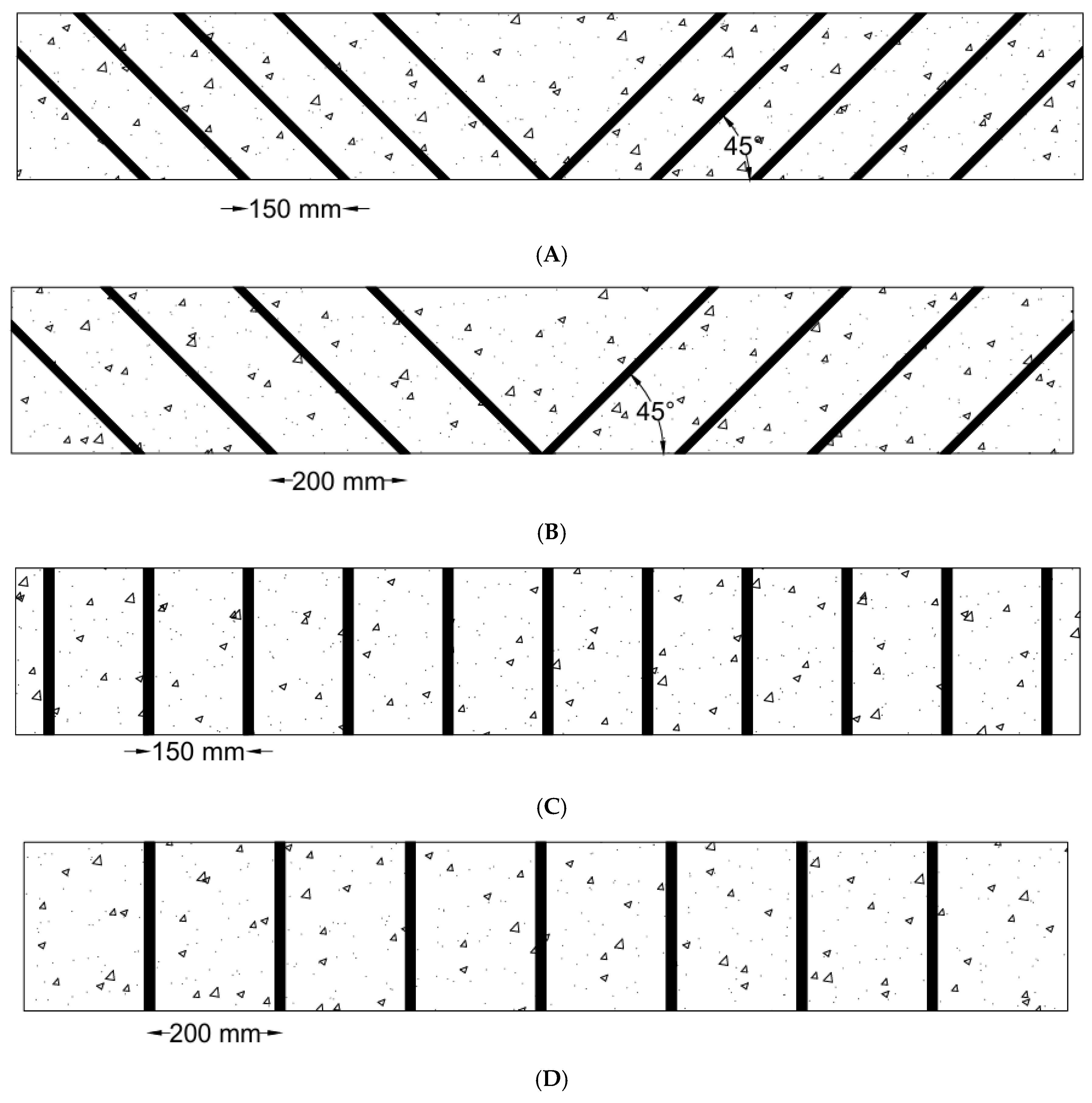
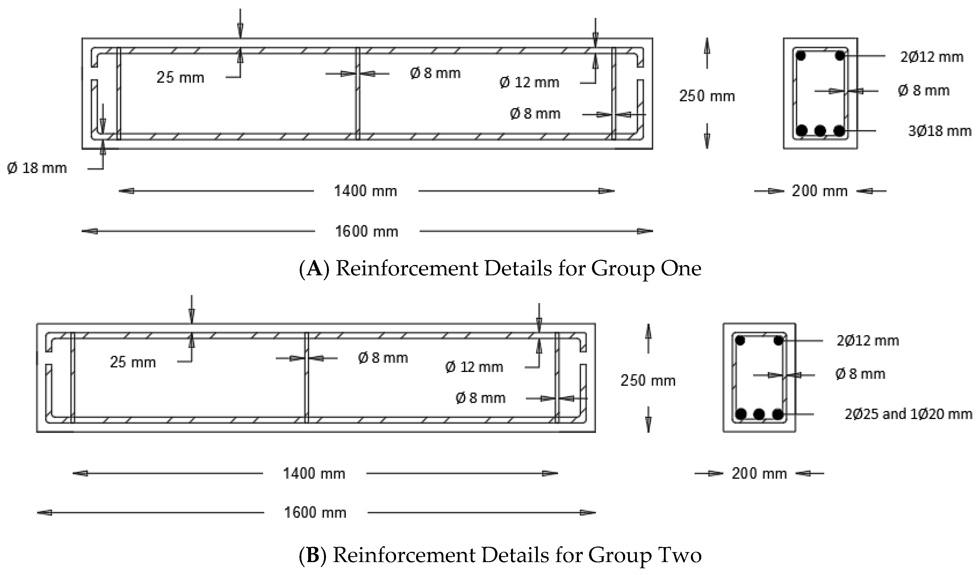
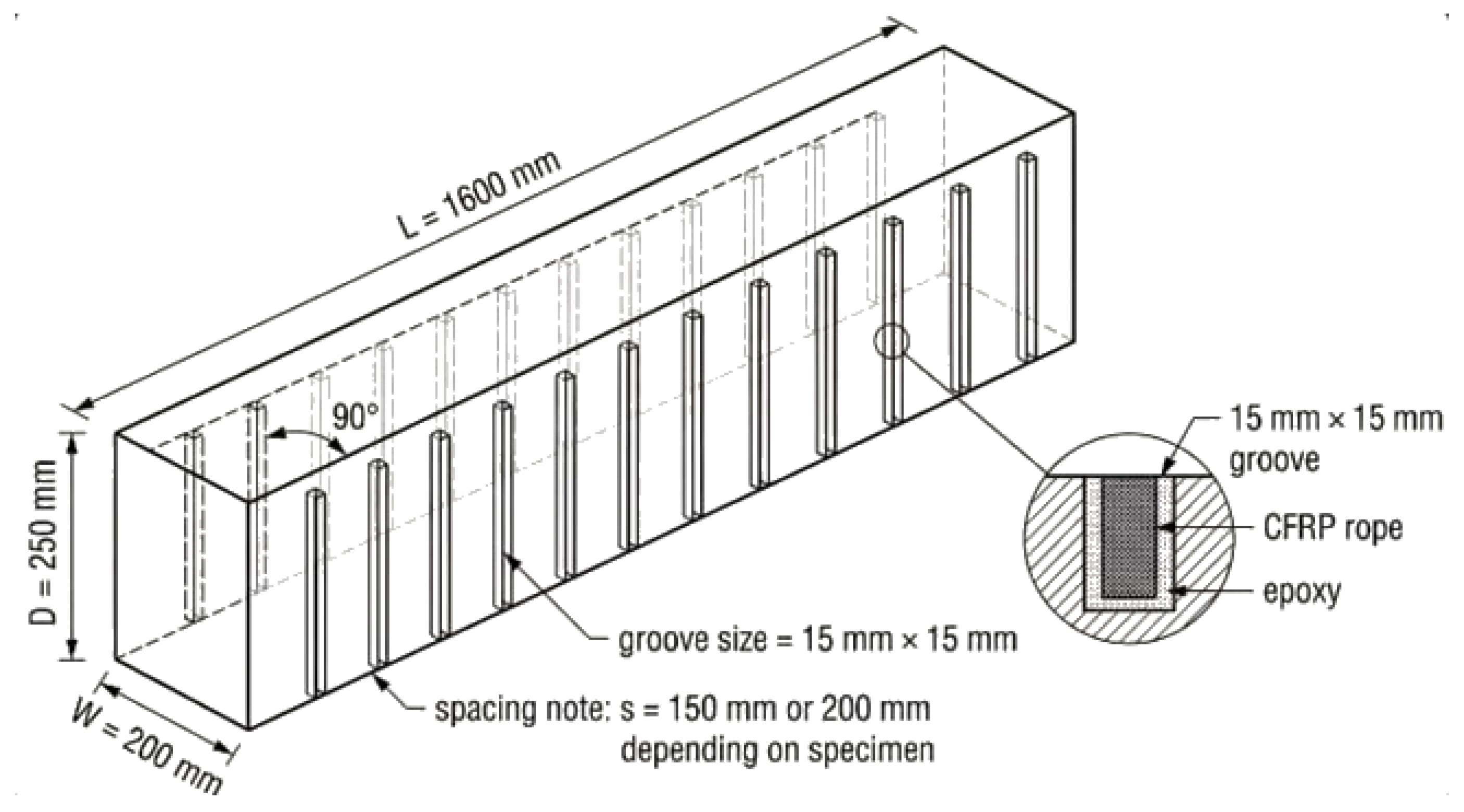
Twelve reinforced concrete (RC) beams were tested. Each beam was cast using a concrete mix of different compressive strengths: normal and high. The beams were designed to be 200 mm wide × 250 mm deep × 1600 mm long, as shown in Figure 1. The beams were divided into two groups of six. All beams were shear strengthened using different configurations of carbon fiber-reinforced polymer (CFRP) ropes, as shown in Table 1. The CFRP rope orientations of 45° and 90° were selected to represent two distinct and practically relevant shear strengthening configurations. The 45° orientation was chosen because it is approximately aligned with the direction of diagonal shear cracks and principal tensile stresses typically formed in reinforced concrete beams subjected to shear. The 90° orientation, on the other hand, represents a conventional vertical strengthening layout similar to the action of vertical stirrups and commonly adopted in practical shear strengthening applications. This selection allowed the direct comparison between inclined and vertical NSM CFRP strengthening schemes.
The beams were specifically intended to fail in shear before yielding the tensile reinforcement or crushing the concrete in compression. This allowed for concentration specifically on the shear behavior under controlled conditions and ensured that shear failure was the primary failure mode. Three stirrups were used to keep the longitudinal reinforcement aligned and to prevent localized failure at the supports. The stirrups were installed at specific locations in the beams: one was placed at mid-span, and two were placed at the support locations, as shown in Figure 1.
Table 1. Details of Test Specimens.
Group IDCompressive Strength Specimens
Designation
Strengthening SchemesFiber OrientationStrengthening Layout Based on Figure 2
Group
One
Normal Compressive Strength
(25 MPa)
NS-CUControl beam without exposure to heatN/AN/A
NS-CHControl beam exposed to heatN/AN/A
NS-150 mm-45°CFRP ropes spaced at 150 mm over the span length45°(A)
NS-200 mm-45°CFRP ropes spaced at 200 mm over the span length45°(B)
NS-150 mm-90° CFRP ropes spaced at 150 mm over the span length90°(C)
NS-200 mm-90°CFRP ropes spaced at 200 mm over the span length90°(D)
Group
Two
High Compressive Strength
(60 MPa)
HS-CUControl beam without exposure to heatN/AN/A
HS-CHControl beam exposed to heatN/AN/A
HS-150 mm-45°CFRP ropes spaced at 150 mm over the span length45°(A)
HS-200 mm-45°CFRP ropes spaced at 200 mm over the span length45°(B)
HS-150 mm-90° CFRP ropes spaced at 150 mm over the span length90°(C)
HS-200 mm-90°CFRP ropes spaced at 200 mm over the span length90°(D)

2.2. Materials

2.2.1. Concrete

The beam specimens were cast using ready-mixed concrete with two target compressive strength classes of 25 MPa and 60 MPa in order to investigate the influence of concrete strength (normal-strength and high-strength concrete) on the shear behavior of the beams and on the effectiveness of the NSM CFRP rope strengthening system. The mixes were supplied as ready-mixed concrete, and the actual compressive strengths were determined experimentally using companion cylinder specimens tested at 7 and 28 days. The average 28-day compressive strengths were 25.1 MPa and 60.4 MPa for the mixes targeted at 25 MPa and 60 MPa, respectively. A summary of the concrete mix proportions provided by the supplier is presented in Table 2.

2.2.2. Steel Reinforcement

The longitudinal reinforcement consisted of high-yield-strength deformed (HYSD) bars, sized 18 mm, 20 mm, and 25 mm, that met the specification of Grade 60 (fy = 420 MPa or 60 ksi). The transverse reinforcement (stirrups) consisted of 8.0 mm diameter steel bars meeting the specification of Grade 40 (fy = 280 MPa or 40 ksi).

2.2.3. CFRP Ropes

SikaWrap FX-50 C is a unidirectional carbon fiber rope within a plastic sheath. It was developed for fiber anchorage systems for SikaWrap textile reinforcement and applications with NSM strengthening techniques. SikaWrap FX-50 C is also suitable for use in warm or tropical weather conditions. A complete summary of the technical properties of the CFRP rope provided by the manufacturer is presented in Table 3. The reported properties correspond to the dry carbon fibers as specified in the manufacturer’s technical data sheet.
In this study, two epoxy adhesives, Sikadur®-330 and Sikadur®-52 LP, are provided by Sika Company, Amman, Jordan. Table 4 presents the mechanical and physical characteristics of these two materials. Sikadur®-330 is a two-component structural adhesive, with Part A and Part B (hardener). The adhesive consists of component A (white resin) and component B (gray hardener). Sikadur®-330 is mixed in accordance with a weight-to-volume ratio of 4:1.

2.3. Heating Process

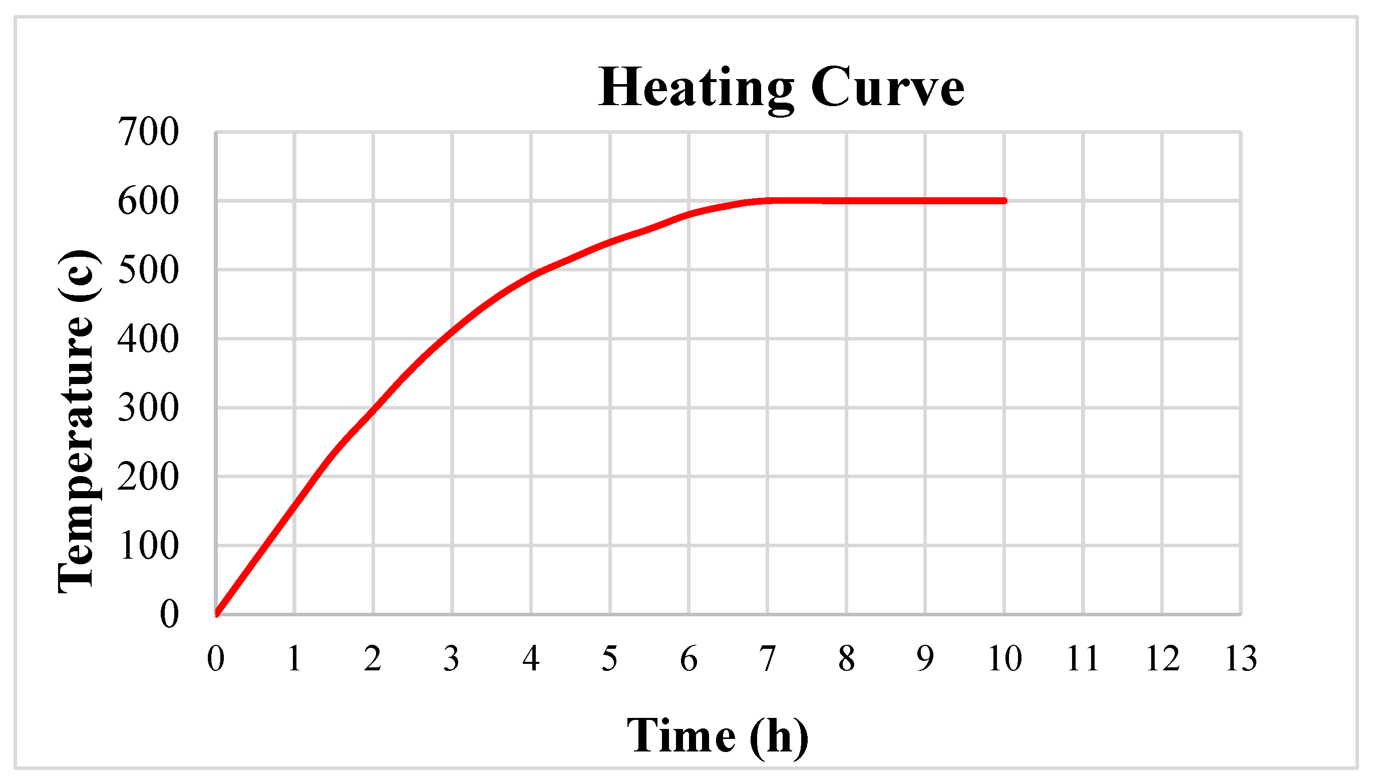
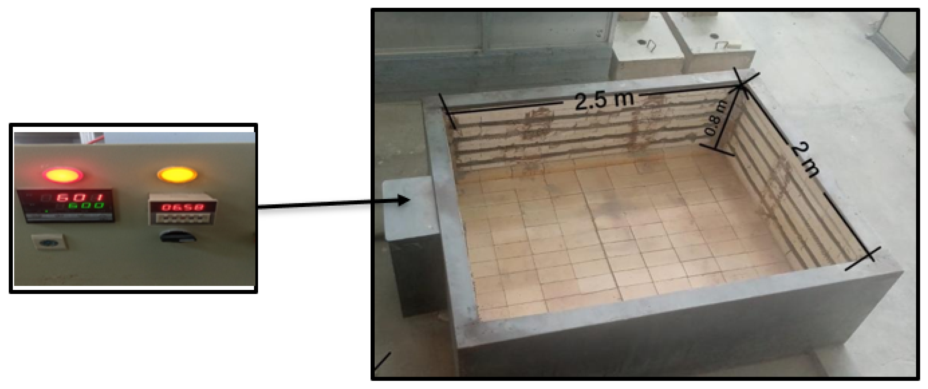
Before the strengthening process, ten beams were exposed to elevated temperature to simulate fire-induced damage. The specimens were placed inside a high-temperature furnace with internal dimensions of 2 m × 2.5 m × 0.8 m and covered with a steel slab measuring 2.2 m × 2.7 m. The furnace temperature was gradually increased following a controlled heating regime until reaching a peak temperature of 600 °C, as illustrated in Figure 3. After reaching this temperature, the specimens were maintained at 600 °C for a period of 3 h to ensure sufficient thermal exposure. The temperature inside the furnace was monitored using a digital thermometer installed within the furnace chamber, and the readings were continuously recorded using a digital temperature reader as described in Figure 4.

2.4. Installation of NSM-CFRP Ropes

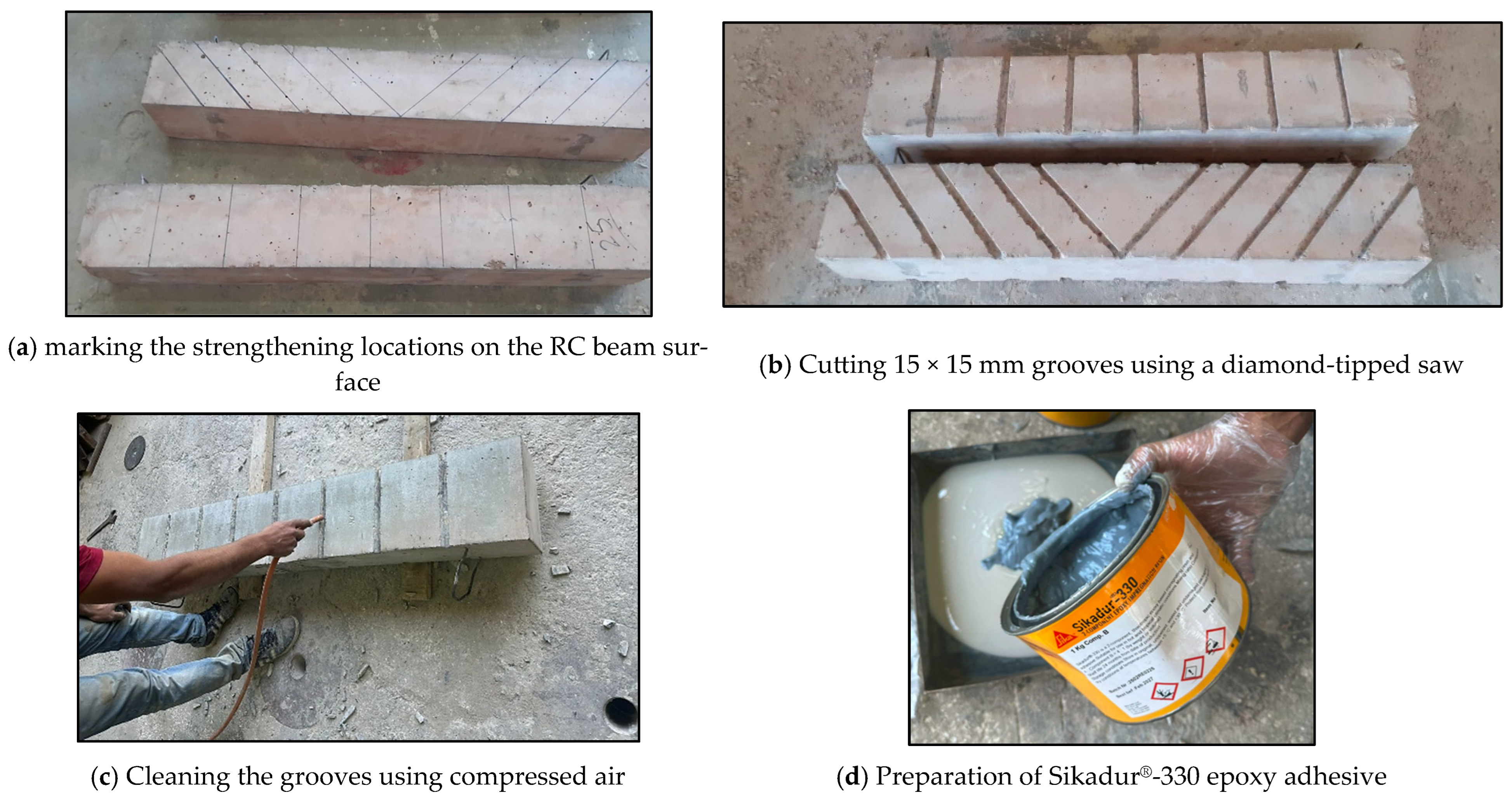
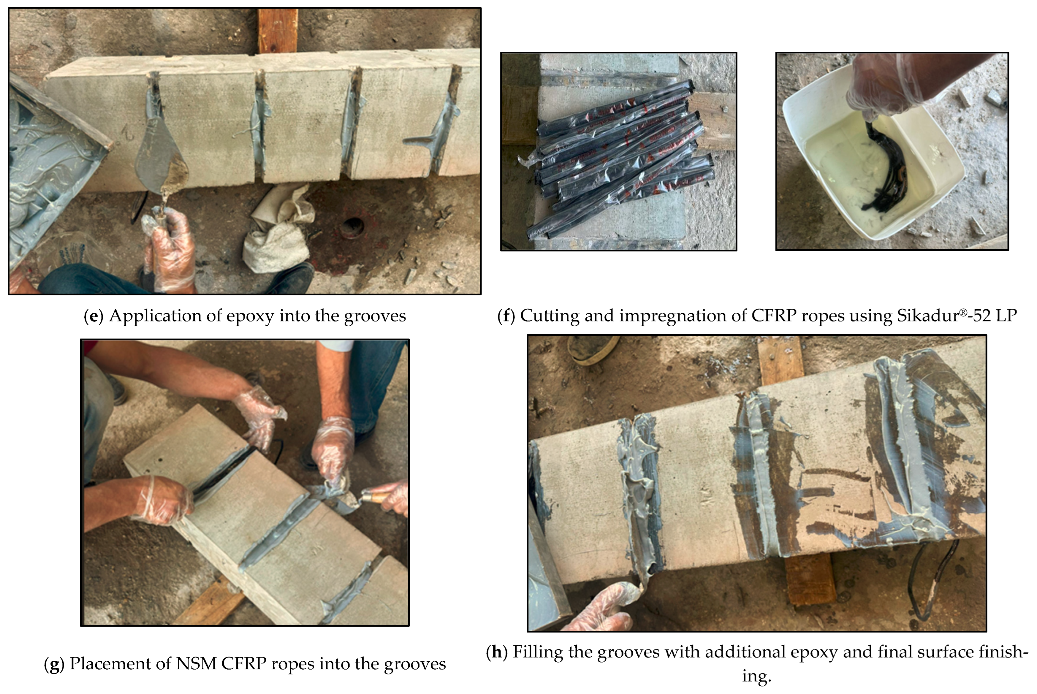
The strengthening of the RC beams was performed using the NSM technique with CFRP ropes installed along the shear span on the two vertical sides of the beams. The strengthening locations were first marked on the concrete surface, after which rectangular grooves with dimensions of approximately 15 mm × 15 mm were cut using a diamond-tipped saw. Since the CFRP ropes were installed inside the grooves using the NSM technique, rounding of the beam edges was not required. The grooves were then thoroughly cleaned using compressed air to remove dust and loose particles to ensure adequate bonding between the CFRP reinforcement and the concrete substrate. The epoxy adhesive Sikadur®-330 was prepared according to the manufacturer’s recommended mixing ratio until a homogeneous mixture was obtained. A layer of epoxy was applied to the bottom and sides of the grooves before inserting the CFRP ropes. Prior to installation, the ropes were cut to the required length and saturated using Sikadur®-52 LP to ensure proper impregnation of the fibers. The saturated ropes were then carefully pressed into the grooves to ensure full embedment and continuous contact with the adhesive layer. After positioning the ropes, additional epoxy was applied to completely fill the grooves and encapsulate the CFRP reinforcement. The surface was then leveled flush with the surrounding concrete using a steel trowel. In this study, the CFRP ropes were applied on two sides of the beam, and no mechanical anchorage or overlap length was used, as the ropes were fully bonded along the groove length according to the NSM strengthening technique. The main stages of the NSM CFRP rope installation process are illustrated in Figure 5.Grooving layout for NSM CFRP strengthening are presented in Figure 6.

2.5. Test Setup

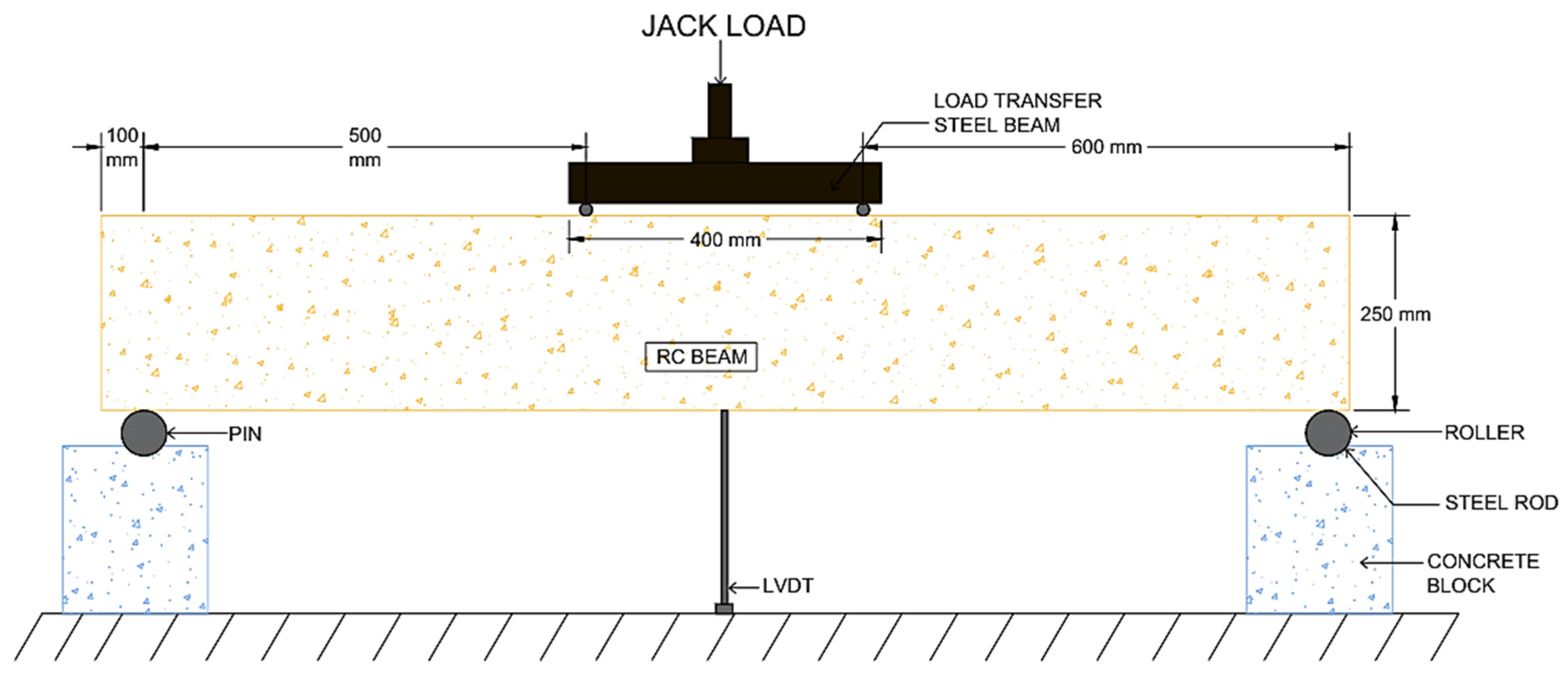
Twelve RC beam specimens were tested under four-point loading at the Structural Laboratory of the University of Jordan. Each beam was simply supported at one end with a steel roller and a steel pin at the other end. The loading system accommodated two concentrated loads, spaced 400 mm apart. The concentrated loads were positioned such that a constant shear span-to-depth ratio of 2.22 was maintained, with the applied loads located 500 mm from the center of the nearest support. A hydraulic jack, rated for a maximum capacity of 750 kN, was utilized for load application. The beams were tested under monotonic four-point loading using load control at a constant loading rate of 10 kN/min until failure. The mid-span deflection was measured through the installation of a Linear Variable Displacement Transducer (LVDT) located at the bottom of each beam, with load and displacement monitored through an electronic data acquisition system. The overall test setup, as well as the LVDT location, is shown in Figure 7.

2.6. Test Results

2.6.1. Group One Results

Table 5 summarizes the key performance metrics and improvement ratios for the repaired beams.
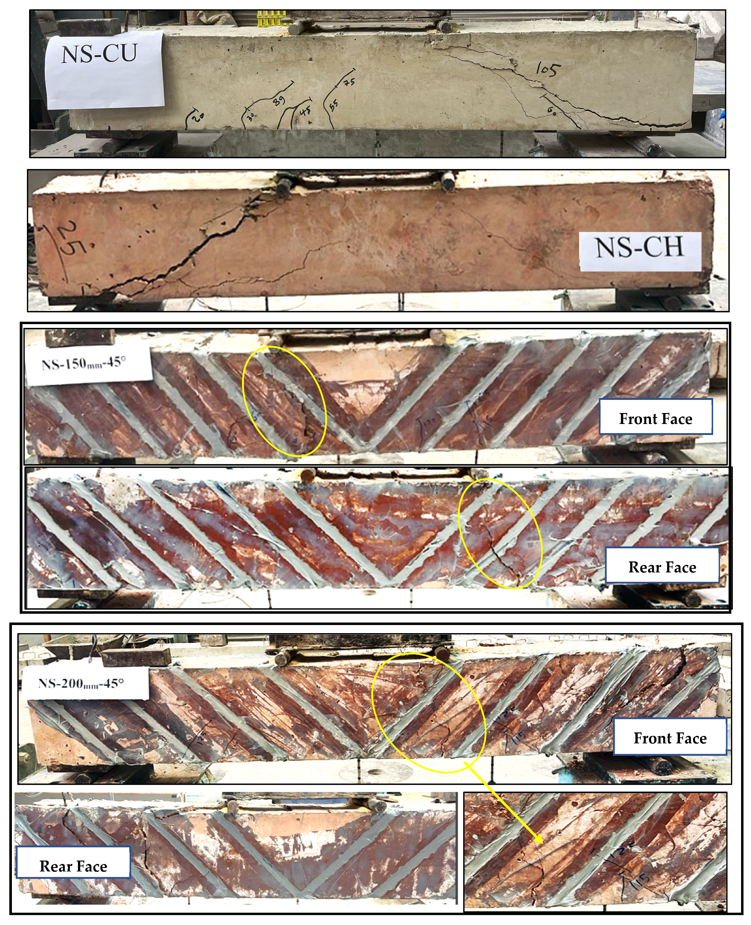
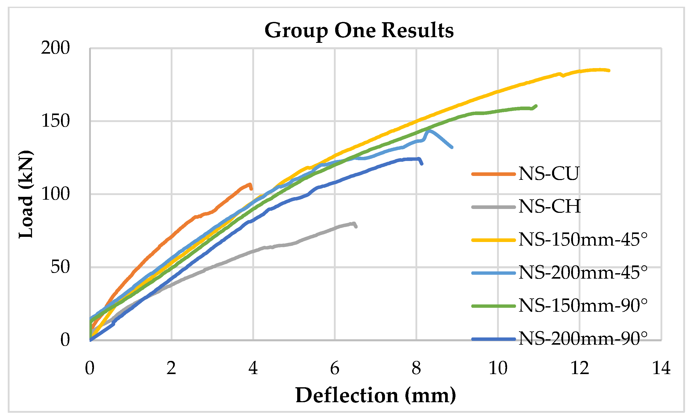
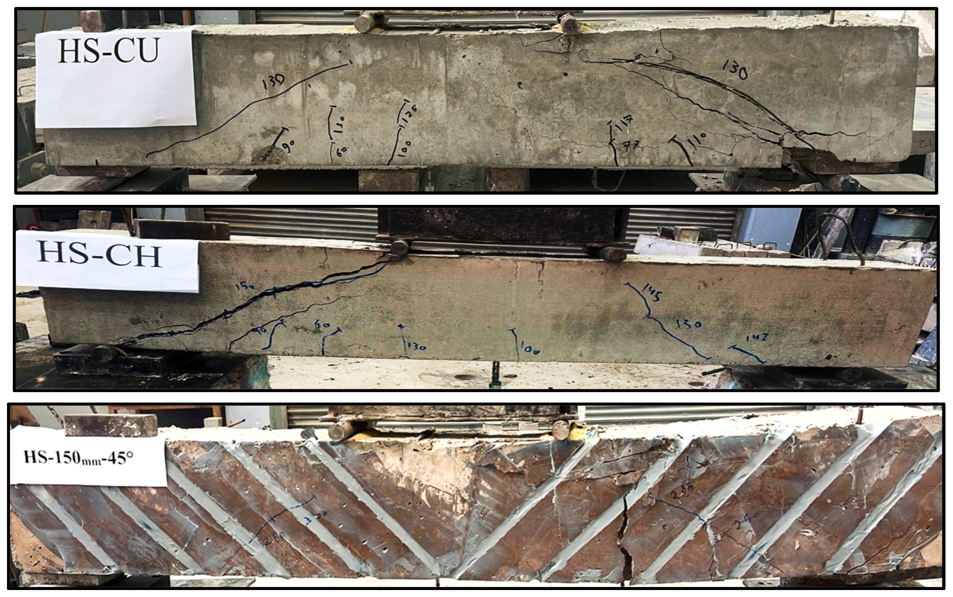
The results of Group One show the effects of thermal exposure on the reinforced concrete (RC) beams and their recovery through CFRP rope strengthening. The control beam that was not thermally exposed (NS-CU) exhibited flexural and shear cracks at 20 kN and 55 kN, respectively, and reached an ultimate load of 106 kN with a displacement of 3.9 mm. The failure mode for this beam was governed by a shear failure (SF) mechanism. The control beam that was thermally exposed (NS-CH) experienced a significant reduction in capacity, with ultimate strength reduced to 79 kN (i.e., a 25% reduction compared to NS-CU). The first flexural crack developed much earlier, at 30 kN compared to 20 kN for the NS-CU beam, while the first shear crack occurred at 23 kN compared to 55 kN for the NS-CU beam. The ultimate displacement of this beam increased to 6.5 mm, indicating improved ductility; however, the stiffness and load-carrying capacity of the beam were clearly diminished, and failure occurred in a shear mode.
The implementation of CFRP ropes was extremely effective in reducing the negative influence of thermal exposure. The specimen with ropes spaced 150 mm apart and installed at 45° (NS-150 mm-45°) exhibited the greatest enhancement, with flexural and shear cracks sustained until 140 kN and 110 kN, respectively. It also achieved an ultimate load of 186 kN, which corresponds to a 135% increase compared to NS-CH and a 75% increase relative to NS-CU, along with exhibiting the greatest ductility (12 mm). All specimen failures occurred in a combined shear–flexural (S–F) mode. These observations demonstrate that closely spaced inclined reinforcement is more efficient in restoring and improving the overall structural performance of heat-damaged beams.
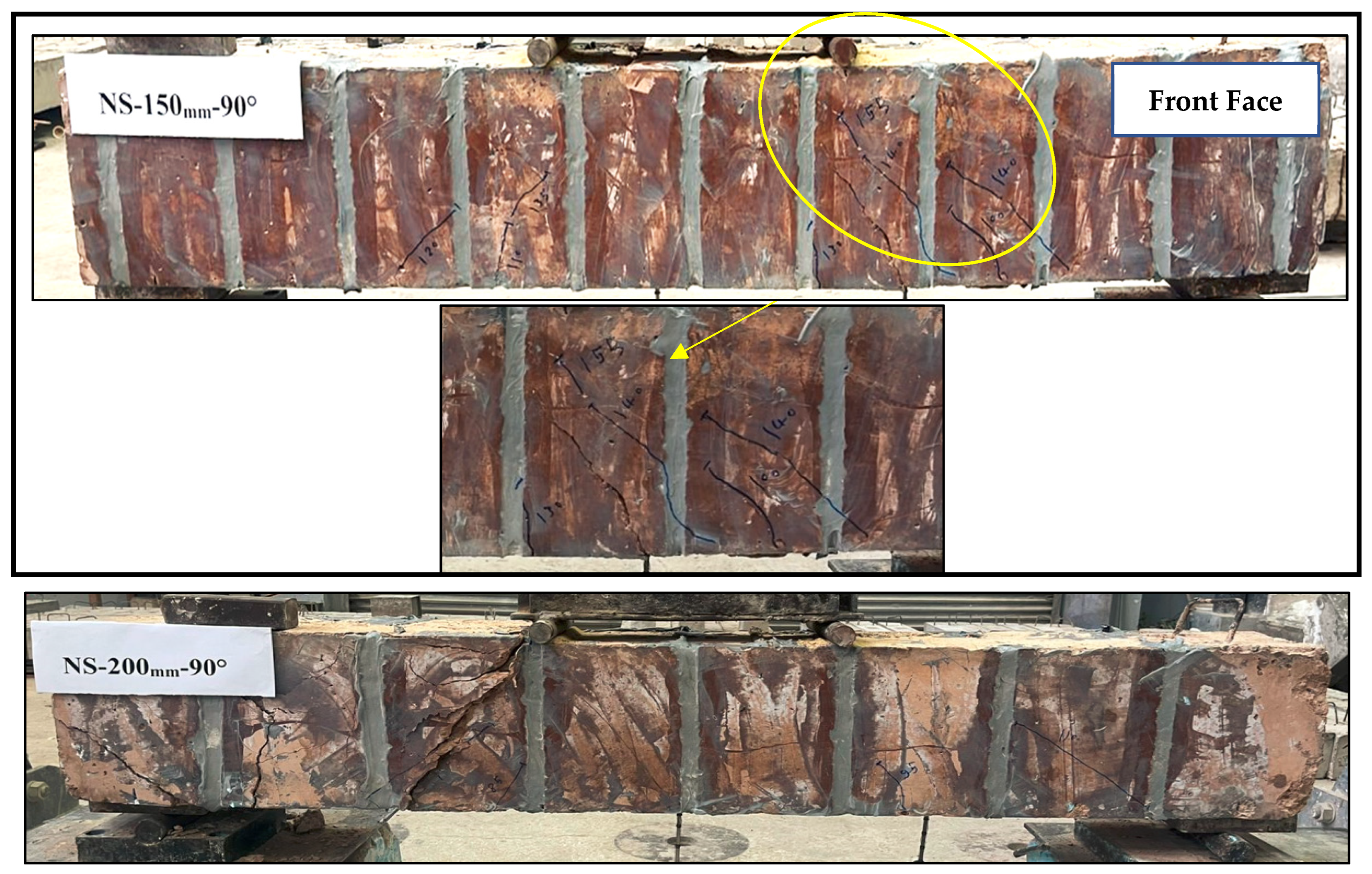
The NS-200 mm-45° specimen, with 200 mm rope spacing and a 45° angle of inclination, recorded significant improvements, with an ultimate load of 143 kN, corresponding to an 81% increase over NS-CH. The ropes configuration in this beam was less efficient than the beam NS-150 mm-45°, as indicated by lower cracking loads and a displacement of 8.2 mm. As the shear resistance improved, flexural demands became governing, resulting in a flexural failure (FF) mode. Vertically anchored ropes provided some improvements, but not to the same extent as inclined configurations. The NS-150 mm-90° specimen achieved an ultimate load of 160 kN, equivalent to a 102% improvement over NS-CH, with a displacement of 10.9 mm, and failed in shear, while the NS-200 mm-90° specimen reached an ultimate load of 124 kN, representing a 57% improvement over NS-CH, with a displacement of 8.1 mm, and also failed in shear.
The higher load corresponding to the first flexural crack observed in the strengthened specimens can be attributed to the increase in the overall stiffness of the beam section due to the presence of the NSM CFRP ropes. The embedded CFRP reinforcement contributes to reducing tensile stresses in the concrete, which delays the initiation of flexural cracking compared to the control specimens.
Although the inclined (45°) configuration is mechanically more aligned with diagonal shear cracking, the experimental results show that the load–displacement responses of the 45° and 90° strengthened beams remain relatively similar. This behavior can be attributed to the prior thermal exposure of the specimens to 600 °C, which caused significant deterioration in the concrete matrix. Under these conditions, the structural response becomes strongly influenced by the residual properties of the thermally damaged concrete, reducing the extent to which CFRP orientation alone can influence the overall shear behavior.
In summary, the findings show that thermal exposure results in significant decreases in the strength and stiffness of unstrengthened reinforced concrete beams. The use of CFRP rope strengthening was highly effective in mitigating most of the negative effects of thermal exposure and, in several instances, restoring a greater capacity than the unheated control beam. These results indicate the important influence of reinforcement configuration, with ropes spaced at 150 mm and oriented at a 45° angle representing the most effective strengthening solution, providing the greatest gains in load-carrying capacity and ductility. Increasing the spacing to 200 mm diminished the overall strengthening efficiency. Vertical orientation, although beneficial, resulted in consistently lower load-carrying capacity and ductility compared to inclined configurations. Failure modes and crack patterns are shown in Figure 8, while load–deflection curves for Group One results are presented in Figure 9.

2.6.2. Group Two Results

Table 6 summarizes the key performance metrics and improvement ratios for the repaired beams.
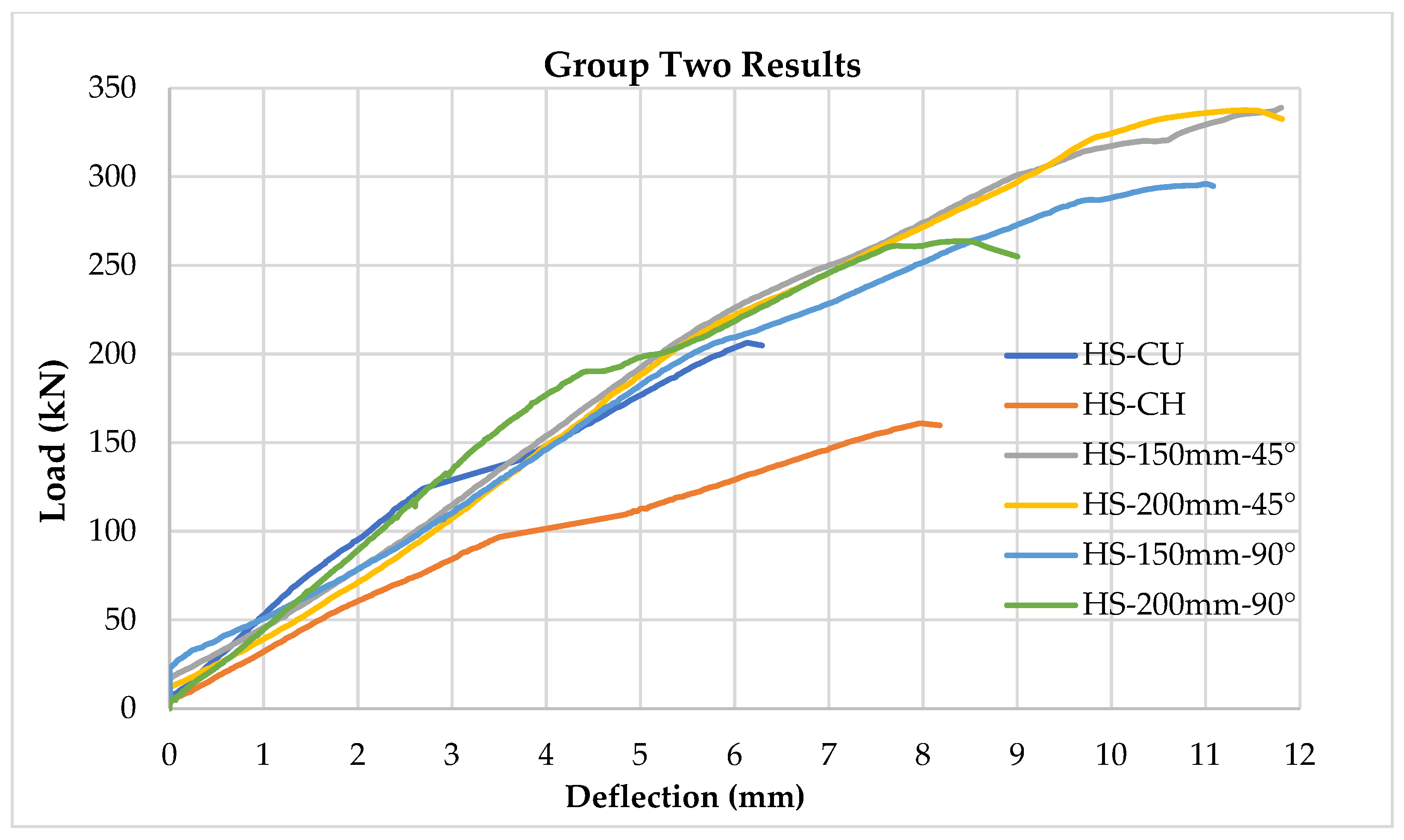
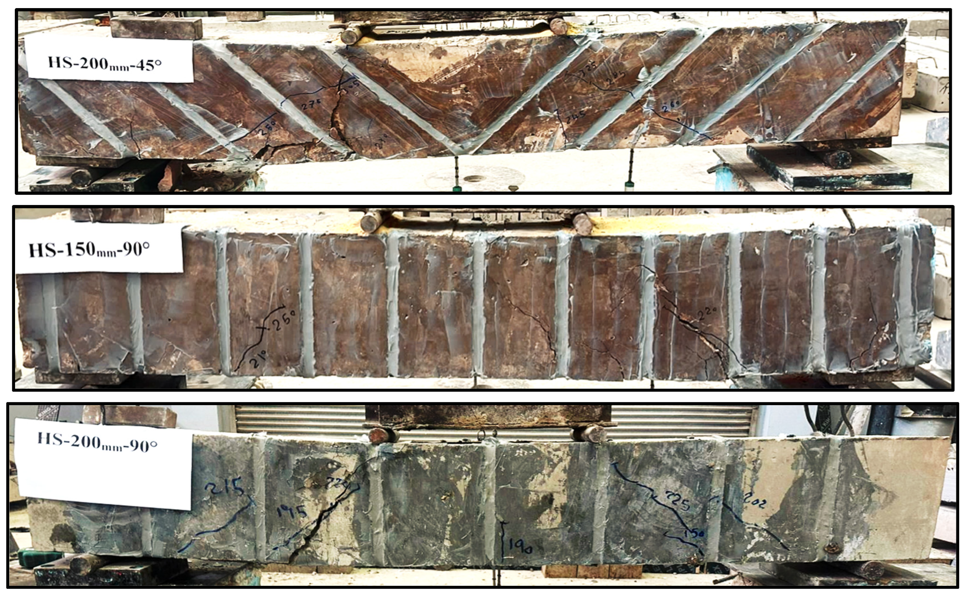
For Group Two, high-strength concrete, the ultimate loads for the unstrengthened reference beams HS-CU and HS-CH were 206 kN and 160 kN, respectively. Significant strength gains were achieved with 45° and 90° rope strengthening. The HS-150 mm-45° specimen reached 339 kN, which represents a 64.5% and 111.8% gain over HS-CU and HS-CH, respectively. The HS-200 mm-45° specimen reached a load of 337 kN, providing a gain of 63.6% and 110.6% over HS-CU and HS-CH, respectively. The beams strengthened with ropes at 90° also gained c apacity; however, to a lesser extent. The HS-150 mm-90° specimen attained a load of 296 kN (43.7% and 85.0% gains), and the HS-200 mm-90° specimen attained 263 kN (27.7% and 64.4% gains over HS-CU and HS-CH, respectively).
The specimens that were repaired with ropes also exhibited increased deformation capacity. The beam HS-150 mm-45° showed the highest ultimate displacement of 11.8 mm. The results indicate that the load capacity and ductility were influenced by the spacing and orientation of the ropes for the tests completed in this phase. The change in failure modes (the control beams failed in shear, while the strengthened beams exhibited shear or shear–flexural failure modes) indicates that the CFRP ropes contributed significantly to the shear capacity of the beams. Overall, the 45° rope configuration was more effective than the vertical rope configuration in mobilizing composite action and provided improved post-cracking performance. Failure modes and crack patterns are shown in Figure 10, while load–deflection relationships for Group Two results are presented in Figure 11.

2.6.3. Effect of Experimental Parameters

Concrete Compressive Strength
Under all variable configurations, high-strength concrete beams showed greater ultimate loads than normal-strength concrete beams, regardless of capacity restrictions put in place for beam construction (controlled by variables). For unstrengthened beams, HSC control beams (HS-CU and HS-CH) had ultimate loads that exceeded the capacities of NSC control beams (NS-CU and NS-CH) by roughly 35–40%. This difference in performance validated the notion that higher compressive strength concrete naturally provides greater capacity with respect to flexural and shear failure. The capacity performance difference consistently remained sustained in the strengthened beams, indicating that while CFRP rope confinement improved shear capacity for both categories, the base concrete strength proved to be a controlling factor contributing to the overall capacity of the beams.
CFRP Rope Spacing
Changing the rope spacing from 200 mm to 150 mm improved the ductility and load capacity of both concrete mix grades. In the case of the 45° orientation, for instance, the reduction in spacing led to additional strength increase of 5–10%. Reduced spacing led to improved crack control and enhanced stress transfer between the concrete and the rope, which postponed diagonal cracking and reduced stiffness degradation. This effect was especially noticeable in the NSC beams, where rope confinement increased the compressive strength of a weaker matrix by more than 25 MPa. However, rope spacing had no discernible effect on the strengthening when the compressive strength of the HSC mix reached approximately 60 MPa. When compared to NSC beams, the spacing effect was almost insignificant for both ductility and load capacity.
CFRP Rope Orientation
The orientation of the rope was identified as an important factor in shear contribution. The 45° inclination consistently outperformed the 90° vertical arrangement in terms of ultimate load and deformation capacity. In the NSC beams, the 45° orientation provided capacity increases of up to 96% over control beams, compared to increases of 54–65% for the 90° orientation. In the HSC beams, the 45° orientation improved the load capacity of beam specimens by 64–112% relative to the control beams, compared to 28–85% for vertically oriented ropes. The increased performance of the inclined orientations can largely be attributed to their alignment with the principal tensile stress trajectories in the shear span, allowing for more effective crack bridging and shear transfer.

3. Numerical Analysis

3.1. Finite Element Method (FEM)

FEM is a general numerical approach that can solve an extremely broad range of engineering problems, from relatively simple linear calculation to extremely complex nonlinear simulation. The finite element model of the RC beams was created using the ABAQUS/CAE 2020 package. The overall length of the beams was 1600 mm and their cross-section measured 200 × 250 mm. The concrete was modeled as a three-dimensional solid while both the steel reinforcement and CFRP ropes were modeled as one-dimensional elements. The experimental boundary conditions were replicated by explicitly modeling the loading and support plates in the software. Once the material properties of each of the components were defined, the model was assembled. Each of the simulations was run under one static analysis (the time step was fixed at 1 s) for all models in order to reduce excess computational requirements. Tie constraints were used to ensure complete interaction between all components, except at the interface between the steel and concrete components which were modeled as an embedded region, with perfect bond behavior assumed to apply. This modeling assumption simplifies the interaction between the strengthening system and the concrete substrate and does not explicitly account for bond–slip effects. However, no CFRP rope debonding, pull-out, or concrete cover splitting was observed during the experimental tests, which supports the validity of the adopted assumption for reproducing the global structural response of the beams.
In the finite element model, the effect of elevated temperature was represented by considering the post-heating condition of the beams after exposure to 600 °C. The influence of temperature was introduced by modifying the material properties of concrete and reinforcing steel according to EN 1994-1-2 [30], including the reduction in modulus of elasticity and strength parameters to represent the thermally damaged condition of the specimens.
To simulate the loading applied to the concrete beam during the experimental tests, a displacement-controlled loading was selected to gradually increase the deflection until the peak load was achieved and to prevent numerical instability once the peak load was exceeded. A mesh sensitivity analysis was conducted to evaluate the influence of element size on the numerical results. Mesh sizes of 20 mm, 30 mm, and 40 mm were examined, and the comparison of the load–displacement responses showed only minor differences. The variation in the predicted ultimate load was less than 3%, indicating that the numerical results are not significantly affected by further mesh refinement. Therefore, a uniform mesh size of 30 mm was adopted in the final model as a balance between numerical accuracy and computational efficiency. The concrete beams were meshed with uniform 30 mm mesh sizes; hexahedral elements were assigned to beams with vertical CFRP strengthening, while tetrahedral elements were used to model those beams with inclined strengthening to better accommodate the inclined geometry. For the inclined strengthening configuration, the geometry of the grooves makes it difficult to maintain a structured hexahedral mesh; therefore, tetrahedral elements were adopted in these regions to preserve mesh quality. This mesh sensitivity assessment also indicates that the potential mesh dependency associated with the CDP softening formulation does not significantly influence the global structural response predicted by the model. Monitoring of load and mid-span deflection through the use of defined field outputs and historical results were created.

3.1.1. Beam Modeling

In this module, geometric modeling for each individual component was carried out by defining dimensions and their shapes directly. For realistically simulating experimental tests performed in the laboratory, five components were assigned in the model: load plate, steel reinforcement bars, concrete, support plates, and CFRP rope. Geometric characteristics and material characteristics assigned to each component are shown in detail in Table 7.

3.1.2. Materials

The nonlinear behavior of concrete was simulated using the Concrete Damaged Plasticity (CDP) model available in ABAQUS [31]. The CDP model is a continuum-based plasticity formulation capable of representing the inelastic behavior of quasi-brittle materials such as concrete under both tension and compression. The model accounts for stiffness degradation due to damage and allows the representation of plastic strains in compression and cracking behavior in tension.
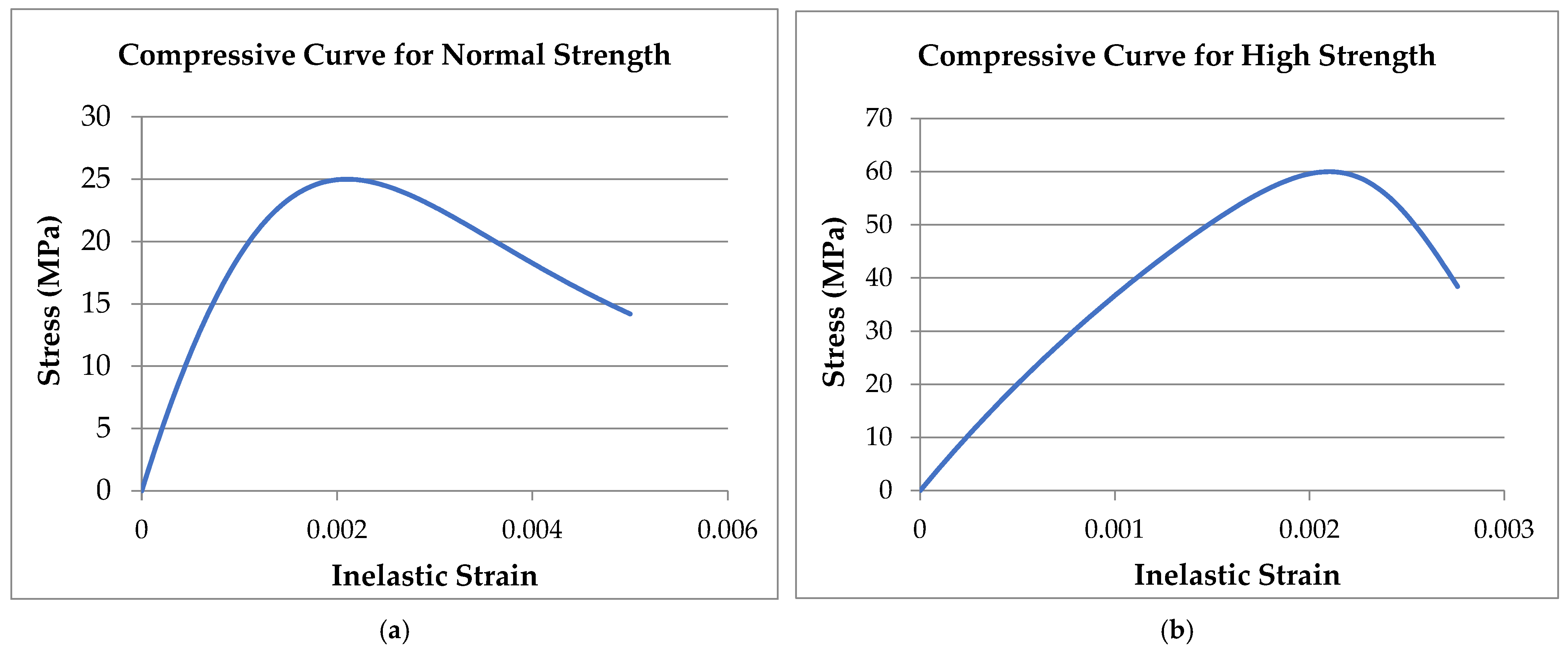
The compressive stress–strain relationship of concrete was defined using the normalized stress–strain equation proposed by Tsai [32]. This formulation provides a smooth representation of the nonlinear compressive behavior of concrete and is commonly used to generate input curves for numerical modeling.
The normalized stress–strain relationship is expressed as
y = n x 1 + n r r 1 x + x r r 1
where  x = ε c ε c , y = f c f c . The strain at the compressive strength  f c  (in MPa) is taken as  ε c = f c 4690 + 260 f c    [33].  n  and  r  are parameters to control the shape of the stress–strain curve and are taken as  E c ε c f c  and  f c 5.2 1.9 , respectively [34].
The plasticity of concrete under tension is modeled based on Tsai’s equation as
y = n x 1 + n t r r 1 x + x r r 1      
where  x = ε t ε t 0 , y = f t f t 0 . n t  and  r  are parameters to control the shape of the curve. The strain at peak tensile strength  f t  is  ε t 0 .
  • Concrete
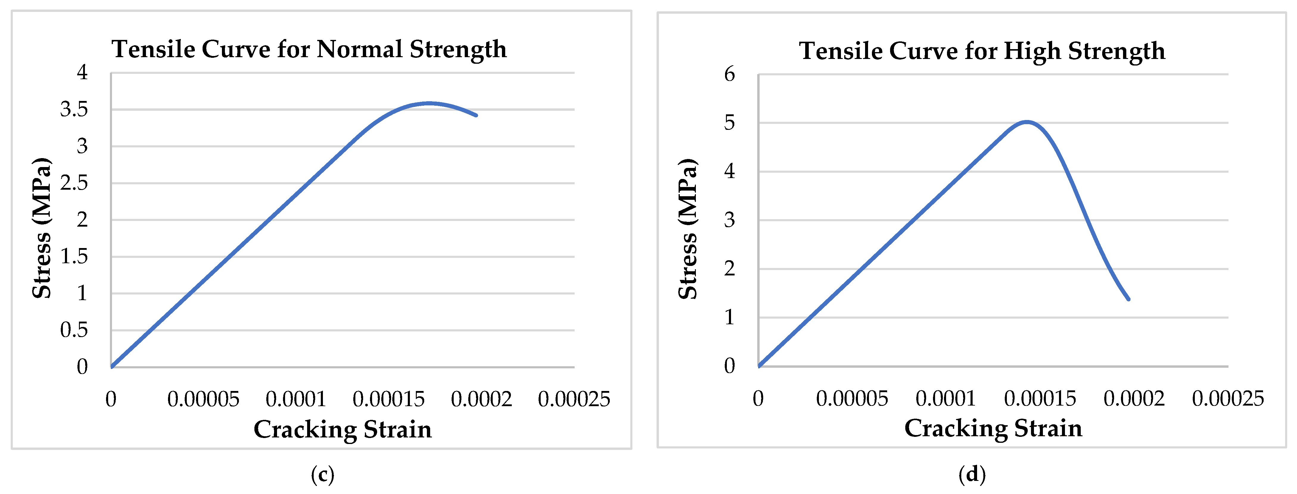
Tsai’s constitutive equations were employed to generate the stress–strain relationships used to represent the compressive behavior of both normal-strength (25 MPa) and high-strength (60 MPa) concrete used in the beams. The corresponding compression and tension stress–strain curves for both normal- and high-strength concrete are presented in Figure 12. The material properties adopted for the numerical model are summarized in Table 8.
The curves shown in Figure 12 were used to generate the input data required for the ABAQUS Concrete Damaged Plasticity (CDP) model, namely the stress–inelastic strain relationship for compression and the stress–cracking strain relationship for tension.
  • Concrete damage plasticity parameters
In this study, Concrete Damage Plasticity (CDP) model was used in the simulation of nonlinear concrete behavior under various conditions of loading. Model parameters were selected on the basis of commonly accepted values in the literature to ensure realistic material modeling. The parameters used are listed in Table 9.
  • Concrete Damage Parameter
Mechanical load-induced deterioration of concrete stiffness and strength is usually characterized by the compression and tension damage parameters, dc and dt, respectively. The two parameters, ranging from 0 to 1, quantify the extent of deterioration of the material: the value of 0 characterizes the undamaged state of the material, and the value of 1 represents loss of load-carrying capacity. According to the ABAQUS User’s Manual [31], these scalar damage variables enable accurate depiction of concrete failure mechanisms like tensile cracking and compressive crushing. Several formulations have been proposed in the literature for modeling the evolution of these damage parameters for uniaxial stress states. In the present work, the following equations were employed to simulate the evolution of tensile and compressive damage in concrete. The damage variables were calculated directly from the stress values obtained from the compressive and tensile stress–strain curves used in the CDP model. These relationships correspond to the descending branches of the stress–strain curves and were used to define the damage evolution associated with stiffness degradation in compression and tension.
dc = 1 σ c   f co dt = 1 σ t   f ct
where
  • σ c : Concrete compressive stress along the descending stress–strain curve.
  • f co: Concrete compressive stress at the peak point.
  • σ  t: Concrete tensile stress along the descending stress–strain curve.
  •   f ct: Concrete tensile stress at the peak point.

3.2. Validation Results

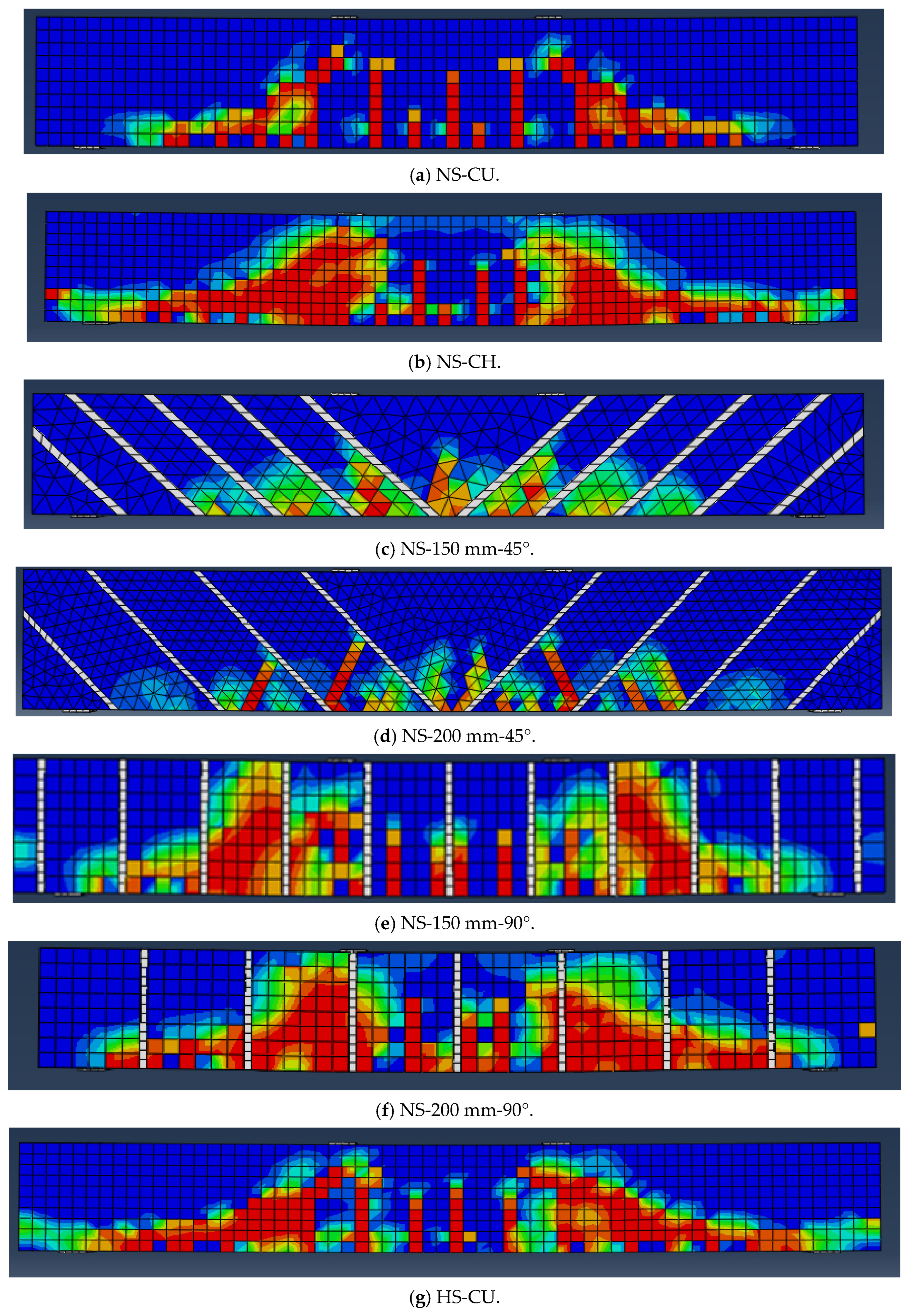
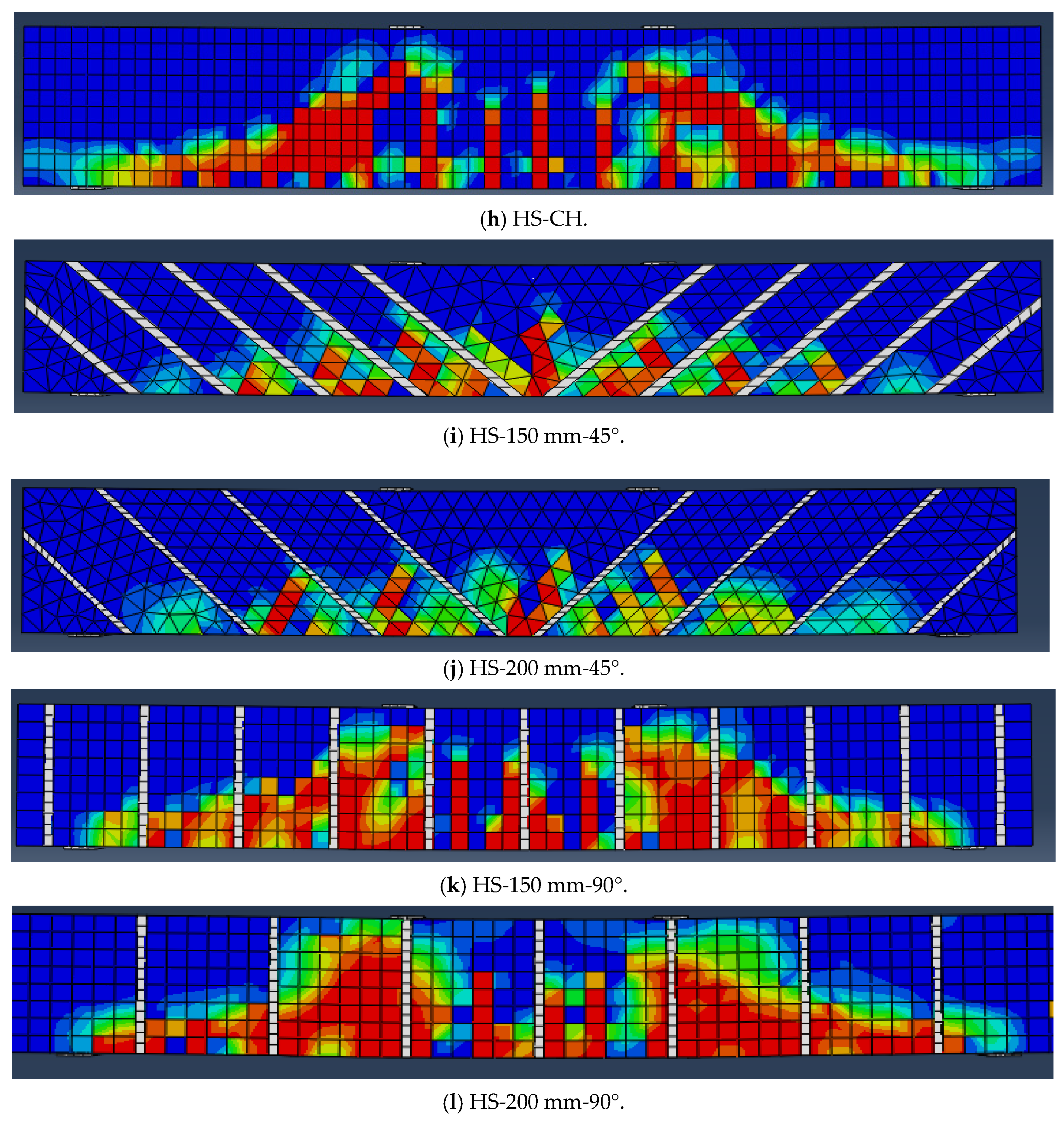
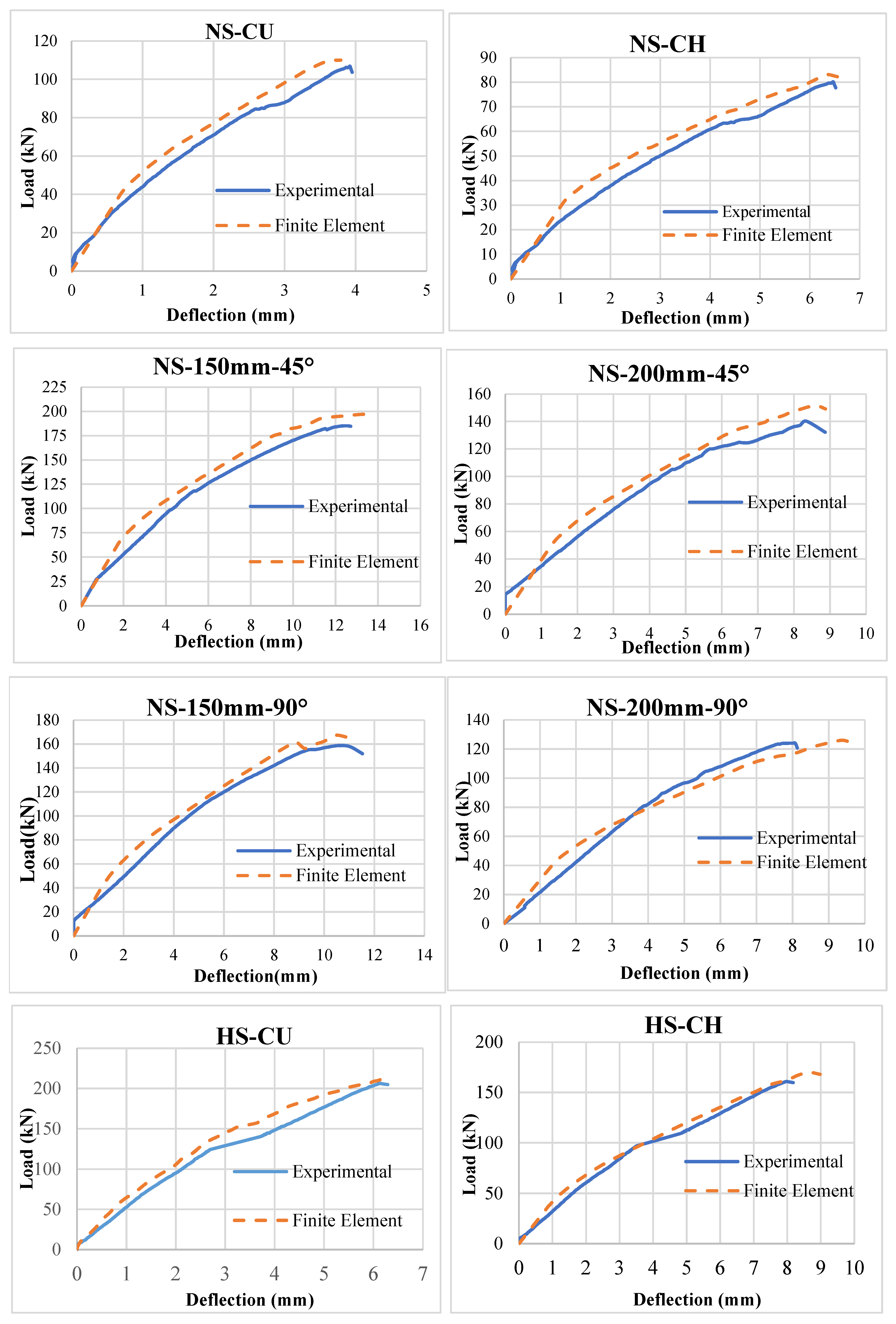
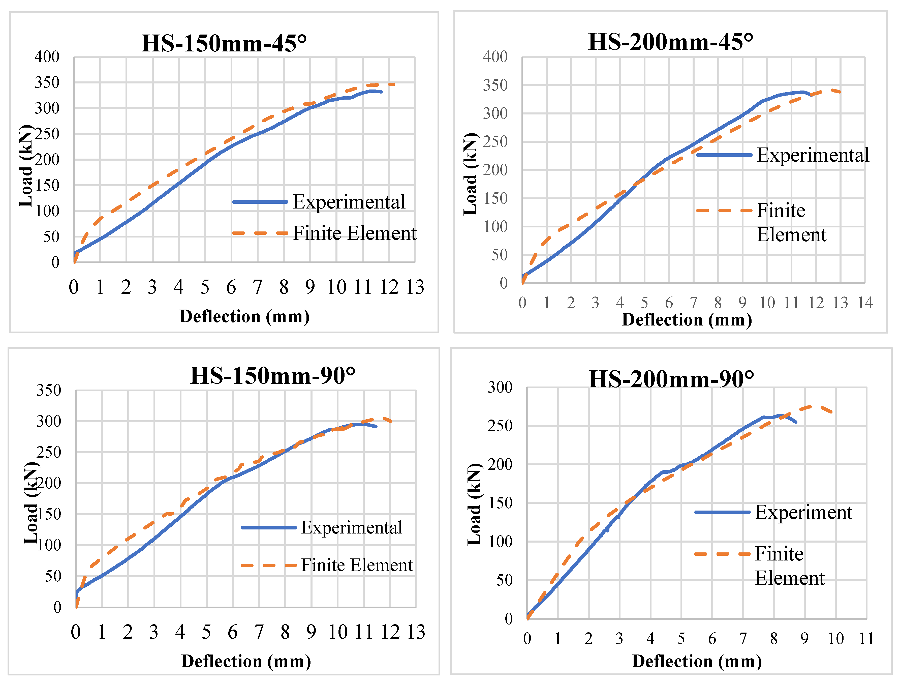
Comparison of results from the finite element model with the experimental results indicated a good correlation, hence establishing the accuracy and reliability of the numerical model in simulating the structural behavior of RC beams under various loading conditions. Detailed comparison between numerical and experimental results is shown in Table 10. Crack patterns and failure modes of FE models are shown in Figure 13. The ultimate load and the corresponding displacement showed good agreement between the experimental and numerical results. Figure 14 shows the load versus deflection comparison between experimental and finite element results.

4. Comparative Evaluation of Experimental Results with ACI 440.2R and Finite Element

Shear capacities of all tested beams with NSM CFRP-rope strengthening were experimentally verified against ACI 440.2R [35] provisions, as well as FE analysis. The verification of these separate predictive methods offers insight into how conservative or reliable each method may be, as well as how certain design parameters, specifically concrete strength, fiber placement orientation, and spacing of NSM CFRP, affect the predicted shear capacity. Interactions among these design parameters might affect the actual shear capacity of these beams and can have important design implications.
For the unstrengthened NSC beams (NS-CU and NS-CH), the range of relative differences between experimental and theoretical values was −1.1% to 14.4%, indicating that the ACI 440.2R recommendations are reasonably aligned, typically underestimating in some cases and overestimating in others. The range of relative differences for the HSC beams (HS-CU and HS-CH) was significantly larger, ranging from 34.3% to 50.4%, implying that the ACI 440 guidelines tend to underestimate the contribution of shear strength for high-strength concrete without FRP reinforcement. The theoretical predictions generally exhibited smaller relative differences for NSC than for HSC. In NSC beams, the smallest relative differences (2.0% to 5.0%) were observed with 150 mm FRP spacing, while these differences increased for spacing of 200 mm (−7.6% to −8.8%). FRP spacing was an important parameter and improved the accuracy of both absolute capacity and theoretical predictions; thus, reduced spacing or increased amounts of FRP provided higher diagonal shear resistance. For HSC beams, the percentage differences were smallest and closest to theoretical predictions with 150 mm FRP spacing, whereas the percentage differences for 200 mm spacing were significantly larger (11.9% to 31.1%). These results indicate that reduced spacing improves the contribution of the reinforcement to diagonal shear resistance and increases the predictability of the ACI 440.2R equations.
The effect of FRP orientation was also observed. Beams strengthened with FRP at 45° generally demonstrated better agreement between theoretical and experimental shear capacities than beams strengthened at a 90° orientation, demonstrating the more effective contribution of inclined fibers in resisting diagonal shear stresses. All tested beams exhibited increased shear capacity through the use of FRP strengthening, with the increases being more predictable in NSC beams than in HSC beams. Overall, ACI 440.2R recommendations for NSC beams were generally reliable, whereas predictions for HSC beams may require some adjustment, particularly as FRP spacing increases.
The FE analysis slightly overestimated the experimental results but showed consistent trends across all test specimens, with the estimated shear capacity ΔFE values averaging between 1.2% and 5.4% higher than the experimentally measured shear capacities. A summary of the comparison results is shown in Table 11.

5. Conclusions

This research evaluated the shear performance of twelve RC beams, six normal-strength and six high-strength, strengthened with NSM CFRP rope through various fiber orientations and CFRP spacing, with ten beams subjected to a temperature of 600 °C. All beams were subjected to shear loading and tested to determine the effects of the strengthening technique. The accuracy of Finite Element analysis was evaluated through comparison with ACI 440.2R predictions.
Key findings:
  • The experimental results demonstrate conclusively that the use of NSM CFRP significantly increases the shear capacities of all tested beams. Beams oriented with the fibers at 45° achieved higher shear capacities than those oriented at 90°. In addition, the absolute increase in shear capacity for HS beams was greater than that for NS beams, indicating that concrete strength has a significant impact on shear capacity. The effects of high temperature exposure were also evident, as exposure to 600 °C led to lower shear capacities compared to beams tested at room temperature.
  • Finite Element Analysis (FEA) predicted shear capacities that were slightly overestimated compared to the experimental results (by approximately 1% to 5%); however, the results were highly repeatable, exhibiting low scatter. The FEA showed reasonable agreement with observed trends related to fiber orientation, CFRP spacing, and temperature exposure.
  • The ACI 440.2R provisions generally underestimated the shear capacity of high-strength beams by 10.7–23.7%, while slightly overestimating the shear capacities of some NS beams by approximately 8–9%. Although these provisions are conservative and therefore provide a safe design approach, they do not fully account for the benefits of NSM CFRP strengthening or the negative effects of elevated temperatures when NSM CFRP strengthening is used.
  • The change in failure modes (the control beams failed in shear, while the strengthened beams exhibited shear or shear–flexural failure modes) indicates that the CFRP ropes contributed significantly to the shear capacity of the elements. Overall, the 45° rope configuration was more effective than the vertical rope configuration in mobilizing composite action and provided improved post-cracking performance.

Author Contributions

Conceptualization, A.A.-K.; methodology, A.A.-K.; validation, A.A.-K., H.A.A. and M.A.-J.; formal analysis, A.A.-K.; investigation, A.A.-K.; resources, H.A.A. and M.A.-J.; data curation, A.A.-K.; writing—original draft preparation, A.A.-K.; writing—review and editing, A.A.-K., H.A.A. and M.A.-J.; visualization, A.A.-K.; supervision, H.A.A. and M.A.-J.; project administration, A.A.-K., H.A.A. and M.A.-J. All authors have read and agreed to the published version of the manuscript.

Funding

This research received no external funding.

Data Availability Statement

The article includes all the research data.

Acknowledgments

This work forms part of the Ph.D. thesis of Ahmad Al-Khreisat. The author gratefully acknowledges the guidance and academic supervision of Hany A. Abdalla and Mu’tasime Abdel-Jaber. Their constructive feedback and continuous support have significantly contributed to the development and refinement of this research. The author also appreciates the technical and institutional support provided by the affiliated institution during the completion of this study.

Conflicts of Interest

The authors declare no conflicts of interest.

Abbreviations

fc′Compressive strength of concrete (MPa).
EcModulus of elasticity of concrete (GPa).
dEffective depth of the beam (mm).
hTotal depth of the beam (mm).
a/dShear span-to-depth ratio.
AsArea of steel reinforcement (mm2).
PApplied load (kN).
NSM-CFRPNear-Surface-Mounted Carbon Fiber-Reinforced Polymer rope.

References

  1. Wu, Y.; Wu, B. Residual compressive strength and freeze–thaw resistance of ordinary concrete after high temperature. Constr. Build. Mater. 2014, 54, 596–604. [Google Scholar] [CrossRef] [Scilit]
  2. Haris, M.; Xiong, E.; Gao, W.; Samuel, M.A.; Sahar, N.U.; Saleem, A. Strengthening reinforced concrete members using FRP—Evaluating fire performance, challenges, and future research directions: A state-of-the-art review. Polymers 2024, 17, 13. [Google Scholar] [CrossRef] [Scilit]
  3. Suhaimi, A.; Ibrahim, I.S.; Kadir, M.A.A.; Radzi, N.A.M. Three-phase evaluation of fire-exposed reinforced concrete beams: Methodology and outcomes. Fire Technol. 2025, 61, 3779–3815. [Google Scholar] [CrossRef] [Scilit]
  4. Kumar, N.V.S.; Ramesh, D. Fire-induced spalling behavior of concrete: A review. Int. J. Comput. Eng. Res. 2024, 14, 126–134. [Google Scholar]
  5. Abdulrazzaq, A.M.; Hassan, M.S.; Abdulhameed, H.A. Ultimate capacity and failure mode analysis of heat-damaged concrete cylinders wrapped with CFRP fabric. Eng. Fail. Anal. 2025, 177, 109705. [Google Scholar] [CrossRef] [Scilit]
  6. Demirel, B.; Keleştemur, O. Effect of elevated temperature on the mechanical properties of concrete produced with finely ground materials. Fire Saf. J. 2010, 45, 385–391. [Google Scholar] [CrossRef] [Scilit]
  7. Arioz, O. Effects of elevated temperatures on properties of concrete. Fire Saf. J. 2007, 42, 516–522. [Google Scholar] [CrossRef] [Scilit]
  8. Eamon, C.; Jensen, E. Reliability analysis of RC beams exposed to fire. J. Struct. Eng. 2013, 139, 212–220. [Google Scholar] [CrossRef] [Scilit]
  9. Abdel-Jaber, M.; Walker, P.; Hutchinson, A. Shear strengthening of reinforced concrete beams using different configurations. Mater. Struct. 2003, 36, 291–301. [Google Scholar] [CrossRef] [Scilit]
  10. Obaidat, Y.; Obaidat, A.; Ashteyat, A. Behaviour of heat-damaged repaired reinforced SCC cantilever beam using carbon fiber reinforcement. Eur. J. Environ. Civ. Eng. 2021, 26, 8002–8017. [Google Scholar] [CrossRef] [Scilit]
  11. Wang, Q.; Li, T.; Zhu, H.; Su, W.; Hu, X. Bond enhancement for NSM FRP bars in concrete using different anchorage systems. Constr. Build. Mater. 2020, 246, 118316. [Google Scholar] [CrossRef] [Scilit]
  12. Ashteyat, A.; Haddad, R.; Obaidat, Y. Repair of heat-damaged SCC cantilever beams using SNSM CFRP strips. Structures 2020, 24, 151–162. [Google Scholar] [CrossRef] [Scilit]
  13. Al-Saadi, N.; Mohammed, A.; Al-Mahaidi, R. Performance of RC beams rehabilitated with NSM CFRP strips. Compos. Struct. 2017, 160, 392–407. [Google Scholar] [CrossRef] [Scilit]
  14. Chalioris, C.; Kosmidou, P.-M.; Papadopoulos, N. Investigation of a new strengthening technique for RC deep beams. Fibers 2018, 6, 52. [Google Scholar] [CrossRef] [Scilit]
  15. Dirar, S.; Sogut, K.; Caro, M.; Rahman, R.; Theofanous, M.; Faramarzi, A. Effect of shear span-to-effective depth ratio and FRP material type on the behaviour of RC T-beams strengthened in shear with embedded FRP bars. Eng. Struct. 2025, 332, 120105. [Google Scholar] [CrossRef] [Scilit]
  16. Ashteyat, A.; Obaidat, A.T.; Al-Khreisat, A.; Abdel-Jaber, M.T. Flexural and shear strengthening of high-strength concrete beams using near surface basalt fiber bars. Infrastructures 2024, 10, 1. [Google Scholar] [CrossRef] [Scilit]
  17. Al-Khreisat, A.; Abdel-Jaber, M.T.; Ashteyat, A. Shear strengthening and repairing of reinforced concrete deep beams damaged by heat using NSM–CFRP ropes. Fibers 2023, 11, 35. [Google Scholar] [CrossRef] [Scilit]
  18. Ashteyat, A.; Almahadin, W.; Abdel-Jaber, M.T.; Almuaythir, S. Shear repairing of reinforced concrete beams exposed to high temperature using basalt fiber reinforcing bars and CFRP ropes and strips. Compos. Part C Open Access 2024, 15, 100517. [Google Scholar] [CrossRef] [Scilit]
  19. Al-Zu’bi, M.; Fan, M.; Al Rjoub, Y.; Ashteyat, A.; Al-Kheetan, M.J.; Anguilano, L. The effect of length and inclination of carbon fiber reinforced polymer laminates on shear capacity of near-surface mounted retrofitted reinforced concrete beams. Struct. Concr. 2021, 22, 3677–3691. [Google Scholar] [CrossRef] [Scilit]
  20. Abdel-Jaber, M.E.; Abdel-Jaber, M.T.; Katkhuda, H.; Shatarat, N.; El-Nimri, R. Influence of compressive strength of concrete on shear strengthening of reinforced concrete beams with near surface mounted carbon fiber-reinforced polymer. Buildings 2021, 11, 563. [Google Scholar] [CrossRef] [Scilit]
  21. Islam, A.A. Effective methods of using CFRP bars in shear strengthening of concrete girders. Eng. Struct. 2009, 31, 709–714. [Google Scholar] [CrossRef] [Scilit]
  22. Wiwatrojanagul, P.; Ayudhya, B.I.N.; Sahamitmongkol, R. NSM FRP shear strengthening of RC beams with internal stirrups. Sci. Technol. Asia 2012, 17, 16–30. [Google Scholar]
  23. Mostofinejad, D.; Esfahani, M.R.; Shomali, A. Experimental and numerical study of RC beams shear-strengthened with NSM technique. J. Compos. Mater. 2019, 53, 2377–2389. [Google Scholar] [CrossRef] [Scilit]
  24. Zheng, H.; Zhu, S.; Chen, L.; Wang, L.; Zhang, H.; Wang, P.; Liu, C. 3D printing continuous fiber reinforced polymers: A review of material selection, process, and mechanics-function integration for targeted applications. Polymers 2025, 17, 1601. [Google Scholar] [CrossRef] [Scilit] [PubMed]
  25. Dickson, A.N.; Barry, J.N.; McDonnell, K.A.; Dowling, D.P. Fabrication of continuous carbon, glass and Kevlar fibre reinforced polymer composites using additive manufacturing. Addit. Manuf. 2017, 16, 146–152. [Google Scholar] [CrossRef] [Scilit]
  26. Saadah, M.; Ashteyat, A.; Murad, Y. Shear strengthening of RC beams using side near surface mounted CFRP ropes and strips. In Structures; Elsevier: Amsterdam, The Netherlands, 2021; Volume 32, pp. 380–390. [Google Scholar]
  27. Zapris, A.G.; Kytinou, V.K.; Gribniak, V.; Chalioris, C.E. Novel approach for strengthening T-beams deficient in shear with near-surface mounted CFRP ropes in form of closed stirrups. Dev. Built Environ. 2024, 18, 100394. [Google Scholar] [CrossRef] [Scilit]
  28. Al-Bayati, G.; Al-Mahaidi, R.; Hashemi, M.J.; Kalfat, R. Torsional strengthening of RC beams using NSM CFRP rope and innovative adhesives. Compos. Struct. 2018, 187, 190–202. [Google Scholar] [CrossRef] [Scilit]
  29. Zapris, A.G.; Kytinou, V.K.; Chalioris, C.E. Innovative fiber-reinforced polymer rope-based closed-form retrofitting methods applied in reinforced concrete T-shaped beams under torsion. Polymers 2024, 16, 2634. [Google Scholar] [CrossRef] [Scilit]
  30. CEN Member. EN 1994-1-2 (2005); Eurocode 4: Design of Composite Steel and Concrete Structures—Part 1–2: General Rules—Structural Fire Design. ECS, European Committee for Standardization: Brussels, Belgium, 2011; Volume 1. (In English) [Google Scholar]
  31. Dassault Systèmes Simulia Corp. ABAQUS Analysis User’s Manual Online Documentation; Version (6.11); Dassault Systemes Simulia, Inc.: Providence, RI, USA, 2011; Available online: http://abaqusdocs.eait.uq.edu.au/v6.11/pdf_books/GUI.pdf (accessed on 30 March 2022).
  32. Tsai, W.T. Uniaxial Compressional Stress-Strain Relation of Concrete. J. Struct. Eng. 1988, 114, 2133–2136. [Google Scholar] [CrossRef] [Scilit]
  33. Popovics, S. A review of stress-strain relationships for concrete. J. Proc. 1970, 67, 243–248. [Google Scholar]
  34. Chang, G.A.; Mander, J.B. Seismic Energy Based Fatigue Damage Analysis of Bridge Columns: Part 1–Evaluation of Seismic Capacity; NCEER Technical Rep. No. NCEER-94-0006; University of Buffalo: Buffalo, NY, USA; The State University of New York: Buffalo, NY, USA, 1994. [Google Scholar]
  35. American Concrete Institute. Guide for the Design and Construction of Externally Bonded FRP Systems for Strengthening Concrete Structures (ACI 440.2R-17); ACI Committee 440: Farmington Hills, MI, USA, 2017. [Google Scholar]
Figure 1. Reinforcement Details of Test Specimens.
Infrastructures 11 00115 g001
Figure 2. Strengthening Layout.
Infrastructures 11 00115 g002
Figure 3. Temperature–time history of the furnace heating regime applied to the specimens.
Infrastructures 11 00115 g003
Figure 4. Laboratory Furnace.
Infrastructures 11 00115 g004
Figure 5. Illustration of the NSM Groove Layout used in the tested RC beams.
Infrastructures 11 00115 g005aInfrastructures 11 00115 g005b
Figure 6. Grooving Layout for NSM CFRP Strengthening.
Infrastructures 11 00115 g006
Figure 7. Test setup and LVDTs device.
Infrastructures 11 00115 g007
Figure 8. Failure modes and crack patterns for group one.
Infrastructures 11 00115 g008aInfrastructures 11 00115 g008b
Figure 9. Load–Deflection behavior for group one.
Infrastructures 11 00115 g009
Figure 10. Failure modes and crack patterns for group two.
Infrastructures 11 00115 g010aInfrastructures 11 00115 g010b
Figure 11. Load–Deflection curve for group two.
Infrastructures 11 00115 g011
Figure 12. Stress–strain diagrams: (a) compressive curve for normal-strength concrete; (b) compressive curve for high-strength concrete; (c) tensile curve for normal-strength concrete; (d) tensile curve for high-strength concrete.
Infrastructures 11 00115 g012aInfrastructures 11 00115 g012b
Figure 13. Failure Mode and Crack Patterns for Validated FEM.
Infrastructures 11 00115 g013aInfrastructures 11 00115 g013b
Figure 14. Load–Deflection Curves for Experimental vs. Numerical Results.
Infrastructures 11 00115 g014aInfrastructures 11 00115 g014b
Table 2. Concrete Mix Design.
Description25 MPa Concrete60 MPa Concrete
Cement typeOrdinary Portland CementOrdinary Portland Cement
Cement content (kg/m3)360540
Fine-grade fly ash (kg/m3)40
Densified silica fume (kg/m3)40
Coarse aggregate (kg/m3)4061040 (10 mm)
Medium aggregate (kg/m3)609
Semsemeyah aggregate (kg/m3)185
Coarse sand (kg/m3)420
Fine sand (kg/m3)100
Silica sand (kg/m3)646
Free water (L/m3)185
Total water (L/m3)212160
Water–cement ratio (w/c)≈0.59≈0.30
Chemical admixtureFlocrete SP340Sika Viscocrete PC HRF2
Admixture dosage (L/m3)6.124.0
Slump—initial (mm)230220
Slump—after 45 min (mm)165160
Table 3. The Mechanical and Physical Features of the CFRP Ropes.
PropertiesSikaWrap FX-50 C
Material TypeCarbon
Fiber Density (g/cm3)1.82
Tensile Strength (MPa)4000
Cross-Sectional Area (mm2)≥28
Modulus of Elasticity (GPa)240
Mass per Unit Length (g/m)≥50
Elongation at Break≥1.6%
Table 4. Epoxy Adhesive Properties.
Resin Type/PropertySikadur®-330Sikadur®-52 LP
Density1.3 ± 0.1 kg/L1.06 kg/L
Tensile Strength30 N/mm2~27 N/mm2
Elongation at break0.9%1.9%
Table 5. Summary of Group one Results.
Specimen IDInitial Flexural Crack Load (kN)First Shear Crack Load (kN)Ultimate Load (kN)Ultimate Displacement (mm)CU % CH %Failure Mode
NS-CU55201063.9--SF*
NS-CH3023796.5−25%-SF*
NS-150 mm-45°1401101861275%135%S-F. F*
NS-200 mm-45°90831438.235%81%FF*
NS-150 mm-90°11510016010.951%102%SF*
NS-200 mm-90°80701248.117%57%SF*
CU %: Enhancement in Load vs. NS-CU. CH %: Enhancement in Load vs. NS-CH. SF*: Shear Failure, FF*: Flexural Failure, S-F. F*: Shear–Flexural Failure.
Table 6. Summary of Group Two Results.
Specimen IDInitial Flexural Crack Load (kN)First Shear Crack Load (kN)Ultimate Load (kN)Ultimate Displacement (mm)CU % CH %Failure Mode
HS-CU100602066.1--SF*
HS-CH100501608.2−22.3%-SF*
HS-150 mm-45°19516033911.864.5%111.8%S-F. F*
HS-200 mm-45°20016033711.463.5%110.6%S-F. F*
HS-150 mm-90°1751552961143.7%85%SF*
HS-200 mm-90°1901302638.527.7%64.4%SF*
CU %: Enhancement in Load vs. HS-CU. CH %: Enhancement in Load vs. HS-CH. SF*: Shear Failure, S-F. F*: Shear–Flexural Failure.
Table 7. Parts Details.
PartModeling SpaceElement TypeShape
Concrete3DC3D8R: An 8-node linear brick, reduced integration, hourglass control.Solid
Steel Bars3DT3D2: A 2-node linear 3D truss.Wire
Load Plate3DC3D8R: An 8-node linear brick, reduced integration, hourglass control.Solid
Support Plate3DC3D8R: An 8-node linear brick, reduced integration, hourglass control.Solid
CFRP Rope3DT3D2: A 2-node linear 3D truss.Wire
Table 8. Material Properties for Model Components.
PartProperties
Density
(ton/mm3)
ElasticityPlasticity
Elastic Modulus
(MPa)
Poisson’s RatioTensile Strength (MPa)Plastic Strain
Concrete2.4*10−923,500 (Normal Strength)
36,406 (High Strength)
0.2 The details are presented in Figure 12.
Steel Bars7.8*10−9200,000 0.35200
Load Plate7.8*10−9200,0000.3NA
Support Plate7.8*10−9200,0000.3NA
CFRP Rope1.82*10−9240,0000.24000
Table 9. Concrete damage plasticity parameters.
Dilation AnglePlastic Potential Eccentricityfbo/fc0KViscosity Parameter
35°0.11.160.6670.001
fbo/fc0: The ratio of the strength in the biaxial state to the strength in the uniaxial state. K: Ratios of the distance between the hydrostatic axis and the compression meridian and the deviatoric cross-section.
Table 10. Comparison Between Experimental and Numerical Results.
Specimen IDNumerical ResultsExperimental ResultsDifference Ratio
(Pu Num)/Pu Exp)*
%
Failure Mode
Initial Flexural Crack Load (kN)First Shear Crack Load (kN)Ultimate Load (kN)Ultimate Displacement (mm)Initial Flexural Crack Load (kN)First Shear Crack Load (kN)Ultimate Load (kN)Ultimate Displacement (mm)
NS-CU67281103.855201063.93.70%SF*
NS-CH3325836.33023796.55.10%SF*
NS-150 mm-45°13010019613.4140110186125.40%S-F. F*
NS-200 mm-45°92881508.890831438.24.80%FF*
NS-150 mm-90°12011016710.811510016010.94.30%SF*
NS-200 mm-90°85701269.480701248.11.60%SF*
HS-CU90652136.3100602066.13.40%SF*
HS-CH110451689100501608.25%SF*
HS-150 mm-45°22017034612.219516033911.82.10%FF*
HS-200 mm-45°19015034112.520016033711.41.20%SF*
HS-150 mm-90°18015030412175155296112.70%SF*
HS-200 mm-90°1701452759.51901302638.54.50%SF*
SF*: Shear Failure, FF*: Flexural Failure, S-F. F*: Shear–Flexural Failure. Difference ratio (Pu Num)/Pu Exp)*: Difference ratio represents the ratio between the numerical ultimate load (Pu,Num) and the (Pu,Exp) experimental ultimate load.
Table 11. Experimental and Predicted Shear Capacities of NSM CFRP-Strengthened Beams.
Beam IDVExperimental
(kN)
VFE
(kN)
VACI440-2R
(kN)
ΔFE (%)ΔACI440-2R (%)
NS-150 mm-45°93.098.091.25.4−1.9
NS-200 mm-45°71.575.078.44.99.7
NS-150 mm-90°80.083.576.24.4−4.8
NS-200 mm-90°62.063.067.11.68.2
HS-150 mm-45°169.5173.0151.42.1−10.7
HS-200 mm-45°168.5170.5128.51.2−23.7
HS-150 mm-90°148.0152.0124.52.7−15.9
HS-200 mm-90°131.5137.5108.34.6−17.6
Δ (%) represents the percentage difference between the predicted shear capacity and the experimentally measured shear capacity.
Disclaimer/Publisher’s Note: The statements, opinions and data contained in all publications are solely those of the individual author(s) and contributor(s) and not of MDPI and/or the editor(s). MDPI and/or the editor(s) disclaim responsibility for any injury to people or property resulting from any ideas, methods, instructions or products referred to in the content.