1. Introduction
Electrification of aircraft power and propulsion systems is key to reducing aviation-related greenhouse gas emissions [
1]. Non-propulsive hydraulic, pneumatic, and mechanical systems are increasingly being replaced with electrical power. However, the electrification of propulsion systems remains limited by the low power density of existing electrical equipment. The Aerospace Technology Institute has projected that by 2050, a power density of 25 kW/kg for electrical machines and 60 kW/kg for power electronic converters will be needed to enable electrical propulsion in aircraft [
2].
In a state-of-the-art aircraft, over 50% of the structure is CFRP [
3]. CFRP, a composite material with carbon fibres embedded in a polymer resin, offers a higher strength-to-weight ratio compared to metals. For example, polyacrylonitrile (PAN-based) CFRP has a tensile strength of 2572 MPa with a density of ~2.25 g/cm
3, as compared to 572 MPa at a density of 2.81 g/cm
3 for aluminium. [
4,
5]. The use of CFRP results in substantial weight savings of 20% in aerostructures compared to aluminium design [
6].
In CFRP, carbon fibres are electrically conductive, whilst the resin is electrically insulating. This contrasting electrical nature of fibre and resin results in the electrical properties of CFRP being highly anisotropic; therefore, current flows primarily along fibre directions only, with limited conduction between fibres within a ply and between plies due to physical contact. Due to the anisotropic electrical conductivity of CFRP, unlike metallic structures that are used as a current return network for aircraft EPS, CFRP aerostructures are not typically used to conduct electrical current and are electrically isolated from the EPS on the aircraft. Rather, EPS architectures of aircraft with CFRP structures rely on dedicated metallic bonding and grounding networks, and cable harnesses to ensure physical separation of electrical power systems equipment and cabling from CFRP structural components [
7]. These dedicated metallic installations offset the weight-saving benefits of using CFRP. For example, additional current return network components for a Boeing 787 add a weight penalty of at least 340 kg [
8], while the infrastructure physically separating electrical cabling from the CFRP structure leads to an additional 30% weight in the cabling system [
9].
To develop large long-haul electric aircraft, the power density of electrical equipment must be increased to minimise the weight penalty associated with electrification and the use of additional infrastructure in CFRP-based aircraft [
10]. An opportunity exists to improve the power density of the EPS through the design of CFRP components that have integrated multi-functionality, that is, the capability to simultaneously perform a combination of structural (load-bearing), thermal, and electrical current-carrying functions. Such MF-CFRP components offer a route to increased power density of electrical power system equipment through the replacement of previously metallic components with lighter-weight CFRP components.
The major barrier to the design and selection of MF-CFRP with combined structural and electrical functionality is the complexity of the design space. The electrical and mechanical properties of CFRP are sensitive to the choice of fibre and resin type, fibre orientation, ply and laminate thickness, stacking sequence, fibre volume fraction (
Vf), component dimensions, and electrode configuration. Additional complexity arises as a thermal response must also be considered, as electrically conducting pathways of CFRP generate heat due to localised Joule heating. Even low power levels (e.g., 30 W) can result in the CFRP heating to a temperature above the glass transition temperature (
Tg) of the polymer resin [
11], beyond which the structural properties of CFRP deteriorate [
12].
Existing methodologies for material design and selection do not address the challenge of combined electrical, thermal, and mechanical properties of MF-CFRP, as the focus is limited to non-electrical functionalities [
13] or is for metallic materials [
14]. CFPR approaches focus on ranking and selecting of composite from a pool of pre-selected options without information on how those options were generated [
15]. Therefore, there is a clear need for a dedicated design and selection methodology for MF-CFRP to enable the identification of design options to meet mechanical, electrical, and thermal requirements and rank and down-select the most suitable option.
This paper addresses this gap by presenting a methodology for the design and selection of MF-CFRP solutions that meet combined mechanical, electrical, and thermal requirements. The methodology focuses on the technical decision-making required at an early design stage. Programme-driven factors such as certification cycles, development timelines, and production planning are not included because they influence decisions only after technically feasible MF-CFRP options have been identified. Their implications for adoption and programme integration are discussed later in the paper.
This paper is structured as follows:
Section 2 reviews design factors affecting properties of MF-CFRP and existing approaches for material design and selection;
Section 3 presents the methodology design and selection of MF-CFRP;
Section 4 presents the validation of the methodology through expert review;
Section 5 applies the methodology via a case study,
Section 6 discusses the strengths and limitations of the methodology;
Section 7 concludes the paper.
2. Literature Review
The following section reviews the CFRP design factors affecting mechanical, electrical, and thermal properties, their interdependencies, and approaches to improve these properties. It also reviews the existing approaches for the design and selection of materials, focusing on CFRP.
2.1. Design Factors Affecting the Mechanical, Electrical, and Thermal Properties of CFRP
Mechanical properties of CFRP (e.g., tensile, compression, flexural strength, and Interlaminar Shear Strength (ILSS)) can be adapted through a combination of material selection and ply orientations. For example, fibre type (PAN-based or pitch-based) controls tensile strength [
16], resin systems influence compressive properties [
17], and
Vf influences the load-carrying capacity of CFRP [
18]. Fibre orientation and stacking sequence of CFRP laminates enable directional adaptation of the CFRP strength and stiffness [
19]. The mechanical properties of CFRP are also influenced by the form of carbon fibre fabric. For example, unidirectional laminates show higher tensile properties under aligned loading as compared to woven yarns, which have crimps that reduce axial stiffness/strength [
20,
21].
The electrical conductivity of PAN-based carbon fibres is in the range of 10
4–10
5 S/m, while that of pitch-based fibres can reach up to 10
6 S/m [
22]. However, due to the electrically insulating nature of resin (with resistivity in the range of 10
10 to 10
13 Ω·m [
23]), the overall electrical conductivity of CFRP is highly anisotropic. In unidirectional [0°] CFRP, conductivity is 3–4 × 10
4 S/m along the in-fibre (x-axis) compared to ~10
2 S/m and 1 S/m in transverse and through-thickness directions, respectively [
11]. The electrical conductivity of CFRP can be adapted by adjusting ply orientations in the CFRP laminate and by increasing the
Vf, which reduces resin content and promotes fibre–fibre pathways [
24], though this may compromise resin-dependent mechanical properties.
The thermal conductivity of CFRP is dependent on fibre type and orientation; therefore, it is anisotropic. PAN-based carbon fibre has a thermal conductivity of 10 W/mK, and pitch-based can reach ~850 W/mK [
25]. Increasing
Vf improves the in-plane thermal conductivity of CFRP [
26]. The thermal stability of CFRP is defined by the
Tg of CFRP, which is controlled by the resin type [
27]. The mechanical, electrical, and thermal properties of CFRP are dependent on multiple design factors and can be tailored through fibre type, resin system,
Vf, and stacking sequence.
2.2. Interdependencies of Mechanical, Electrical, and Thermal Properties of CFRP
Based on the literature review, CFRP properties and the design factors that govern them are summarised in
Table 1. It highlights that the mechanical, electrical, and thermal properties of CFRP have an interdependent relationship through the choice of design factors. For example, the type of fibre affects the tensile strength and the electrical and thermal conductivity of CFRP, showing the interdependency of CFRP’s mechanical, electrical, and thermal properties. Similarly, the resin type not only impacts the compressive strength but also impacts the
Tg of CFRP. These interdependencies between CFRP properties through design factors indicate potential trade-offs involved in tailoring CFRP for multifunctional use, emphasising the need for a material design and selection methodology that holistically considers the mechanical, electrical, and thermal properties of CFRP.
2.3. Approaches to Improve CFRP Properties
The published literature shows that the properties of CFRP can be improved through four main techniques, viz, fibre modification, resin modification, hybrid approaches, and interleaving. Fibre modification aims to improve the fibre–resin interface by chemically or physically treating the fibre surface or attaching additives. For example, an increase in tensile strength, flexural strength, and ILSS of CFRP by 24%, 18%, and 5%, respectively, was observed upon attaching Carbon Nanotubes (CNTs) to carbon fibres [
28]. In-fibre electrical conductivity of PAN-based CFRP was enhanced from 1 kS/m to 9 kS/m by growing CNT on carbon fibres [
29].
Resin modification involves dispersing conductive or reinforcing additives into the resin system to improve resin-dominated CFRP properties. For example, adding 0.3 wt.% single-wall CNTs into epoxy increased in-plane, transverse, and through-thickness conductivities from 564 S/m, <10
−5 S/m, <10
−5 S/m to 856 S/m, 65.3 S/m, and 66.2 S/m, respectively [
30]. Ref. [
28] reported an increase in 10.41% of tensile strength, 10.22% of flexural strength, and a 15.47% increase in ILSS after adding 0.15 wt. % CNT in resin. Hybrid modification involves the simultaneous modification of fibre and resin, for example, treatment of carbon fibres with vertical graphene and addition of silver nanowires (AgNW) to the resin, increasing in-plane conductivity from 1141 S/m to 1586 S/m [
31].
In interleaving, a layer of additives is inserted between CFRP plies to improve through-thickness electrical pathways and interlaminar properties. For example, [
32] inserted multi-wall CNT Bucky paper between plies and observed improved in-plane and through-thickness electrical conductivity from 1 kS/m to 7.5 kS/m, and from 10 S/m to 52 S/m, respectively.
The literature demonstrates significant advancements in improving individual mechanical, electrical, or thermal properties of CFRP through fibre, resin, and hybrid modification techniques. However, these studies improve these properties in isolation, without considering their interdependence or the trade-offs that have a detrimental impact on the multifunctional capability of CFRP. For example, adding AgNW improved through-thickness electrical conductivity by 160% but reduced compressive strength by 50% [
33]. Ref. [
34] found that ultra-thin interlaminar MWCNT sheets increased CFRP through-thickness electrical conductivity from 700 to 3500 S/m but led to a 15% reduction in ILSS. The following section reviews existing material selection methods and identifies their limitations in the context of MF-CFRP.
2.4. Existing Approaches for the Design and Selection of Materials
Material selection methodologies have traditionally been developed for homogeneous materials. These design approaches focus on selecting the material that best satisfies predefined performance indices (for example, strength-to-weight ratio and cost). These approaches assume isotropic properties and do not consider the interdependencies between constituent materials. Heterogeneous materials, such as CFRP, require an approach for selection and design while considering multiple design factors. For MF-CFRP, these design factors involve adapting fibre orientation, stacking sequence, resin type, and additives to meet combined mechanical, electrical, and thermal properties.
A methodology was proposed that supported material selection by matching material properties to functional requirements in [
35]. This approach is suitable for homogeneous materials, but not suitable for fibre-reinforced composites where the properties are dependent on constituent material combinations and design factors such as ply stacking and
Vf. These factors significantly influence the anisotropic behaviour of CFRP, making the methodology ineffective for MF-CFRP design. However, the structured flow from requirement capture to material screening remains a valuable element for informing early-stage selection.
The methodology in [
36] demonstrates the selection of materials based on indices of specific stiffness or strength, following a linear process from defining requirements to final selection. It lacks an approach for iterative refinement, a key limitation for MF-CFRP design and selection, where initial requirements may not yield a viable solution. In such cases, a methodology must support feedback loops to adjust CFRP design or system-level EPS and structural requirements to identify a viable solution.
Ref. [
37] differentiates between hard and soft requirements and provides a structured trade-off analysis that can be helpful for CFRP design, where improving electrical conductivity may compromise mechanical properties or vice versa. However, the method overlooks key CFRP-specific design factors, such as stacking sequence and fibre–resin configurations, and lacks mechanisms for iterative refinement of material and system-level requirements. This limits its applicability to MF-CFRP, where detailed and adaptive design processes are important for balancing competing property requirements.
An adaptable methodology is presented in [
38], incorporating problem definition, candidate material generation, comparison, and iteration to refine selections when no suitable match is identified. This iterative loop could support the needs of the design and selection of MF-CFRP, where finding a feasible solution often involves modifying the material and design requirements. However, the methodology focuses on metals, plastics, and wood, which possess intrinsic properties rather than design-dependent properties. Therefore, it does not directly support the design processes for CFRP.
In summary, state-of-the-art methodologies provide procedural steps but do not accommodate anisotropic and interdependent relationships between the mechanical, electrical, and thermal properties of CFRP. If a material solution cannot be achieved, these approaches also lack guidance to adapt composite design or adjust requirements to reach a solution. Hence, there is a methodological gap for an approach that simultaneously considers the design and selection of constituent materials, integrates iterative refinement and system-level constraints that are addressed in this work through the presentation of a five-phase methodology for MF-CFRP.
3. Design and Selection Methodology for MF-CFRP
As identified in
Section 2.4, a methodology is needed for the integration of MF-CFRP into aircraft structures and EPS for the design and selection of CFRP. The methodology must consider requirements at the material level and from wider aircraft systems, for example, safety requirements and EPS compliance requirements of voltage drop limits (specified in FAA AC 43.13-1B [
39]). The methodology must accommodate EPS functionalities required of the component being designed and must assess CFRP electrical resistance against system-level requirements. In terms of mechanical strength, the methodology must ensure the MF-CFRP design meets the mechanical requirements, e.g., tensile, compression and flexural strengths, and ILSS. For thermal properties, the operating temperature and
Tg must be considered so the MF-CFRP can withstand thermal loads and Joule heating under all operating conditions. Importantly, the methodology must correlate the CFRP design space and wider system requirements. This includes the ability to adjust CFRP design factors (fibre, resin, additives, ply orientation, stacking sequence, and thickness) to meet MF requirements. If a suitable MF-CFRP cannot be achieved within these limits, the methodology must also support feedback to the system-level design to adjust EPS or structural requirements to identify a viable solution. The following section presents the methodology developed for the design and selection of MF-CFRP for aircraft structures and EPS.
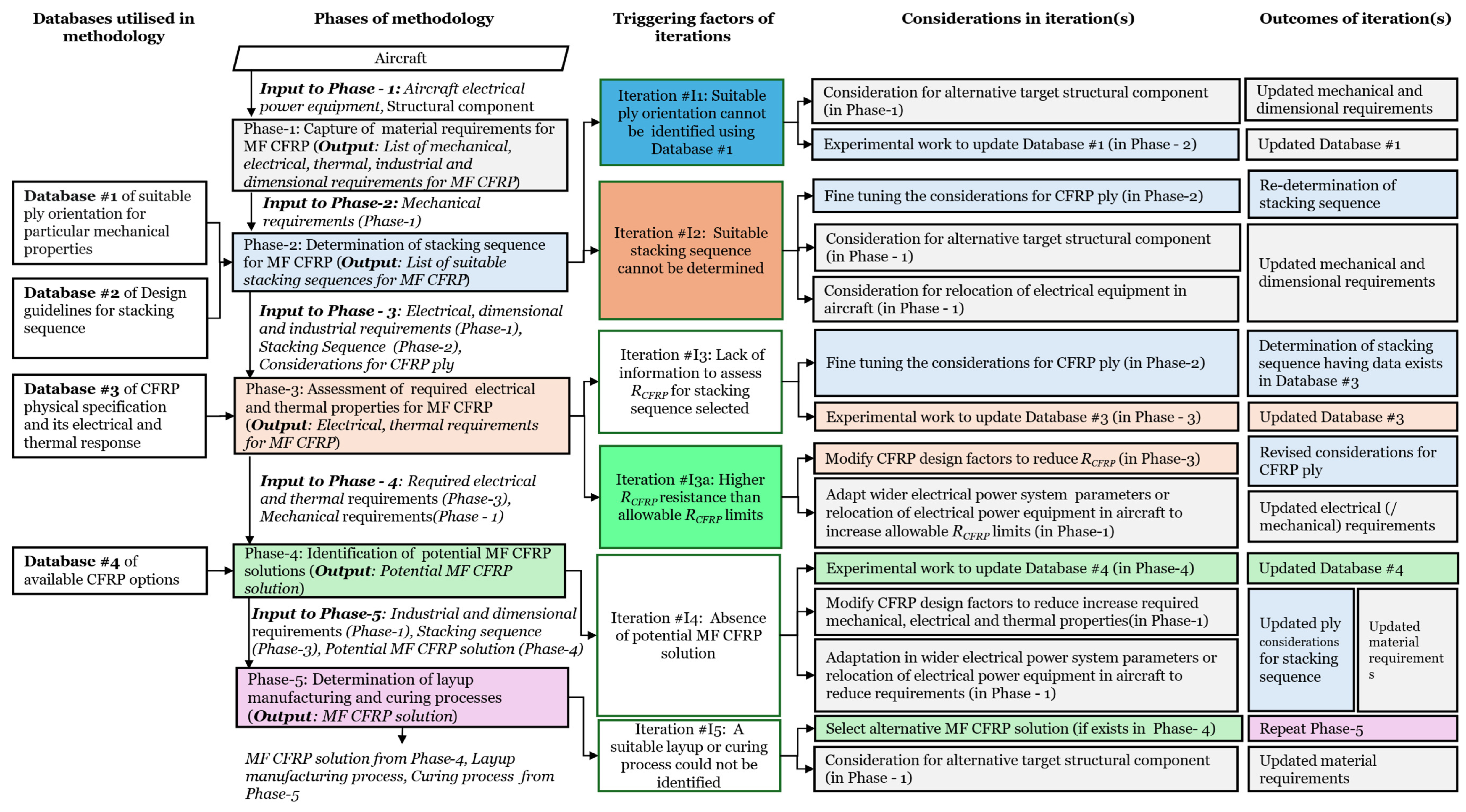
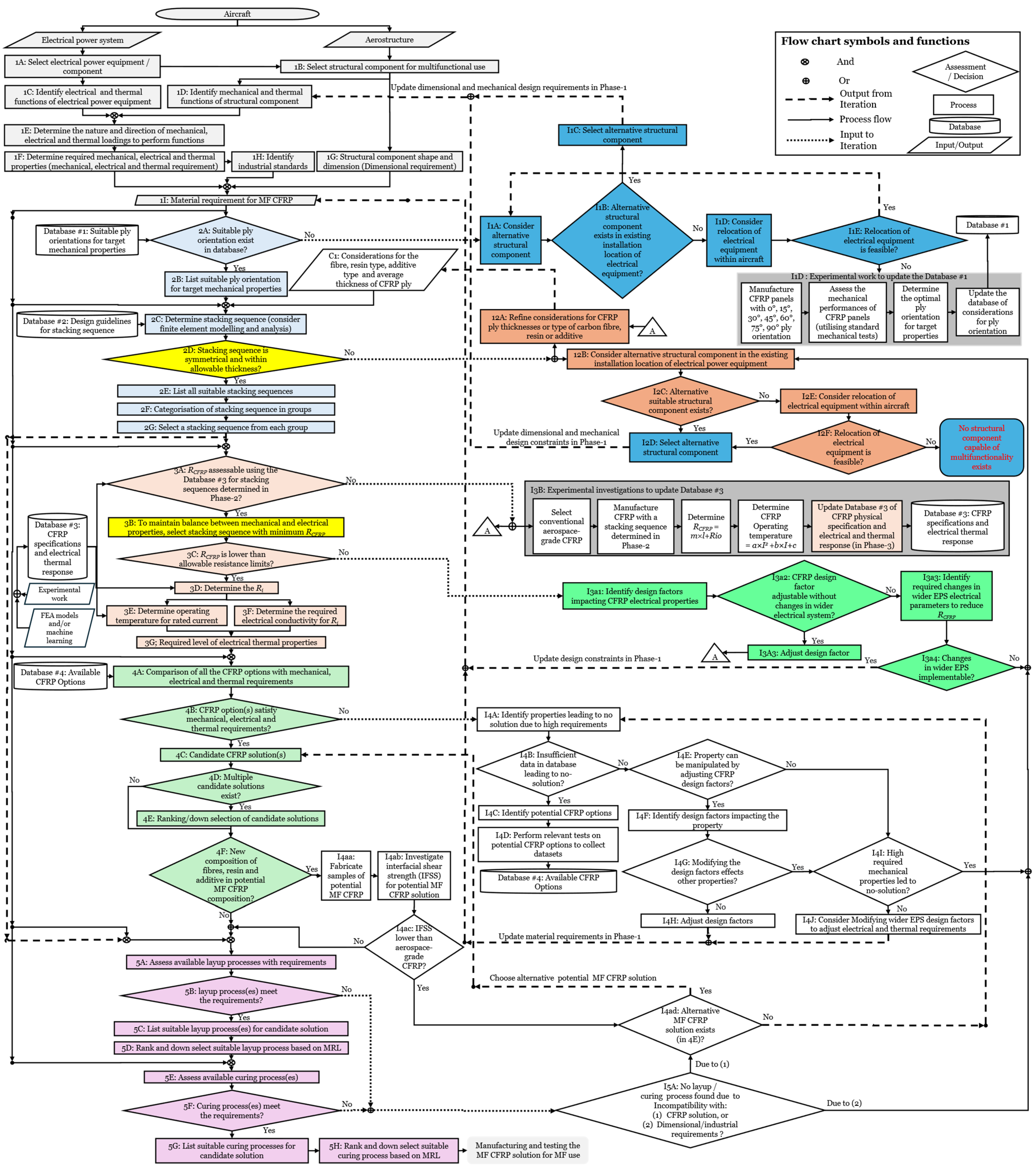
Figure 1 shows the high-level block diagram of the methodology consisting of five phases, with iterative loops for modifying CFRP properties or refining requirements when no solution is initially found for MF-CFRP. In
Figure 1 (and the rest of the figures in the manuscript), colours are added to differentiate between different phases of the methodology. Phase 1 (highlighted in off-white) captures the mechanical, electrical, thermal, and dimensional requirements for MF-CFRP based on aero-structural and EPS requirements. In Phase 2 (highlighted in light blue), suitable ply orientations are identified based on the required mechanical properties of structural components. These ply orientations are then used to determine suitable stacking sequences for MF-CFRP that are output to Phase 3. In Phase 3 (highlighted in orange), electrical resistance, conductivity, and
Tg for MF-CFRP with the stacking sequence are assessed to capture the required electrical and thermal properties of MF-CFRP and output to Phase 4. In Phase 4 (highlighted in green), MF-CFRP solutions that satisfy the requirements of mechanical, electrical, and thermal properties are selected. If multiple solutions are identified, they are ranked. The best solution is to output to Phase 5. In Phase 5 (highlighted in pink), manufacturing methods for the selected MF-CFRP solution are identified.
Throughout the methodology, databases are used to inform the decision-making with datasets of material properties, stacking sequence guidelines, and industry design thresholds. These are populated from industry standards, aviation-related certification specifications, and advisory circular documents, derived from the published academic literature and datasheets, and experimental activity. The methodology also provides iterative loops for adjusting earlier stages to reach an MF CFRP solution, for example, determining stacking sequence or initial consideration for CFRP ply, when new information becomes available, such as updated EPS requirements or material property data. These iterations align with engineering activities occurring during development timelines.
3.1. Phase-1: Capture of Material Requirements for MF-CFRP
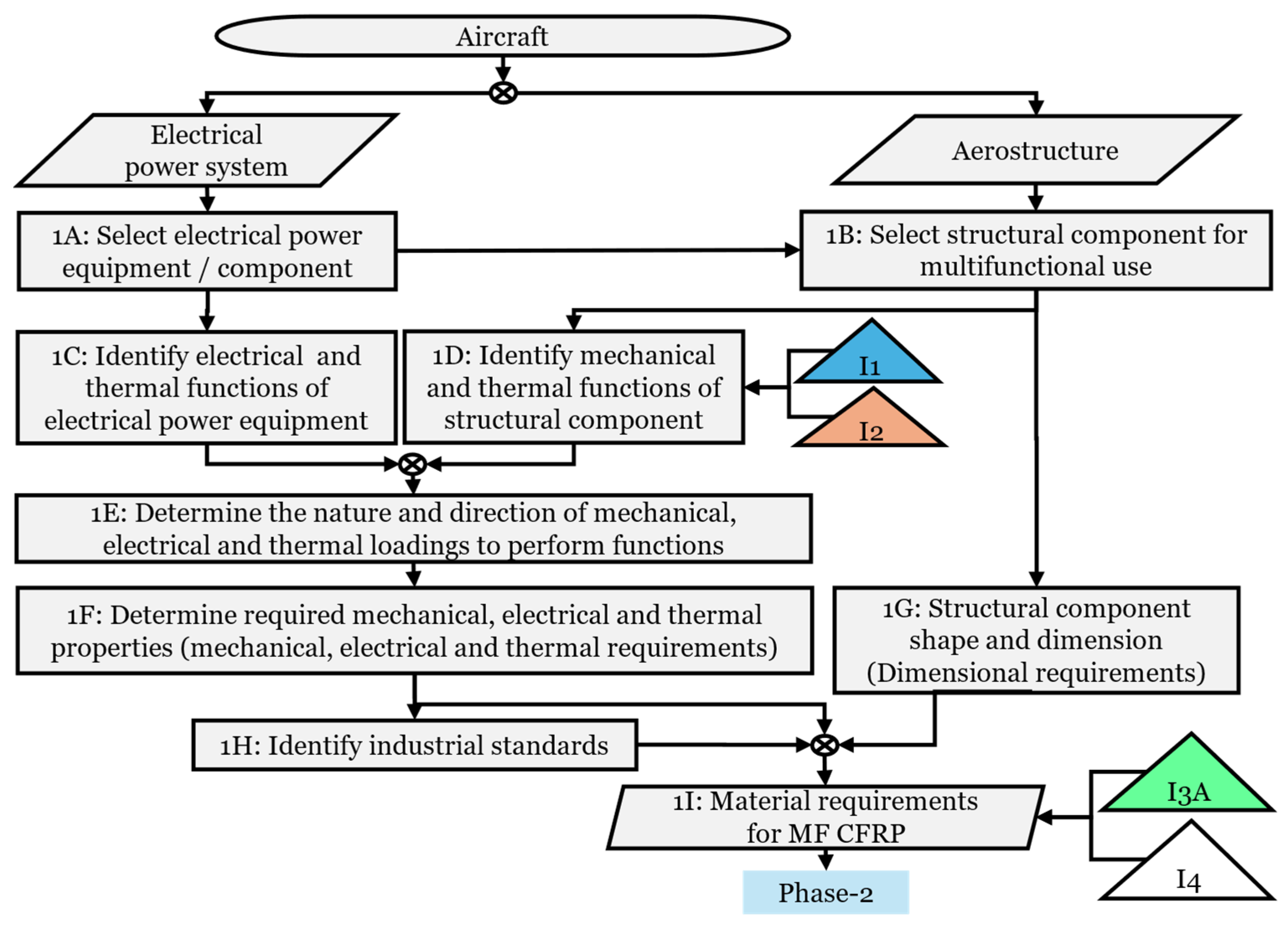
Phase 1 (
Figure 2) of the methodology captures the mechanical, electrical, and thermal material requirements for MF-CFRP based on structural and electrical power components within aircraft EPS. Step 1A involves the selection of electrical power equipment from the aircraft EPS. The electrical parameters of rated voltage, power, frequency, and operating duration for electrical current conduction are identified. Step 1B selects a corresponding structural component from the electrical equipment’s installation location.
Steps 1C and 1D determine the functions related to electrical and thermal requirements for the electrical equipment, with mechanical and thermal requirements for the structural component. Functions refer to the roles each component must fulfil. Step 1E identifies the nature of the loadings on the components: mechanical (e.g., tensile, compressive, bending, and shear), electrical (voltage, current, duration, and frequency), and thermal (environmental temperature and Joule heating) of the component.
In Step 1F, the required material properties for MF-CFRP are determined based on the nature of the loadings. Properties that define the baseline laminate performance necessary to meet multifunctional structural and electrical requirements are considered in this step. These properties could include tensile, compressive, flexural and shear strength, electrical conductivity, and thermal stability. The methodology considers baseline properties as they represent the intrinsic behaviour of the laminate before the introduction of geometric discontinuities like joints or holes. The methodology has the capability to include MF CFRP roles of electromagnetic interference (EMI) shielding and lightning strike protection, by including these as functional requirements within Step 1F. Environmental durability considerations (e.g., hygrothermal ageing, UV exposure, repairability) can also be captured at this stage by defining minimum acceptable long-term property thresholds based on operational environment and certification requirements. However, these functions will require a dataset of properties of surface conductivity, shielding effectiveness, and physical phenomena involved in lightning strikes that are not addressed in the current material database.
Step 1G identifies the structural component geometry (shape, length, width, and thickness) while considering installation limitations. Step 1H identifies relevant industrial standards for compliance with established mechanical, electrical, and thermal requirements. These standards list safety factors for structural reliability and acceptable void content in CFRP. While there are currently no standards that directly specify the use of CFRP as a primary conductor in aircraft electrical systems, existing standards of allowable voltage drop percentages [
40] and electrode configurations specific to CFRP bonding methods [
41] are used as reference points to establish threshold values for electrical and thermal properties. The minimum
Vf for optimal electrical conductivity, tensile strength, and flexural strength is also considered in Step 1H.
In the absence of dedicated standards for MF-CFRP, this methodology uses existing aerospace material and systems standards to define acceptable performance thresholds. For example, allowable voltage drop limits are used to calculate the maximum permissible electrical resistance across the CFRP component,
Rallowable (Ω), using Equation (1).
where
Vrated (
V) is the rated voltage of electrical power equipment,
Irated (
A) is the rated current of electrical power equipment, and
V% (%) is the allowable voltage drop across the component.
Besides voltage drop, another critical limit for MF-CFRP is power dissipation due to Joule heating, which must not cause a local temperature rise to exceed the CFRP maximum allowable service temperature. Thus, the performance limits of voltage drop and thermal safety limit the acceptable resistance of the CFRP-based component. This dual limitation is important to determine if a given CFRP can satisfy electrical and thermal requirements. At the end of Phase 1, Step 1I establishes a list of dimensional, mechanical, electrical, and thermal requirements organised into categories as detailed in
Table 2. This structured output ensures that all important aspects influencing MF-CFRP design are addressed to support later phases.
Phase-1 has iterative transfer-in blocks (#I1, #I2, #I3A, #I4) representing adaptive refinements used later in Phase-2 to Phase-4. These iterative adjustments can adapt the design, change structural component selection, or update EPS configuration. Details of these iterations are included in
Section 3.2,
Section 3.3 and
Section 3.4.
3.2. Phase-2: Determination of Suitable Stacking Sequences for MF-CFRP
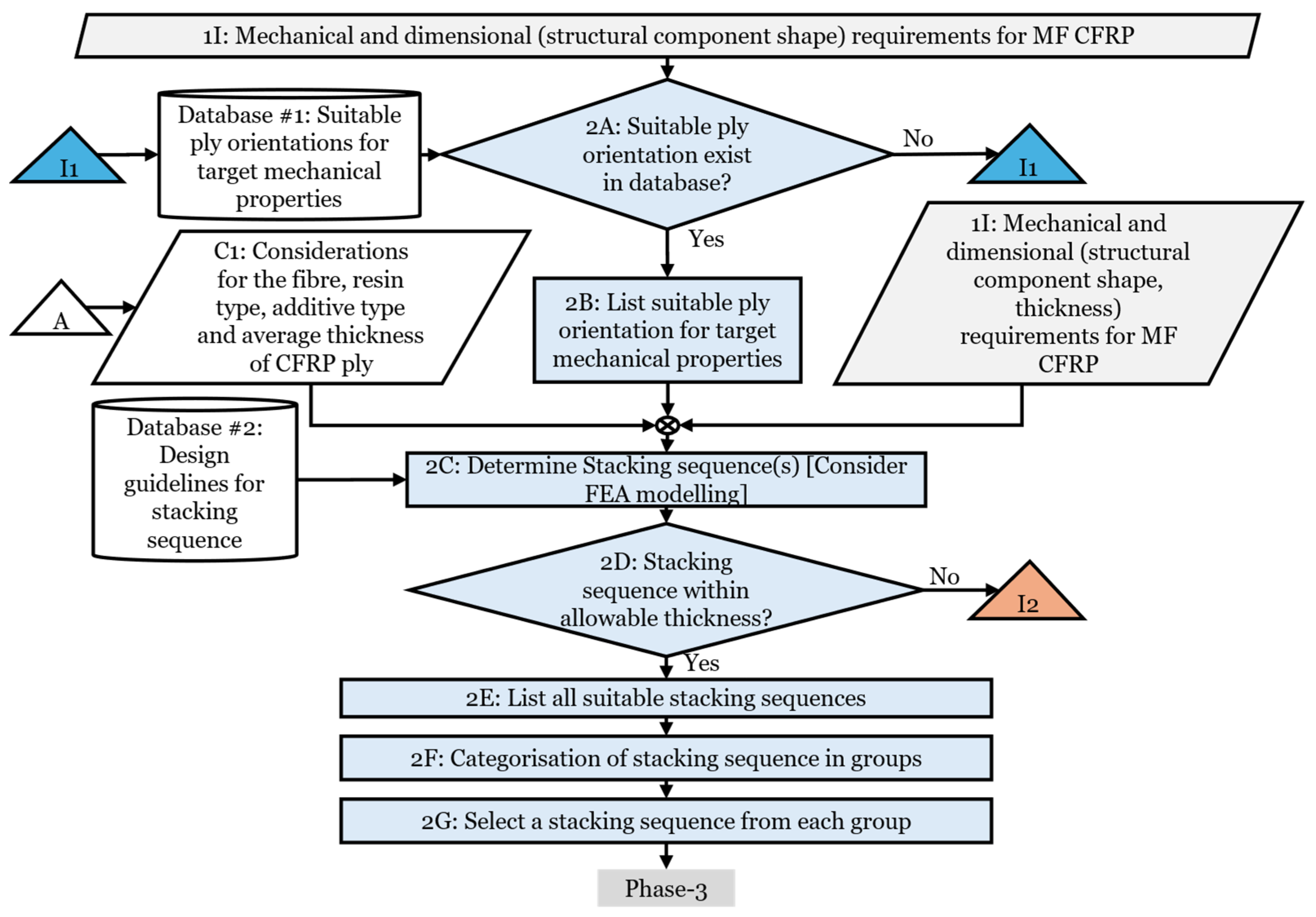
Phase 2 of the methodology focuses on suitable stacking sequences for MF-CFRP that influence the electrical and thermal properties, illustrated in
Figure 3. Step 2A takes the mechanical properties and structural shape requirements from Phase 1 to determine the ply orientations. Step 2A follows the method in [
42] to determine the stacking sequence, where fibre orientation is treated as the primary design variable and used to create layups with the required mechanical properties. Step 2A refers to Database #1, “Suitable ply orientations for mechanical properties of CFRP”, which provides orientations relative to CFRP shapes and mechanical properties (presented in
Table 3). Database #1 focuses on non-woven fabric rather than woven fabrics because non-woven fabric provides continuous, aligned fibre pathways that maximise the longitudinal mechanical strength of CFRP ply. Woven CFRP introduces fibre crimp, which reduces stiffness [
43]. Once the suitable ply orientations are identified, a list of suitable ply orientations for target mechanical properties is listed in Step 2B.
In Step 2C, suitable stacking sequences are identified by combining Phase 1 mechanical and dimensional requirements with determined ply orientations. Analytical methods (e.g., Classical Lamination Theory [
48]) can be used to predict laminate behaviour, and techniques such as Finite Element Analysis (FEA) [
49,
50,
51] can be utilised to determine suitable stacking sequences. Database #2, titled “Design guidelines for CFRP stacking sequence” (
Table 4), guides the stacking sequence determination and is extracted from MIL-HDBK-17 [
52]. These guidelines, also referred to as “design rules”, comprise homogeneous stacking, a 10% rule for ply orientation diversity, symmetrical and balanced arrangements, and damage tolerance strategies, and are aimed at the mechanical strength of CFRP. The type of fibre and resin has not been selected at this point, and the ply thickness is unknown. Therefore, initial assumptions based on aerospace-grade CFRP (0.125 mm ply thickness, PAN-based carbon fibre, epoxy resin) are adopted following the approach in [
53]. CFRP laminate thickness is matched to the structural component selected in Phase 1 for compatibility with the installation location. The maximum allowable ply number (
n) is calculated using Equation (2):
where
T (mm) is the maximum allowable thickness of the CFRP laminate and
t (mm) is the CFRP ply thickness.
If multiple stacking sequences satisfy mechanical requirements, they are grouped based on ply orientation consistency (Step 2F). The grouping is justified by evidence that altering ply positions around a laminate mid-plane has a minimum impact on the mechanical strength of CFRP [
54]. Consecutive plies of identical orientation are prioritised from these groups to minimise errors and complexity during the CFRP laminate fabrication. Selected stacking sequences are output to Phase 3 for assessments of the electrical and thermal requirements of MF-CFRP.
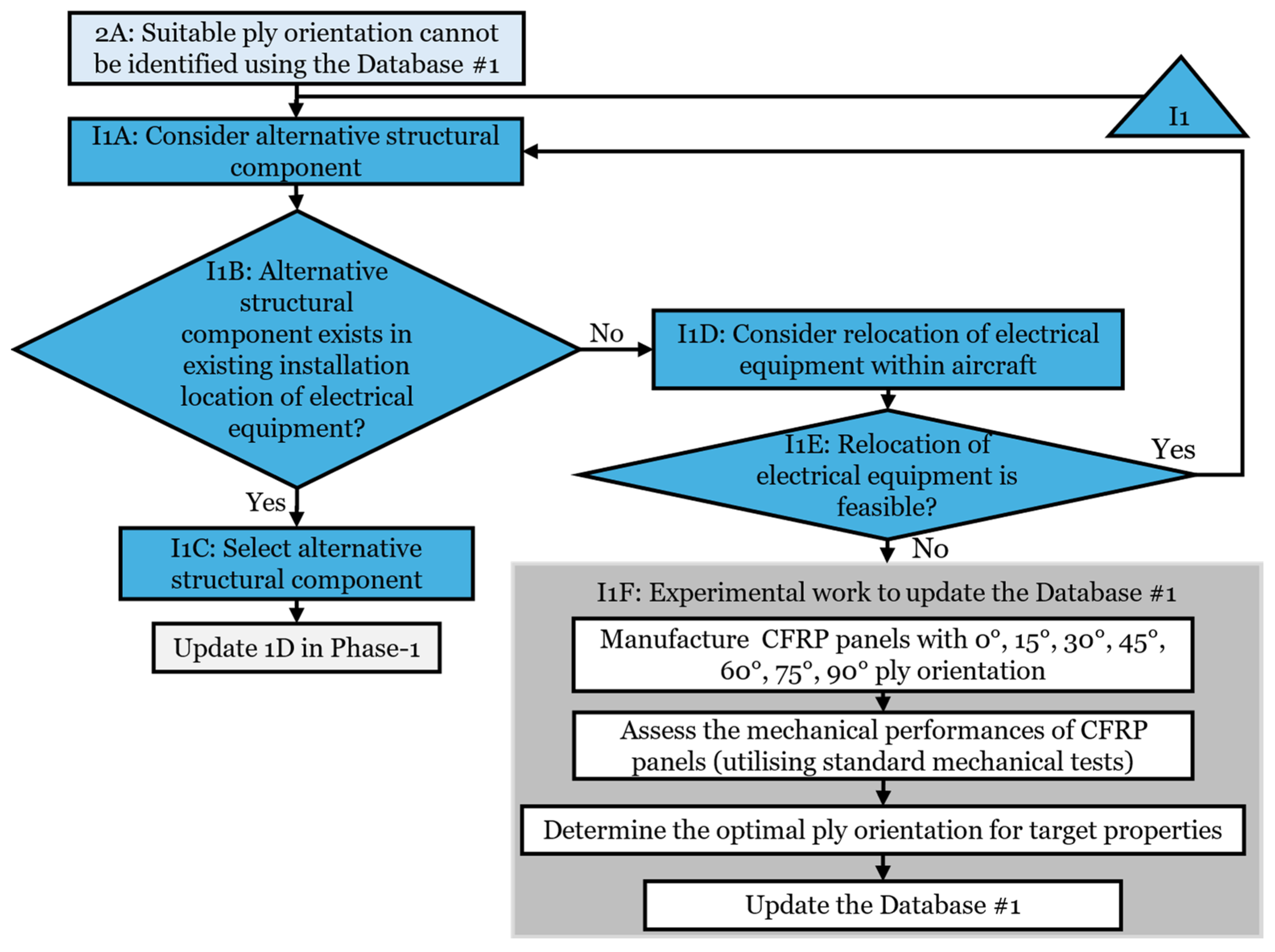
Phase 2 includes iterations (I1, I2) that are used when ply orientations or suitable sequences cannot be determined. Iteration #I1 (illustrated in
Figure 4) is used if Database #1 lacks suitable ply orientations for the shape of the selected structural component.
In Iteration #I1, alternative structural components or experimentally determining the ply orientations are evaluated. If feasible, alternative structural components are chosen, and requirements in Phase 1 are updated accordingly. Otherwise, the experimental validation using appropriate ASTM standards (for example, D3039 [
55]) identifies optimal ply orientations for the selected structural shape, and Database #1 is updated.
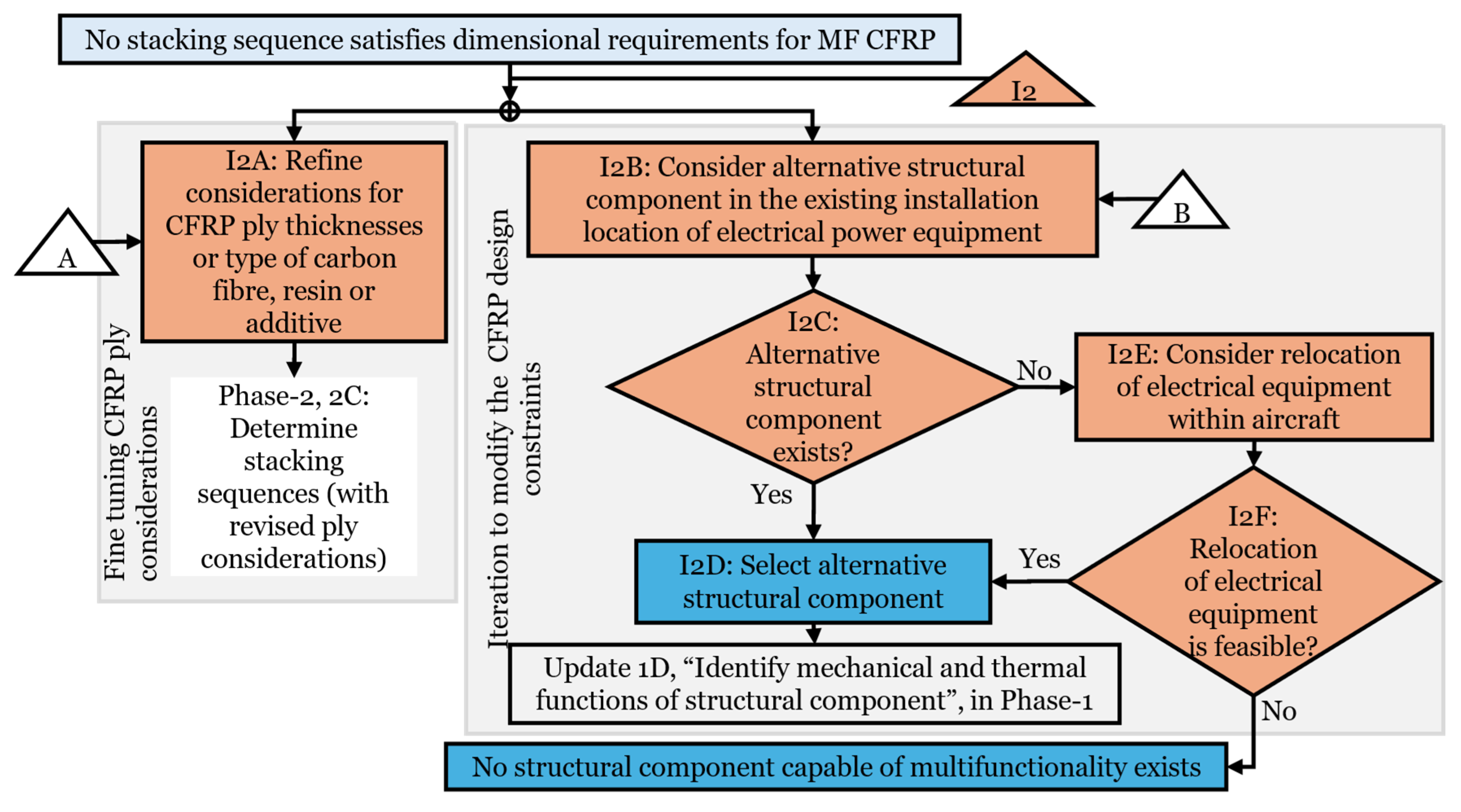
Iteration #I2 (
Figure 5) is used if no suitable stacking sequence meets the laminate thickness requirement. This iteration refines design factors related to CFRP ply consideration based on studies showing the sensitivity of mechanical properties to these design factors [
56,
57,
58,
59]. Example adjustments include a selection of alternative carbon fibres or resin, and recalculation of the allowable number of plies for the revised laminate changes. Updated ply considerations are re-evaluated in Step 2C. If the refinements remain inadequate, Iteration #I2 considers alternative structural components within the existing aircraft location that are candidates for multi-functionality. If alternative structural components are available, requirements in Phase 1 are updated. Otherwise, relocation of electrical equipment is considered, if possible, without compromising equipment or wider electrical system functionality. If neither alternative structural components nor relocation is feasible, the methodology concludes that the current mechanical and dimensional requirements prevent a suitable stacking sequence from being achieved. The iteration process ensures that the methodology explores possible options to adjust the viable solution space before concluding that a solution is not feasible.
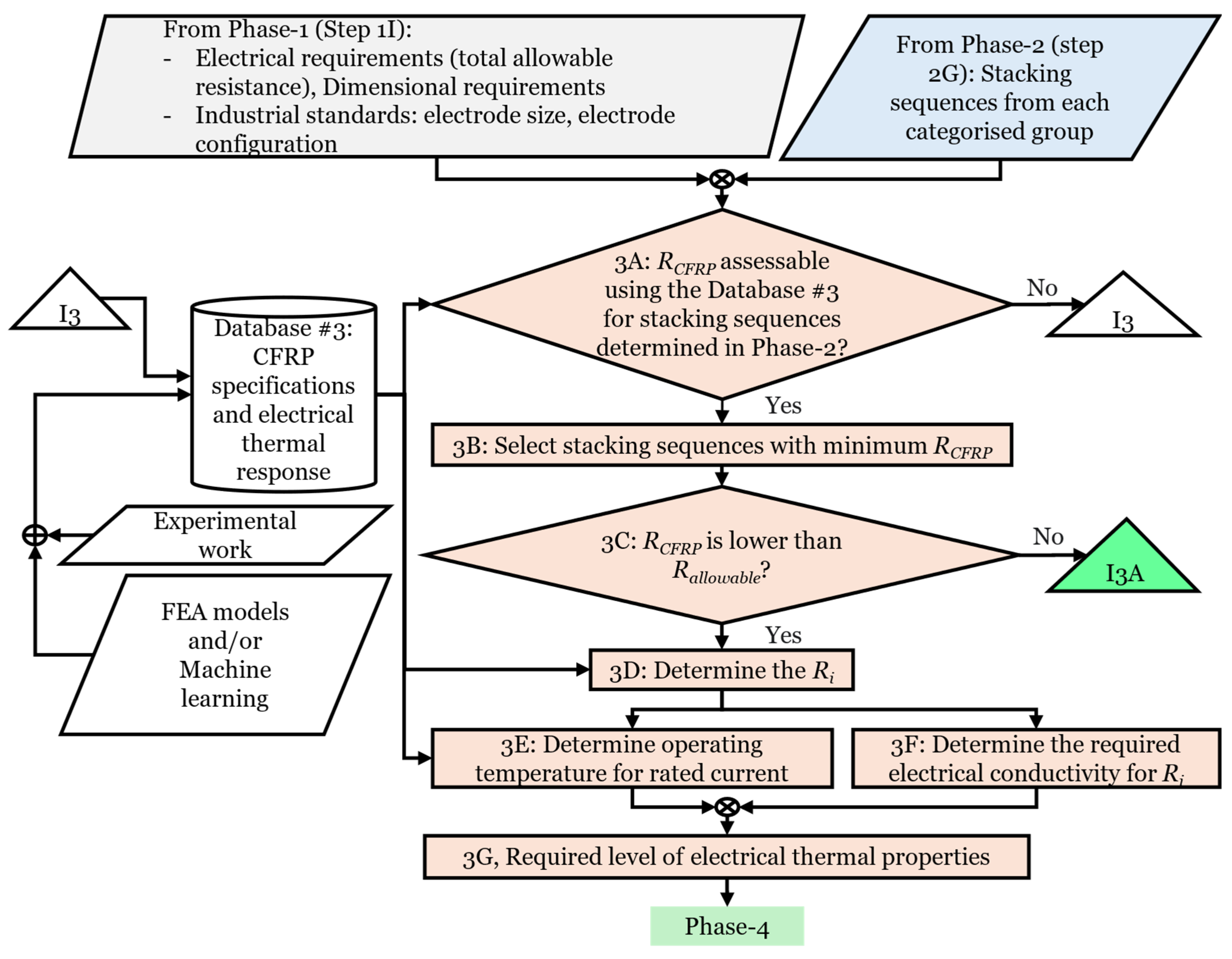
3.3. Phase 3: Assessment of Required Electrical and Thermal Properties for MF-CFRP
Phase 3 of the methodology assesses the required electrical and thermal properties for MF-CFRP, as illustrated in
Figure 6. The assessment takes inputs of electrical ratings (current, voltage, and power), dimensional requirements (length, width, and thickness), industrial standards (allowable resistance and electrode configuration), and selected stacking sequences from Phases 1 and 2.
Phase 3 uses Database #3, “CFRP specifications and electrical and thermal response”, structured to relate CFRP physical characteristics of fibre type, matrix material, additives, stacking sequences, electrode configuration, and size with electrical (total electrical resistance (
RCFRP)) and current-induced thermal (operating temperature) responses (
Table 5). Database #3 is experimentally driven, with the electro-thermal response of CFRP captured in lab tests. In addition to experimental datasets, there is an opportunity to use modelling tools, such as FEA, to estimate the electro-thermal response of CFRP when experimental data are unavailable. FEA models can simulate current distribution, Joule heating, and temperature rise in CFRP [
60,
61]. There is also an opportunity to investigate the use of machine-learning methods trained on existing mechanical, electrical, and thermal datasets to approximate CFRP properties for new material systems. Such modelling approaches could supplement experimental measurements and allow early-stage evaluation of laminate configurations, without requiring comprehensive experimental work. Database #3 is critical in defining the scope and limitations of the methodology. Step 3A calculates the
RCFRP of the selected stacking sequences using Equation (3):
where
m is the slope representing the resistance per unit length of the CFRP,
l (m) is the length of the CFRP sample, and
Rio (Ω) represents the sum of resistances (
Ri and
Ro) at the electrical current entry and exit points of the CFRP. The literature justifies the consideration of
Ri and
Ro separately, since the highest temperatures typically occur at electrode contact points due to higher current density concentrations, in turn due to the smaller cross-sectional conducting area [
62].
Following the resistance calculation (Step 3A), stacking sequences with minimum RCFRP are identified (Step 3B) and compared against Rallowable, calculated in Phase 1. If RCFRP is within allowable limits (Step 3C), then electrode-interface resistance, Ri, which is half of Rio (Ω), is determined (Step 3D).
In Step 3E, the final steady state operating temperature
Ts (°C) of CFRP is estimated using Equation (4) obtained from experimental work relating the temperature rise in CFRP due to Joule heating for specific layup orientations and stacking sequences.
where
Ts (°C) is the final steady state temperature against applied current,
I (A),
a and
b are quadratic and linear coefficients relating temperature rise in response to current injection, and
c (°C) represents ambient temperature. The calculated
Ts is used to determine the required resin
Tg, following MIL-HDBK-17-1F, which recommends a
Tg at least 28 °C higher than the operating temperature for reliability [
63].
Table 5.
Database #3: CFRP physical specification and electro-thermal response.
Table 5.
Database #3: CFRP physical specification and electro-thermal response.
| Fibre | Matrix | Additive | Additive Incorporation Technique | Stacking Sequence | Electrode Configuration | Electrode Size (mm) | RCFRP and Rio (Ω) | CFRP Operating Temperature and Current (I), (°C) | Source |
|---|
| PAN | Epoxy | None | N/A | [0/90]16 | End-to-end (longitudinal direction) | 5 × 4 | 0.73 × L + 0.023 | 0.55 × I2 + 5.07 × I + 10.04 | Experimental work by authors |
| [0/90]16 | End-to-end (longitudinal direction) | 10 × 4 | 0.53 × L + 0.021 | 0.48 × I2 + 0.75 × I + 18.27 |
| [0/90]16 | End-to-end (longitudinal direction) | 50 × 4 | 0.24 × L + 0.0118 | Not reported |
| [0/90]s | Surface-to-surface | - | 0.0047 × L + 0.88 | Not reported | [64] |
| [0]32 | surface-to-surface | 10 × 10 | 0.8564 × L + 0.379 | [11] |
Where required and corresponding datasets or models are available, additional performance assessments of frequency-dependent surface conductivity for EMI shielding or thermal–electrical coupling relevant to lightning strike protection can also be considered in Step 3E. Environmental durability factors of moisture-conditioned conductivity, temperature-dependent resistance evolution, and long-term thermal cycling effects may also be evaluated in Step 3E.
Step 3F, the required electrical conductivity
σ (S/m) for the longitudinal direction of MF-CFRP is calculated using Equation (5).
where
A (m
2) is the area of current injection. This calculation assumes that electrodes are placed at the ends of the CFRP, as illustrated in
Figure 7. Once the electrical and thermal requirements for MF-CFRP are assessed in Step 3G of Phase 3, it is output to Phase 4. The methodology focuses on DC and low-frequency AC, where CFRP behaves as a purely resistive material [
65], representative of existing aircraft EPS operating voltages, for example, ±270 V
DC and 115 V
AC (360—800 Hz). Therefore, frequency-dependent impedance effects at higher frequencies are not considered.
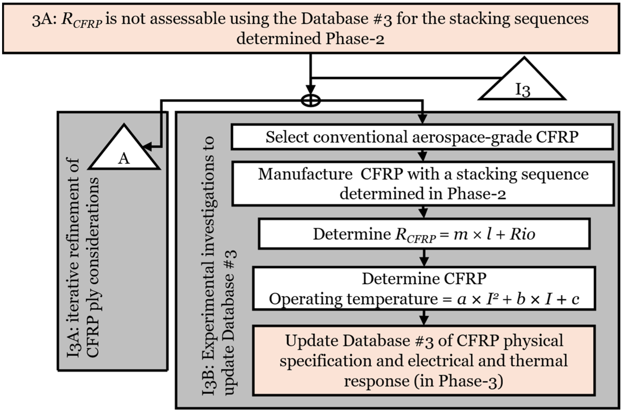
If in Step 3A, the
RCFRP of CFRP with the selected stacking sequence cannot be estimated using the datasets in Database #3, Iteration #I3 is triggered. In Iteration #I3 (
Figure 8), refinement of CFRP ply considerations in Phase 2 (Transfer-Out Block #I3) is made to determine a stacking sequence whose electrical and thermal properties can be determined using Database #3. Iteration #I3 transfers adjustments in CFRP ply considerations back into Phase 2.
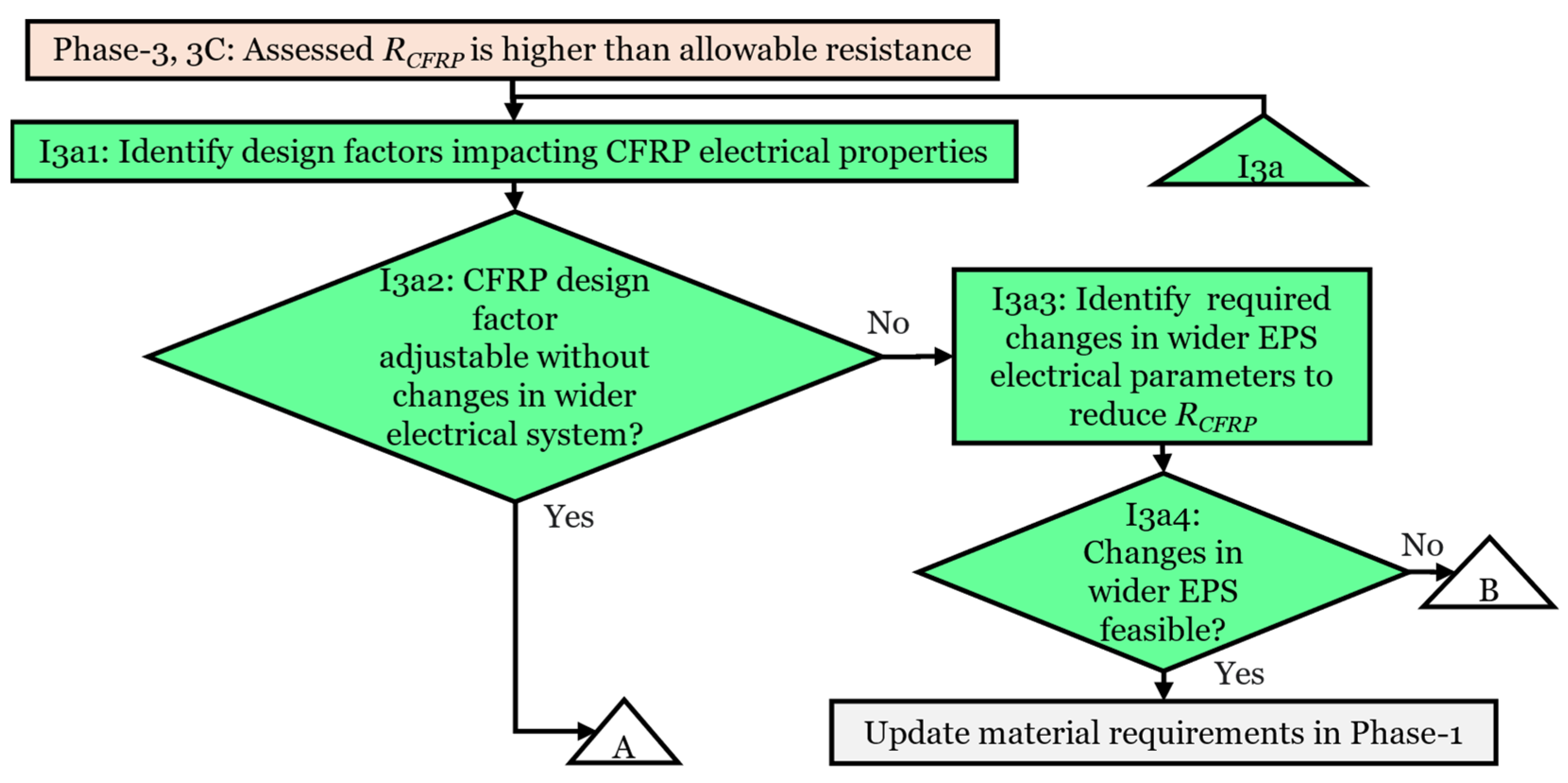
If Step 3A provides an
RCFRP exceeding
Rallowable, Iteration #I3a (Transfer-Out Block I3a of Phase 3) is activated. Iteration #I3a (
Figure 9) facilitates decision-making to reduce
RCFRP or adjust
Rallowable. Step I3a1 identifies design modifications grouped into two categories (
Table 6) of CFRP-based refinements (fibre type, resin, additives, and electrode size/configuration) directly affecting electrical properties without altering broader EPS design, or EPS-based adjustments (load power rating, voltage rating, and allowable voltage drop) requiring changes to the wider EPS system. The design factors in
Table 6 are sequenced to facilitate the design adjustments based on their feasibility and overall impact on the larger EPS to minimise disruption.
CFRP adjustments (design factors #1–5,
Table 6) are prioritised due to their minimum disruption to wider EPS system parameters and are transferred to Iteration #I2, Step I2A (
Figure 5), refining ply configurations to reduce
RCFRP. If EPS adjustments (design factors #6–10,
Table 6) are necessary, the feasibility of their applicability is assessed in Iteration #I3a. If feasible, initial requirements in Phase 1 are updated, and stacking sequences are determined accordingly. Iteration #I3a ensures a thorough exploration of all potential options to reach a solution. If no appropriate solution is identified, the methodology concludes that existing mechanical and dimensional requirements prevent a suitable MF-CFRP stacking sequence from being selected.
The iterative processes (#I3, #I3a) show iterative refinement strategies consistent with the Material Selection Activities concept proposed in [
38], where incremental refinement is presented as an approach to achieving a viable solution when addressing material selection and design challenges, which will seldom all be solved in one step.
3.4. Phase 4: Identification of Potential MF-CFRP Solutions
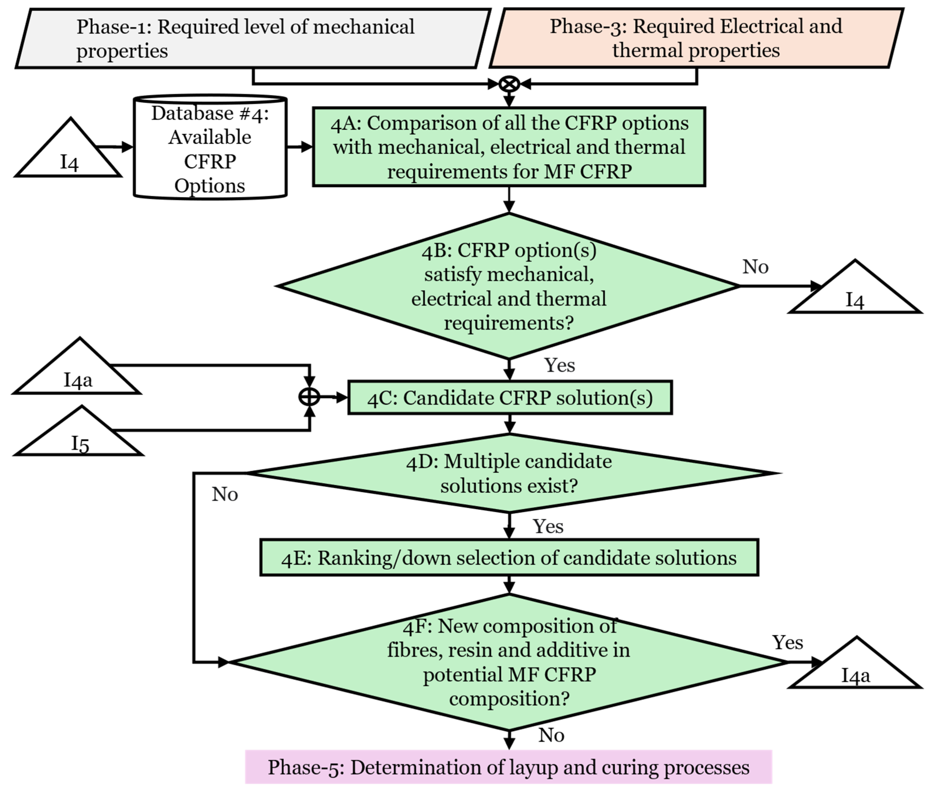
Phase 4 (
Figure 10) identifies potential MF-CFRP solutions meeting mechanical, electrical, and thermal requirements determined in Phases 1 and 3. In Step 4A, required properties from earlier phases are compared against available CFRP options listed in Database #4 (
Table 7). Database #4 contains commercial and literature-based CFRP options, detailing properties of prepregs and composite materials with combinations of PAN-based and Pitch-based carbon fibres, resins, and additives. Potential options with incomplete property data are considered viable if evidence from the literature supports the possibility of them satisfying requirements. Step 4B assesses the available CFRP options with requirements. If CFRP option (s) meet the multifunctional requirements, they are compiled as potential MF-CFRP solutions in Step 4C. Step 4D determines if single or multiple potential CFRP solutions exist. If there is only one potential solution, it moves directly to Step 4F; otherwise, in Step 4E, potential solutions are scored and ranked to determine the best solution to output to Phase 5. In cases of tied scores between potential MF-CFRP solutions, Technology Readiness Level and cost are used as deciding factors for a tie-break.
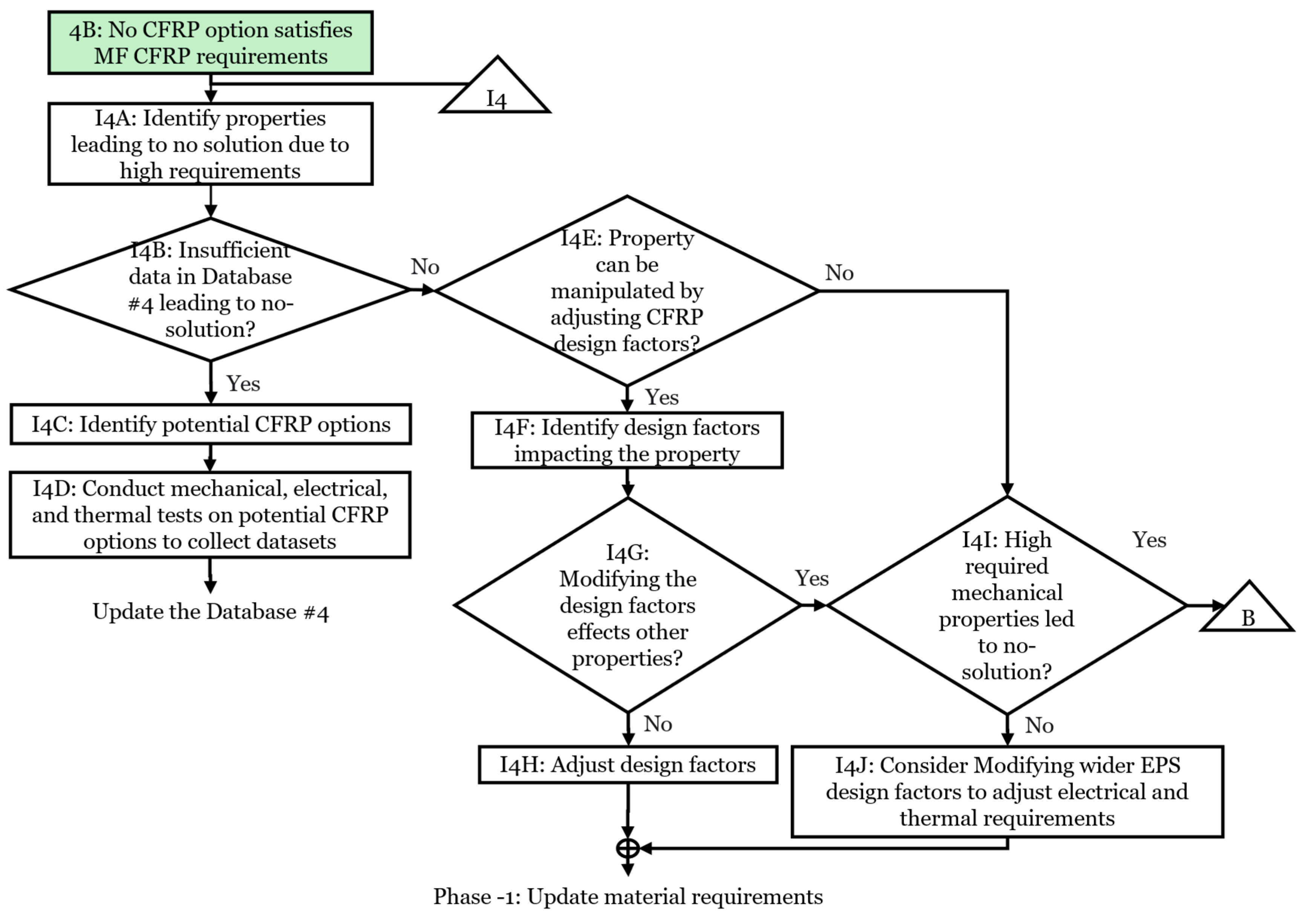
If no CFRP solution meets the requirements (Step 4C), Iteration #I4 (
Figure 11) is used. Iteration #I4 assesses whether incomplete data in Database #4 or excessive requirements limit the identification of potential MF-CFRP solutions. If needed, experimental work is undertaken to update Database #4. Adjustments to CFRP design factors (fibre type, resin, additives, and electrode configuration) or EPS parameters (voltage, current, and allowable voltage drop) may be considered. If such modifications are suitable, requirements in Phase 1 are revised accordingly. Iteration #I4 priorities lower-impact adjustments and begins with EPS parameters for minimum structural disruption. If EPS modifications are not enough, alternative structural components or relocation of electrical equipment are considered as more complex alternatives.
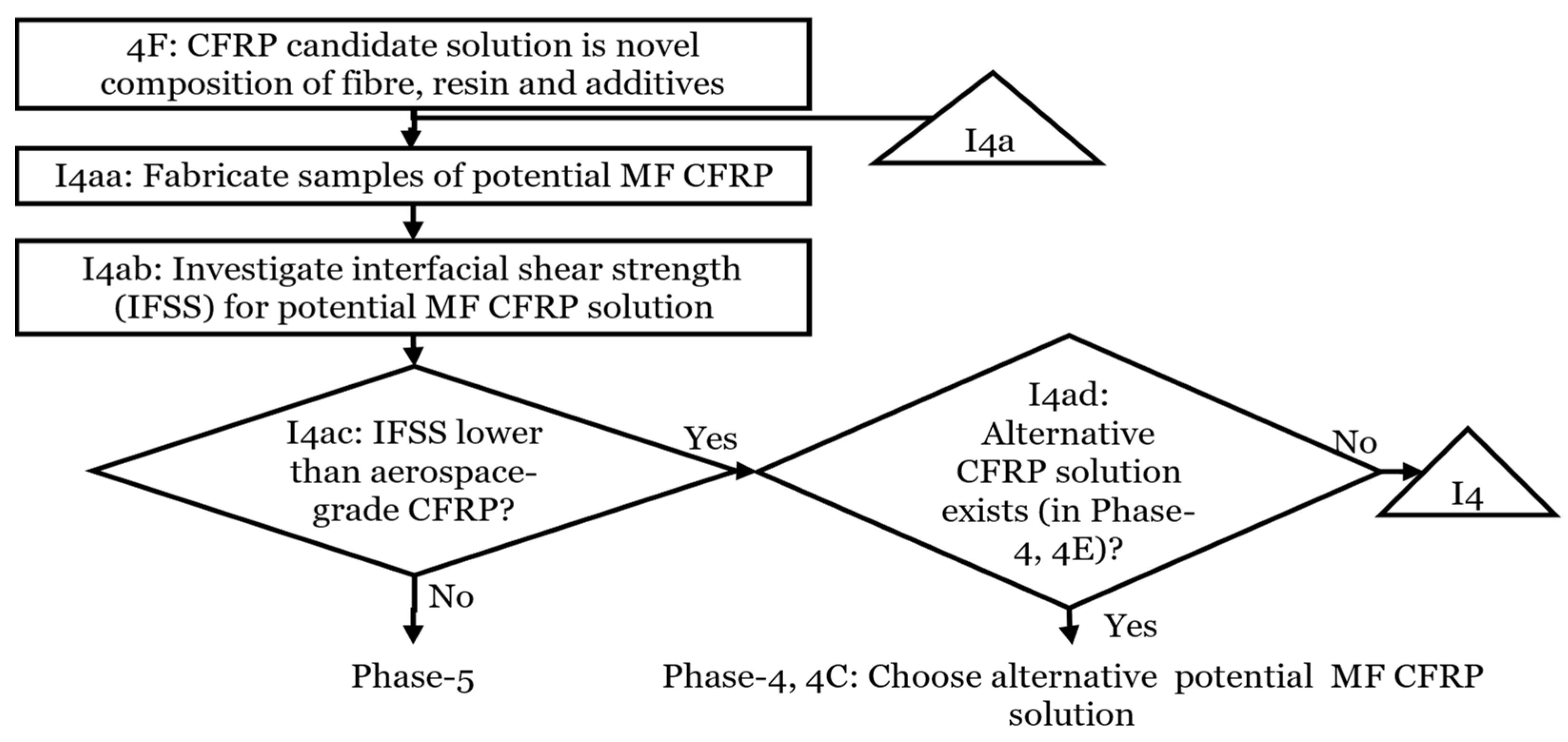
If the fibre–resin-additive composition is new, Iteration #I4a is initiated. Iteration #I4a (
Figure 12) involves experimental evaluation of Inter-Facial Shear Strength (IFSS). In IFSS, the shear strength at the interface of the fibre and resin due to chemical bonding is determined [
66]. IFSS affects load transferability from resin to carbon fibres and is important for compression strength, flexural strength, and ILSS of CFRP [
67].
Iteration #I4a specifically addresses novel fibre–resin-additive compositions (
Figure 12). Fabrication and testing of CFRP samples assess IFSS properties, comparing them to established aerospace-grade CFRPs. Solutions demonstrating comparable or better IFSS are output to Phase 5. If IFSS is insufficient, alternative CFRP solutions are explored. If no viable alternatives are available, Iteration #I4 is revisited to identify further potential MF-CFRP solutions.
3.5. Phase-5: Determination of Layup and Curing Processes for Potential MF-CFRP Solutions
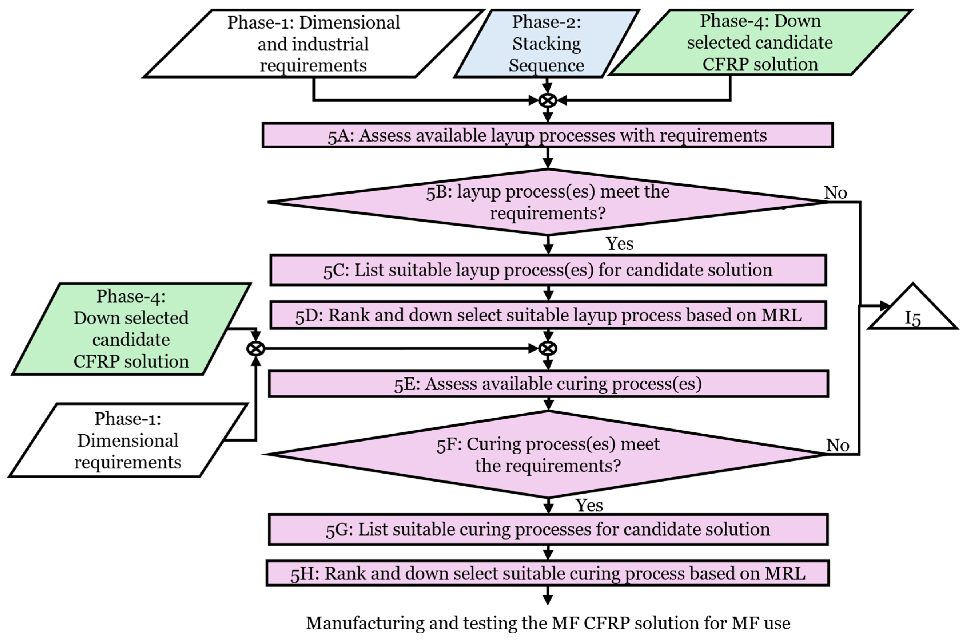
Phase 5 identifies suitable layup and curing processes for the potential MF-CFRP solution selected in Phase 4 (
Figure 13). Phase 5 assesses whether the CFRP solution identified in Phase 4 can be realised using available manufacturing processes. This is the point at which manufacturability is assessed explicitly, acknowledging that some stacking sequences, laminate thicknesses, or property combinations selected earlier may not be achievable in practice. When such limitations arise, the methodology iterates to earlier phases so that material properties, dimensions, or EPS requirements can be refined. Thus, Phase 5 supports manufacturing-informed iteration rather than simply accepting or rejecting a proposed MF CFRP solution or configuration.
Step 5A of Phase 5 considers manufacturing processes based on factors derived from industrial standards and MF CFRP requirements. These factors are component shape, compatibility with laminate size, industrial standards for void content, and minimum Vf from Phase-1, stacking sequence from Phase-2, and CFRP composition of prepreg or dry fibres, resin type, and additives from Phase-4. The likelihood of process-induced defects, such as wrinkling, porosity, or resin-rich areas, can also be considered in Step 5A. These factors are important because they directly affect the mechanical, electrical, and thermal properties of the MF-CFRP.
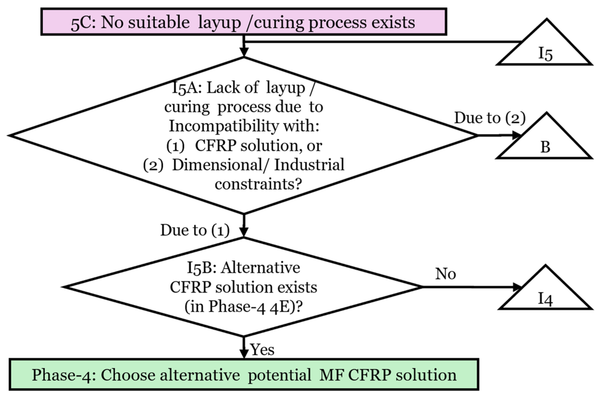
If no manufacturing process meets the requirements at the decision point of Step 5B, Iteration #I5 is initiated. Here, “Meeting the requirements” refers to a check against key manufacturability criteria of achievable
Vf, expected void content, compatibility with the target laminate thickness, dimensional tolerances, and the risk of defects such as wrinkling, porosity, or resin-rich regions. If, in Step 5B, one or more layup or curing methods satisfy the requirements, Step 5C lists the suitable layup methods. When several options are available, Step 5D ranks them using Manufacturing Readiness Level (MRL) to reflect their maturity for aerospace production [
68].
Step 5E assesses a suitable curing process using criteria of temperature–pressure capability and cycle duration (typically provided by CFRP manufacturers), and their ability to achieve the required
Tg and dimensional stability. If no curing method matches the requirements (Step 5F), Iteration #I5 (shown in
Figure 14) is used. Otherwise, suitable curing processes are listed (Step 5G). If multiple curing methods qualify, Step 5H ranks and selects the best option based on the MRL.
Iteration #I5 (
Figure 14) addresses situations where neither layup nor curing methods meet the manufacturing requirements of the selected MF-CFRP. Initially, Step I5A considers the reason for the lack of a suitable method, which could be either due to CFRP composition incompatibility or high dimensional/quality requirements. If composition issues arise, Step I5B refers to Phase 4 to select alternative MF-CFRP solutions from ranked candidates. Phase 5 is then revisited with this updated selection. If no alternative MF-CFRP solution exists, Iteration #4 of Phase 4 is triggered for a wider assessment of adjustments in CFRP design parameters or system-level changes to expand potential MF-CFRP solutions. Iteration #I5 also addresses manufacturability–performance trade-offs. For example, a situation may arise where a manufacturing process suits the required laminate geometry but imposes compromises, such as a reduced fibre volume fraction or increased void content. In such cases, the methodology assesses whether the compromise is within the acceptable limits defined in Phase 1. If not, earlier phases may be iterated to refine material, geometric, or stacking-sequence assumptions. This strategy ensures that all viable manufacturing processes are considered and manufacturability remains linked to design decisions.
If dimensional requirements, acceptable void content, or Vf limit process selection, Step I2B of Iteration #I1 (Phase-2) considers selecting alternative structural components or relocating electrical equipment. Feedback from Phase 5 guides this decision-making for the selection of an alternative structural component that aligns better with achievable manufacturing and curing processes to improve the feasibility of reaching an MF-CFRP solution.
4. Validation of the Methodology
The completeness and correctness of the methodology were validated by implementing a structured peer review with two experts from the National Manufacturing Institute Scotland, who specialise in CFRP design and manufacturing [
69]. Expert 1 has 15 years of experience in composite materials research and industrial applications. Expert 2 has eight years of applied experience in CFRP laminate processing and structural applications.
The validation process had two stages:
A detailed presentation was delivered in individual sessions to both experts, outlining the aim, scope, phases, iterative processes, and supporting databases of the methodology. Each session included a discussion to clarify specific assumptions and decision points.
A structured questionnaire was provided to each expert, with sections aligned with the phases and iterations of the methodology. Each statement was assessed using a five-point Likert scale and supplemented by feedback.
The expert assessment validated the overall structure and logic of the methodology. The experts confirmed that the methodology flow aligns with the requirements of MF-CFRP design and validated the iteration-driven approach presented in the methodology to reach a solution.
The methodology was refined based on expert review to improve its applicability and alignment with industry practices. The updates made to the methodology from the experts’ feedback are highlighted in
Figure 15, which presents a combined illustration of the methodology, integrating the phases detailed in
Section 3.1,
Section 3.2,
Section 3.3,
Section 3.4 and
Section 3.5. In Step 2D of Phase 2, symmetry was introduced as a design guideline to avoid potential warping and out-of-plane deformations during the curing and cooling of CFRP laminates to reduce manufacturing defects. In Phase 3, Step 3B was reworded to underpin the importance of maintaining a balance between mechanical and electrical properties during stacking sequence selection. This is achieved by selecting a stacking sequence with minimum
RCFRP, preventing prioritisation of either electrical or mechanical properties.
Expert 2 recommended the integration of data-driven modelling approaches to reduce the need for experimental testing. This suggestion was not implemented in the current iteration due to the limited availability of datasets. It is identified as a valuable direction for future development to improve the applicability of the methodology in early-stage designs.
The suggestion was made to re-order the phase with manufacturing, which was considered earlier in the methodology. However, maintaining the existing order of first design and selection of materials, followed by the determination of manufacturing method, was considered more appropriate for determining MF-CFRP design, where a wider range of material options needs to be assessed before narrowing down to manufacturing feasibility. The experts also suggested the inclusion of cost and manufacturing rate in future iterations of the methodology. At present, these are not included, as the focus is on meeting multifunctional requirements.
5. Demonstration of the Methodology Application for an MF-CFRP Cable Replacement Concept
This section used a case study with the aim of demonstrating the application of the methodology to design and select an MF-CFRP for aerostructure functioning both as a structural element and a current-carrying conductor. The case study did not aim to produce a fully optimised component, but rather to illustrate how the methodology supports systematic decision-making, iterative refinement, and data-driven assessment when integrating electrical functionality into a structural CFRP component.
In the case study, a 28 VDC power cable supplying 30 W to the avionics system was replaced with a CFRP-based floor-beam within the aircraft fuselage. Even though the case study considers a 28 VDC supply, the methodology is not limited to a specific aircraft electrical architecture and could be scaled to other architectures such as ±270 VDC, 115 VAC, and 230 VAC. Scaling to higher voltages will change the electrical requirements of voltage, current, and allowable voltage drop, defined as inputs in Phase 1, but the stepwise phases of the methodology remain the same. This flexibility makes the methodology applicable across different aircraft and EPS architectures.
Through the example of replacing a conventional electrical cable with a structural CFRP element, the case study highlighted both the applicability and current limitations of the methodology, particularly the dependence on available electro-thermal datasets for specific laminate configurations. This illustrative role of the case study complements the structured expert validation presented in
Section 4, rather than replacing it.
In the case study, the methodology was implemented across all five phases. In Step 1A of Phase-1, an electrical cable connecting the Power Electronic Converter in the electronics bay to the avionics system was identified as a possible replacement with a structural component. In Step 1B, a fuselage floor-beam, based on proximity to the original cable path, was selected as the component for electrical functionality. Step 1C defined the electrical and thermal functions of the electrical cable. Electrical functions were to deliver 30 W of power at 28 V
DC, corresponding to a rated current of 1.07 A. Joule heating must be limited to keep the temperature within the service temperature. Step 1D defined the mechanical function of the beam supporting floor panels and sustaining operational loads. In Step 1E, the nature of the loads was identified for each function, which were tensile, compressive, and shear loads for structural functionality, continuous current conduction for the electrical functionality, and thermal dissipation from Joule heating for thermal functionality. Step 1F identified the required properties, including tensile strength, compressive strength, ILSS, and current-carrying capacity. In Step 1G, the geometric requirements were assumed based on the dimensions of a representative fuselage size of Boeing 787 as a rectangular cross-section of 4.5 m × 0.05 m × 0.004 m. Step 1H sets the electrical resistance limit based on the allowable voltage drop of 3.5% (set by FAA AC 43.13-1B [
39]), resulting in a maximum allowable resistance of 915 mΩ. Step 1I combined all inputs to define the threshold properties that MF-CFRP must meet.
Table 8 shows all the inputs and outputs from Phase 1 to Phase 2.
The mechanical property thresholds and geometric requirements were used in Phase 2 to determine an initial stacking sequence. In Step 2A, ply orientations of 0° and 90° were selected from Database #1 as tensile and compressive strengths, and ILSS in flat beam geometries could be met. Step 2B compiled ply orientations used to determine the suitable stacking sequences in Step 2C by following guidelines from Database #2. Based on the selected fibre (PAN-based), resin (epoxy), and ply thickness (0.125 mm), a [0/90]
16 layup was found to meet the required stiffness and strength and was output to Phase 3. Even though, as per MIL-HDBK-17-3F, the maximum recommended angle between adjacent plies is 45°, the [0/90] configuration was used in this study to demonstrate the application of the methodology to arrive at a viable MF-CFRP solution using available electro-thermal data (
Table 5). [0/90] configuration ensures methodological continuity based on experimentally derived datasets. However, it is acknowledged that a complete design compliant with the 45° adjacency guideline requires electro-thermal property data for layups incorporating ±45° plies. Such datasets are currently limited in the literature, restricting the methodology’s ability to evaluate these configurations. Future work will therefore focus on expanding the database to include electrical and thermal characterisation of CFRP laminates with ±45° orientations, enabling the design of MF-CFRP components that fully meet aerospace stacking sequence requirements.
Phase 3 assessed if the [0/90]
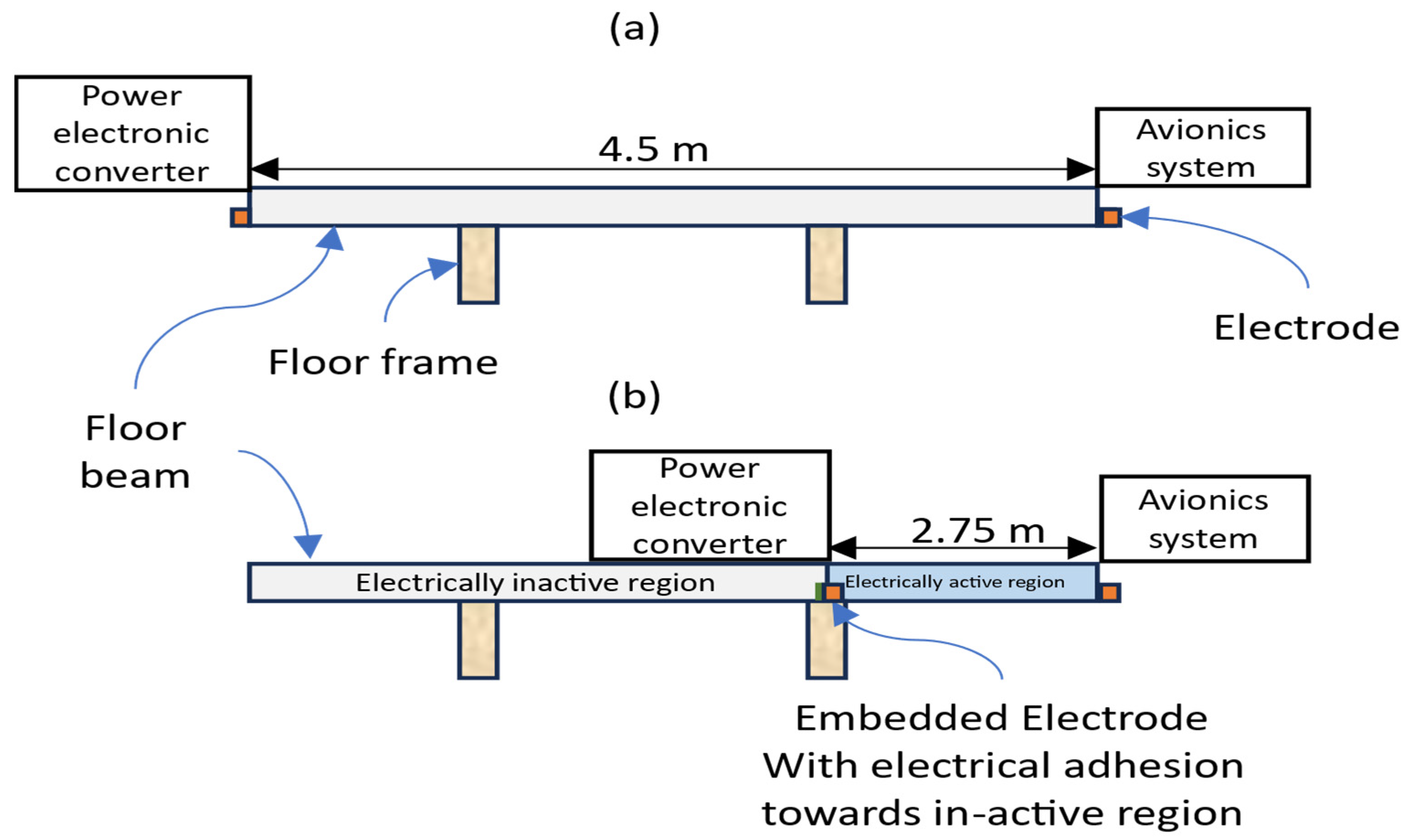
16 stacking sequence met the required electrical and thermal properties. In Step 3A, material property data from Database #3 indicated that the initial configuration with electrodes on the side of the component, measuring 5 mm × 4 mm, shown in
Figure 16a, had an
RCFRP of 3.3 Ω, exceeding the
Rallowable of 915 mΩ defined in Phase-1. To reduce
RCFRP within allowable limits, Iteration I3A was initiated. The first refinement considered adjusting CFRP design factors without altering EPS parameters. Therefore, electrode width size was increased from 5 mm to 50 mm, which reduced
RCFRP to 1.1 Ω, still above the limit of 915 mΩ. Since no further non-disruptive design factors were identified, the second refinement considered EPS-level parameters. One option was to increase the voltage to 45 V
DC, which was rejected due to incompatibility with standard EPS voltage levels. An alternate refinement involved repositioning the electrical equipment within the aircraft to reduce the electrical conducting path from 4.5 m to 2.75 m, reducing
RCFRP to 875 mΩ. To maintain structural strength while limiting the conduction path, the floor-beam was assumed to remain a continuous CFRP structure. Instead of segmenting the beam, electrodes were inserted internally to define a 2.75 m electrically active region (
Figure 16b). This region was positioned near an existing floor-frame support to allow structural load transfer and minimise mechanical risk at the electrical connections. This approach assumes that the joint between electrically active and inactive sections is mechanically bonded and electrically isolated. Electrical isolation is assumed to be achieved using insulating film-adhesives to prevent undesired current propagation into the inactive section. While this assumption supports continuity in the case study, future work should investigate the practical implementation of the isolation method and integration with aircraft floor framing. Step 3D calculated
Ri of 7.5 mΩ. In Step 3E,
Ts was estimated as 38 °C for a rated current of 1.07 A. The assessment assumes that the
Ts will remain significantly below the resin’s
Tg, and the temperature-induced variation in electrical resistance will be negligible over time.
Step 3F calculated the required electrical conductivity (σ) in the longitudinal direction of CRP, based on Ri, using Equation (5). The resulting value of 16,500 S/m was passed to Phase 4 in Step 3G.
In Phase 4, Step 4A, the mechanical, electrical, and thermal requirements were compared with available CFRP options listed in Database #4. In Step 4B, the comparison identified IM7-8552 prepreg as a suitable material meeting all required properties. Hence, in Step 4C, IM7-8552 was selected for manufacturing consideration in Phase 5.
Phase 5 assessed the manufacturability of the selected stacking sequence and material system. Given the flat geometry and need for controlled orientation, the Automated Fibre Placement was selected as the appropriate layup and curing method.
6. Discussion
The methodology presented in this paper offers a structured and adaptable approach to the design and selection of MF-CFRP components for aerostructures with structural and electrical functionality. It facilitates decision-making to achieve MF-CFRP solutions meeting mechanical, electrical, and thermal requirements. A key contribution of the methodology is its ability to adapt to the material and system levels. When initial design configurations fail to meet multifunctional requirements, the methodology enables iterative refinement of CFRP design parameters and system-level factors to reach a viable MF-CFRP solution. By enabling the substitution of separate electrical and structural elements with integrated MF-CFRP components, the methodology supports broader objectives of improving aircraft power density.
The validation of the approach within the methodology was carried out through an expert review (
Section 4). In review, specialists from NMIS evaluated the clarity, logic, and practical relevance of each phase based on their industrial experience.
The adaptability provided by the methodology to adjust CFRP design or requirements to reach an MF CFRP solution was demonstrated through a case study. A 28 VDC system was selected as a representative, low-voltage aircraft EPS. In the case study, modifications of increasing electrode width and reducing conductor length enabled an MF CFRP-based structural component to provide additional functionality of an electrical cable. These modifications demonstrated the ability of the methodology to iterate to reach an MF-CFRP solution while navigating design trade-offs.
The scope of the methodology is limited primarily by the available data in the datasets. At present, available data support DC and low-frequency AC applications (<1 kHz) where electrical impedance is predominantly resistive. As a result, the methodology cannot yet evaluate MF-CFRP performance in aircraft electrical power systems that use power electronics operating at high switching frequencies. At higher frequencies, additional parameters, such as skin effect, frequency-dependent impedance, and dielectric behaviour, also become significant, which are not captured in the current database. To address this limitation, future extensions of the methodology will incorporate high-frequency electro-thermal modelling to enable MF-CFRP within power electronics components with high switching frequencies. These extensions would affect Phase 1 (requirement capture) and Phase 3 (electro-thermal assessment).
While engineering decisions are influenced by development timelines and certification cycles, these factors are not incorporated into the methodology at this stage. The initial methodology aims to establish how multifunctional requirements can be combined with material selection from a technical and functional perspective. Programme-driven considerations, such as certification timeframes, qualification intervals, and production planning, occur after technically feasible MF-CFRP options have been identified and can then be evaluated in subsequent design stages. In the longer term, there is an opportunity to investigate how these programme-level elements may feed into the requirements and iterations within the methodology during early material selection.
The methodology, currently, does not exclusively address the design of MF-CFRP for high-frequency electromagnetic interference shielding or lightning strike protection. These functions require information on properties of surface conductivity or shielding effectiveness that are not addressed in the current material database. Similarly, long-term durability factors such as hygrothermal ageing, UV degradation, and repairability can also be considered, but require a supplementary dataset. To address these, future iterations require the population of databases with missing datasets.
At present, the methodology needs an electro-thermal properties database (Database #3), which contains a limited dataset due to its dependence on experimental work. Incorporating modelling tools, such as FEA, to assess CFRP properties (e.g., electro-thermal response) could reduce this dependence and improve scalability. These modelling tools could be embedded in Phase 2 (for determining stacking sequence) and Phase 3 (for estimating electro-thermal requirements), providing a broader design space. The methodology provides a structure for the design of future experiments and modelling to gather relevant datasets for the wider design of MF-CFRP components.
Although Phase 5 addresses manufacturing compatibility (layup and curing method), as demonstrated in the case study, the methodology does not currently include production rate or scalability as a selection requirement. These factors are important for the commercial feasibility of MF-CFRP components. The challenge in incorporating them lies in the lack of reference data linking material design to manufacturing data and production cost. Addressing this would require the development of a dedicated database capturing process-specific parameters. This database could be integrated into Phase 5 to evaluate trade-offs between CFRP properties, manufacturability, and scalability.
Material requirements of chemical durability, repairability, and resistance to environmental degradation are not considered in the methodology. These factors influence the long-term viability of MF-CFRP components under operational conditions involving moisture, UV exposure, or in-service damage. These considerations could be incorporated into Phase 1 (requirement capture) and Phase 4 (material selection), supported by datasets on long-term property retention (e.g., aged ILSS and moisture absorption). The challenge is the collection of long-term test data, which is typically costly and specific to individual CFRP systems.
7. Conclusions
This paper has presented a methodology for the design and selection of MF-CFRP that combines structural and electrical power functionality for application in aircraft electrical power systems. The following key conclusions can be drawn:
Methodology development: Unlike existing material selection methods, this methodology enables the design and selection of MF-CFRP components with combined mechanical, electrical, and thermal properties. It provides a structured process supported by database-driven inputs and iterative refinements. A key contribution of the methodology is its design adaptability. If a solution cannot be reached, it provides an approach to improve CFRP properties or adapt system-level requirements to reach a solution. This adaptability changes the process from a static material selection method into a multifunctional design and problem-solving tool capable of navigating trade-offs and supporting the development of MF-CFRP components for aerospace systems.
Validation and Demonstration: The methodology was validated through expert review, which confirmed the completeness, correctness, and industrial relevance of each phase of the methodology. The case study demonstrated how the methodology manages design refinements and identifies feasible design pathways to meet requirements.
Limitations of the methodology: The current scope of the methodology is limited by the availability of data within the supporting databases, particularly for electro-thermal properties (Database #3). As a result, MF-CFRP configurations that rely on missing or incomplete datasets cannot be fully assessed within the current framework. However, this limitation also identifies a useful outcome of the methodology and reveals promising MF-CFRP opportunities for which data is not yet available. This highlights the need for targeted experimental work or focused material characterisation.
The methodology also does not incorporate production rate constraints, detailed cost considerations, or programme-driven factors such as certification timelines and qualification intervals, all of which influence industrial adoption. These aspects fall outside the scope of the early-stage selection process supported by the methodology but remain important in determining whether an MF-CFRP solution progresses further in a development programme.
- 4.
Role of FEA and Machine Learning: Future work may also include the use of modelling approaches to enhance the methodology. FEA could offer a route to estimate electro-thermal behaviour in cases where experimental datasets are incomplete. In parallel, there is an opportunity to investigate machine-learning methods that could draw on existing mechanical, electrical, and thermal data to predict properties for new CFRP material systems. Together, these approaches could support early-stage screening and improve the scalability of the methodology by enabling exploration of the multifunctional design space without requiring comprehensive experimental work.
- 5.
Expansion of functional and environmental datasets: Future datasets are needed to capture high-frequency impedance, dielectric behaviour, frequency-dependent current distribution, moisture-conditioned mechanical/electrical properties, UV ageing effects, repairability, EMI shielding effectiveness, and lightning strike protection. These datasets will enable the methodology to address the full multifunctional and long-term performance envelope required for aerospace CFRP components. This will also enable the methodology to support high-frequency aircraft electrical architectures where switching frequencies influence electro-thermal response.
- 6.
Development of design tool: A key future step is translating the methodology into a digital MF-CFRP design and selection tool. This will require preparing the existing material datasets for use within a digital design tool and formalising the iteration logic between phases. It will also require integrating FEA and machine-learning models into an interactive environment. This will enable a real-time assessment of manufacturability, electro-thermal constraints, and system-level compatibility of the MF-CFRP solution.
With the above-mentioned improvements, the methodology will evolve into a comprehensive, scalable framework capable of guiding MF-CFRP design and selection. These improvements will, hence, support the aviation needs for higher-power-density structural–electrical components to develop full-electric aircraft.