1. Introduction
The temporomandibular joint (TMJ) can be affected by severe pathologies such as arthritis, tumors, or ankylosis, leading to major functional impairment and pain. Considering diseases with a high degree of severity, prosthetic substitution of the articulation is indicated. In recent times, the frequency of this surgery has been rising due to the increase in the aging population and its functional benefits and low morbidity [
1,
2]. According to the FDA, approximately 5500 TMJ total joint replacement procedures were performed in the U.S. from 2005 to 2014 and the number of implanted TMJs is going to grow by a further +58%, from 2014 to 2030 [
3,
4]. In Europe, the only working registry is in the UK and it reported about 577 implants between 1994 and 2012 [
5]. Total joint replacement requires the implementation of two main components, the fossa and the condyle [
6]. These prosthetic elements are connected, respectively, to the cranium and the natural or prosthetic mandible ramus.
Many solutions have been developed over time, mainly differing in the materials employed and in the design.
Dealing with the materials, a general consensus has been reached: the mandibular component is commonly built from a metal alloy, such as Ti-6Al-4V titanium [
7] or Co-Cr-Mo (cobalt–chromium–molybdenum) [
8], owing to their high strength, fatigue and corrosion resistance; the fossa, as a low-friction articulating surface, is made with ultra-high-molecular-weight polyethylene (UHMWPE) [
8], eventually coupled to a metal plate for bone fixation. Some new perspectives might be opened up by new polymers such as polyetheretherketone (PEEK) and polyetherketoneketone (PEKK), due to their favorable mechanical properties, in particular an elastic modulus closer to that of bone, and better biocompatibility compared to UHWMPE [
9]. The use of these materials is still under investigation, considering these polymers are biologically inert and do not promote osteointegration; in addition, their respective wear performances have yet to be definitely established and long-term evidence for their clinical performance remains limited [
10].
Dealing with TMJ design, some main guidelines have been established since moving from the hinge concept [
11], where one single planar rotation (pitch) was allowed, to more incongruent joints (such as a sphere/cylinder on a plane [
12,
13] or on curved surfaces), up to joints where rotations along all three main axes are freely combined with translation along the antero–posterior direction [
14]. This was also made possible thanks to the widespread use of 3D-printing technologies which have dramatically widened the range of available geometries [
1,
2]. In view of the extended technological capabilities, it is increasingly important to establish criteria for the design of articular surfaces. These criteria should account for the degree of concavity or convexity and the depth of the fossa, which together influence the stability of the support. Additionally, they may include built-in movement limitations, or “stops”, in one or more directions (anterior, posterior, buccal, or lingual).
General considerations can be joined to patient-specific ones, to obtain not only a precise fitting to the residual bone through detailed preoperative imaging [
15], but also the optimal recovery of physiological movement. Finally, further specifications can be given, concerning surface finishing (such as lattice or honeycomb structures [
16,
17]) for optimal osteointegration and the possibility of muscle attachment [
18,
19,
20].
This research work aims to make a contribution towards setting up criteria for patient-specific TMJ surface design and optimization. More traditional methods, based on empirical design and guided by anatomical considerations [
8] followed by post-validation through finite element analysis (FEA) [
11], limit the customization primarily to the design of the interfaces between the prosthesis and the bone. In this work, the customization also includes the articular surface and the application of traditional methods and here it is preceded by the experimental recording of real-time kinematic data from 3D mandibular tracking, along with multibody (MB) modelling [
21] of the bone–prosthesis system. The use of an MB approach entails consideration of the actual position of the prosthetic joint axes, which are generally lower compared to the physiological ones, leading to a design of articular surfaces that might be different from the physiological ones. The final objective of a prosthesis design is to optimize the biomechanical performance in terms of recovery of the physiological movement path, allowing a range of movements, minimization of the required muscle force and resulting joint contacts, also minimizing wear, which represents one of the main reasons for prosthetic joint failure [
22].
This research aims not only to develop customized prostheses but also to highlight the significance of aligning joint design with individual anatomical and functional requirements, ultimately improving clinical outcomes for patients.
2. Materials and Methods
The procedure to optimize the articular fossa surface based on patient-specific anatomy and kinematics is illustrated in
Figure 1. The patient’s anatomy is obtained from a CT scan through bone segmentation, while the kinematics is recorded using an optical jaw tracking system. The above reported information is provided as input to a multibody model to optimize the fossa design based on contact forces and the accurate reproduction of physiological motion. The multibody model has been tested on two empirically designed fossae as a benchmark to assess its ability to discriminate between the performances of different designs. In the next step, the whole workflow has been implemented iteratively to reach an optimized design.
In the following, the details are provided for each step of the workflow.
2.1. Subject-Specific Anatomy
The STL files of the mandible and skull, derived from the segmentation of CT scan data, were provided by the collaborating clinicians as rigorous anonymous data.
The native skull and the mandible bones were used for the implementation of the original movement of the patient, in what will be called a “physiological model” in the following: both the mandible and the maxilla geometries are then modified through virtual surgery, for the implementation of the “prosthetic model”. A complete resection of the left side was simulated here, as required for certain tumor resections.
2.2. Mandible Movement Tracking
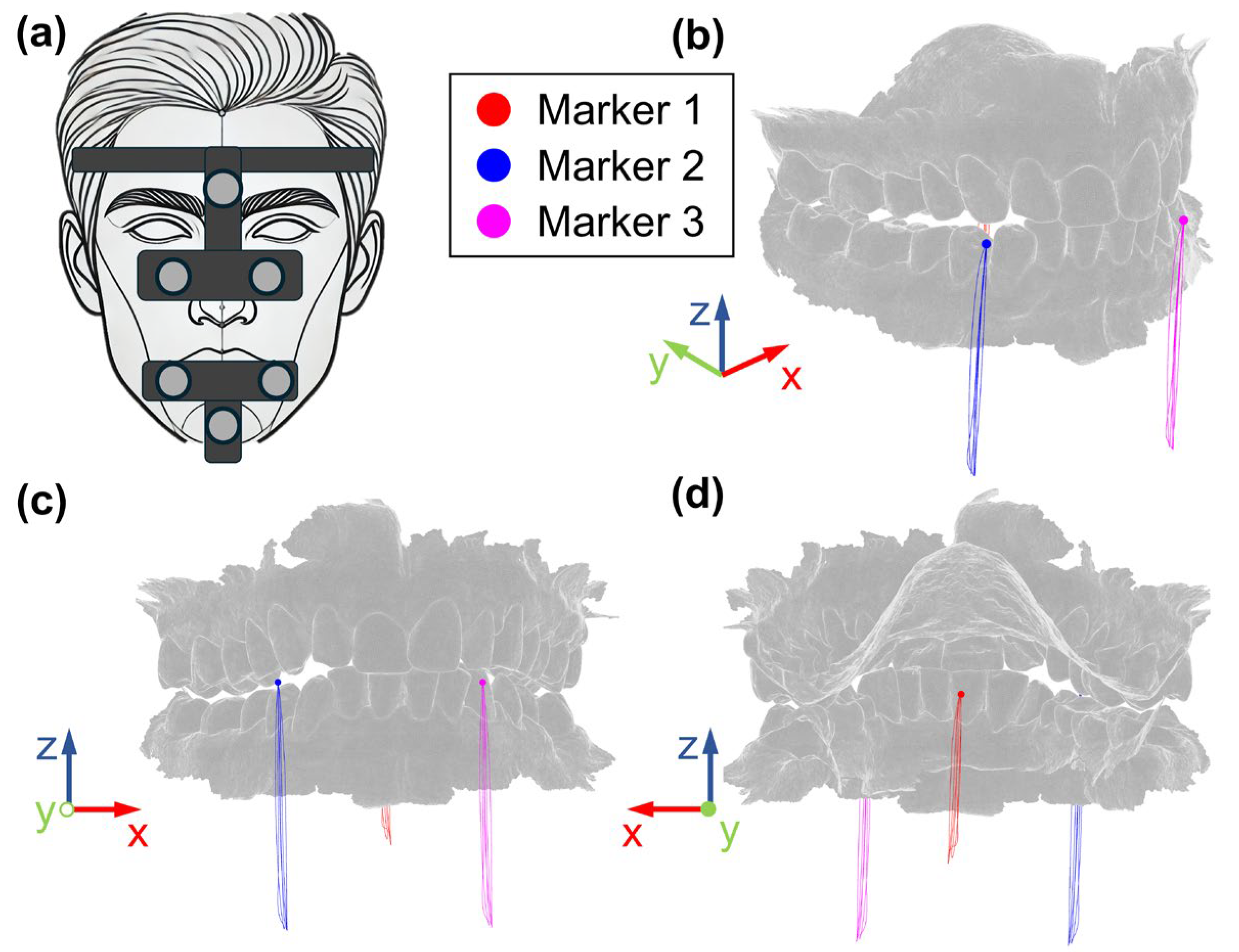
Opening and closing movements of the mandible have been recorded using the Cyclops optical jaw tracking system (ITAKA WAY MED SRL, Venice, Italy) [
23]. The system uses six markers to track mandibular movements (
Figure 2a); three markers are attached to the skull through an “Upper Positioner”, while three markers are fixed to the mandible using a “Mandifork”. The system outputs a .txt file containing information about the three-dimensional coordinates of three marker points, obtained with respect to a fixed reference system, fixed on the skull where the x-axis represents the medio–lateral direction, y-axis the anterior–posterior and the z-axis the superior–inferior direction. Two front marker points are placed in correspondence of the maxillary canine teeth mandibular central incisors, and one marker point is placed in the center of the palate.
The subject was required to perform the maximum opening and closing of the mouth, starting and ending at the intercuspidal position.
2.3. The Multibody Model
The multibody model was implemented through ADAMS multibody software (Hexagon software, rel. 17).
All the system elements (the bones and the prosthesis) were modelled as solid bodies, having considered that the aim of this study was to assess how the global kinematics of the system is impacted by the TMJ design.
The subject-specific maxilla and mandible geometries were directly imported into the software as obj file format.
The prosthesis is made by two components that are the fossa, which is a unique component that connects directly to the bone, and an artificial condyle. All these parts were designed in SolidWorks CAD software (v. 2023) and imported as step files. These components are made of polyethylene (fossa) and titanium (artificial condyle) and the corresponding density values were implemented into the model (925 kg/m
3 and 4506 kg/m
3, respectively). The geometry of the prosthesis will be discussed in detail in
Section 2.4.
Dealing with boundary conditions, the skull was fixed to the ground since the tracking system outputs the mandible movement with respect to the skull; the fossa component was fixed to the skull and the artificial condyle was bound to the prosthetic mandible.
Three markers were identified on the mandible, at locations corresponding to the actual position of Cyclops system landmarks.
Movements recorded by ITAKA Cyclops were then applied to these markers to replicate the actual movement of the subject. The red, blue and magenta points reported in
Figure 2 represent the initial positions of the markers, while the lines represent the trajectories recorded by the tracking system, in terms of the respective coordinates x, y and z. As is well known, the mandible, which acts as a solid body moving in 3D space, has six degrees of freedom; therefore, assigning 9 coordinates (three for each marker) would lead to an over-constrained system, running the risk of incompatible inputs because of small experimental errors and misalignment between experimental and numerical markers (due, for example to skin movement with respect to the bone). This is the reason why the three markers were connected to the mandible through bushing elements (six component elastic elements) which realize labile constraints. Different combinations of bushing parameters were tested, and the following values were finally selected: 10 N/mm for the linear stiffnesses, 0.1 Nmm/° for the rotational stiffnesses and 0.1 Ns/mm and 0.1 Nmms/° for damping. With this combination of parameters, the maximum deviation between experimental and numerical trajectories was observed on Marker M1 (
Figure 2) along the
z-axis (vertical movement) and reached 0.47 mm at the maximum mouth opening.
Contact forces were implemented between the skull and the mandible in correspondence with the fossa region both for the physiological and the prosthetic joint to obtain qualitative information about contact behavior. At this stage, this estimate has no quantitative value because a soft contact was implemented (through IMPACT formulation) with the purpose of prioritizing the replication of physiological movements: a stiffness equal to 100 N/mm2.2 was set (presumably lower than the actual one), a damping coefficient of 10 Ns/mm, a force exponent of 2.2 and a penetration depth of 0.1 mm. Criteria to set these values are further detailed in the following paragraph, referring to “fossa design optimization”.
Mouth opening was measured in terms of the opening angle, which will be used as an independent variable for results post-processing.
2.4. Preliminary Prosthesis Designs
Two preliminary anatomy-based designs of the prosthesis were considered as a benchmark, they are named “Compact Design Fossa” (CDF) and “Enhanced Design Fossa” (EDF) in the following. These designs differed both for the fossa and the condyle geometries, and their respective performances were compared with each other and with the physiological model. The prosthetic ramus of the mandible was common to both devices and it was designed based on the contralateral healthy bone, mirrored and then trimmed to match the residual chin bone and the prosthetic condyle geometries.
2.4.1. Compact Design Fossa (CDF)
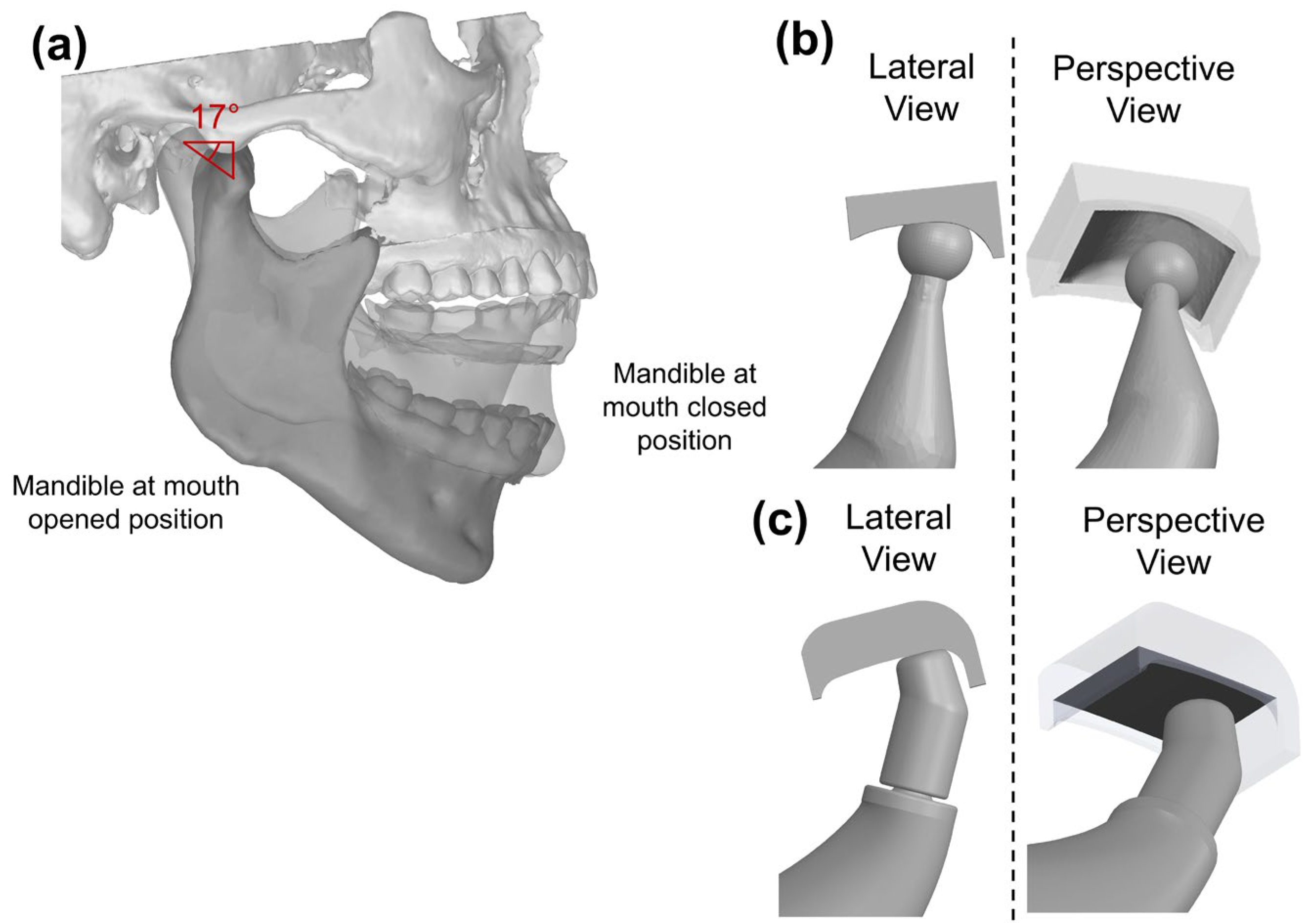
The compact design fossa (CDF) includes an articular surface 16 mm × 12 mm (
Figure 3b), as substitute for the natural fossa. This block is characterized by a semi-cylindrical concave cutout on the bottom face, smoothly curved to mimic the natural curvature of a TMJ fossa. The compact nature of this design results in limited bulk volume and material required for manufacturing.
As for the prosthetic condyle, this was assigned a spherical design, with a diameter equal to 7.5 mm, approximating the size of a natural condyle.
2.4.2. Enhanced Design Fossa (EDF)
The second articular surface design is larger than the CDF, with the respective length reaching 21.5 mm, and a width of 16 mm (
Figure 3c). The EDF incorporates a cutout as CDF, coupled to a planar surface that is larger and deeper. The EDF was mounted with 17° inclination angle to match the natural motion of the TMJ; indeed, this inclination angle was established tracking the condyle movement during the opening and closing of the mouth (
Figure 3a).
Anterior/posterior stops were augmented, to prevent condyle dislocation.
A different condyle design was used for the EDF: this design was cap-shaped with a diameter of 8 mm perpendicular to the articular surface
Figure 3c. The prosthetic mandibular ramus was the same as for the CDF solution.
2.5. Metrics for Ranking the Fossa Design
Both prosthesis designs were implemented into the MB model, and some metrics were established to rank and then optimize the fossa design.
The first metrics concerned kinematics: the peak antero-posterior and medio-lateral displacements and the peak rotation in the sagittal plane were assessed; the absolute reference system defined in
Figure 2 was used for that purpose. This was the first indicator of rehabilitation performance since the main objective is recovering the full mobility of TMJ [
24] and guaranteeing the same opening angle as in the native joint. Moreover, it should be considered that whenever physiological movements are hampered, prosthesis-to-bone connections are stressed leading to the risk of dislocation [
25] or loosening [
26].
A second metric was calculated based on contact force estimation, referring to the physiological joint as a reference. As is well known, the contact forces play a vital role in designing fossa structures that must be able to withstand physiological loads without causing undue stress or wear [
27], as these can lead to complications such as implant failure or adverse biological reactions [
28]. The same contact parameters were set for both models and contact forces versus mouth opening angle were considered.
2.6. Fossa Design Optimization
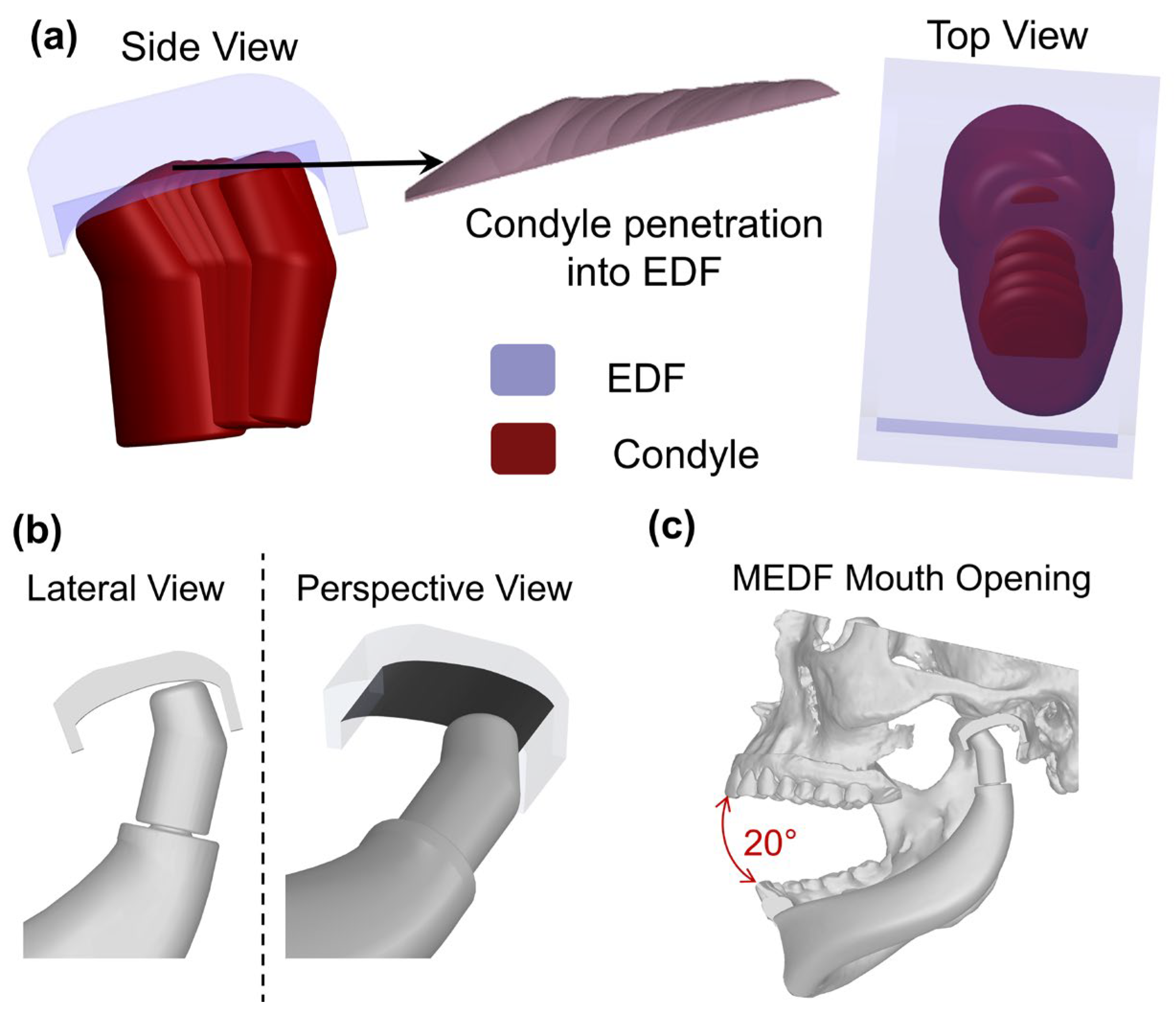
One main element in fossa design is the articulating surface, since it works as a guide and, at the same time, it must not undergo high stresses in order not to incur wear. According to a simplistic assumption, the ideal design is the one replicating the physiological articular surface. Nonetheless, this would be a rough approximation for two main reasons: the absence of the articular disk and the different position of the articulating surface. This is the reason why a different strategy has been implemented here.
The envelope of the interference volume between the condyle and the fossa is used as a design tool to obtain the ideal shape of this surface in relation to condyle design and physiological mandible motion. This provides a single output for each full opening/closing cycle.
Considering that we are working with rigid bodies, no deformation occurs during contact, but a certain penetration between geometries does exist and it depends on the contact stiffness; if a very soft contact is assumed, the mandible is free to perfectly replicate the physiological movement and to virtually “dig” its own seat. Nonetheless, some additional boundary conditions need to be considered: first, the thickness of the fossa cannot fall below a given thickness (this limit was here set equal to 5 mm) which would make it too weak and too prone to be quickly worn out. Secondly, enough bone stock should be preserved to allow a secure bonding of the fossa. The contact stiffness was tuned according to these two limits, and finally the envelope of the intersection volume between the fossa and the condyle was used to modify the fossa design through a Boolean subtraction. This operation was repeated iteratively up to the convergence of contact force values.
4. Discussion
This study introduces a novel methodology centered around the creation of TMJ surfaces that optimize biomechanical performance, with the main aim of restoring the physiological behavior of the joint. Real-time kinematic data from a patient’s 3D mandibular tracking were used, along with a multibody model [
21], to design an optimal patient-specific shape for the articular surface. The main assumption is that the prosthesis is part of a biomechanical system, made of muscles and ligaments, which is intended to produce given kinetics. When physiological movements are restricted, components of the artificial joint, such as the articular surfaces or their attachments to bone, can become overstressed, leading to excessive wear [
22]. This, in turn, may result in bone loosening [
29], osteolysis [
30], or prosthesis mobilization [
31], which are the main causes of prosthetic TMJ failure over time.
The opening and closing functions were specifically chosen for this study because they are performed approximately 1500 to 2000 times per day [
32] and involve the widest range of motion. This high frequency of movement encompasses essential daily activities such as speaking, swallowing and yawning.
As a further step, the authors tried to establish quantitative criteria to compare different design solutions; these were intended to assess the width of allowed motions and the contact forces at the articular surfaces.
Preliminary trials on a specific patient demonstrated the need for the antero–posterior length for the fossa component to be above 13 mm (reaching 22 mm total length when the posterior and anterior stops’ thicknesses are added) in order not to incur the risk of mandible dislocation (in the case of the absence of an anterior stop) or into repeated stressing of the fossa fixture (in the case of the presence of an anterior stop [
33]). According to this finding, some designs found in the literature would deserve further attention in cases where full physiological motion is intended to be re-established [
24,
34,
35].
As is well known, the joint system needs to be labile to accommodate the variety of movements recorded during mandible tracking [
36]. This mobility can only be achieved by making use of incongruent articular surfaces; this is the reason why the addition of anterior and posterior stops is highly recommended [
21], even if, as previously noted, these stops should exert their actions only under extreme conditions to avoid excessive stress on the fossa fixture, which could eventually lead to mobilization and loosening [
29]. This concern arises from the fact that often ligaments cannot be restored after surgery and therefore the respective restraining function is lacking [
37,
38].
The method introduced here for a patient-specific fossa design relies on calculating the envelope volume covered by the intersection between the artificial condyle and the fossa and iterating this procedure up to the convergence of the calculated contact forces (
Figure 5). A parametric study was conducted to determine the appropriate number of frames to be considered for the assessment of the envelope volume, by continuously adding intermediate frames up to the point that the number of frames no longer impacted the overall volume. If this procedure were to be followed simply by making use of 3D CAD models, an unrealistic solution would be found with minimum or null fossa thickness. The reason is that the design of the fossa is not completely free due to anatomic constraints, since it must interface with residual bone; in addition, a reasonable thickness must be guaranteed [
39], which most often leads to the positioning of the artificial joint being lower compared to the physiological one [
31]. This is the reason why a patient-specific multibody model, able to assess contact forces between bodies, needs to be used. The result obtained in
Figure 5 represents a viable solution, since it minimizes the amount of bone to be removed and it provides a minimum thickness above 5 mm.
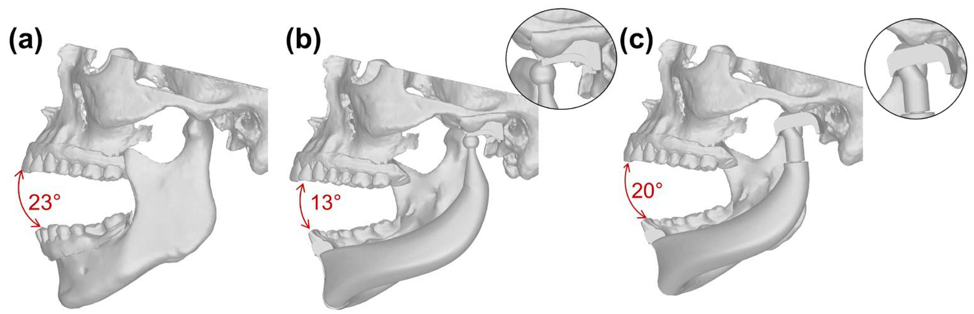
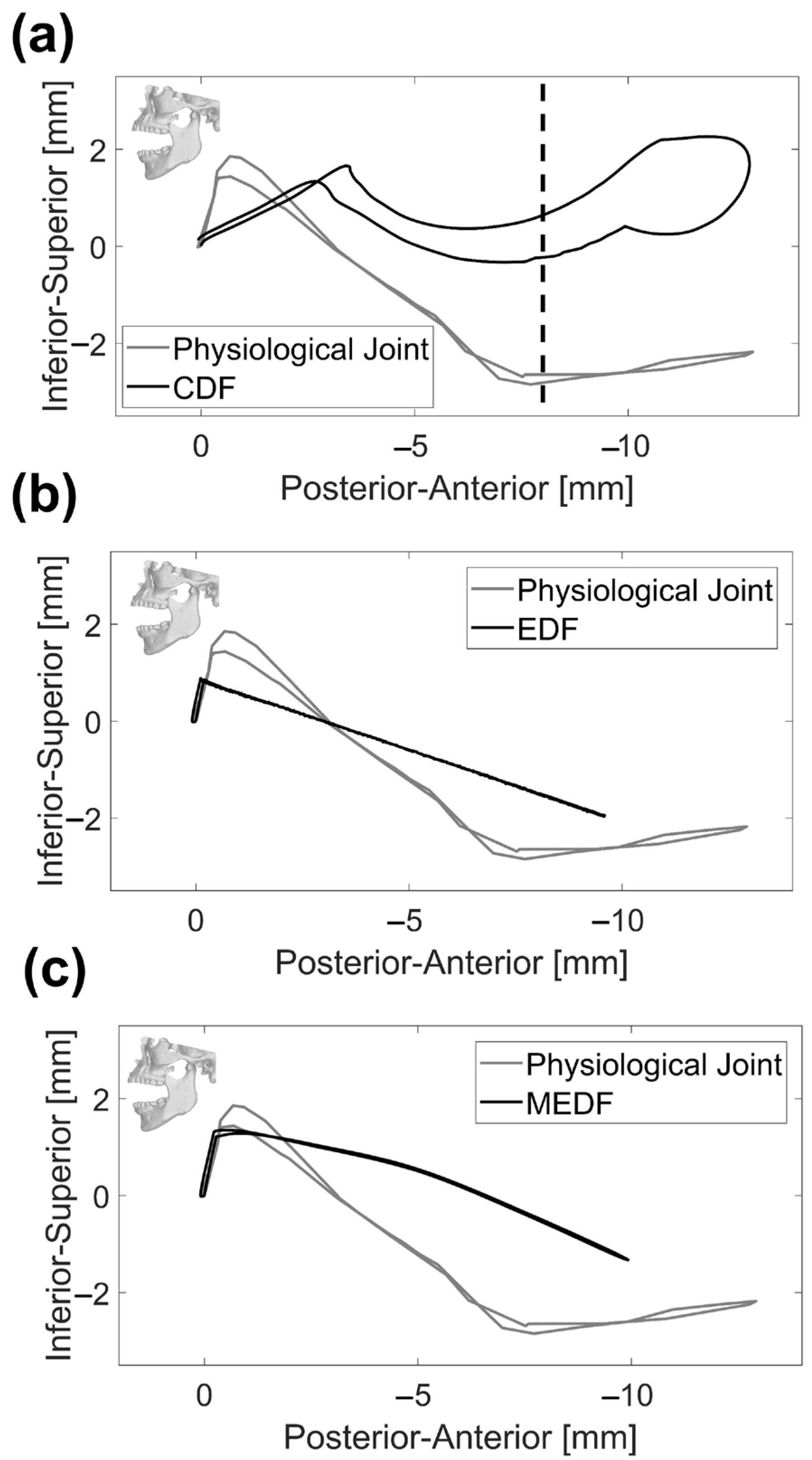
Looking at the displacement results reported in
Figure 6, it is evident that replicating the initial inclination of the condyle’s path in the sagittal plane is critical to accurately mimic the physiological mandible movement [
40]; this assessment needs to be made on each patient, given the physiological variability in this angle among subjects. Looking at the lateral view in
Figure 6, major emphasis should be put on the very initial part of the curve that is of interest for masticatory movements: in the CDF, the inferior–superior movement is coupled to a pronounced antero–posterior movement which could hamper the correct occlusion required for mastication; the EDF is affected by a very limited inferior–superior excursion and this could be an issue, since the full range of intercuspidal displacement is not exploited; MEDF behavior is very close to the physiological one, offering the possibility of replicating physiological mastication. Looking at the whole movement, indeed the physiological joint undergoes a wider excursion along the inferior–superior axis (30.2 mm versus 29.6 mm in MEDF); this could have implications on the maximum achievable mouth opening of prosthetic solutions, in terms of vertical displacement. The reason for this minor impairment is related to the envelope volume of the fossa which, as said above, cannot be reduced beyond the limit set by the need to provide an adequate articular surface thickness [
39].
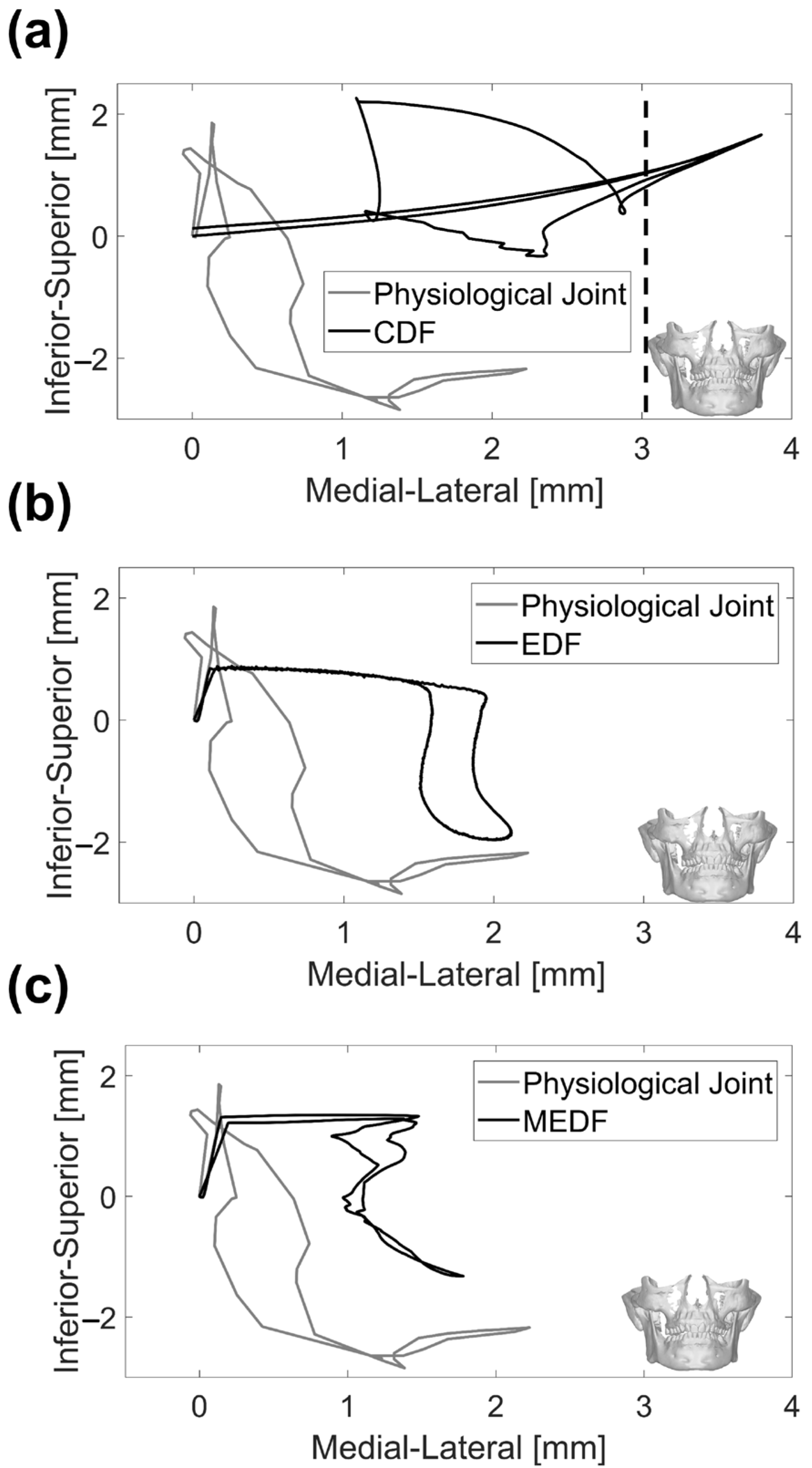
Figure 7 offers some other interesting information also in relation to medio–lateral movement: this movement is exacerbated in CDF, because of instability and possible dislocation also along this direction; MEDF and even better EDF, allow the full range of movement along this direction as required for grinding actions.
The implementation of the MEDF design led to a complete recovery of the original range of motion; indeed, the condyle displacements and the mandible rotation resulted in an interincisal opening of 29.2 mm, comparable to the physiological one (30.6 mm). These results agree with those obtained with existing TMJ devices. The TMJ Concepts/Techmedica and Biomet stock systems represent two of the most implanted and investigated prosthesis. Follow-up studies on these devices [
41,
42] have proved that both are able to recover the full range of motion, or increase it if the patient was affected by mobility limitations. The main step forward in the methodology here presented is related to the combined use of recorded-motion data and a numerical model, along with a complete customization of the prosthesis design. Indeed, customization of TMJ devices is typically limited to shaping the titanium sheet to fit the anatomic fossa surface and modifying the patients’ remaining mandibular bone to accommodate the prosthesis. Moreover, the system’s assessment is made only by performing mock surgery on a 3D-printed model or virtual models of the mandible and the prosthesis, which limits the possible investigations that can be performed.
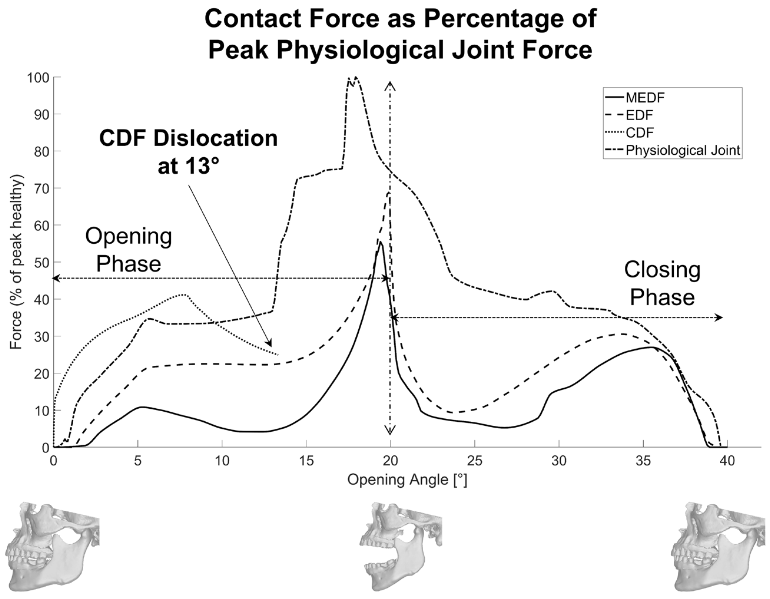
Looking at the relative contact forces reported in
Figure 8, it is evident that the optimized patient-specific design of the articular surface in MEDF produces a significant reduction in their values compared to more conventional designs, such as CDF and EDF: not only is the peak value reduced, but also the standard deviation of the contact force; this is beneficial since wear is the main cause of failure in these protheses.
The whole procedure here was setup and tested on one single subject, the main aim of the work being to clarify how patient-specific data can be used and the benefits coming from following this approach. A more robust validation with data about geometric variability when covering a full population will be reached when more patients are analyzed. Nonetheless, the proposed approach can be directly extended to any subject, starting from the specific reconstructed anatomy and recorded-motion data. Based on the CT scan data, the geometry of the prosthetic ramus can be updated based on specific anatomical constraints, as well as the inclination of the fossa component, that in this study was set to 17°, and is dependent on the glenoid fossa geometry. The possibility of recording mandible motion gives the possibility to assess the recovery of mobility.
At the present stage, the muscle force needed to produce movement has not yet been calculated, and this could give one further metrics by which to compare the different design solutions, eventually also providing hints for surgery, and more specifically to determine muscle attachment sites in view of the new position of the joint on the prosthetic side [
37].
The contact parameters have been tuned here to reach an optimized design, compatible with anatomic constraints; when this same model is used to evaluate muscle forces, realistic contact properties will have to be implemented and validated [
43,
44].
Future activities will be devoted to increasing the complexity of the model, creating a hybrid MB-FE model, to consider also the elasticity, friction and wear properties, as well as to increase the accuracy of the contact modelling. In fact, having set the optimal geometric design, equal attention must be paid to the accurate selection of materials with the requisite elastic, viscous and friction properties, in view of wear issues, biocompatibility and strength. For this, more detailed models, especially of the articular surface, will be required, considering the local deformability and pressure distribution, making use of finite elements. All these are indeed key parameters for the assessment of the working life of the prosthesis and need to be assessed to make the prosthesis market-compatible.
The methodology introduced here is an attempt to provide a rationale for the design of patient-specific total TMJ and to perform numerical pre-clinical testing. As reported above, further numerical tests are still necessary, based on finite elements, as well as experimental tests which remain necessary, especially for assessing wear behavior [
45]. All that said, only clinical outcomes, measured in the long-term will provide definite evidence of the validity of this new approach and design.
5. Conclusions
This study aimed to set up a methodology for a patient-specific design of TMJ prostheses, moving from the consideration that patient-specific design cannot be limited to the interface between the prosthesis and the bone, and should include also the articular surface of the fossa to restore the natural condylar kinematics effectively, making use of mandibular tracking data.
Several key points have been established: the optimal size of the articular surface of the fossa can be assessed from patient-specific kinematics data; its inclination should replicate the patient’s native inclination; the shape and thickness of the articular fossa must strike a balance between replicating the physiological motion and accommodating anatomical constraints. This balance also takes into account wear issues, which specifically affect prosthetic components that lack natural lubrication.
The patient-specific design, implemented in the MEDF, demonstrated superior adaptability and stability, by achieving a mouth opening angle of 20° and maintaining uniform loading throughout both opening and closing phases rather than exhibiting large peaks or drops (26% of peak physiological force). The MEDF’s unique U-shaped design and anterior stop feature contribute to preventing any dislocation while guaranteeing smooth condyle movement with limited peak forces. In contrast, the EDF, designed with a more conventional, non-patient-specific articular surface, offered a higher variability in contact forces. Both designs met the necessary criteria for effective TMJ reconstruction, but the MEDF offers smooth condylar translation and lower joint forces, making it a promising option for improved rehabilitation outcomes and greater durability for the prosthesis.


 ,
, 


