
Article

Crashworthiness Optimization of Composite/Metal Hybrid Tubes with Triggering Holes
1
FAW Global R&D Center, National key Laboratory of Advanced Vehicle Integration and Control, Changchun 130013, China
2
CATARC (Tianjin) Automotive Engineering Research Institute Co., Ltd., Tianjin 300000, China
*
Author to whom correspondence should be addressed.
Designs 2026, 10(2), 44; https://doi.org/10.3390/designs10020044
Submission received: 14 January 2026 / Revised: 27 March 2026 / Accepted: 7 April 2026 / Published: 10 April 2026
(This article belongs to the Section Vehicle Engineering Design)

Abstract

Due to high specific energy absorption, composite/metal hybrid multi-cell thin-walled tubes hold significant potential in the field of automotive passive safety. However, the material coupling effect enhancing SEA often elevated the initial peak crushing force, reducing crushing force efficiency and compromising occupant protection. To balance SEA and CFE, trigger holes were introduced as an induced deformation mechanism for hybrid tubes to reduce IPCF while preserving SEA, with the optimized perforated configuration yielding higher CFE than the non-perforated counterpart. A high-fidelity finite element model of the hybrid tube was developed and experimentally validated, and the influences of induced structural parameters on SEA and CFE were investigated. Given the strong nonlinear coupling between trigger parameters and crashworthiness, a multilayer perceptron surrogate model was constructed using 200 optimal Latin hypercube sampling samples (20 for validation). A Q-learning enhanced particle swarm optimization (QL-PSO) algorithm was adopted for optimization, with reinforcement learning dynamically adjusting PSO parameters to balance global exploration and local exploitation. Finite element simulations validated that the proposed method achieved a favorable SEA-CFE trade-off, with SEA and CFE improved by 12.02% and 16.39% respectively, outperforming reported configurations. Compared with standard PSO, QL-PSO exhibited superior search efficiency and inverse mapping accuracy, with 22% higher optimization efficiency and full compliance with inverse design performance targets. This study provided valuable guidance for the design of thin-walled energy-absorbing structures in multi-material vehicle bodies.

1. Introduction

Carbon fiber-reinforced polymer (CFRP) and aluminum alloy hybrid structures, such as CFRP/aluminum alloy hybrid tubes (CAHTs) [1], have been identified as key structural solutions for automotive lightweighting and safety enhancements owing to their superior specific strength and energy absorption performance [2,3]. Circumferential constraints could be imposed on multi-cell aluminum tubes by CFRP, which enabled more sufficient wrinkling deformation, while the plastic deformation of aluminum alloy was able to induce the stable failure of CFRP simultaneously. Although such structures exhibited significant application potential for front-end automotive components such as crash boxes, their axial crushing behavior presented an inherent trade-off: multi-cell designs could effectively enhance specific energy absorption (SEA) [4], but they also tended to induce a dangerously high initial peak crushing force (IPCF), which posed a threat to occupant safety. Therefore, the achievement of a better balance between high energy absorption efficiency and high load efficiency remained a core challenge in the field [5].
To reconcile this contradiction, current research efforts were primarily focused on trigger mechanisms [6] and variable thickness designs [7]. Trigger mechanisms, which introduced geometric pre-weakening to guide structural deformation, were regarded as particularly promising owing to their manufacturing feasibility and proven effectiveness in reducing IPCF [8]. However, the introduction of trigger structures into hybrid multi-cell tubes was found to significantly intensify geometric and material nonlinearities. Numerous integrated trigger mechanisms had been developed in existing studies, including chamfer triggers, steeple triggers, tulip triggers, and sawtooth triggers, whose core function was to weaken structural stiffness by thinning the tube’s leading edge or introducing local defects, thereby decreasing the IPCF during compressive loading [9]. Among these, chamfer triggers had emerged as the most widely used conventional trigger type due to their straightforward integration process. The influence of different trigger structures on the crashworthiness of hybrid tubes under axial compression was investigated by Khan et al. [10], and the results revealed that for specimens with chamfer triggers, the IPCF decreased with an increase in chamfer angle; similarly, the IPCF of specimens with double-step triggers reduced as the height of the second step increased. No clear trend was, however, observed in the variation of mean crushing force for specimens with either chamfer or double-step triggers. In contrast, methods such as the introduction of guide grooves [11,12] or trigger holes [13,14] on the tube sidewall were shown to not only significantly reduce the IPCF but also alter the deformation mode of thin-walled tubes. The number and arrangement of trigger holes were found to potentially exert an adverse effect on the overall crashworthiness [15]. A pre-perforated CFRP/aluminum alloy hybrid single-cell tube structure was proposed by Gan et al. [16], which induced the deformation of the entire structure at the perforated locations. Studies on perforation size demonstrated that when the perforation size ranged from 4 to 6 mm, the crashworthiness of the metal/CFRP hybrid tube achieved better load consistency. However, limited research had been conducted on the induction design strategies for metal/composite hybrid multi-cell tubes, and further investigation into the influence mechanisms of their trigger mechanisms need be required.
Beyond the exploration of trigger mechanisms, an optimal balance between the specific energy absorption and crush force efficiency of hybrid tubes was typically achieved through multi-objective optimization design to identify the global optimal solution. In particular, more sophisticated optimization models for metal-FRP hybrid thin-walled tubes could be developed via the integration of the non-dominated sorting genetic algorithm II with the technique for order preference by similarity to ideal solution [17], as well as the combination of backpropagation prediction with the complex proportional assessment method [18]. The response surface methodology (RSM), which established second-order regression equations based on observed data to construct functional relationships between input factors and response variables, had been successfully employed to quantify the influence of crashworthiness parameters on evaluation indicators in hybrid tubes [19,20]. Furthermore, enhanced accuracy of parameter prediction and improved performance of crashworthiness parameter optimization methods could be attained by integrating RSM with radial basis function networks or Kriging [21]. Promising results in the SEA optimization of hybrid tubes had previously been achieved using ANN-based crashworthiness parameter optimization methods (CPOMs) [22], as well as hybrid approaches combining artificial neural networks with RSM [23] or radial basis functions [24]. Meanwhile, the crashworthiness optimization of hybrid tubes frequently involved the application of full factorial experimental design [25,26], as exemplified by the optimization of new hybrid thin-walled automotive bumpers via LS-OPT software [27]. Hybrid multi-cell thin-walled tubes with trigger structures were, however, found to exhibit stronger nonlinear characteristics, which posed significant challenges to the prediction of structural performance and the implementation of multi-objective optimization. Therefore, the systematic elucidation of these influence mechanisms and the establishment of efficient optimization methodologies were crucial for the design of high-performance multi-material hybrid energy-absorbing structures.
To improve optimization efficiency, inverse design had emerged as a promising approach to traditional “forward” trial-and-error processes, which aimed to establish a direct reverse mapping from performance targets to design parameters [28,29,30,31,32]. The implementation of this “end-to-beginning” approach was, however, hindered by two inherent obstacles [33,34]: the prohibitive computational cost of high-fidelity simulations led to data scarcity, and the highly nonlinear “one-to-many” mapping relationship made analytical modeling extremely difficult [35,36,37,38]. Recent advances in artificial intelligence were shown to offer a robust pathway to overcome these barriers. Specifically, neural networks such as the Multilayer Perceptron (MLP) could serve as high-precision surrogate models, which effectively circumvented excessive computational costs by transforming the inverse problem into a forward “performance matching” task [39,40]. Furthermore, to address the limitation whereby traditional algorithms often converged to local optima within such high-dimensional design spaces [41,42], Reinforcement Learning (RL) was introduced into the optimization framework. By integrating the exploration capabilities of RL with the global search mechanisms of swarm intelligence, hybrid optimization strategies could be developed to significantly enhance the robustness and convergence speed of the algorithm, which provided a systematic framework for the precise and efficient inverse design of energy-absorbing structures [43,44].
In this study, an intelligent optimization design methodology was proposed for composite/metal hybrid multi-cell tubes with triggering holes. The research approach was structured as follows: in Section 2, a high-fidelity finite element model of the CFRP/aluminum alloy hybrid multi-cell tube was developed and experimentally validated; in Section 3, the effects of key design variables of CFRP/aluminum alloy hybrid multi-cell tube with triggering holes on CFE and SEA were analyzed; in Section 4, the intelligent optimization and inverse design of composite/metal hybrid tubes were conducted, and performance comparisons and optimization effect analyses were carried out against existing published structures and optimization algorithms to verify the effectiveness of the proposed method; in Section 5, the main conclusions of the study were summarized.

2. Establishment and Verification of Finite Element Model for CFRP/Aluminum Alloy Hybrid Multi-Cell Energy Absorption Structure

2.1. Explanation of Problem Scenarios and Energy Absorption Indicators

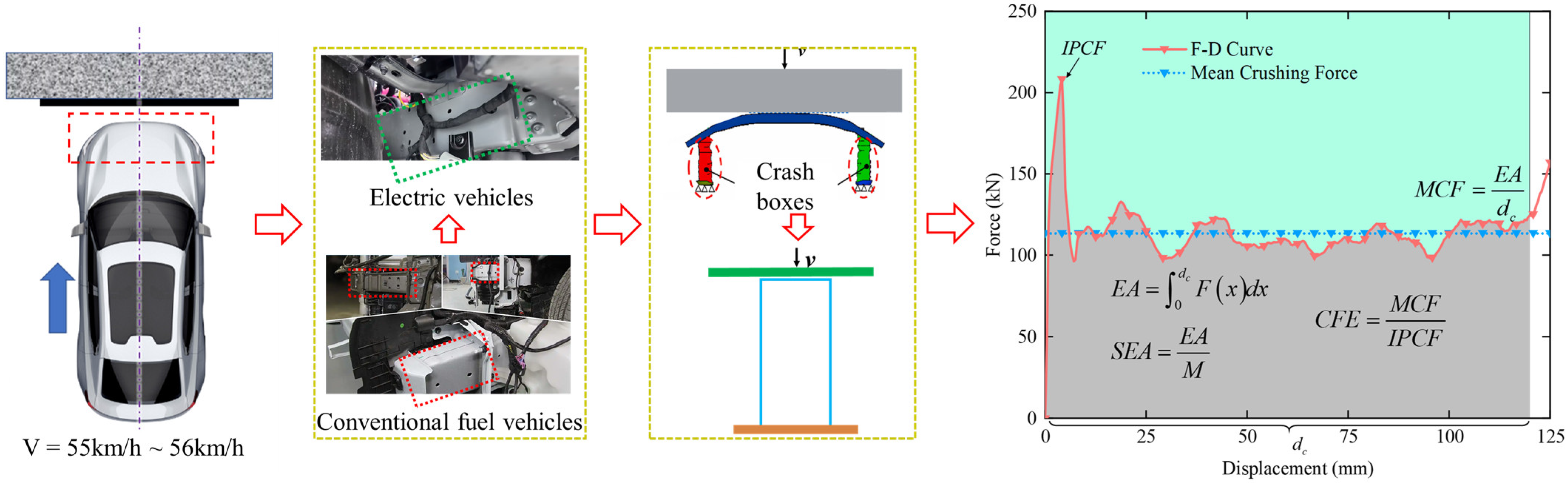
In engineering applications, frontal collisions were identified as prevalent real-world accident scenarios, as shown in Figure 1. A frontal collision could be simplified as an axial compression process of thin-walled structures, where energy was absorbed through the progressive crushing of structural components. Typically, when a thin-walled structure was subjected to axial compression, it exhibited a force–displacement (F-D) pattern similar to that shown in Figure 1, with a distinct maximum peak observed in the initial segment of the curve. The crushing force corresponding to this peak was defined as the IPCF, and strict control of the IPCF within a reasonable range was essential, as an excessively high IPCF could cause instantaneous fatal injury to vehicle occupants.
Another key indicator for evaluating the energy-absorption efficiency of thin-walled structures was the SEA, which could be expressed as follows:
S E A = E A M ,
where M and EA denote the total mass and the total energy absorption of the hybrid tube, respectively. The total energy absorption EA was equivalent to the area under the force–displacement curve, which could be expressed as follows:
E A = 0 d c F x d x ,
where the cut-off displacement dc for the energy absorption process was determined using the energy efficiency method [45]. Accordingly, the mean crushing force (MCF) during the energy absorption process could be derived as the ratio of the total energy absorption to the cut-off displacement, which was expressed as follows:
M C F = E A d c .
The force–displacement curve provided a complete record of the evolution of the crushing force throughout the collision process, including its magnitude, duration, and energy absorption stages, and thus served as a direct basis for analyzing the dynamic structural response. The shape of the curve was found to reflect the efficiency and stability of energy absorption, with fluctuations in the curve typically corresponding to physical events such as plastic deformation and folding formation. An ideal structural design was aimed at achieving an extended stable plateau force, which was indicative of a controlled and progressive crushing process. Therefore, the crush force efficiency (CFE), defined as the ratio of the mean crushing force to the IPCF, was used to reflect the structural load efficiency, which could be expressed as follows:
C F E = M C F I P C F .

2.2. Establishment of Finite Element Model

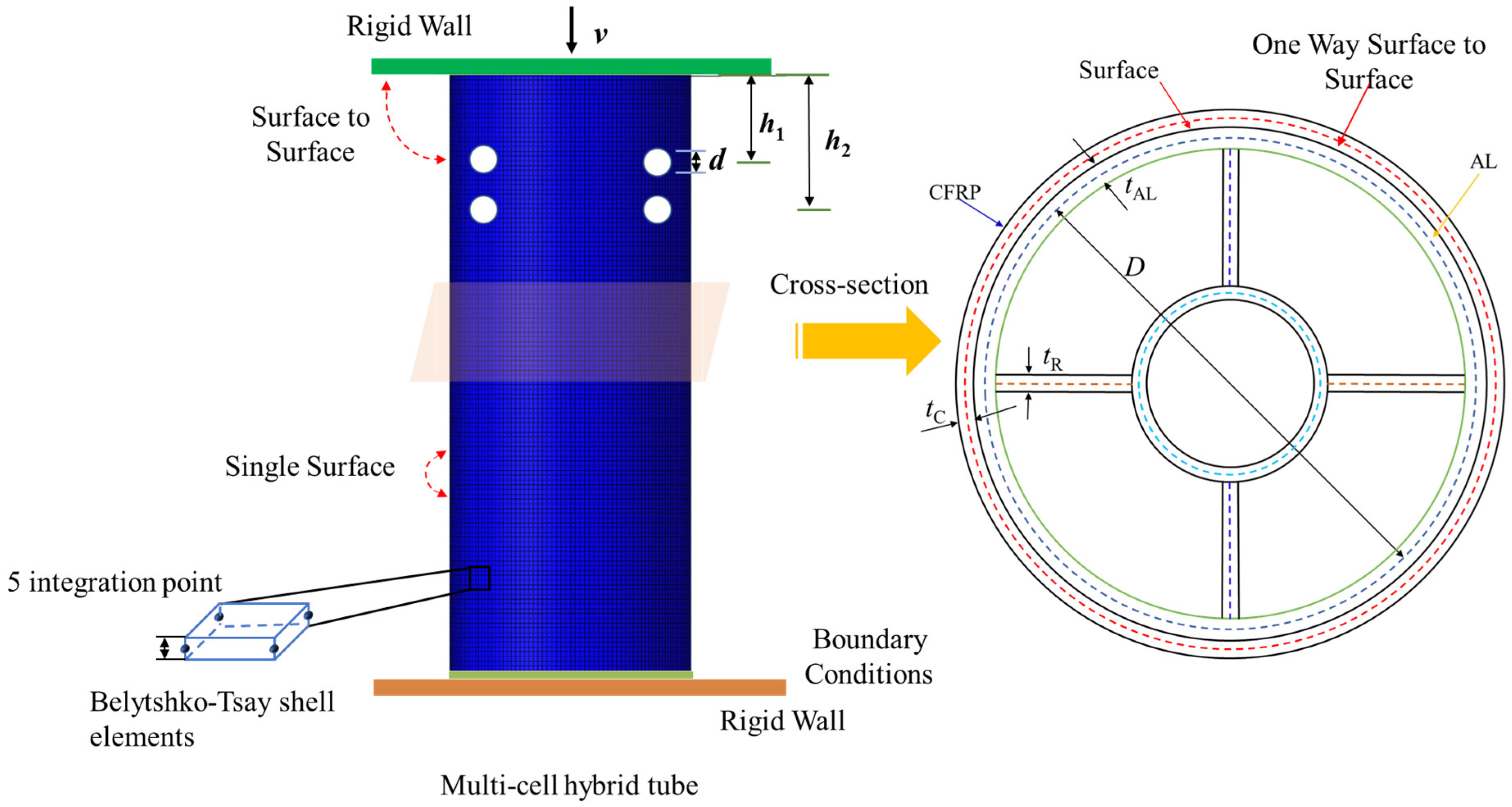
A numerical simulation model was developed using the nonlinear explicit finite element code LS-DYNA to investigate the deformation behavior of CFRP/Al hybrid multi-cell tubes under quasi-static axial compression, as shown in Figure 2. The hybrid tube was constrained against a fixed rigid wall and compressed by a moving rigid wall at a constant velocity v, which simulated a support plate and an impactor, respectively.
The CFRP/Al hybrid multi-cell tubes featured an inner aluminum layer and an outer CFRP structure. The multi-cell cross-section was formed by adding four uniformly distributed radial ribs between two concentric circles. Parametric characterization was implemented using the following parameters: the outer diameter D of the aluminum tube, the diameter ratio τ of the inner and outer aluminum tubes, rib thickness t R , aluminum tube wall thickness t A l , CFRP winding thickness t c , hole diameter d, and distance from the hole center to the top edge h. To ensure spatial uniformity, τ was fixed at 0.5, which balanced the improvement in crashworthiness with the available deformation space. To facilitate performance comparison with existing hybrid tube configurations in Section 4, the CFRP winding angle was set to ±90 degrees based on a comprehensive literature review [5].
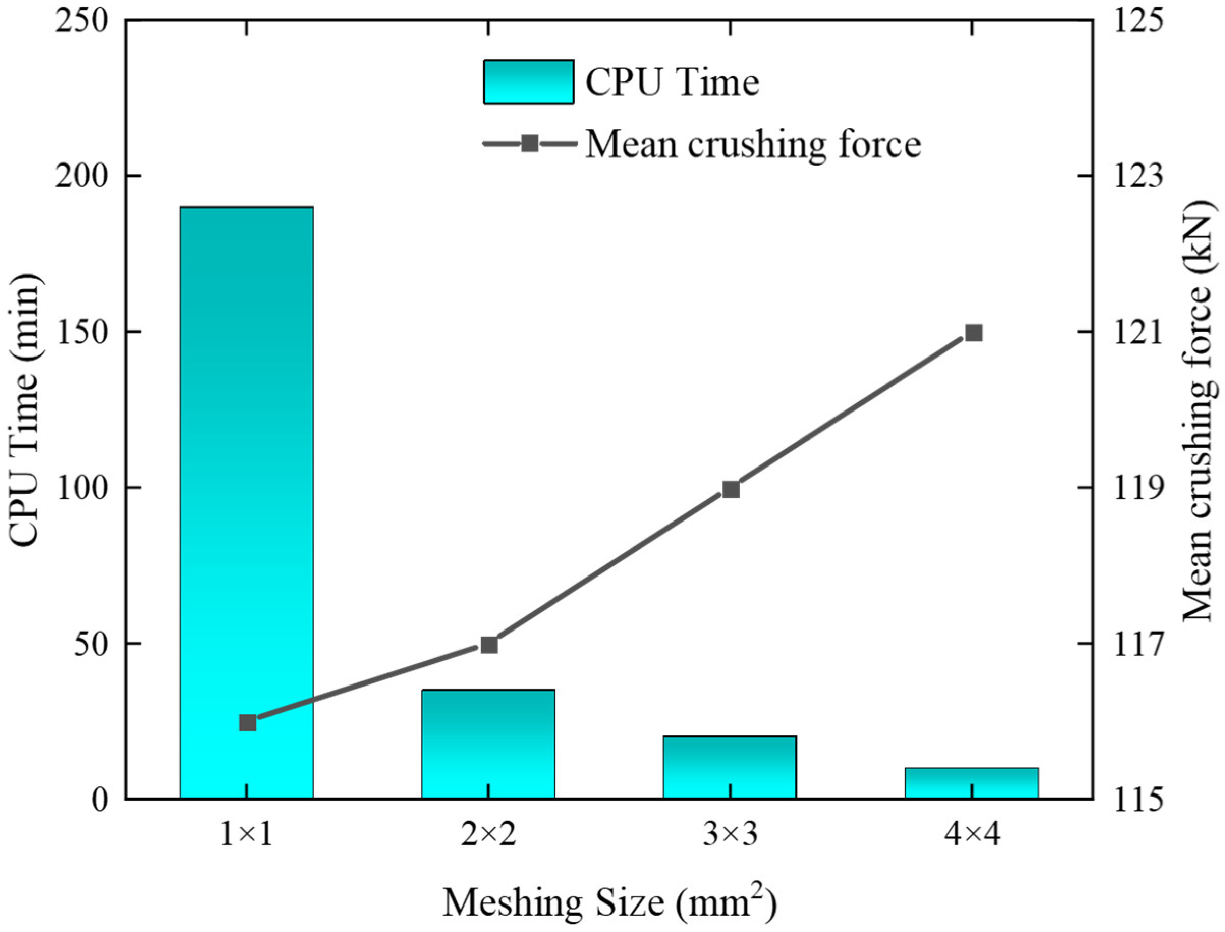
The finite element model was discretized using Belytschko–Tsay shell elements. A mesh sensitivity analysis was conducted to determine the optimal element size, as shown in Figure 3. It was observed that an element size of 2 mm led to a variation of only 0.08% in the MCF compared with an element size of 1 mm, while the computational time increased by nearly four times. Accordingly, 2 mm was selected as the final element size for the model. The aluminum alloy (AA6063-T5) was modeled using the modified Piecewise-Linear-Plasticity material model (Mat 123), with its material properties listed in Table 1 and the true stress–strain curve in Table 2. The CFRP was modeled using the Enhanced-Composite-Damage material model (Mat 54), with the corresponding material parameters provided in Table 3. As the CFRP exhibited stable failure accompanied by the plastic folding deformation of the aluminum alloy, and the CFRP winding angle adopted in this study was 90°, its dominant failure modes included fiber tensile and compressive failure, matrix failure, and intra-laminar shear failure. Therefore, the Chang-Chang failure criterion was adopted to characterize the damage behavior of the composite material. When the triggering holes were small, inter-laminar delamination near these holes was found to exert a negligible effect on the deformation of the overall structure [25]. Considering that the introduction of cohesive elements would substantially increase the number of elements and computational cost, cohesive elements were not employed in this work. The Chang-Chang failure criterion is expressed as follows:
For the case of tensile fiber,
σ 11 X t 2 + β σ 12 S c 2 1 .
For the case of compressive fiber,
σ 11 X c 2 1 .
For the case of tensile matrix,
σ 11 Y t 2 + η σ 12 S c 2 1 .
For the case of compressive matrix,
σ 22 2 S c 2 + Y c 2 S c 2 1 σ 22 2 S c + σ 12 S c 2 1 ,
where σ i j is the stress in i j direction. X c , X t , Y c , Y t , and S c represent the ultimate strengths in longitudinal compression, longitudinal tension, transverse compression, transverse tension, and shear respectively. η is a non-linear coefficient.
Contact-Automatic-One-Way-Surface-To-Surface-Tiebreak was implemented to simulate the interactions between aluminum and CFRP components in the hybrid tube. This algorithm assumed an initial rigid bonding layer between contact pairs, where bond failure was triggered once either normal or shear stresses reached the predefined failure threshold of 10 MPa. Additionally, an automatic surface-to-surface contact algorithm was adopted to model the interactions between the rigid walls and the CFRP/Al hybrid multi-cell tubes. Static and dynamic friction coefficients were consistently defined as 0.3 and 0.2, respectively, across all contact interfaces.

2.3. Validation of the Finite Element Model

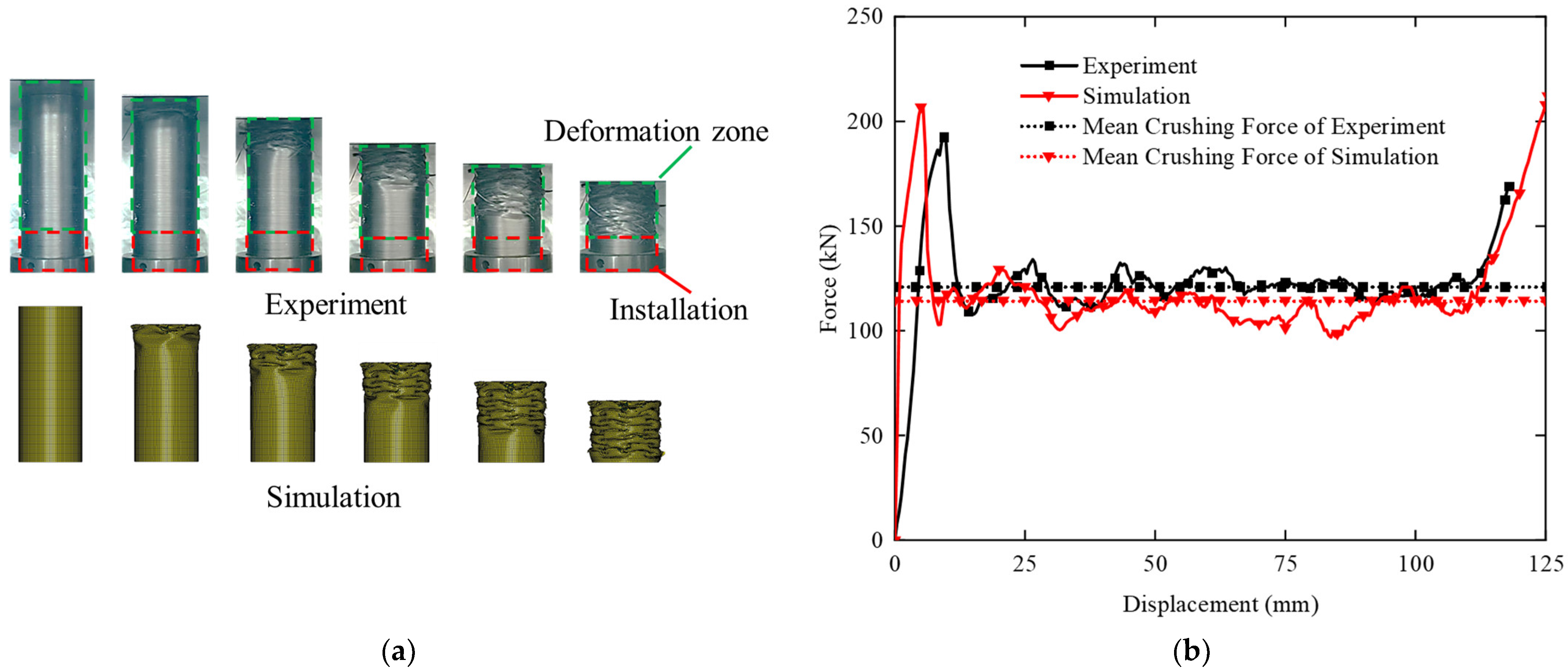
To validate the accuracy of the finite element model developed in this study, the experimental protocol described in a published reference [5] was followed. Axial quasi-static compression simulation was performed as illustrated in Figure 4, with the dimension of the simulation model kept fully consistent with the physical test specimen described in Ref. [5]. The inner core of the hybrid tube consisted of an aluminum tube with a wall thickness of 1.6 mm, an outer diameter of 80 mm, and an inner diameter of 40 mm. Carbon fiber-reinforced polymer was wound onto the multi-cell aluminum tube at a 90° winding angle with a thickness of 1.4 mm. A constant compression speed of 5 mm/min was applied in the simulation, and the force–displacement curve was recorded via a data acquisition system. A comparative analysis was conducted between the numerical prediction obtained from the present FEM and the experimentally observed deformation modes and energy-absorption characteristics reported in Ref. [5].
As shown in Figure 4, a strong correlation was observed between the experimental and simulated deformation modes as well as the reaction force–displacement curves under axial compression. The force–displacement curves from both experiment and simulation comprised three main stages. Under axial compression, the first stage appeared as a linear ascending region accompanied by a high IPCF, which was attributable to the coupling effect between the CFRP and the aluminum core. The experimental specimen exhibited, however, a lower slope in the linear stage and a reduced IPCF compared to the simulation result, which could be ascribed to manufacturing imperfections such as CFRP delamination during the fabrication of the hybrid tube. The second stage corresponded to a fluctuating plateau region, where the external CFRP exhibited stable failure pattern guided by the progressive folding of the aluminum tube. The third stage represented the densification phase, characterized by a rapid rise in reaction force as the structure underwent compaction.
To quantitatively assess the accuracy of the simulation, three key crashworthiness indicators were extracted: IPCF, MCF, and EA. As summarized in Table 4, the discrepancies between the experimental and numerical results for IPCF, MCF, and EA all remained within 10%. Hence, these findings confirmed the validated precision of the FEM for CFRP/Al hybrid multi-cell tubes (CAMHT), which facilitated the extension of research into additional configurations and provided a research basis for the subsequent establishment of predictive models and generation of the required datasets.

3. Parametric Analysis

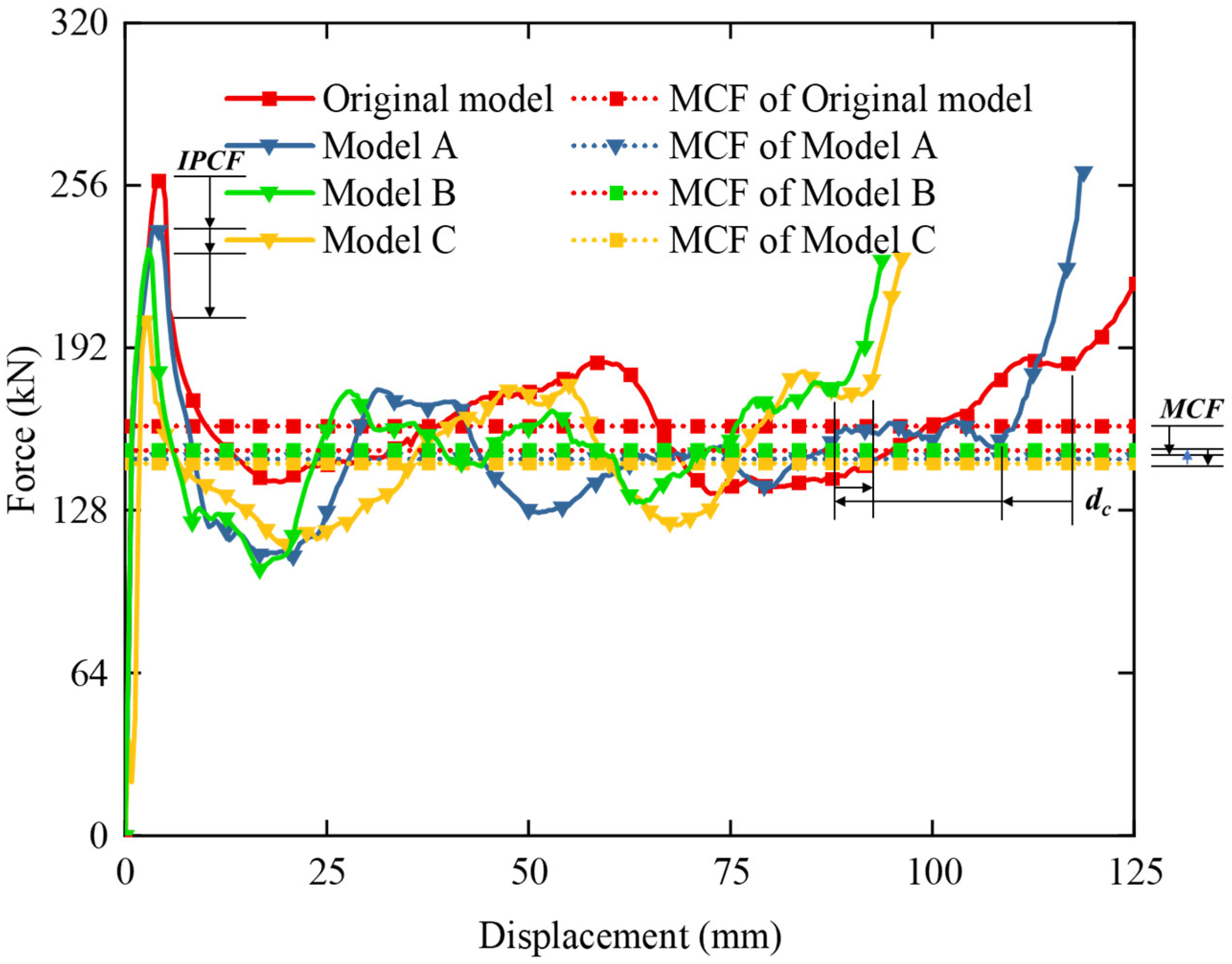
Force–displacement curves of different hybrid tube configurations were compared to elucidate their distinct energy absorption mechanisms, as shown in Figure 5. It was observed that the triggering holes altered the structural stiffness distribution, thereby exerting a significant nonlinear and complex influence on the force–displacement curves, which in turn substantially affected both energy absorption efficiency and load efficiency. The hybrid tube configurations with triggering holes all exhibited a reduction in IPCF, with the reduction becoming more pronounced as the hole size increased. Their MCF was also decreased, though the degree of reduction was not significantly affected by the hole diameter. In contrast, the improvement in CFE was more substantial for configurations with large-diameter triggering holes. In terms of deformation utilization, Model A (d = 4 mm) sustained a prolonged crushing stroke prior to densification, which fully exploited the geometric energy-absorption potential of the structure. Model C (d = 12 mm) underwent, however, premature densification at a significantly reduced displacement, which reflected inefficient collapse and the underutilization of the available deformable space. Consequently, the energy absorption of Model A was substantially greater owing to its higher plateau force and longer effective crushing stroke. These observations underscored that the introduction of small-scale defects could stabilize the post-buckling response and enhance crashworthiness, whereas excessively large openings triggered global buckling and degraded the overall performance of the structure. It was evident that the influence of the triggering holes on load efficiency and energy absorption efficiency was markedly different, which was closely related to their impact on the structural deformation mode. Therefore, a detailed analysis from the perspective of deformation mode was conducted to explain this phenomenon.
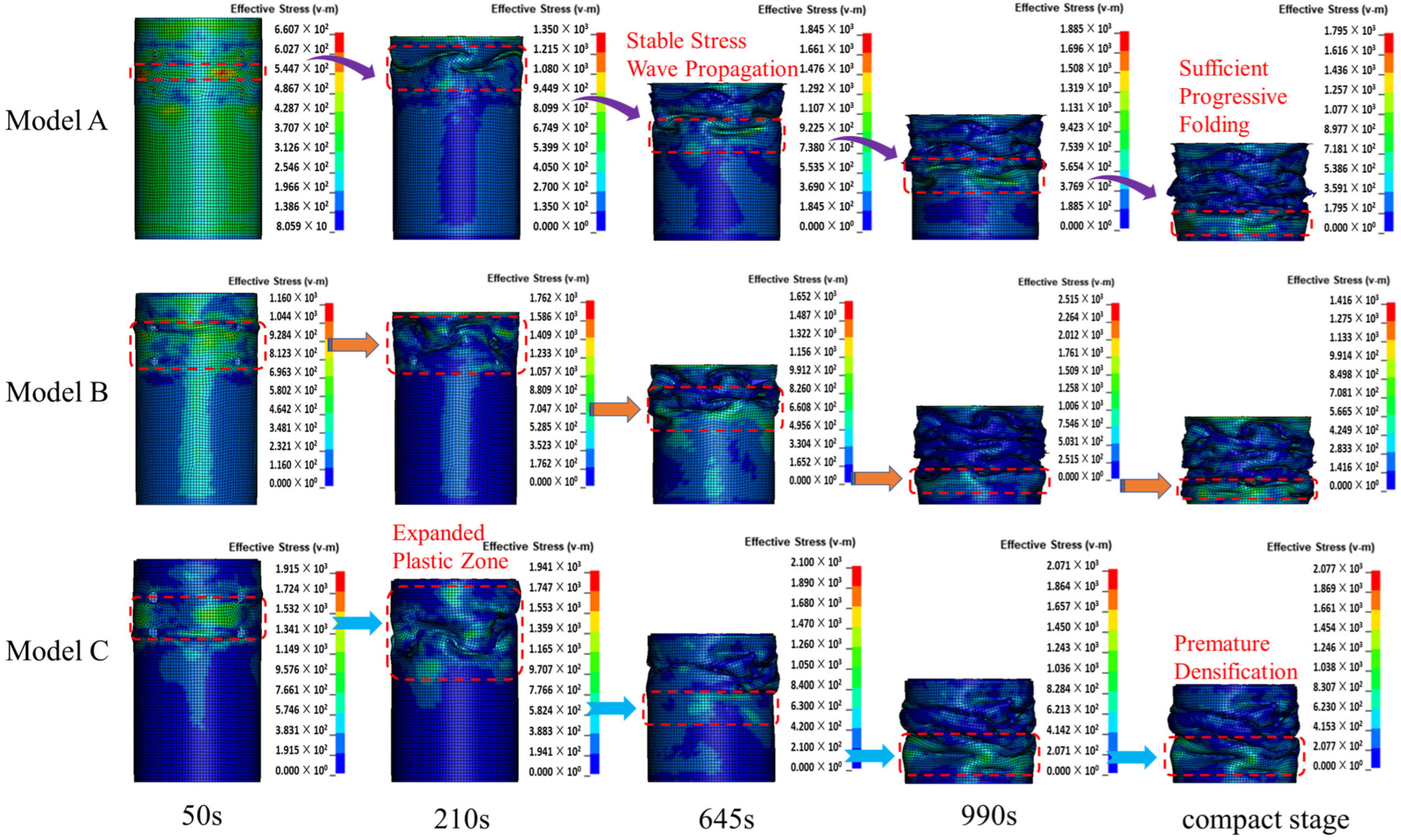
The divergent deformation histories and stress evolution characteristics of the internal aluminum alloy multi-cell tube within the hybrid tube under axial compression, driven by variations in the induced hole diameter, are illustrated in Figure 6. It was observed that even minor dimensional discrepancies in the induced structure triggered distinct failure mechanisms. All three configurations exhibited stress concentrations at the triggering holes. Although a considerable reduction in IPCF and a decrease in structural mass were achieved with larger hole diameters, the continuity of the load-bearing path was severely disrupted, which prevented sufficient plastic deformation from occurring in local regions and consequently led to the premature entry of the structure into the densification stage. This underutilization of the material bearing capacity inevitably compromised the total energy absorption of the structure. In contrast, although only limited reductions in IPCF and mass were achieved with small-diameter trigger holes, the hybrid structure was able to maintain regular and stable folding deformation modes. The above analysis elucidated the aforementioned influence mechanism and also indicated that an optimal induced hole design existed to balance energy absorption efficiency and load efficiency.
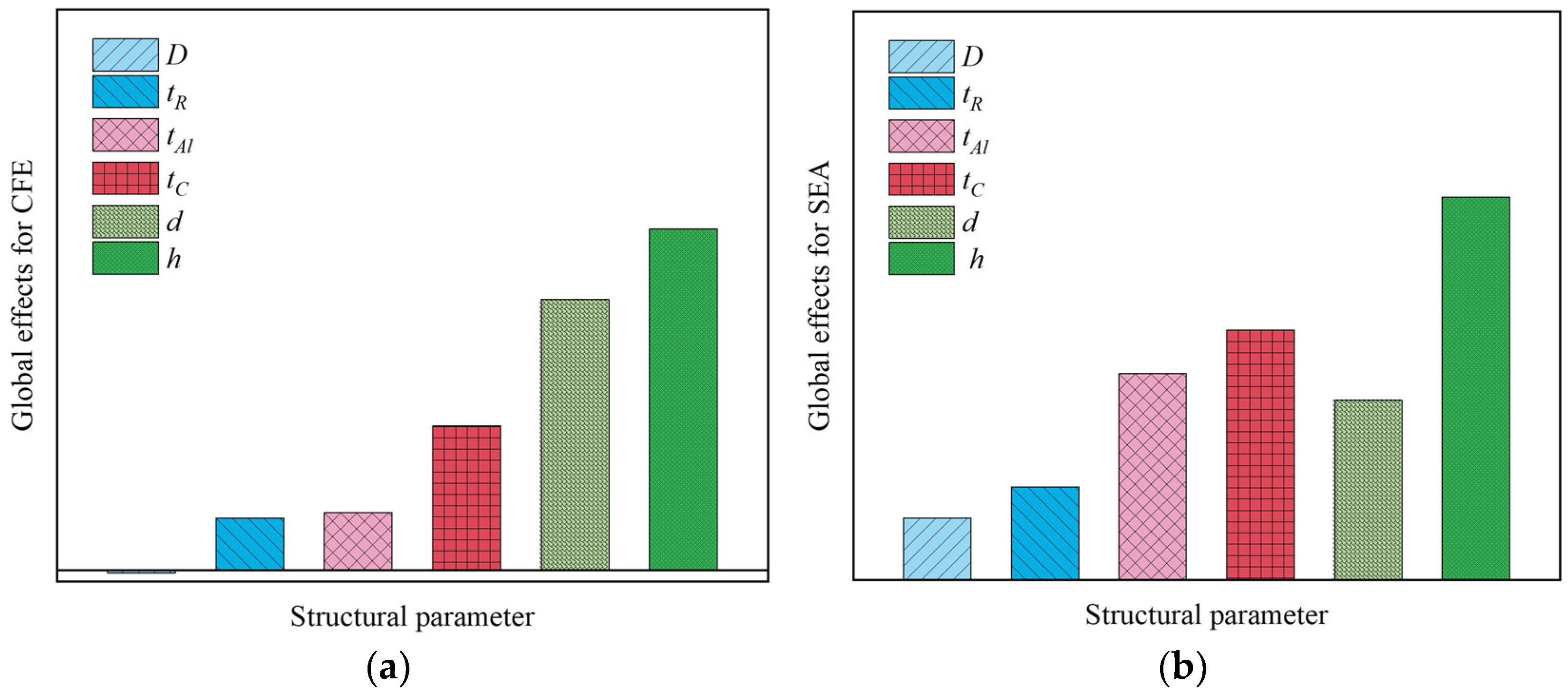
Based on the above mechanism analysis, global sensitivity analysis was performed to identify the configuration parameters that exerted a significant influence on both CFE and SEA, as shown in Figure 7. For CFE, tR, tAl, tC, d, and h were identified as the main controlling parameters, with h exhibiting the most significant influence. The influence levels of tR and tAl were similar, each being approximately 50% of that of tC. Regarding SEA, h was the dominant influencing factor; tAl, tC and d exhibited comparable influence magnitudes, each contributing about half of the effect of h. D and tR showed similar influence levels, each accounting for approximately one-quarter of the effect of h. It was observed that the triggering hole parameters exerted a more significant influence on both CFE and SEA compared to the hybrid tube configuration parameters. The primary reason for this was that the triggering holes not only reduced the IPCF by presetting weak points but also altered the deformation evolution of hybrid tubes. Furthermore, their impact on the coupling effect between CFRP tube and the internal aluminum alloy multi-cell tube was highly nonlinear and difficult to quantify. The introduction of trigger holes increased the dimensionality of the design space while exacerbating the nonlinear influence of structural parameters on performance. Conventional gradient-based methods and many metaheuristic optimizers were found to be prone to convergence to local optima and thus failed to achieve a global trade-off between CFE and SEA.
Furthermore, practical engineering applications often require “performance-to-structure” inverse design. The mapping from the performance space to the parameter space was typically found to be non-unique, and this ill-posed problem was further compounded by the high computational cost of high-fidelity simulations, which severely limited the size of datasets for training reliable inverse models. As a result, traditional population-based algorithms (such as the standard genetic algorithm (GA) and particle swarm optimization (PSO)) used in direct performance-matching workflows were often inefficient, suffering from slow convergence, premature stagnation, and high sensitivity to hyperparameter settings. This rendered precise inverse design computationally prohibitive under practical resource constraints.

4. Intelligent Optimization Design

4.1. Development of a Surrogate Model Based on the Multilayer Perceptron (MLP)

Based on the parameter influence analysis presented in Section 3, traditional static optimization methods proved insufficient to tackle the crashworthiness optimization and inverse design challenges associated with hybrid tubes featuring trigger structures. Consequently, an advanced algorithm possessing “environmental perception” and “strategy self-adaptation” capabilities was required, which motivated the proposal of a reinforcement learning (RL)-guided swarm intelligence optimization framework. By leveraging the dynamic decision-making functionality of Q-Learning to modulate the search behavior of particle swarm optimization (PSO) in real time, this hybrid strategy aimed to guarantee high predictive accuracy while efficiently solving the aforementioned optimization and inverse design problems. Furthermore, a generalized parameter—the total rib length (LSUM)—was introduced to create a universal characterization scheme for multi-cell tubes, effectively enhancing the model’s generalizability and transferability across various cross-sectional geometries.
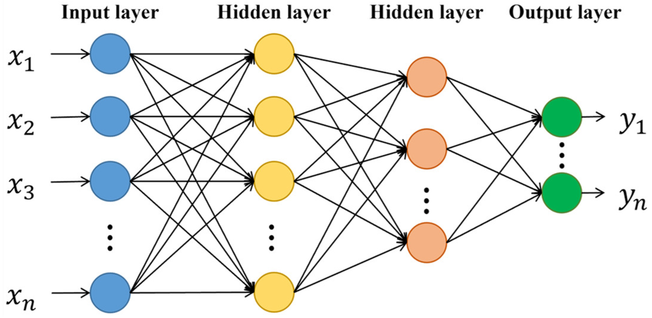
To construct the forward mapping relationship between structural parameters and performance responses, surrogate models were established where structural parameters acted as input variables and performance metrics (SEA and CFE) served as output variables. The initial values and allowable variation ranges for these structural parameters were defined in Table 5. Using the optimal Latin hypercube sampling method, 200 sample points were collected across the eight design variables. An additional 20 sample points were independently chosen within the design space to verify the surrogate model’s fitting accuracy. As shown in Figure 8, a multilayer perceptron (MLP) [46] was employed to develop this surrogate model, leveraging its ability to efficiently learn complex nonlinear relationships while maintaining a flexible architecture. Specifically, 80% of the data was randomly allocated to train the model, with the remaining 20% reserved for testing. The designated MLP consisted of three hidden layers with a structure of (512, 256, 128), applied the ReLU activation function, and was trained using a learning rate of 0.001.
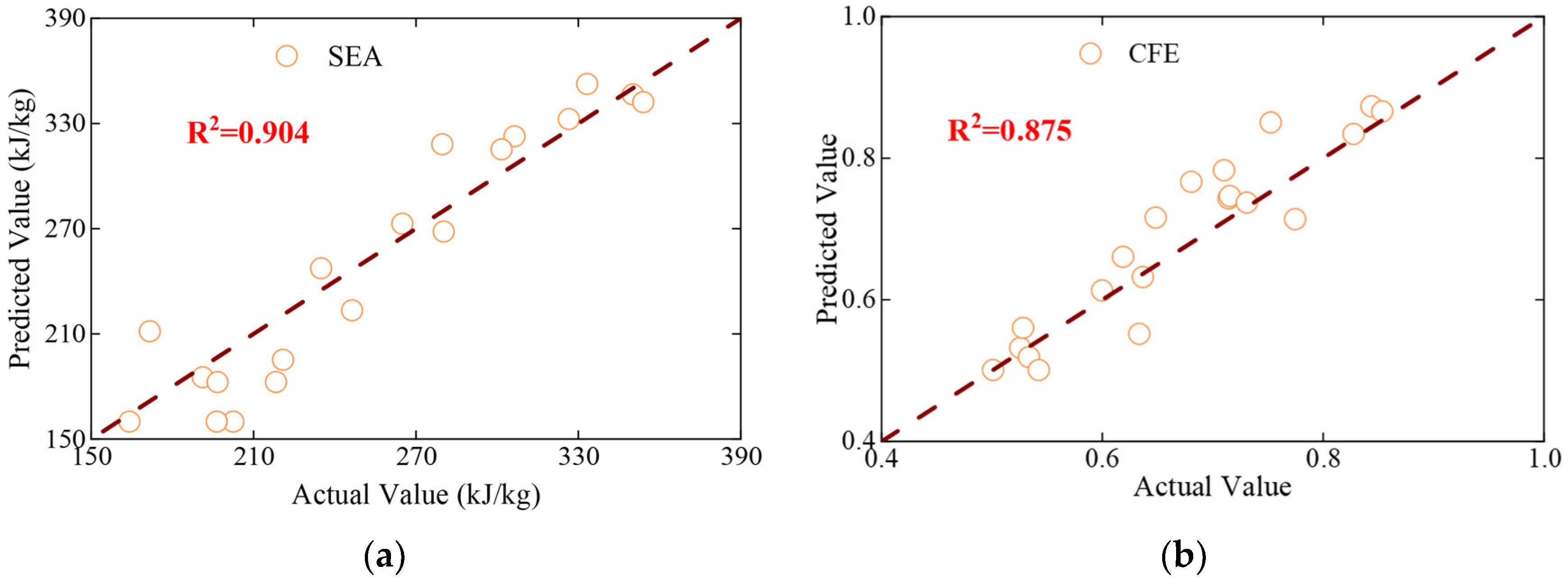
To assess the accuracy of the surrogate model, the coefficient of determination (R2) was calculated for the test set predictions. As shown in Figure 9, the R2 values associated with predicting SEA and CFE from the hybrid tube’s geometric parameters were approximately 0.90, indicating that the developed surrogate model achieved a highly accurate fit.

4.2. Optimization of Swarm Intelligence Algorithms Enhanced by Reinforcement Learning

4.2.1. Inverse Design Principle and QL-PSO Enhancement Algorithm

The inverse mapping process necessitated the construction of an optimization model. Using the known forward mapping relationship between the decision variables X = ( x 1 , x 2 , , x M ) and the objective function f X = ( f 1 X ,   f 2 X , ,   f N X ) , a desired target value f a = ( f 1 a ,   f 2 a , ,   f N a ) was established. An appropriate optimization algorithm was then applied to continuously approximate the predicted objective function f X to the desired target f a .
To facilitate the solution process, this multi-objective inverse design problem was converted into a single-objective optimization task. The primary goal was set to minimize the sum of the relative errors between each predicted value and its corresponding desired value. With the relative error defined as F R E i = | f i X f i ( a ) | f i ( a ) , the objective function was given by:
m i n ( ( F R E 1 , F R E 2 , , F R E N   ) ) .
(1)
Q-Learning (QL)
Q-Learning [47] serves as a model-free reinforcement learning algorithm designed to find an optimal policy. It achieves this by learning a state-action value function, Q s , a , with the ultimate goal of maximizing the agent’s long-term cumulative reward in the environment. Based on the principles of the Bellman equation, the algorithm iteratively updated the estimated value of Q s , a to steadily approximate the optimal Q-function, Q s , a .
Typically, a Q-table was utilized to store the Q-values associated with different state-action pairs. This Q-table was updated at each time step via the following equation:
Q s t , a t Q s t , a t + α [ r t + γ max a Q s t + 1 , a Q s t , a t ] ,
where Q s t , a t represents the Q-value for taking action a t in the current state s t , α stands for the learning rate, r t is the immediate reward received after the action, and γ is the discount factor. Additionally, max a Q s t + 1 , a denotes the maximum Q-value achievable in the next state s t + 1 , effectively capturing the future benefit of making an optimal decision.
During the learning phase, the agent continuously interacted with the environment to update the entries in the Q-table. Once the Q-table reached convergence, it contained the definitive optimal Q-values for all possible actions in every state. At this stage, the optimal policy could be directly derived from the Q-table using the formula below:
π s = arg max a Q s , a .
(2)
Particle swarm optimization algorithm
Particle Swarm Optimization (PSO) serves as a stochastic optimization algorithm rooted in swarm intelligence, drawing inspiration from the collective social behaviors of bird flocks or fish schools. It searches for optimal solutions by mimicking the collaboration and information exchange among individuals within a given solution space. Within the PSO framework, every potential solution is treated as a “particle” navigating this space. By monitoring its personal best position (pbest) alongside the global best position (gbest) discovered by the entire swarm, each particle dynamically adjusts its velocity and spatial coordinates to gradually converge upon the global optimum.
Consider a D-dimensional search space populated by a swarm of N particles. For the i-th particle ( i = 1 , 2 , , N ) , its attributes are characterized by a position vector x i = ( x i 1 , x i 2 , , x i D ) , a velocity vector v i = ( v i 1 , v i 2 , , v i D ) , a personal historical best position p i = ( p i 1 , p i 2 , , p i D ) , and a global historical best position g = ( g 1 ,   g 2 , ,   g D ) .
At each iteration step, the particles’ velocities and positions were updated according to the equations below:
v i d t + 1 = w · v i d t + c 1 r 1 p i d x i d t + c 2 r 2 g d x i d t ,
x i d t + 1 = x i d t + v i d t + 1 ,
where t represents the iteration number, w is the inertia weight, c 1 and c 2 are the cognitive and social coefficients respectively, r 1 and r 2 are random numbers within [0, 1], and d = 1 , 2 , , D .
At the onset of the initialization process, the positions and velocities for all N particles were randomly assigned. Following the evaluation of each particle’s fitness value, the personal best (pbest) and global best (gbest) positions were initially established. In accordance with Equations (12) and (13), the velocity and position of each particle underwent iterative updates. Upon recalculating the fitness values at these new positions, both the individual personal bests and the swarm’s global best were updated accordingly. The optimization procedure concluded once the maximum number of iterations was exhausted or the fitness value attained the predefined accuracy threshold.
(3)
Q-Learning Enhanced PSO (QL-PSO)
Integrating Q-learning into the PSO framework was intended to strike a dynamic balance between the algorithm’s global and local search capabilities, which ensured its stable convergence and enhanced overall optimization efficiency. By updating the Q-table to track the expected rewards for various actions taken in distinct states, Q-learning was utilized to guide the real-time adjustment of key PSO parameters. The detailed workflow of the QL-PSO algorithm is outlined in Algorithm 1.
The state vector s captured the real-time search condition of the current PSO algorithm and was formulated as:
s = [ e t 1 , w , c 1 , c 2 , N P ] ,
where e t 1 denotes the optimization error at the (t−1)-th iteration ( e t = | f g b e s t x T | ).
The action a acted as the decision output from the reinforcement learning model, which included options to decrease ( ) , maintain (0), or increase ( ) the values. These actions corresponded to the tuning of parameters w, c 1 , and c 2 :
a = [ , 0 , ] .
To evaluate the quality of a chosen action a, the reward r was defined as the observed improvement in the relative error. If the optimization performance in the current iteration improved compared to the previous step, a positive reward was granted; otherwise, it was evaluated as negative:
r = e t 1 e t .
Algorithm 1 Q-Learning Enhanced PSO Algorithm
Require: Expected target values x T . Initial inertia weight w. Initial cognitive learning factor c 1 .
Initial social learning factor c 2 . Initial swarm size NP.
1: for number of iterations do
2:   for each individual x i N P  do
3:      Velocity Update:
4:        v i = w · v i + c 1 · r 1 · p b e s t i x i + c 2 · r 2 · ( g b e s t i x i )
5:      Position Update:
6:        x i = x i + v i
7:      Evaluate:
8:       Compute objective function value f ( x i )
9:      Update Personal Best:
10:      if f x i < f ( p b e s t i ) , then p b e s t i x i
11:   end for
12:   Update Global Best:
13:       g b e s t arg m i n i 1 , , N f ( p b e s t i )
14:   Update Q-Learning parameters:
11:    State: s t a t e [ e t 1 , w , c 1 , c 2 , N P ]
12:    Action: Use Q-Learning to select actions [ , 0 , ] .
13:    Update parameters.
14:    Reward:  r = e t 1 e t .
15:    Update Q table with equation (1) and update exploration rate.
16: end for

4.2.2. Testing and Verification of QL-PSO

To verify the optimization capabilities of the improved QL-PSO algorithm within inverse mapping scenarios, three standard high-dimensional multi-objective test functions [48] and their corresponding target objective values were chosen. As summarized in Table 6, these specific functions served to systematically evaluate both the accuracy and efficiency of the enhanced algorithm when handling decision variables of different dimensions.
Across all optimization problems, the primary objective was defined as minimizing the sum of relative errors compared to the target function values, without imposing any additional constraints. For the purpose of comparative analysis, Differential Evolution (DE), Particle Swarm Optimization (PSO), Genetic Algorithm (GA), and Covariance Matrix Adaptation Evolution Strategy (CMA) were selected as the benchmark algorithms. For consistency, the initial population size for all algorithms was uniformly set to 100, with the PSO algorithm specifically utilizing an inertia weight of 0.5. Additionally, the mutation probability for both the DE and GA was set to 0.5, and the initial step size for the CMA algorithm was defined as 0.2. The maximum number of iterations across all algorithms was capped at 200.
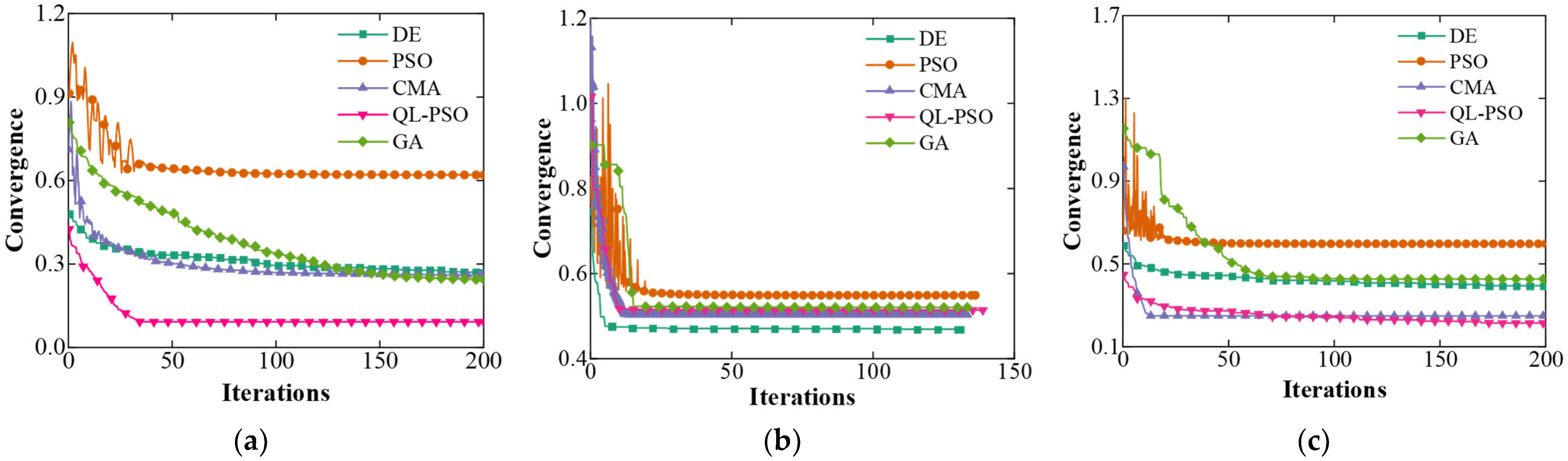
The iterative convergence curves for each algorithm, specifically for the case with 250 decision variables, are presented in Figure 10. Notably, the QL-PSO algorithm consistently delivered excellent performance across all test functions, showcasing both rapid convergence and high accuracy. It outperformed the other optimization algorithms on various complex test functions, which confirmed the effectiveness of integrating Q-learning with swarm intelligence. By utilizing Q-learning to dynamically adjust the PSO parameters, the QL-PSO algorithm successfully improved both the convergence speed and the global search capacity of the standard PSO approach.
Table 7 presented the optimization accuracy and efficiency for each algorithm across the nine test instances, highlighting the best performance in each row. In terms of efficiency, QL-PSO and PSO demonstrated higher computational speed in most test cases. When evaluating optimization accuracy, QL-PSO secured the best results in several instances. As the dimensionality of the decision variables grew, QL-PSO consistently maintained high convergence accuracy, while the performance of the other benchmark algorithms showed a significant decline. This success was largely because the QL-PSO algorithm adaptively chose the most suitable search strategies according to the current optimization state, effectively avoiding premature convergence and escaping local optima.
The primary reason for the significant improvements in the optimization accuracy and efficiency of QL-PSO was its ability to dynamically and adaptively adjust the PSO parameters. This flexibility allowed for a smarter selection of search paths and a better distribution of computational resources, ultimately achieving a well-balanced trade-off between global exploration and local exploitation. Thanks to the incorporation of a reinforcement learning mechanism, the QL-PSO algorithm was able to react more swiftly to state changes during the optimization process. This successfully eliminated the over-reliance on fixed parameters and further boosted the overall performance.
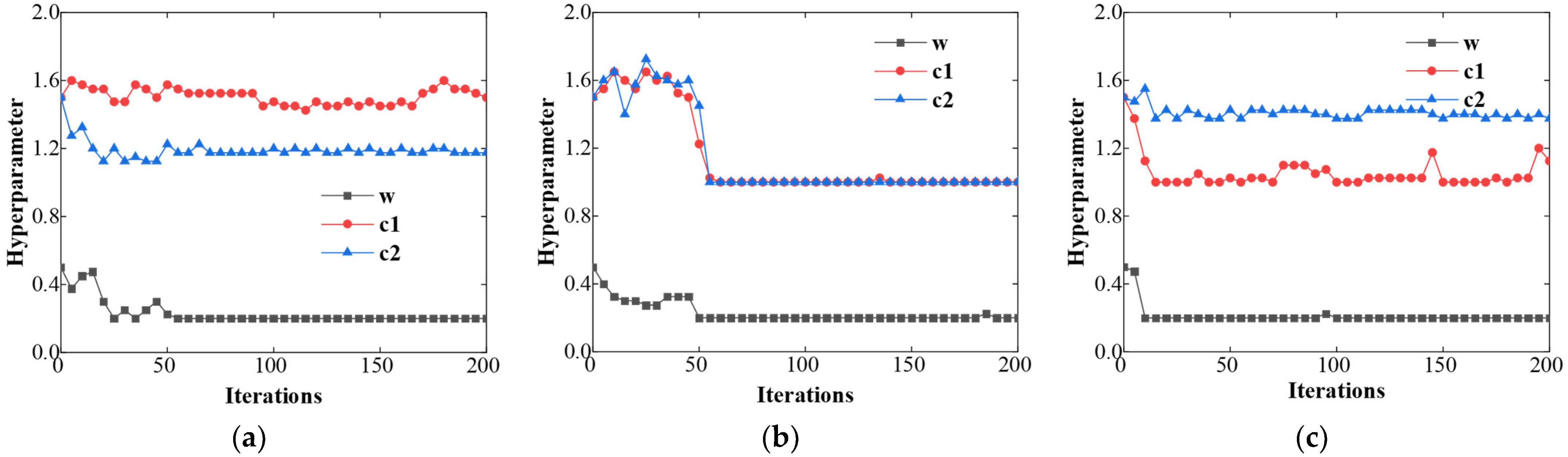
To further verify how effectively the QL mechanism enhances evolutionary algorithms, Figure 11 displayed the dynamic adjustment process of the PSO control parameters ( w , c 1 , c 2 ) using a 50-dimensional problem as a case study. The results showed that under different objective functions, the QL mechanism adaptively fine-tuned the parameters based on the real-time search state, applying distinct control strategies for each unique scenario. In the early and middle stages of the optimization, the parameters showed significant fluctuations, which reflected a strong tendency toward exploration. In the final stages, however, the parameters gradually decayed, thereby lowering the algorithm’s exploration rate. This mode of parameter adjustment kept the algorithm from wandering away from promising regions due to excessive random movements, paving the way for stable convergence to local optimal solutions. Overall, these patterns further validated the effectiveness of the state-action-reward control loop at the heart of Q-learning.
To establish whether the QL-PSO algorithm significantly outperformed the comparative algorithms, the non-parametric Friedman test was applied. This statistical method analyzed the performance rankings of the various algorithms across multiple test cases to determine if meaningful differences existed in their overall performance. Specifically, the null hypothesis (H0) assumed no significant performance differences among all the algorithms, while the alternative hypothesis (H1) suggested that at least two algorithms performed significantly differently. A derived p-value lower than the chosen significance level (α = 0.01) led to the rejection of H0, indicating clear performance variations among the tested algorithms. The steps for conducting the Friedman test were summarized as follows:
(1)
The evaluation metric of the j-th optimization algorithm ( j [ 1 , k ] ) was calculated for the i-th test instance ( i [ 1 , n ] ).
(2)
For each i-th test instance, the algorithms were ranked from best to worst, with a rank value r i j assigned to each algorithm from 1 to k.
(3)
For the j-th algorithm, the average rank across all n test instances was computed as: R j = 1 n i j r i j .
(4)
The Friedman statistic F f was calculated as: F f = 12 n k ( k + 1 ) [ j R j 2 k ( k + 1 ) 2 4 ] .
Table 8 presented the Friedman test results used to examine significant performance variations across the optimization algorithms. For the convergence metric, the test yielded a Friedman statistic of F f = 19.82 , based on degrees of freedom df = k-1 = 4. The benchmark critical value from the chi-square distribution table was χ 0.01 , 4 2 = 13.28 . Given that the calculated F f was significantly higher than 13.28 and the associated p-value was strictly less than 0.01, the null hypothesis (H0) was rejected. This indicated clear, significant differences in how the algorithms converged. Following the same logic, significant differences were also observed regarding the optimization efficiency metric. Therefore, the findings conclusively demonstrated that the QL-PSO algorithm delivered the best convergence performance and optimization efficiency among the tested methods.

4.2.3. Optimization Effect Verification

To verify the crashworthiness improvements achieved by the proposed method relative to existing configurations, a forward multi-objective optimization approach was initially implemented. Specific energy absorption (SEA) and crush force efficiency (CFE) served as the primary performance metrics for the hybrid tube, where maximized values indicated superior energy absorption capabilities. Consequently, the objective function for this forward optimization was formulated to maximize both indicators, employing the QL-MOPSO algorithm:
f i n d   D V = [ D V 1 , D V 2 , , D V 8 ] max S E A   &   m a x ( C F E ) .
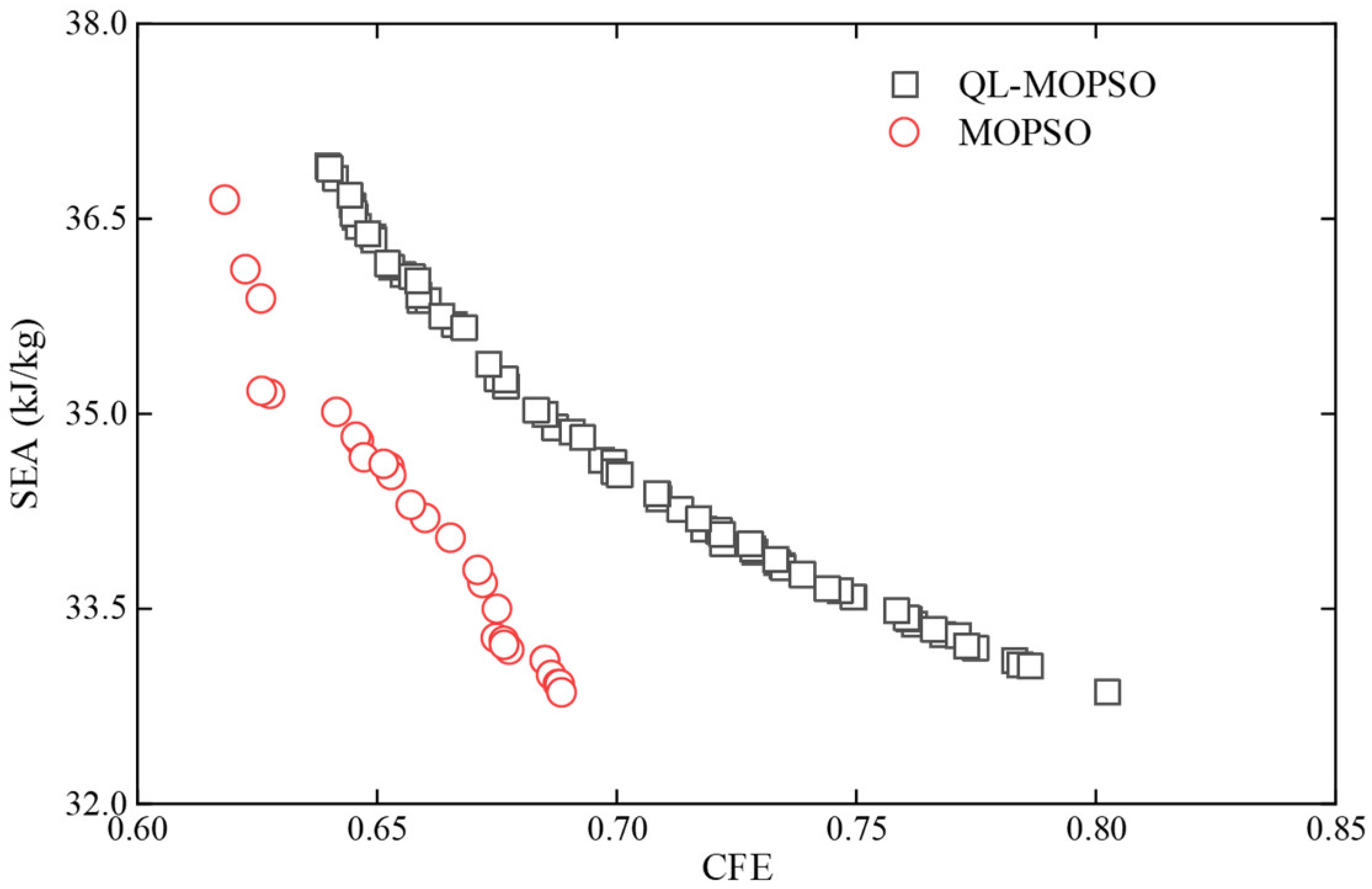
Figure 12 depicted the Pareto front generated by the multi-objective optimization. Due to the mutually non-dominated nature of these solutions, a single optimal configuration could not be directly isolated from the solution set. To resolve this, the Technique for Order of Preference by Similarity to Ideal Solution (TOPSIS)—a multi-criteria decision-making framework—was applied. The principal advantage of TOPSIS lay in its capacity to systematically assess each alternative’s overall performance by computing its relative proximity to both positive and negative ideal reference points. The optimal design ultimately identified via TOPSIS corresponded to the 17th parameter set, yielding objective values of SEA = 34.5 kJ/kg and CFE = 0.71. The comprehensive optimization parameters were detailed in Table 9, with the optimization process requiring a computational time of 8.64 s. In contrast, the standard MOPSO algorithm produced optimal results of SEA = 33.5 kJ/kg and CFE = 0.67, consuming 11.07 s. These results demonstrated that the QL-MOPSO algorithm not only enhanced computational efficiency by 22% compared to the baseline MOPSO but also simultaneously achieved superior optimization outcomes.
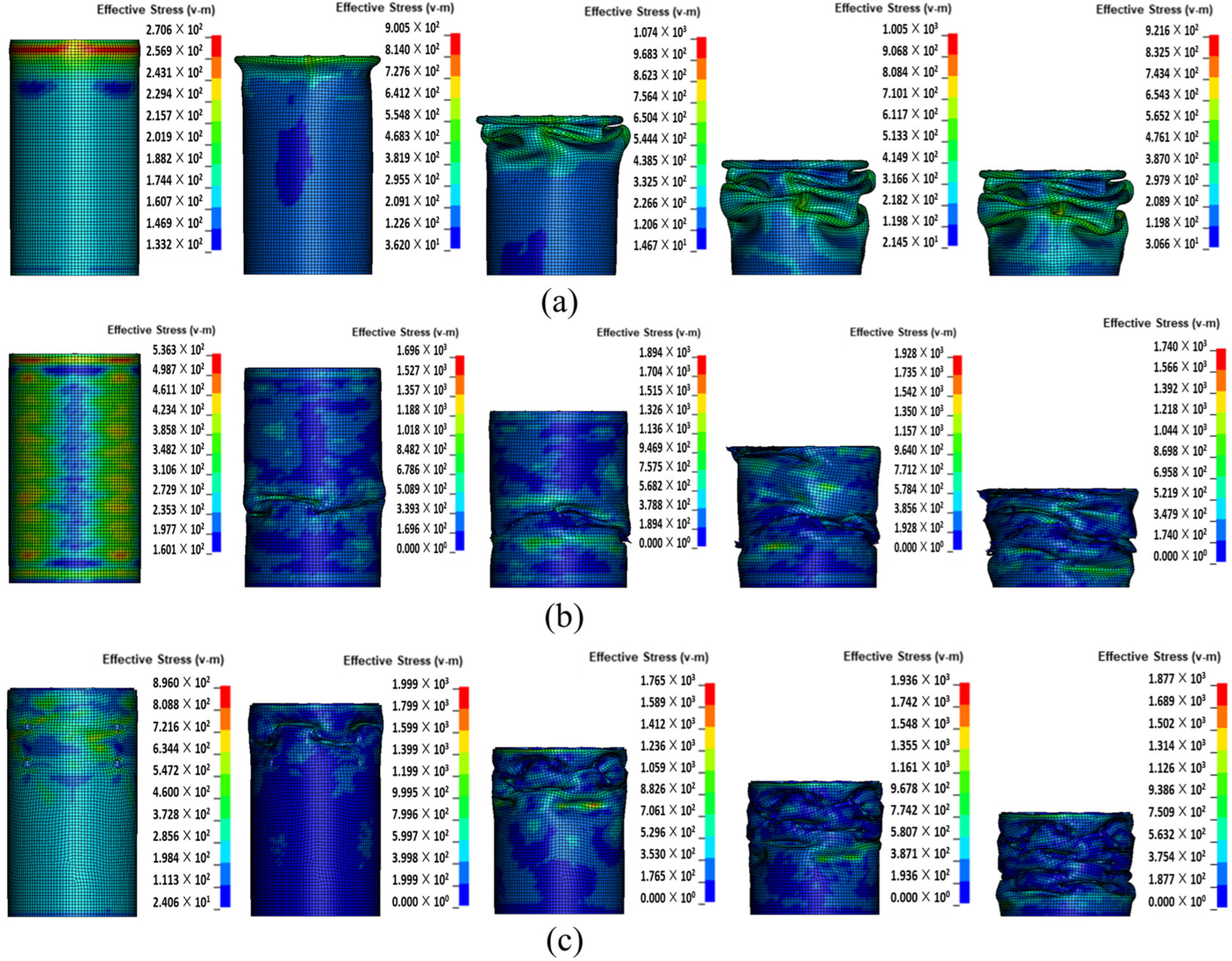
Table 10 presented the SEA and CFE results for the pure aluminum tube, the standard hybrid tube without trigger holes, and the optimized hybrid tube featuring trigger holes under axial compression loading conditions. When evaluated alongside the deformation modes shown in Figure 13, it became evident that the external CFRP layer provided significant circumferential confinement to the inner aluminum tube. This confinement successfully resisted outward expansion, which in turn steadily increased the overall mean crushing force. At the same time, the synergistic interaction between the two materials resulted in a marked improvement in the SEA. Nevertheless, lacking a trigger structure to guide the structural collapse, this synergistic effect was somewhat offset by unstable local buckling, limiting the maximum achievable SEA. In contrast, the optimized hybrid tube benefited from the predefined trigger holes, which induced a more thorough and controlled deformation process. As a result, it secured a notable increase in SEA without sacrificing load efficiency, keeping the CFE at an essentially constant level.
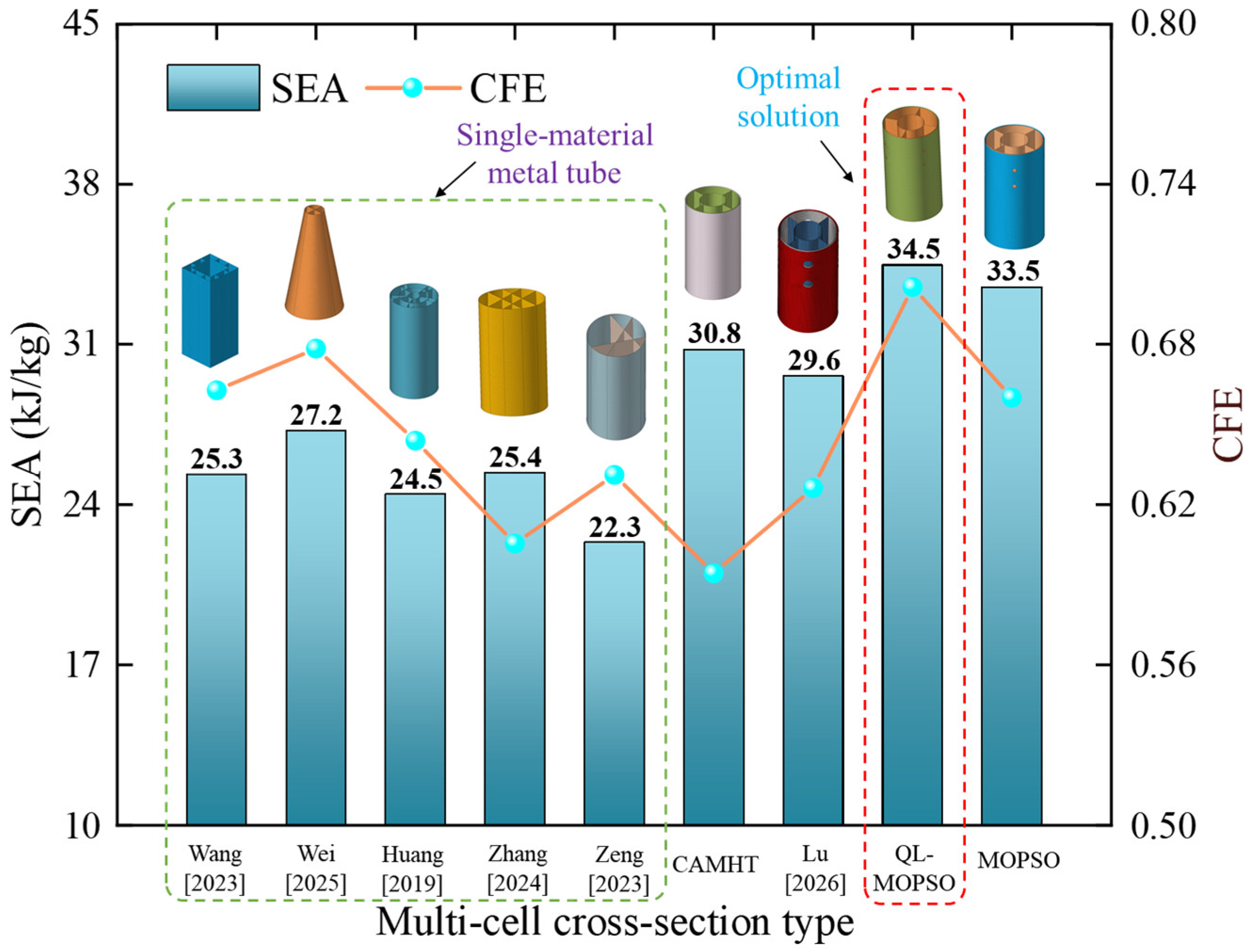
Figure 14 displayed how different structural configurations were distributed across the performance space defined by SEA and CFE. This distribution highlighted a clear evolutionary pattern in energy absorption performance, progressing from basic material enhancement and structural induction to advanced intelligent optimization. Initially, material enhancement showed a double-edged effect. When compared to the pure aluminum tube, the standard, unperforated CFRP/Al hybrid tube delivered a major improvement in SEA, driven by the synergistic coupling between the CFRP layer and the aluminum alloy. Nevertheless, this benefit came with a clear trade-off: adding CFRP drastically increased the initial structural stiffness. Consequently, the IPCF surged much faster than the MCF, leading to a severe drop in CFE that fell below even that of the pure metal tube. This created a scenario characterized by “high energy absorption efficiency yet low load efficiency”. Next, the introduction of the trigger hole design successfully lowered the IPCF by creating local areas of weakened stiffness, which allowed the CFE to partially recover compared to the unperforated version. While traditional metaheuristic algorithms managed to improve both SEA and CFE during optimization, their tendency to get trapped in local optima limited their effectiveness in such a highly nonlinear design space. In contrast, the QL-PSO algorithm introduced in this study displayed exceptional global search capabilities. By effectively handling the complex, nonlinear relationships between the trigger parameters and performance metrics, the QL-PSO algorithm maximized the structural and material potential of the hybrid tube. Ultimately, the optimized configuration claimed the top spot in the performance space, achieving an SEA of 34.5 kJ/kg and a CFE of 0.71—the highest levels among all the designs compared.
To further evaluate how well the QL-PSO algorithm performs in inverse design optimization, specific performance targets for the hybrid tube were set using the forward optimization results from Table 9 as a baseline. In this scenario, the target SEA was decreased by 10%, and the target CFE was increased by 10% compared to the previously optimized energy absorption values. This resulted in new expected response values of SEA = 31.05 kJ/kg and CFE = 0.77.
Using these expected targets, a mathematical model was built to handle the inverse mapping from the structural geometric parameters to the desired performance responses. The primary goal of this optimization was to minimize the total relative error between the predicted outcomes and the target values for both metrics. The optimization model was defined as follows:
f i n d   D V = [ D V 1 , D V 2 , , D V 8 ] m i n ( S E A S E A 0 S E A 0 + | C F E C F E 0 | C F E 0 ) .
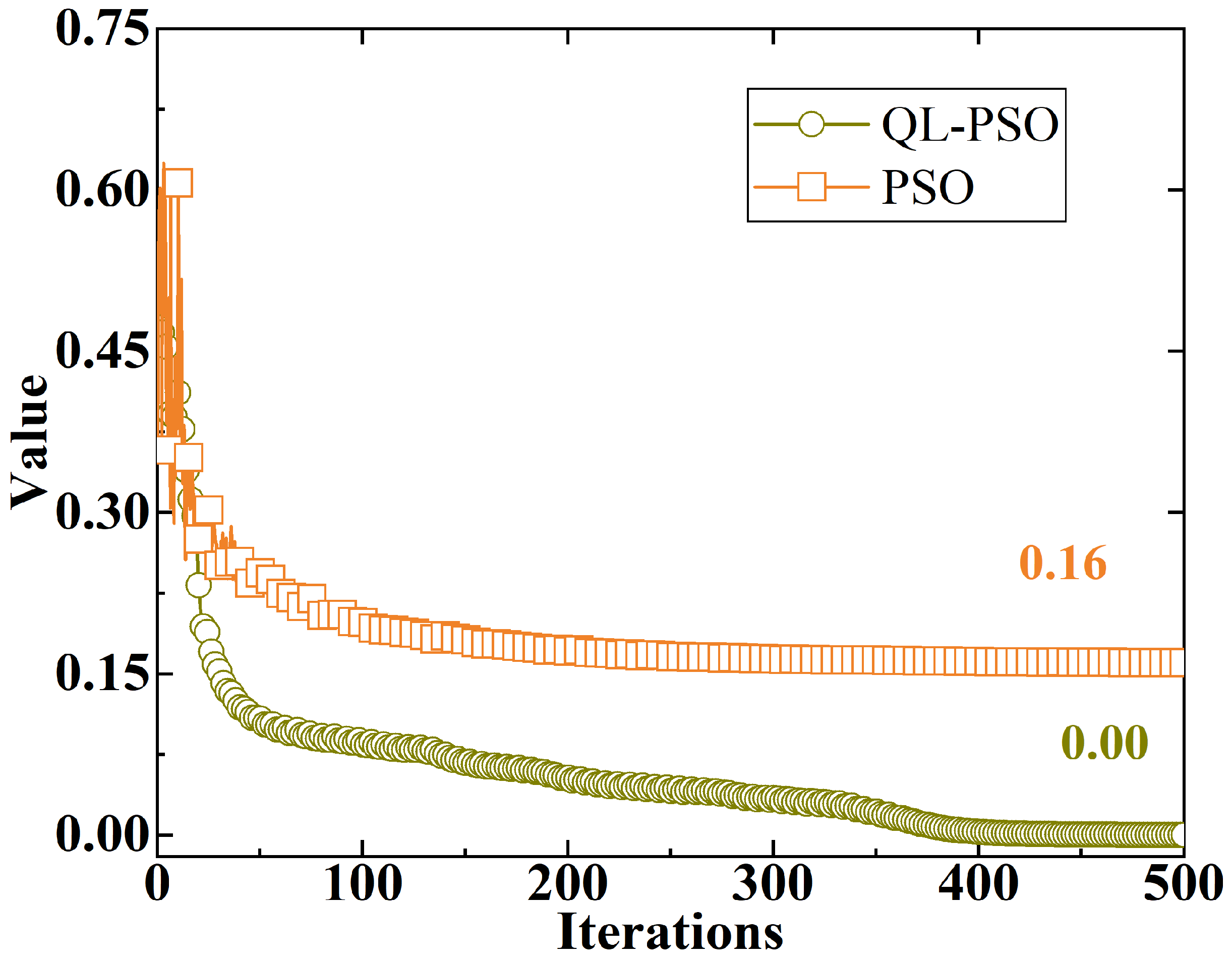
Figure 15 displayed the iteration curves for both the QL-PSO algorithm and the comparative PSO algorithm throughout this process. The curves showed a clear declining trend before leveling off at around 400 iterations. Ultimately, the QL-PSO algorithm successfully reached a relative error sum of exactly 0, while the standard PSO algorithm only managed to converge to an error sum of 0.16. This outcome clearly indicated that the QL-PSO algorithm could perfectly hit the desired design objectives—namely, a 10% drop in SEA coupled with a 10% rise in CFE—under the given constraints. The eight geometric parameters predicted by this inverse design were listed in Table 11. The entire optimization took just 9.429 s of computational time. In contrast, the standard PSO algorithm fell short of the targets (achieving an SEA of 31.2 kJ/kg and a CFE of 0.66 with a 0.16 relative error) and required a longer computational time of 14.52 s. Overall, these results proved that the proposed QL-PSO algorithm achieved favorable convergence in a very short amount of time, confirming its strong practical potential for inverse design optimization.

5. Conclusions

An intelligent optimization design methodology for hybrid tubes with triggering holes was established in this paper to achieve an optimal balance between energy absorption efficiency and crushing force efficiency. The key conclusions are summarized as follows:
  • Triggering holes were introduced to induce preferential deformation of the hybrid tube at weak locations, and a significant reduction in IPCF was achieved. Notably, a prominent nonlinear influence of triggering holes on the coupling effect between CFRP and aluminum alloy was observed: insufficient IPCF reduction was caused by undersized triggering holes, whereas the continuity of load transfer was disrupted and irregular deformation was induced by oversized ones.
  • A dynamic balance between exploration and exploitation was achieved by the proposed QL-PSO algorithm via Q-learning, and common drawbacks of conventional swarm intelligence algorithms were effectively mitigated. Its robust convergence and high computational efficiency were validated by numerical benchmarks—optimization performance and convergence rate were improved by approximately 2-fold and 1.5-fold, respectively, compared to baseline algorithms.
  • When employed in the multi-objective crashworthiness optimization of SEA and CFE for hybrid tubes, the optimal configuration determined in this work demonstrated competitive performance against those reported in existing literature, with corresponding SEA and CFE values of 34.5 kJ/kg and 0.71, respectively.
  • In comparison with traditional optimization algorithms, the proposed QL-PSO algorithm was successfully implemented in inverse design based on target performance requirements, and targeted regulation of structural performance was achieved (SEA = 31.05 kJ/kg and CFE = 0.77). In contrast, the conventional PSO algorithm achieved SEA = 31.2 kJ/kg and CFE = 0.66, with a total relative error of 0.16 relative to the target values. Thus, the effectiveness and reliability of the QL-PSO algorithm in terms of both global search efficiency and inverse mapping accuracy were fully verified.
  • This study has several inherent limitations: the effects of delamination failure induced by stress concentration around triggering holes, as well as manufacturing defects, impact angle, and ambient temperature, on the crashworthiness of hybrid tubes were not considered in the current analysis. These influential factors will be prioritized in future research to further enhance the engineering applicability and practical value of the proposed methodology.

Author Contributions

Conceptualization, Y.M.; methodology, Y.M.; software, Y.M.; validation, H.T. and J.D.; formal analysis, J.W.; investigation, S.W.; resources, Z.H.; data curation, Z.Z.; writing—original draft preparation, Y.M.; writing—review and editing, Z.H.; visualization, Z.W.; project administration, Z.H.; funding acquisition, Z.H. All authors have read and agreed to the published version of the manuscript.

Funding

This research was funded by MAJOR SCIENCE AND TECHNOLOGY SPECIAL PROJECT OF JILIN PROVINCE AND CHANGCHUN CITY, grant number 20240301010ZD.

Data Availability Statement

The data presented in this study are available on request from the corresponding author due to privacy restrictions.

Acknowledgments

The authors would like to thank the editor and the anonymous reviewers for their careful reading and constructive comments, which have greatly improved this work.

Conflicts of Interest

Authors Yan Ma, Zehui Huang, Hongbin Tang, Jianjiao Deng, Jingchun Wang, and Shibin Wang were employed by the FAW Global R&D Center, National key Laboratory of Advanced Vehicle Integration and Control. Authors Zhiguo Zhang and Zhenjiang Wu were employed by the CATARC (Tianjin) Automotive Engineering Research Institute Co., Ltd. The authors declare that the research was conducted in the absence of any commercial or financial relationships that could be construed as a potential conflict of interest.

References

  1. Zhang, J.; Lu, B.; Zheng, D. Experimental and numerical study on energy absorption performance of CFRP/aluminum hybrid square tubes under axial loading. Thin-Walled Struct. 2020, 155, 106948. [Google Scholar] [CrossRef]
  2. Lu, B.; Shen, C.; Zhang, J. Study on energy absorption performance of variable thickness CFRP aluminum hybrid square tubes under axial loading. Compos. Struct. 2021, 276, 114469. [Google Scholar] [CrossRef]
  3. Kong, D.; Wang, D.; Xie, C.; Wang, S.; Zhang, X.; Zhang, Z. Investigation and optimization of structural parameters for the forming quality and mechanical properties of CFRP/Al self-piercing riveting. Int. J. Adv. Manuf. Technol. 2023, 127, 3297–3313. [Google Scholar] [CrossRef]
  4. Liu, B.; Liang, H.; Lu, C.; Wang, D. Oblique compression instability prediction and crashworthiness design for hybrid tube. Int. J. Mech. Sci. 2025, 296, 110292. [Google Scholar] [CrossRef]
  5. Lu, C.; Liang, H.; Wang, D.; Wang, H.; Li, H.; Chen, J. Structural design and crashworthiness prediction of hybrid tubes. Int. J. Mech. Sci. 2026, 310, 111096. [Google Scholar] [CrossRef]
  6. Wang, S.; Ma, Q.; Gan, X.; Zhou, T. Crashworthiness analysis and multi-objective optimization of Al/CFRP tubes with induced holes. Polym. Compos. 2021, 42, 1. [Google Scholar]
  7. Liang, H.; Liu, B.; Pu, Y.; Sun, H.; Wang, D. Crashworthiness analysis of variable thickness CFRP/Al hybrid multi-cell tube. Int. J. Mech. Sci. 2024, 266, 108959. [Google Scholar] [CrossRef]
  8. Zhang, L.; Guo, Y.; Cheng, Z.; Dou, W.; Stichel, S. Integrated topology optimization method for crashworthiness of metal-FRP hybrid thin-walled tubes: A review and analysis. Chin. J. Mech. Eng. 2026, 39, 100046. [Google Scholar] [CrossRef]
  9. Ren, Y.; Jiang, H.; Liu, Z. Evaluation of double-and triple-coupled triggering mechanisms to improve crashworthiness of composite tubes. Int. J. Mech. Sci. 2019, 157, 1–12. [Google Scholar] [CrossRef]
  10. Khan, R.; Mahdi, E. Effect of trigger mechanisms on the quasi-static axial crushing behavior of glass epoxy/polyvinyl chloride hybrid composite tubes. Thin-Walled Struct. 2023, 182, 110306. [Google Scholar] [CrossRef]
  11. Hussein, R.; Ruan, D.; Lu, G. Cutting and crushing of square aluminium/CFRP tubes. Compos. Struct. 2017, 171, 403–418. [Google Scholar] [CrossRef]
  12. Hussein, R.; Ruan, D.; Lu, G. An energy dissipating mechanism for crushing square aluminium/CFRP tubes. Compos. Struct. 2018, 183, 643–653. [Google Scholar] [CrossRef]
  13. Cetin, E.; Baykasoglu, A.; Erdin, M. Experimental investigation of the axial crushing behavior of aluminum/CFRP hybrid tubes with circular-hole triggering mechanism. Thin-Walled Struct. 2023, 182, 110321. [Google Scholar] [CrossRef]
  14. Zhang, Z.; Feng, C.; Zhao, L. Crashworthiness analysis and optimization design of special-shaped thin-walled tubes by experiments and numerical simulation. Thin-Walled Struct. 2024, 205, 112240. [Google Scholar] [CrossRef]
  15. Baky, M.; Allah, M.; Kamel, M. Energy absorption characteristics of E-glass/epoxy over-wrapped aluminum pipes with induced holes: An experimental research. Sci. Rep. 2022, 12, 21097. [Google Scholar] [CrossRef]
  16. Dong, F.; Ma, Q.; Gan, X.; Zhou, T. Crashworthiness analysis of perforated metal/composite thin-walled structures under axial and oblique loading. Polym. Compos. 2021, 42, 2019–2036. [Google Scholar]
  17. Zhang, C.; Sun, Y.; Sosa, J. Numerical simulation and multi-objective optimization of thin-walled aluminum/carbon fiber reinforced plastic hybrid tubes under axial crushing. J. Thermoplast. Compos. Mater. 2024, 37, 3591–3615. [Google Scholar] [CrossRef]
  18. Ma, Q.; Nie, N.; Zhang, S. Comprehensive evaluation of energy absorption characteristics of Al-CFRP hybrid tube under radial impacts. Polym. Compos. 2024, 45, 6059–6076. [Google Scholar] [CrossRef]
  19. Alshahrani, H.; Sebaey, T.; Allah, M. Metal/polymer composite cylinders for crash energy absorption applications. Polym. Compos. 2022, 43, 8771–8783. [Google Scholar] [CrossRef]
  20. Qin, X.; Ma, Q.; Gan, X. Failure analysis and multi-objective optimization of crashworthiness of variable thickness Al-CFRP hybrid tubes under multiple loading conditions. Thin-Walled Struct. 2023, 184, 110452. [Google Scholar] [CrossRef]
  21. Emadi, M.; Beheshti, H.; Rarani, M. Multi-objective optimization of hybrid aluminum–composite tube under axial crushing. Int. J. Appl. Mech. 2020, 12, 2050042. [Google Scholar] [CrossRef]
  22. Kalhor, R.; Akbaeashahi, H.; Case, S. Numerical modeling of the effects of FRP thickness and stacking sequence on energy absorption of metal–FRP square tubes. Compos. Struct. 2016, 147, 231–246. [Google Scholar] [CrossRef]
  23. Ma, Q.; Dong, B.; Zha, Y. Multi-objective optimization for energy absorption of carbon fiber-reinforced plastic/aluminum hybrid circular tube under both transverse and axial loading. J. Mater. Eng. Perform. 2020, 29, 5609–5624. [Google Scholar] [CrossRef]
  24. Yu, H.; Shi, H.; Chen, S. A novel multi-cell CFRP/AA6061 hybrid tube and its structural multiobjective optimization. Compos. Struct. 2019, 209, 579–589. [Google Scholar] [CrossRef]
  25. Zha, Y.; Wang, S.; Ma, Q. Study on the axial impact of Al-CFRP thin-walled tubes with induced design. Polym. Compos. 2022, 43, 4073–4792. [Google Scholar] [CrossRef]
  26. Ma, Q.; Cai, W.; Bai, C. Theoretical analysis and crashworthiness optimization of multi-cell Al-CFRP hybrid tube. J. Reinf. Plast. Comp. 2025, 44, 1645–1665. [Google Scholar] [CrossRef]
  27. Cam, S.; Sofuoglu, H. An investigation on crashworthiness performance of adhesive bonding in automobile hybrid front bumper system subjected to high-speed impact. Int. J. Impact Eng. 2023, 173, 104478. [Google Scholar] [CrossRef]
  28. Wang, D.; Xu, W.; Wang, Y.; Gao, J. Design and optimization of tapered carbon-fiber-reinforced polymer rim for carbon/aluminum assembled wheel. Polym. Compos. 2021, 42, 253–270. [Google Scholar] [CrossRef]
  29. Sun, H.; Burton, H.V.; Huang, H. Machine learning applications for building structural design and performance assessment: State-of-the-art review. J. Build. Eng. 2021, 33, 101816. [Google Scholar] [CrossRef]
  30. Zhou, Q.; Lu, S.; Wu, Y.; Wang, J. Property-Oriented Material Design Based on a Data-Driven Machine Learning Technique. J. Phys. Chem. Lett. 2020, 11, 3920–3927. [Google Scholar] [CrossRef]
  31. Weichert, D.; Link, P.; Stoll, A.; Rüping, S.; Ihlenfeldt, S.; Wrobel, S. A review of machine learning for the optimization of production processes. Int. J. Adv. Manuf. Technol. 2019, 104, 1889–1902. [Google Scholar] [CrossRef]
  32. Pan, Z.; Pan, X. Deep Learning and Adjoint Method Accelerated Inverse Design in Photonics: A Review. Photonics 2023, 10, 852. [Google Scholar] [CrossRef]
  33. Liao, T.W.; Li, G. Metaheuristic-based inverse design of materials—A survey. J. Materiomics. 2020, 6, 414–430. [Google Scholar] [CrossRef]
  34. Du, X.; Ren, J.; Leifsson, L. Aerodynamic inverse design using multifidelity models and manifold mapping. Aerosp. Sci. Technol. 2019, 85, 371–385. [Google Scholar] [CrossRef]
  35. Whang, S.E.; Roh, Y.; Song, H.; Lee, J.-G. Data collection and quality challenges in deep learning: A data-centric AI perspective. VLDB J. 2023, 32, 791–813. [Google Scholar] [CrossRef]
  36. Zhu, G.; Zhou, K.; Lu, L.; Fu, Y.; Liu, Z.; Yang, X. Partial Discharge Data Augmentation Based on Improved Wasserstein Generative Adversarial Network With Gradient Penalty. IEEE Trans. Ind. Inf. 2023, 19, 6565–6575. [Google Scholar] [CrossRef]
  37. Zhang, H.; Ding, J.; Jiang, M.; Tan, K.C.; Chai, T. Inverse Gaussian Process Modeling for Evolutionary Dynamic Multiobjective Optimization. IEEE. Trans. Cybern. 2022, 52, 11240–11253. [Google Scholar] [CrossRef]
  38. Kim, S.; Jwa, M.; Lee, S.; Park, S.; Kang, N. Deep learning-based inverse design for engineering systems: Multidisciplinary design optimization of automotive brakes. Struct. Multidisc. Optim. 2022, 65, 323. [Google Scholar] [CrossRef]
  39. Grbcic, L.; Müller, J.; De Jong, W.A. Efficient inverse design optimization through multi-fidelity simulations, machine learning, and boundary refinement strategies. Eng. Comput. 2024, 40, 4081–4108. [Google Scholar] [CrossRef]
  40. Dorigo, M.; Birattari, M.; Stutzle, T. Ant colony optimization. IEEE Comput. Intell. Mag. 2006, 1, 28–39. [Google Scholar] [CrossRef]
  41. Cheng, M.-Y.; Prayogo, D. Symbiotic Organisms Search: A new metaheuristic optimization algorithm. Comput. Struct. 2014, 139, 98–112. [Google Scholar] [CrossRef]
  42. Shakya, A.; Pillai, G.; Chakrabarty, S. Reinforcement learning algorithms: A brief survey. Expert. Syst. Appl. 2023, 231, 120495. [Google Scholar] [CrossRef]
  43. Mattera, G.; Caggiano, A.; Nele, L. Reinforcement learning as data-driven optimization technique for GMAW process. Weld World 2024, 68, 805–817. [Google Scholar] [CrossRef]
  44. Watkins, C.J.C.H.; Dayan, P. Q-learning. Mach. Learn. 1992, 8, 279–292. [Google Scholar] [CrossRef]
  45. Liang, H.; Hao, W.; Sun, H.; Pu, Y.; Zhao, Y.; Ma, F. On design of novel bionic bamboo tubes for multiple compression load cases. Int. J. Mech. Sci. 2022, 218, 107067. [Google Scholar] [CrossRef]
  46. Decker, M.; Savaidis, G. Measurement and analysis of wheel loads for design and fatigue evaluation of vehicle chassis components. Fatigue Fract. Eng. Mat. Struct. 2002, 25, 1103–1119. [Google Scholar] [CrossRef]
  47. Cheng, R.; Jin, Y.; Narukawa, K.; Sendhoff, B. A Multiobjective Evolutionary Algorithm Using Gaussian Process-Based Inverse Modeling. IEEE Trans. Evol. Computat. 2015, 19, 838–856. [Google Scholar] [CrossRef]
  48. Izham, M.H.N.; Sani, M.S.M. Model Updating of Frame Structure with Bolted Joints. J. Phys. Conf. Ser. 2019, 1262, 012023. [Google Scholar] [CrossRef]
  49. Wang, X.; Qin, R.; Chen, B. Crashworthiness reinforcements of multi-cell thin-walled tubes through topology optimized lattice structures under axial and lateral loadings. Mech. Adv. Mater. Struct. 2023, 30, 3662–3686. [Google Scholar] [CrossRef]
  50. Wei, T.; Zhao, L.; Lin, Z.; Lin, X.; Xu, M.; Guo, J. Coupled energy absorption effect and structural optimization of an aluminum foam-filled multi-cell thin-walled conical tube. Mech. Adv. Mater. Struct. 2025, 33, 2449507. [Google Scholar] [CrossRef]
  51. Huang, H.; Xu, S. Crashworthiness analysis and bionic design of multi-cell tubes under axial and oblique impact loads. Thin-Walled Struct. 2019, 144, 106333. [Google Scholar] [CrossRef]
  52. Zhang, J.; Wu, C.; Gao, Q.; Zhang, K.; Wang, L.; Wang, T.; Ma, C.; Qiu, R. Crashworthiness analysis of Dragonfly inspired tubes under multiple load cases. Int. J. Mech. Sci. 2024, 271, 109085. [Google Scholar] [CrossRef]
  53. Zeng, H.; Shi, W.; Lv, H.; Qiu, N.; Ma, C.; Gao, Q. Crashworthiness analysis and optimization of a novel “cake-cutting” multi-cell tube. Thin-Walled Struct. 2023, 192, 111160. [Google Scholar] [CrossRef]
Figure 1. Design requirements of energy-absorbing structures based on collision scenarios.
Designs 10 00044 g001
Figure 2. Finite element model of CFRP/Al hybrid multi-cell tube.
Designs 10 00044 g002
Figure 3. Mesh size sensitivity analysis for CFRP/Al hybrid multi-cell tubes.
Designs 10 00044 g003
Figure 4. A comparative analysis between the numerical prediction and the experimentally observed deformation modes and energy absorption characteristics reported in the reference [5]: (a) Deformation mode; (b) Force–Displacement curve.
Designs 10 00044 g004
Figure 5. Comparison of the force–displacement characteristics of different hybrid tubes, including the unperforated original model and hybrid tubes with triggering holes (Model A, d = 4 mm; Model B, d = 8 mm; Model C, d = 12 mm).
Designs 10 00044 g005
Figure 6. Comparison of Von Mises stress distribution and deformation evolution of the internal aluminum alloy multi-cell tube within the hybrid tube under axial compression.
Designs 10 00044 g006
Figure 7. Global sensitivity indices quantifying the influence of structural parameters on (a) CFE and (b) SEA.
Designs 10 00044 g007
Figure 8. Multilayer perceptron model structure.
Designs 10 00044 g008
Figure 9. The fitting accuracy of the surrogate model: (a) SEA; (b) CFE.
Designs 10 00044 g009
Figure 10. Iterative convergence curves of each single objective optimization algorithm with 250 decision variables: (a) F1; (b) F2; (c) F3.
Designs 10 00044 g010
Figure 11. Iterative convergence curves of each single objective optimization algorithm with 50 decision variables: (a) F1; (b) F2; (c) F3.
Designs 10 00044 g011
Figure 12. Pareto solution sets obtained by QL-MOPSO and MOPSO.
Designs 10 00044 g012
Figure 13. Deformation modes of different types of thin-walled tubes under axial compression loading conditions: (a) Pure aluminum tube; (b) Hybrid tube without trigger holes; (c) Optimized hybrid tube with trigger holes.
Designs 10 00044 g013
Figure 14. Comparative analysis of the crashworthiness indicators (SEA and CFE) of the reported typical structures [5,49,50,51,52,53] and the optimized configurations in this paper.
Designs 10 00044 g014
Figure 15. Optimization results of hybrid tubes based on inverse mapping of target performance.
Designs 10 00044 g015
Table 1. The material property of AA6063-T5.
Density (g/cm3)Young’s Modulus (GPa)Poisson’s RatioYield Stress (MPa)Ultimate Stress (MPa)
2.758.140.3142202
Table 2. True stress–true plastic strain values for AA6063-T5.
Stress (MPa)142160163165170180191202
Strain00.0010.0020.0040.0080.0160.0320.043
Table 3. The material property of CFRP.
PropertyTensionCompressionShear
LongitudinalTransverseLongitudinalTransverse
Young’s Modulus (GPa)1548.6514410.34.68
Strength (MPa)235634111918664.78
Poisson’s Ratio0.350.030.288--
Table 4. Comparison of experimental and simulation results on the energy absorption performance of CFRP/Al hybrid multi-cell tubes.
IPCF (kN)MCF (kN)EA (kJ)
Experiment193.63120.9613.40
Simulation206.943114.5112.59
Error6.87%−5.33%−6%
Table 5. Initial values and ranges of design parameters.
Design VariablesCodeInitial ValueValue Range
DDV182[80, 86]
t c DV21.5[0.5, 3]
t A l DV32[1, 4]
LsumDV4197[190, 210]
t R DV52[1, 4]
h1DV615.13[12, 18]
h2DV743.6[40, 50]
dDV87.07[6, 9]
Table 6. Typical multi-objective testing functions.
FunctionRangeDimFormulationPre-Set Target
F1[0, 1]50
150
250
f 1 ( x ) = x 1 f 2 ( x ) = g ( x ) 1 x 1 / g ( x ) x 1 / g ( x ) g ( x ) = 1 + 9 i = 2 n x i / n (5, 10)
F2[0, 1]50
150
250
f 1 ( x ) = i = 1 n 1 10 exp ( 0.2 x i 2 + x i + 1 2 ) f 2 ( x ) = i = 1 n 1 x i 0.8 + 5 sin ( x i 3 ) (−1500, 250)
F3[0, 1]50
150
250
f 1 ( x ) = exp ( 4 x 1 ) sin 6 ( 6 π x 1 ) f 2 ( x ) = g ( x ) 1 ( f 1 ( x ) / g ( x ) ) 2 g ( x ) = 1 + 9 i = 2 n x i 1 / ( 1 + β i / n ) x 1 2 / ( n 1 ) (−0.5, 10)
Table 7. Optimization accuracy and efficiency of various optimization algorithms under 9 test cases.
DimDEPSOCMAGAQL-PSO
TimeConv.TimeConv.TimeConv.TimeConv.TimeConv.
F15031.250.0740.2430.4970.9870.0891.360.1990.8020.035
15087.260.0850.2690.5471.0250.1341.9840.2360.8660.101
250112.30.2670.6570.6231.1370.263.0570.2470.8770.092
F250106.70.7531.7620.8924.1580.8481.6180.8131.2540.831
150786.90.1385.9210.13511.370.1324.570.1071.2690.104
2501396.50.4698.1030.54919.540.5037.5630.521.3030.516
F35031.930.1780.1040.6020.5560.1610.3350.290.1210.153
150134.50.3290.1490.5660.6230.240.6830.4050.2050.242
250286.40.3950.2960.5970.6480.2490.8140.4270.2690.219
Table 8. Significant differences among various optimization functions.
AlgorithmConv. ( F f = 19.82 , p 0.01 )Time ( F f = 27.07 , p 0.01 )
BestMeanSD R j BestMeanSD R j
DE0.0740.2990.202.5631.25330.6437.45.00
PSO0.1350.5560.184.890.1041.9452.801.78
CMA0.0890.2910.232.560.5564.4496.283.44
GA0.0170.3500.213.220.3352.4432.203.22
QL-PSO0.0350.2550.241.780.1210.7680.451.56
Table 9. Best design parameters predicted by forward optimization design.
DV1DV2DV3DV4DV5DV6DV7DV8MLPFE
SEACFESEACFE
83.71.62.2191.92.2616.4142.26.5135.30.6834.50.71
Table 10. SEA and CFE of different types of thin-walled tubes under axial compression loading conditions.
TypeSEA
(kJ/kg)
Percentage Change in SEACFEPercentage Change in CFE
Pure aluminum tube28.650%0.740%
Hybrid tube without trigger holes32.2312%0.62−16%
Optimized hybrid tube with trigger holes34.5021%0.71−4%
Table 11. Best design parameters predicted by inverse design.
DV1DV2DV3DV4DV5DV6DV7DV8
85.21.42.3195.82.1315.2444.86.29
Disclaimer/Publisher’s Note: The statements, opinions and data contained in all publications are solely those of the individual author(s) and contributor(s) and not of MDPI and/or the editor(s). MDPI and/or the editor(s) disclaim responsibility for any injury to people or property resulting from any ideas, methods, instructions or products referred to in the content.