Article

Apparatus Development for the Measurement of the Thermal Conductivity of Geothermal Backfill Materials

by
C. Castán-Fernández
1,
G. Marcos-Robredo
1,
M. P. Castro-García
1,*,
M. A. Rey-Ronco
1 and
T. Alonso-Sánchez
2
1
Department of Energy, University of Oviedo, 33204 Gijón, Spain
2
Mining and Prospecting Department, University of Oviedo, 33004 Oviedo, Spain
*
Author to whom correspondence should be addressed.
Inventions 2023, 8(1), 30; https://doi.org/10.3390/inventions8010030
Submission received: 14 December 2022 / Revised: 9 January 2023 / Accepted: 19 January 2023 / Published: 28 January 2023
(This article belongs to the Special Issue Thermodynamic and Technical Analysis for Sustainability (Volume 2))

Abstract

:
This paper describes the design, construction, validation, and calibration of a thermal conductivity measuring apparatus for geothermal backfill materials in the range from 0.13–2.80 W/m·K. The developed apparatus is based on the Transient Hot Wire (THW) method whose mathematical basis is the Infinite Linear Source (ILS) model. The apparatus consists of a nichrome hot wire, an adjustable direct current power supply, a temperature sensor (K-type thermocouple), and a datalogger. For the validation and calibration of the developed apparatus, four standard samples have been used with a known thermal conductivity, to 3.0 W/m·K. Furthermore, the thermal conductivity of four geothermal backfill materials of common use (bentonite, neat cement, cement–sand mortar, and cement–bentonite mortar) has been measured using both the developed apparatus and a commercial meter.

1. Introduction

According to the European Directive 2009/28/CE [1] on renewable energies, geothermal energy is defined as the one stored in the form of heat beneath the surface of solid earth.
Geothermal energy is a valuable alternative to other non-renewable energy resources and is expected to play an important role in the coming years. Together with other renewable energies it has become especially relevant in recent times, in particular, shallow geothermal energy through the use of Ground Source Heat Pump (GSHP).
The Ground Source Heat Pump (GSHP) is a system which uses the ground, or water in the ground, or both, as sources of heat for buildings in the winter, and as sinks for heat removed in the summer. The main advantage of the GSHP systems is that it does not require any geological conditions, and thus it can be used by means of Borehole Heat Exchanger (BHE) almost throughout the whole territory [2]. Therefore, the use of BHE is widely known for this purpose.
Figure 1 shows the geothermal borehole with the geothermal probes inside of the heat carrier fluid flows and the location of the borehole backfill.
The geothermal grout connects the heat carrying fluid with the subsoil. This element must have adequate and known thermal properties, thermal conductivity being the most important one [3] which plays a significant role on the coefficient of performance for GSHP systems [4,5,6,7]. Its importance is evidenced in the literature [8,9,10]. Thermal conductivity is an important characteristic in diverse engineering fields and there are many different devices for its measurement under several conditions (state, size, etc.). The device includes a heat source that increases the temperature in the sample and, consequently, a heat flow; the temperature variation is simultaneously measured in another part of the specimen. There are several methods for the calculation of the thermal conductivity according to the heat source, the heat flow and the temperature measurement system.
According to [11], among the transient methods for the measurement of the value of thermal conductivity in solids the Transient Hot Wire (THW) method is the most frequently used. This is a direct, absolute, and transient method suitable for a backfill material since it fulfils the limitations imposed by the THW method. However, other heating methods can be used such as a plane heat source, as proven by [9].
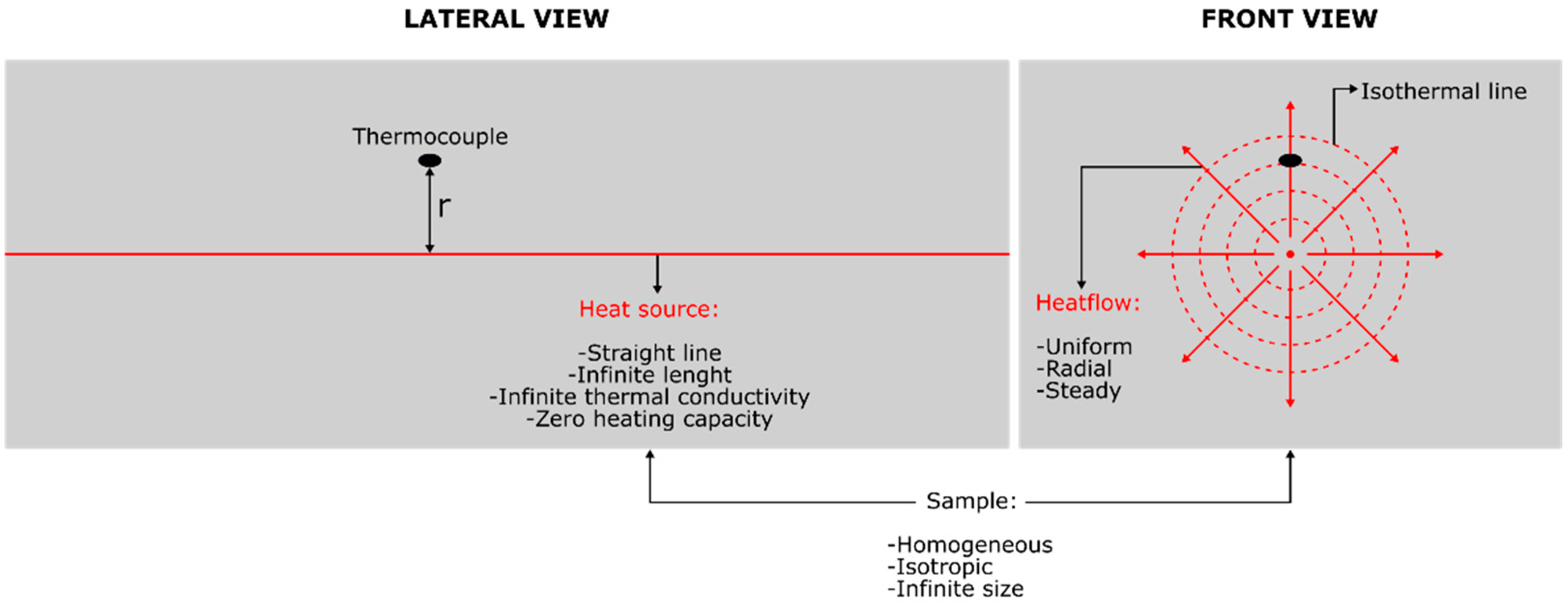
The mathematical model based on the THW method (Figure 2) assumes the following ideal conditions [12,13]:
🗸
The heat source is a straight line with an infinite length and infinite thermal conductivity. It also has zero heating capacity that dissipates a steady heat flow, which is radial and uniform;
🗸
The sample is homogeneous, isotropic and it has an infinite size;
🗸
When the trial is initiated, the sample temperature is in balance with the room temperature.
In practice the heat source is approximated by a neatly straight wire, with enough length, small diameter, high thermal conductivity, and low heat capacity. At the same time, an isotropic and big enough sample is used.
Furthermore, the determination of thermal conductivity can be wrongly measured if the time of trial is too short [14]. Equally, mistakes can occur when heat transmission is not only by conduction. Another source of uncertainty comes from not enough precision of the electronic devices [15].
Initially the THW method was used to measure thermal conductivity of gases; later on, it was also applied to the measurement of liquids and solids. As Assael et al. (2010) [16] said, it was Schleiermacher, in 1888, who possibly developed the first device, using a platinum wire with 0.4 mm of diameter and 32 cm of length, with which he measured the thermal conductivity of air, hydrogen, and carbon dioxide. Subsequently, ref. [17] employed a wire with a diameter of 0.3 mm, and a K-type thermocouple, and they measured the thermal conductivity of several liquids (alcohols, acids, etc.). A few years later, ref. [18] used it for the first time on refractory materials.
Since then, several researchers have continued working on the determination of thermal conductivity, employing commercial meters based on the THW method. In this way, [19] used a Kemtherm QTM thermal conductivity meter for the measurement of different clays. Ref. [20] also with a Kemtherm QTM measured the thermal conductivity of cement-based geothermal mortar in samples of 125 × 75 × 25 mm. Ref.[21] measured the thermal conductivity of several mortars with a QTM-500 m. Ref. [22] measured high-density concrete samples of sizes 150 × 60 × 20 mm with a Kemtherm QTM thermal conductivity meter. Ref. [23] measured the thermal conductivity of cement-based mortars with dimensions 160 × 40 × 40 mm with a Kemtherm QTM-D3 m.
Further researchers have worked in the design and construction of their homemade devices for the determination of thermal conductivity via the THW method. Ref. [24] measured the thermal conductivity of hydride powder with a diameter of 0.3 mm and a length of 15 cm. Ref. [25] obtained the thermal conductivity of zeolite bricks in samples of 7 cm length and 3 cm width using a wire with a diameter of 0.127 mm. Ref. [26] measured the thermal conductivity at high temperature of refractory bricks using a platinum wire of 108 mm length and 0.35 mm diameter. Ref. [27] used an apparatus with a platinum wire of 0.2 mm diameter for the measurement of powdery zeolite samples. Ref. [28] determined the thermal conductivity of several polymers with an apparatus in which the hot wire and the thermocouple were in parallel with a separation of 15 mm. Ref. [29] measured the thermal conductivity of fresh neat cement. They used an apparatus formed by two stainless steel wires with a diameter of 0.5 mm. Ref. [14] used a device formed by a hot wire placed at 1 mm from two thermocouples for the measurement of samples of EPS (expanded polystyrene). Ref. [30] designed an apparatus made by two platinum wires with different lengths, by which they obtained the thermal conductivity of various molten metals with an uncertainty of 2%. Ref. [12] developed an apparatus that has an accuracy of 5% and a precision of 2–3%, and it is formed by two T- type thermocouples, separated by 50 mm, and welded to a 0.508 mm diameter hot wire to test on mortars and laterite bricks. Ref. [31] measured the thermal conductivity of PMMA (polymethyl methacrylate) cylindrical samples with an apparatus that had three K-type thermocouples, and a 200 mm length and 0.3 mm diameter platinum wire. Ref. [32] measured the thermal conductivity of clay pastes used in pelotherapy with a 50 μm diameter and 21 cm length platinum wire. Ref. [33] measured the thermal conductivity of lightweight concrete produced with sawdust. They used a device in which the hot wire and the thermocouple were separated by 16 mm. Ref. [26] measured the thermal conductivity of porous materials using a nichrome wire of 300 mm length and 0.4 mm diameter, along with a Pt100 sensor. Ref. [34] used a nichrome wire with a radius of 0.095 mm, and k-type thermocouples for the measurement of the thermal conductivity of expanded polystyrene samples (EPS) and extruded polystyrene samples (XPS). [35] obtained a deviation below 3.4% when measuring the thermal conductivity at high temperature of low-density materials; they did it via a 0.5 mm diameter nichrome wire and with a K-type thermocouple. Ref. [36] measured the expanded perlite thermal conductivity via a platinum wire with 100 μm diameter and 8 cm length. Recently, ref. [37] used a 0.5 mm diameter nichrome wire and two K-type thermocouples to measure the thermal conductivity of insulating materials at high temperature.
Different commercial meters for the measurement of the thermal conductivity of solid materials, based on the THW method, exist such as concretes or refractory materials, but not specifically geothermal backfill materials. Moreover, in general these commercial meters have the possibility of measuring thermal conductivities in a very wide range, therefore its use is not suitable for geothermal backfill materials and its extensive features are consistent with its price.
Equally, commercial meters require the measurement of thermal conductivity at high temperatures, which causes them to be big and heavy due to the oven they use. In addition, commercial meters can generally measure shaped or powder materials, but not both.
The most prominent commercial meters are Shotherm QTM-F1 (from Showa Denko K.K), TCT 426 (from NETZSCH), THW-01S (from AccuInstruments), Kemtherm QTM-D3, Kemtherm QTM-500 and Kemtherm QTM-700/710 from Kyoto Electronics Manufacturing. All of them have a relative precision and accuracy between 2 and 5%.
On the other hand, as previously noted, several researchers developed their homemade devices for an intended purpose, for instance hydride powder, zeolite bricks, Polymethyl methacrylate (PMMA), etc., using complex devices and in some cases expensive ones.
This research belongs to a project of a dry mortar with nanosilica and different types of industrial waste for the application in borehole heat exchanger, of which the authors found themselves in the need of designing, building, and developing a specific device for the measurement of different produced samples. For the use in the frame of this research the device needed to be portable, in contrast with the commercially available ones, and it needed to measure the thermal conductivity in the working conditions of the BHE which rarely surpassed the 30 °C mark.
The portable device must be able to measure thermal conductivity in samples produced by mixture with components at different states, compact or powder. These samples might be suitable for their use with dry mortar for the application in BHE.
The geothermal backfill materials formed by a mixture of cement, fine aggregate, sand and/or additions are known as geothermal grouts. The aggregated additives and the other materials aggregated confer the geothermal backfill with high thermal conductivity. This characteristic is rejected in the conventional grouts used in buildings.
The necessary features are the following:
🗸
Regarding the samples:
The size: parallelepiped shape briquettes of mortar had been made with different additives. These briquettes might have the size of the sample pattern;
The state, compact or powder;
The expected thermal conductivity is relatively small, lower than 3 W/m·K, given the composition of the samples.
🗸
Regarding the test:
Repeatability;
Precision;
Heating power control;
Duration.
🗸
Regarding the apparatus:
Size;
Prize.
Nevertheless, in the scientific literature no apparatus exists that was specifically developed for the measurement of the thermal conductivity of geothermal backfill materials. For this reason, the most important aim of this paper is to develop an apparatus specially designed (range, shaped and powder materials, etc.) to measure the thermal conductivity of geothermal backfill materials based on the THW mathematical model. It must also be reliable, lightweight, economical, accurate, precise, easy to construct and easy to use. The Arduino Uno, the popular open source platform and microcontroller board, has been used for this purpose.
The novelty of the designed system is its most remarkable feature, as well as its simplicity. The precision reached is sufficient for the needs of the studies of geothermal mortars and it has proven to be highly reliable. The measurement equipment designed was used to carry out hundreds of samples of which results were previously published in [2].
Even though the components and integration described in the current study could be considered quite standard, the setup may have the potential to provide future research with useful insight into building inexpensive customized data-acquisition systems for the measurement of thermal conductivity of geothermal mortar samples.

2. Materials and Methods

In this paper, the development of a device capable of measuring the thermal conductivity via the hot wire parallel technique of the THW method is intended. This apparatus is a direct application of the ILS model.

2.1. Theoretical Basis

The starting hypothesis of the ILS model is the following: linear heat source (which is infinitely long, with zero heat capacity, and with an infinite thermal conductivity) that dissipates a radial thermal flow, constant and uniform in a medium (which is infinite, homogenous, isotropic, with initial uniform temperature and constant thermo-physical properties). It is shown in Figure 2.
It is also assumed that all heat transfer occurs by conduction, and that there are no heat sources or heat sinks. In this way, it is a one-dimensional heat transfer problem, where the governing Equation will derive from Equation (1). This equation is solved for a lineal homogeneous model [38].
1 α · T t = 1 r · r ( r · T r )
The case of temperature radial flow in geothermal mortar samples is shown in Equation (2), being r radius and t time.
T   ( r , t ) T 0 = q 4 · π · λ · r 2 / 4 · α · t e u u d u
Equation (2) allows us to obtain the temperature T   ( r , t ) at a particular point and time. This measurement depends on the initial temperature, T 0 , the heat flow per unit length,   q , the distance, r, and time, t, and the thermal properties (thermal conductivity λ and thermal diffusivity α ).
The integral in Equation (2), is called E 1 , “exponential integral function”, and it is described in Equation (3).
E 1 ( x ) = x e u u d u
The function E 1 ( x ) is named in Matlab with syntax expint   ( x ). Substituting Equation (3) into (2), Equation (4) has been obtained.
T   ( r , t ) T 0 = q 4 · π · λ · E 1 [ r 2 4 · α · t ]
where:
  • q = I · V / L heat flow per unit length; W m .
    • Where:
      I Electrical Intensity; A.
      V Voltage; V.
      L Hot wire length; m.
  • T 0 initial temperature, matching with environmental temperature at the beginning of the essay; °C.
  • T ( r , t ) temperature in time t and distance r ; °C.
  • r distance between the heat source and the temperature sensor, m.
  • λ thermal conductivity, W ( K · m ) .
In this equation’s essay all the parameters are controlled, and thermal properties can be determinated.
Therefore, the measuring apparatus must be provided with a heating system which is composed of a hot wire and a direct current (DC) power supply (to provide a constant power), a logging system, and a measuring system consisting of a temperature sensor, a multimeter for the measurement of q through intensity I and voltage V   and a flexometer for the measurement of r.
In each test, the value I is selected in the power supply and the values T and t are automatically measured.
Hence, a group of values is obtained during the test (respecting hypothesis, conditions, and approximation of the mathematical model). This group of values allows us to determine the sample thermal conductivity.

2.2. Experimental Set-Up

The developed device, named Thermal Conductivity Measuring Apparatus (TCMA), uses a hot wire as a linear heat source, dissipating thereby a radial thermal flow, uniform and constant towards the medium that constitutes the sample for testing. The hot wire is a straight metal wire with a small diameter, which is plugged into an adjustable DC power supply.
Samples are made by two test specimens, with rectangular parallelepiped shape, made of the same material and with the same dimensions.
Figure 3 shows a diagram and the placement of both test specimens of the sample during a test. Hot wire and temperature sensor are longitudinally interleaved between both test specimens.
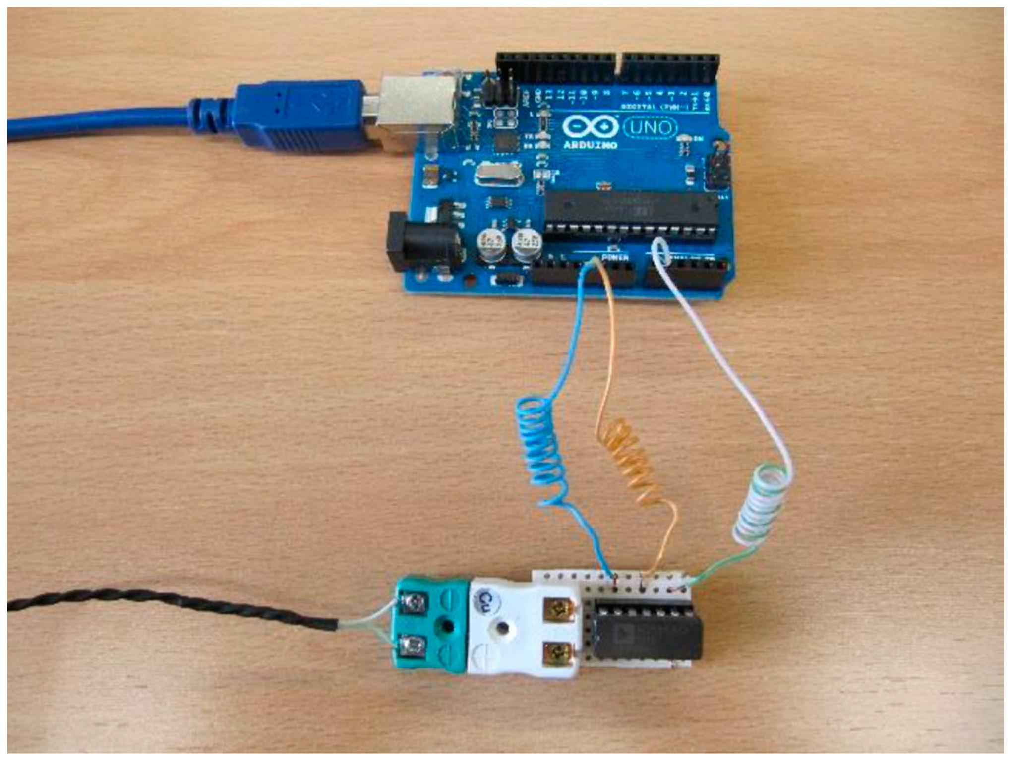
Hot wire is made of nichrome (Cronix 80 E); it has a variable length (0–510 mm) and a diameter of 0.2 mm. To change the hot wire length, adjusting it to the sample length, two crocodile clips are plugged into the adjustable DC power supply (TENMA 72–10480). The chosen temperature sensor is a K-type thermocouple (OMEGA Engineering), placed parallel at 1 mm from the hot wire, so r = 1   mm . Hot wire and temperature sensor, together with their support element, compose the measuring unit. The datalogger consists of a thermocouple connector, a 14-Pin amplifier (AD595AQ, from Analog Devices) and a microcontroller board (Arduino Uno, R3 version) connected to a PC via a USB cable. The K-type thermocouple was calibrated with an ice bath. The temperature data T and time data t measured during the tests are stored and processed on the PC for obtaining the thermal conductivity of the sample. The reader can easily find the datasheets and prices of the main components and devices used in the development of the TCMA.
For the connection of the amplifier and the Arduino Uno a perfboard and 3 wires have been used. The orange one connects Pin 11 with 5 V power of Arduino Uno, the blue one connects Pin 13 with GND of Arduino Uno, and the white–green one connects Pin 9 with A1 analog input of Arduino Uno. On the other hand, the thermocouple connector is welded to Pins 1 and 14 of the AD595AQ amplifier. In Figure 4 the measuring unit and the datalogger are shown.
Since the TCMA allows the measurement of the powder material’s thermal conductivity, it has a rectangular parallelepiped shaped container with a volume of 1800 cm3.
The TCMA auxiliary equipment is the following: 1 multimeter (for the measurement of voltage drop), 1 flexometer (for the measurement of length), and 2 crocodile clips.

2.3. Thermal Conductivity Calculation and Experimental Procedure

Equation (4) has been employed. With the already known T , r , t ,   q   and using regression methods with Matlab R2020b, the thermal conductivity λ is determined.
The experimental procedure is the following:
1.
Placement of the measuring unit sample, setting hot wire and temperature sensor between both test specimens;
2.
Placement of the 2 crocodile clips over the hot wire, with a separation equal to the length of the sample for testing;
3.
Selection of the electrical current to apply to the hot wire on the power supply. Intensity value had been estimated previously to ensure that the temperature does not exceed a maximum;
4.
Simultaneous start of the heating and data logging;
5.
Hot wire voltage drop measurement with the multimeter;
6.
Hot wire length measurement between the two crocodile clips with the flexometer;
7.
Completion of the test after 15 min of heating and data logging;
8.
Heating curve plotting;
9.
Sample thermal conductivity obtaining via Equation (4).

2.4. Validation and Calibration

During the apparatus validation and calibration, 4 commercial samples with known thermal conductivity have been employed. These 4 standard samples are:
  • Skamol SM-65 (Skamol A/S);
  • Macizo M5R (Cerámica La Espina S.L.);
  • MAXIAL 310 (RHI) y;
  • CN-90BA (Cerámica del Nalón S.A.).
Table 1 shows name, composition, dimensions, thermal conductivity λ and expanded uncertainty U c e r stated in the calibration certificates of the 4 standard samples.
These commercial samples have been chosen because of their thermal conductivity being in range.
Before the tests were performed samples were dried in a drying oven at 60 °C for 24 h. Then they were left at room temperature for 48 h, so the samples’ temperatures and room temperature were in balance.
The correct electrical current selection and minimum size selection of the samples are fundamental parameters of performing a thermal conductivity test with the TCMA. As commercial samples have different sizes, thermal conductivity tests are performed with different electrical currents (0.5 A; 1 A; 1.5 A and 2 A) to determine the minimum size needed in these samples and the appropriate electrical current in any single case.
For that, 32 thermal conductivity tests were carried out. From these essays it was concluded that using a maximum intensity of 2A ensures that hot-wire maximum temperature was not exceeded, and consequently minimizing the thermal radiation.
All thermal conductivity measurements were performed at room temperature since it is the working temperature for geothermal backfill materials. Specifically, room conditions were: 15–25 °C and 55–65% RH.
It needs to be ensured that to perform any test room temperature and sample temperature must be approximately equal. A maximum discrepancy of 1 °C has been tolerated.
Likewise, 3 thermal conductivity tests were performed in each sample, obtaining the average as a result.
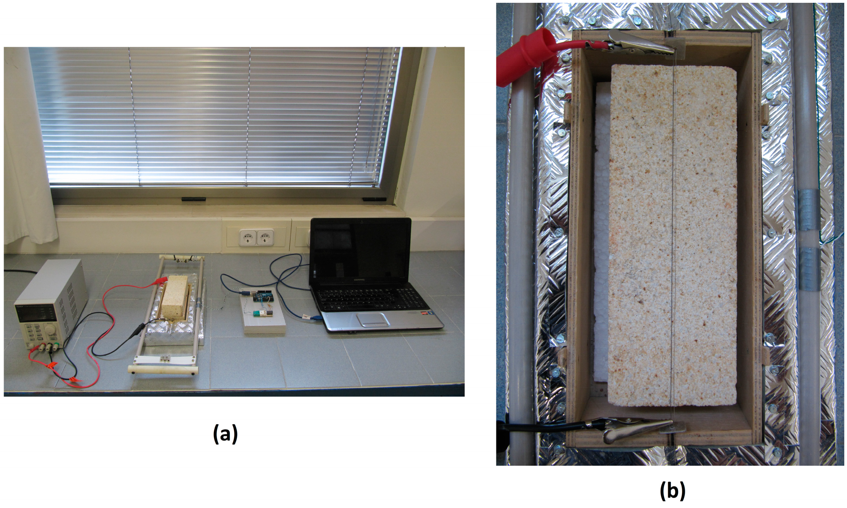
In Figure 5a a general vision of the TCMA is shown during one of the validation tests. On the right of the image the datalogger connected to the PC is placed, in the centre the measuring unit can be seen with the sample, and the power supply is on the left. In Figure 5b an in-detail view of the bottom test specimen of the sample is shown, where the hot wire, the K-type thermocouple, and the 2 crocodile clips can be seen.
After determining the minimum size of samples and the appropriated electrical current, apparatus validation is completed to determine the thermal conductivity of the 4 geothermal backfill materials traditionally used.
These commonly used geothermal backfill materials are bentonite (M 01), neat cement (M 02), cement–sand mortar (M 03) and cement–bentonite mortar (M 04).
For this purpose, the Shotherm QTM-F1 thermal conductivity meter and the TCMA have been used.
Both apparatuses are based on the THW method, allowing the comparison of the obtained results in both devices with the values reported in literature.
Materials used for the preparation of samples are: cement (c), aggregate (s), addition (b), admixture (r), and water (w). The cement employed is Portland (CEM II), the aggregate is silica sand (AS) with a maximum size of 2 mm, the addition employed is sodium bentonite (BS). A superplasticizer (sp), which is naphthalene type (RHEOBUILD 1000), has been used. Tap water was employed for the mixture of the samples. The materials employed in the samples are shown in Table 2.
In Table 3 the mix proportions (by weight) for the samples are shown.
All samples have fluid consistency. To produce 4 samples, a 5 l capacity planetary mixer (ICON) has been used. Mixing of samples M 02 and M 03 was performed for 3 min, but bentonite samples required a more energetic mixing, in special sample M 01. Each sample is formed by two rectangular parallelepiped shaped test specimens, made with the same material and with same dimensions (180 × 70 × 50 mm).
Subsequently, a sample is placed into a chamber at 20 °C and 95% RH. Samples with cement (M 02, M 03, and M 04) were demolded after 48 h of having been mixed. Meanwhile, the bentonite sample (M 01) could not be demolded until 15 days after being mixed. After that, the three samples containing cement were put into a water bath to cure for 7 days.
Before thermal conductivity tests were performed samples were dried in a drying oven at 60 °C for 5 days, and then they were left at room temperature for 48 h to bring them to room temperature.
All thermal conductivity measurements taken at room temperature. In addition, before the performance of all tests it was checked that the room temperature and the sample temperature were approximately equal. Both bricks of each sample were marked to ensure that in every test they were placed in the same position.
Three thermal conductivity tests were performed on each sample, obtaining the average as the result.
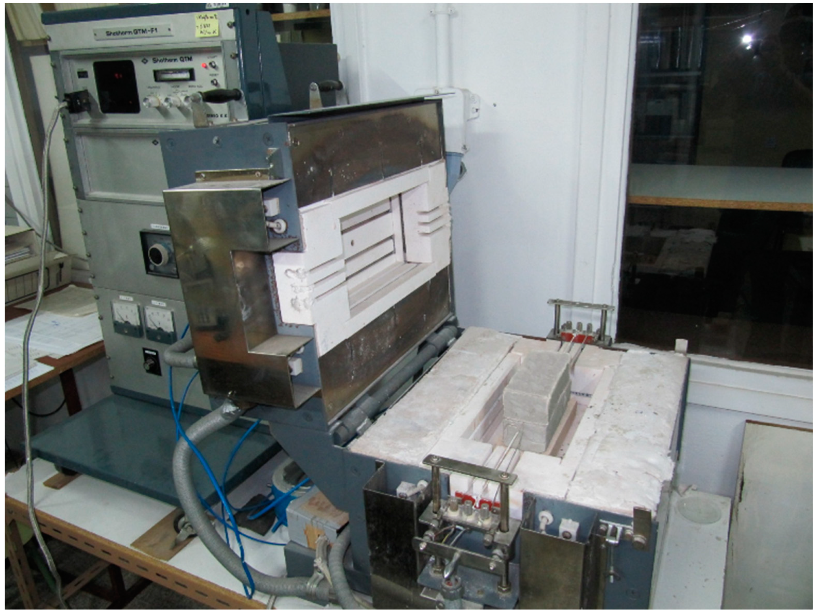
Figure 6 shows a thermal conductivity test of sample M 03 with the Shotherm QTM-F1 thermal conductivity meter.
Finally, once the TCMA is validated its calibration is executed with the aim of determining uncertainty and the calibration correction that must be applied to compensate for the apparatus bias. For that purpose, 40 tests are performed, 10 for each of the 4 standard samples.

3. Results and Discussion

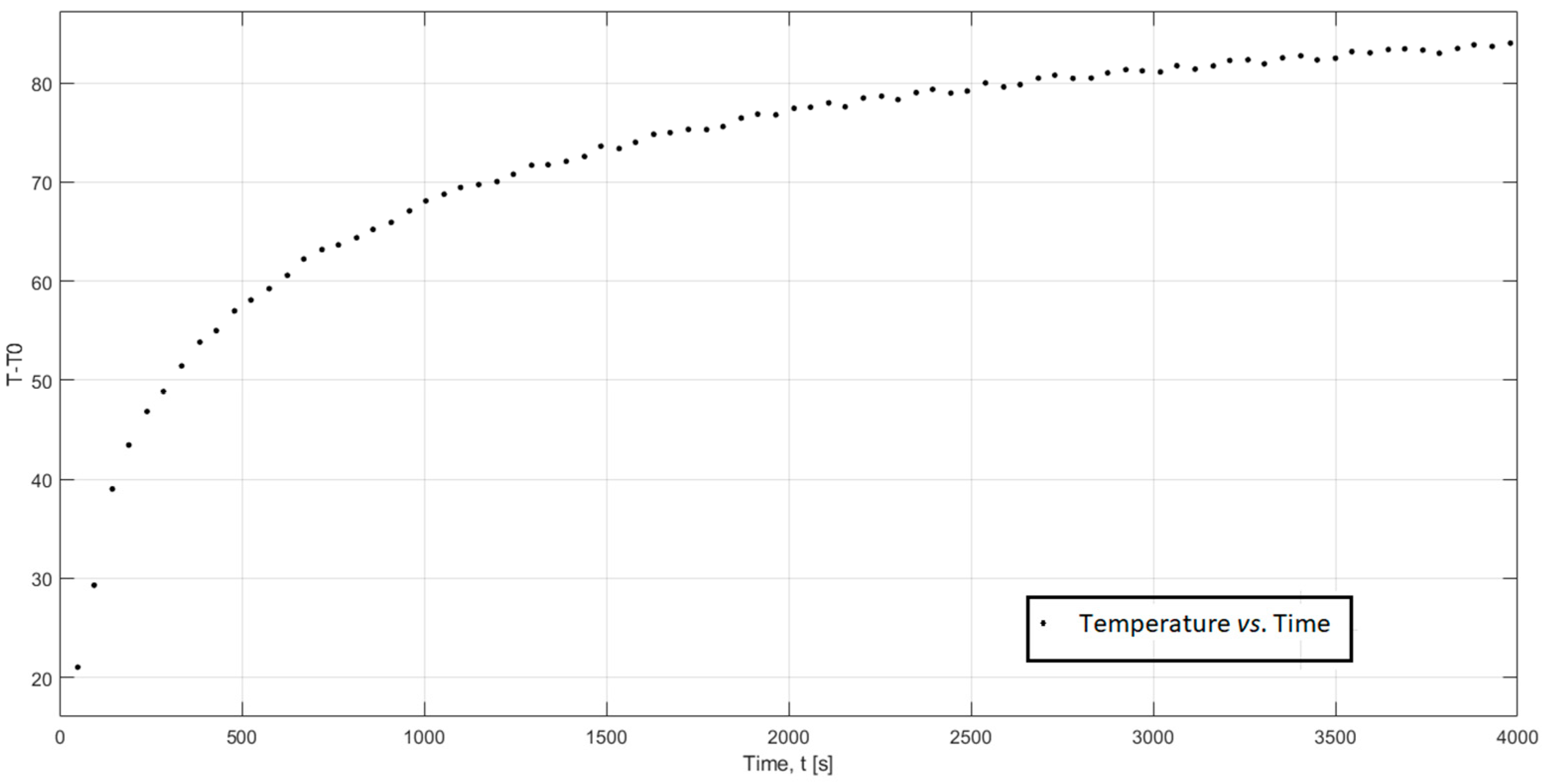
As an example of the evolution of the temperature during the TCMA test with the Skamol SM-65 sample is shown in Figure 7.
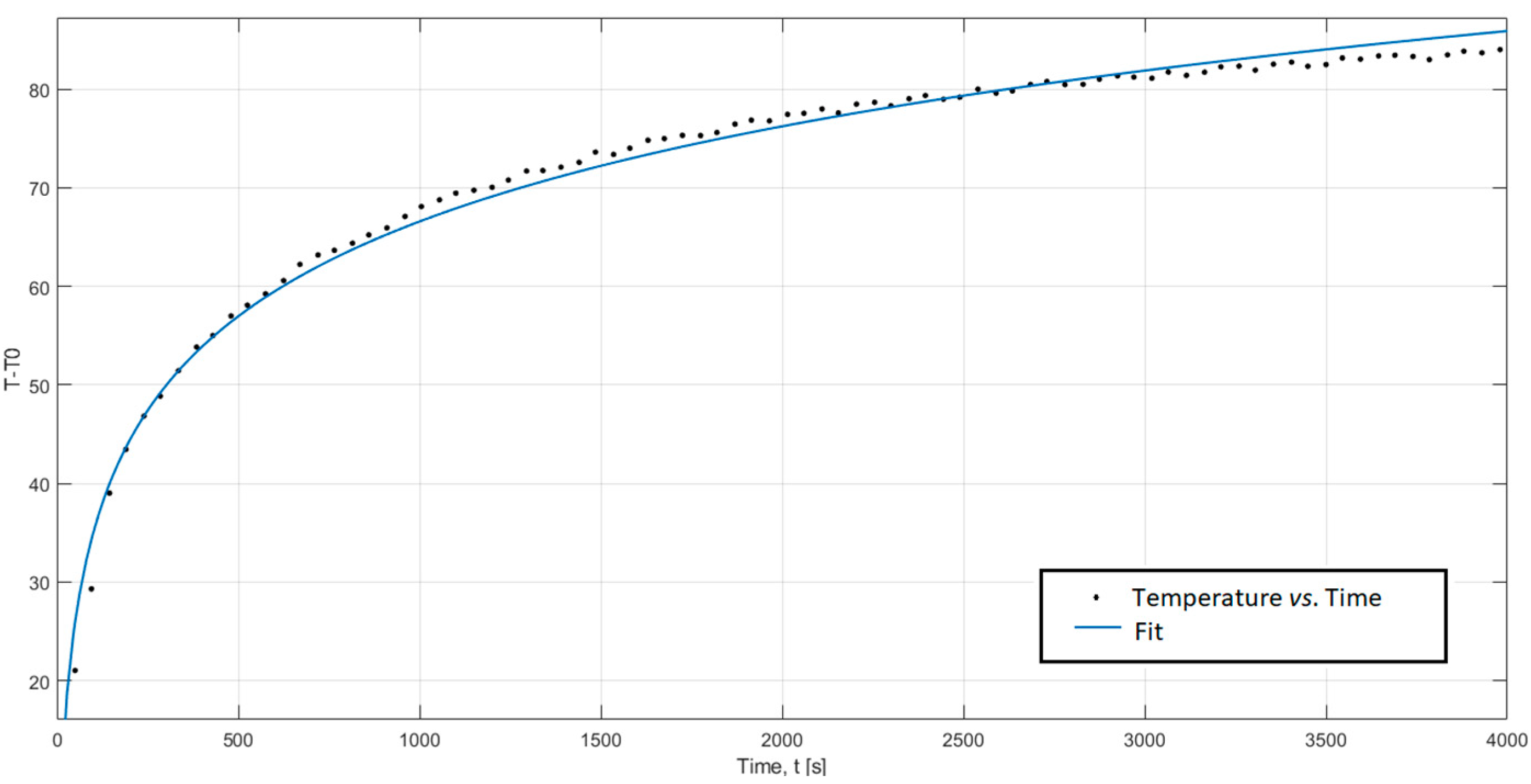
In this example q is determined from the values of the intensity of the electrical current ( I = 1   A ) , the hot wire length ( L = 0.11   m ) and the voltage drop ( V = 2.75   V ). The distance between the heat source and the temperature sensor ( r = 1   m m ). Therefore, the thermal conductivity value is calculated by the fitting regression from a Matlab Fitting Tool using Equation (4). Figure 8 shows the fit for the Skamol SM-65 sample.
As a result of the fitting regression the result of thermal conductivity is 0.1424 (0.1391, 0.1457) W/m∙K (R2 = 0.9902 with 95% confidence bounds), which is lower than the 10% value declared by the manufacturer (0.13 W/m∙K) of the sample (Table 1).
From the thermal conductivity values obtained during the TCMA validation, the minimum size of the tested samples is determined, as well as the appropriate electrical current of every test. Value deviations obtained from the TCMA are also achieved, when comparing them with values reported in literature and the values measured in a commercial meter. Finally, during the calibration, the correction of the TCMA and its expanded uncertainty are determined.

3.1. Sample Minimum Size and Appropriate Electrical Current

Using the 4 standard samples, tests were performed using 4 electrical currents (0.5 A; 1 A; 1.5 A y 2 A) that with the hot wire used in the TCMA, they correspond to the heating powers per unit length of 6 W/m, 25 W/m, 56 W/m y 100 W/m, respectively.
In Table 4 the 32 thermal conductivity values (λexp) obtained from the TCMA are shown. They were obtained by applying 4 different electrical currents (4 different heating power per unit lengths) on the 4 standard samples.
In italics, underlined, or in red bold letters the obtained thermal conductivity results are shown, according to the following criteria:
  • Italicized λexp values are those that deviate more than 10% from the reference values (λref), or those with a coefficient of determination, R2, lower than 0.95;
  • Underlined values λexp are those with a deviation lower than 10%, and value R2 is greater than or equal to 0.95, but the time window is so small that the least squares fitting is executed with less than 10 values;
  • Values λexp in red bold are those that deviate less than 10%, the value of R2 is greater or equal to 0.95, and the least squares fitting is executed with at least 10 values.
Only the values in red bold are considered to meet the criteria. In this way, after analysing Table 4 and based on established criteria, Table 5 was obtained.
  • In which if thermal conductivity is lower than 0.70 W/m∙K the minimum sample size is 110 × 50 × 35 mm and electrical current is considered appropriate both in 0.5 A and in 1 A;
  • When thermal conductivity is greater or equal to 0.70 W/m∙K the named minimum size is 180 × 70 × 50 mm, in which case, if thermal conductivity is between 0.70 and 1.20 W/m∙K, the electrical currents of 1 A, 1.5 A and also 2 A are considered appropriate;
  • Ultimately, if thermal conductivity is higher than 1.20 W/m∙K it is considered that an electrical current of 1.5 A as of 2 A is appropriate.

3.2. Comparison of Thermal Conductivity Values of the Samples

To complete the TCMA validation, the thermal conductivity of 4 commonly used geothermal backfill materials has been measured. In Table 6 the average thermal conductivity of three tests that were performed with the Shotherm QTM-F1 thermal conductivity meter and the TCMA are stated. The bibliographical data (λLiterature) were obtained from [17].
It can be observed that the measured values with the TCMA are very close to the values reported in the literature, obtaining a maximum deviation of 3% in samples M 02 and M 03. They are also very close to the values measured with the Shotherm QTM-F1 thermal conductivity meter, obtaining a maximum deviation of 4% in samples M 02 and M 04.

3.3. Calibration Correction and Estimation of Expanded Uncertainty

Four standard samples were employed for the calibration of the TCMA. For that purpose, 10 thermal conductivity measurements were performed in repeatability conditions. They were performed in 4 control points (0.13/0.70/1.20/2.80).
Chauvenet’s criterion is applied to the measurements obtained to assure that there are no outliers. Subsequently, Shapiro–Wilk test is done to prove that with a probability of 95% measurements follow a normal distribution.
In Table 7 the 10 tests average value m ¯ , the standard deviation sc, the calibration correction C, and the relative precision and relative accuracy are shown. As observed, the TCMA presents a maximum bias of 0.07 W/m·K (standard sample CN-90BA). It is also observed that in the whole range of the apparatus the relative precision, expressed through the RSD (relative standard deviation), has a maximum value of 5%, while the maximum value of relative accuracy is 3%.
Figure 9 represents in a graph the values of the calibration correction C of Table 7, which allows us to find the correction that must be applied to thermal conductivity measurements obtained with the TCMA. It can be observed that the calibration correction follows a relation that is almost linear with the thermal conductivity; the greater the correction, the greater the thermal conductivity.
The expanded uncertainty U M that will have a sample tested with the TCMA can be obtained via the graph in Figure 10, where n is the number of tests performed (1 or 3) for the measurement of the thermal conductivity.
For the obtention expanded uncertainty, U M Equation (5), has been employed:
U M = K · u = 2 · u
A coverage factor K   = 2 has been used (corresponding to a level of confidence of approximately 95%). Combined standard uncertainty u is obtained applying Equation (6).
u = ( U c e r 2 ) 2 + ( s c 10 ) 2 + ( s c n ) 2
where U c e r and s c are obtained from Table 1 and Table 7, respectively. Value n is the number of tests carried out to determine the thermal conductivity.

3.4. Summary of the TCMA Technical Specifications

In Table 8 the TCMA technical specifications are summarized.
It is worth stressing that the TCMA can be used for the measurement of the thermal conductivity of solid dielectric materials. These materials may be shaped or powder, for example, geothermal backfill materials, soils, rocks, aggregates, drill cuttings or concretes.

4. Conclusions

A device for the measurement of thermal conductivity using an Arduino Uno microcontroller board has been developed. This apparatus is based on the THW method and is specially designed to measure geothermal backfill materials. The TCMA allows the measurement of both shaped and powder form in materials with low thermal conductivity, to 3 W/m∙K.
The TCMA presents a high repeatability due to the thermal conductivity values obtained, and when testing a single sample has very little dispersion. In the studied conditions the apparatus has a relative precision of 5% and high accuracy.
Both obtained values when testing the standard samples and common-use geothermal backfill materials have at most 3% discrepancy from the values declared by the manufacturers and reported in literature, respectively.
Therefore, after validating said device it can be concluded that within the studied conditions it has a high accuracy and precision, similar to that of the Shotherm QTM-F1 thermal conductivity meter, and like that claimed by other manufactures of commercial meters.
Consequently, it is considered an option for the measurement of the thermal conductivity of the geothermal backfill materials. Moreover, the TCMA is reliable, economical, lightweight, easy to construct and easy to use.

Author Contributions

Conceptualization, T.A.-S. and M.A.R.-R.; methodology, C.C.-F., T.A.-S. and G.M.-R.; software, C.C.-F. and G.M.-R.; validation, C.C.-F., T.A.-S., M.A.R.-R., G.M.-R. and M.P.C.-G.; formal analysis, C.C.-F., T.A.-S. and M.A.R.-R.; investigation, C.C.-F., T.A.-S., M.A.R.-R., G.M.-R. and M.P.C.-G.; data curation, C.C.-F., T.A.-S. and M.A.R.-R.; writing C.C.-F., T.A.-S. and M.P.C.-G., original draft preparation, C.C.-F., T.A.-S. and M.P.C.-G.; writing—review and editing, C.C.-F., T.A.-S. and M.P.C.-G.; supervision, T.A.-S., M.A.R.-R., G.M.-R. and M.P.C.-G.; project administration, T.A.-S. and C.C.-F.; funding acquisition, T.A.-S. and C.C.-F. All authors have read and agreed to the published version of the manuscript.

Funding

This research was funded by the FICYT (Government of the Principality of Asturias) with reference BP14-074, the University of Oviedo by the project reference SV-PA-13-ECOEMP-53, and the Cátedra HUNOSA CAT-004-17.

Data Availability Statement

Not applicable.

Acknowledgments

We wish to thank the research group of the Cátedra Hunosa of the University of Oviedo, in particular Laura Cordero Llana, Saúl Norniella Llaneza, Mª Teresa Fernández González, Marina del Riego Nozal for editing and translating the article.

Conflicts of Interest

The authors declare no conflict of interest.

References

  1. Directiva 2009/28/CE del Parlamento Europeo y del Consejo, de 23 de Abril de 2009, Relativa al Fomento del uso de Energía Procedente de Fuentes Renovables y por la que se Modifican y se Derogan las Directivas 2001/77/CE y 2003/30/CE. Available online: https://www.idae.es/tecnologias/energias-renovables/uso-termico/biocarburantes/sostenibilidad/directiva-europea-de (accessed on 18 October 2022).
  2. Castán-Fernández, C.; Marcos-Robredo, G.; Castro-García, M.; Rey-Ronco, M.; Alonso-Sánchez, T. Development of a dry mortar with nanosilica and different types of industrial waste for the application in borehole heat exchangers. Constr. Build. Mater. 2022, 359, 129511. [Google Scholar] [CrossRef]
  3. Kim, D.; Kim, G.; Kim, D.; Baek, H. Experimental and numerical investigation of thermal properties of cement-based grouts used for vertical ground heat exchanger. Renew. Energy 2017, 112, 260–267. [Google Scholar] [CrossRef]
  4. Shrestha, D.; Rizvi, Z.H.; Wuttke, F. Effective thermal conductivity of unsaturated granular geocomposite using lattice element method. Heat Mass Transf. 2019, 55, 1671–1683. [Google Scholar] [CrossRef]
  5. Liang, B.; Chen, M.; Guan, J. Experimental assessment on the thermal and moisture migration of sand-based materials combined with kaolin and graphite. Heat Mass Transf. 2022, 58, 1075–1089. [Google Scholar] [CrossRef]
  6. Frąc, M.; Szudek, W.; Szołdra, P.; Pichór, W. Grouts with highly thermally conductive binder for low-temperature geothermal applications. Constr. Build. Mater. 2021, 295, 123680. [Google Scholar] [CrossRef]
  7. Kim, D.; Oh, S. Relationship between the thermal properties and degree of saturation of cementitious grouts used in vertical borehole heat exchangers. Energy Build 2019, 201, 1–9. [Google Scholar] [CrossRef]
  8. Cardoso de Freitas Murari, M.; de Hollanda Cavalcanti Tsuha, C.; Loveridge, F. Investigation on the thermal response of steel pipe energy piles with different backfill materials. Renew. Energy 2022, 199, 44–61. [Google Scholar] [CrossRef]
  9. Dong, S.; Liu, G.; Zhan, T.; Yao, Y.; Ni, L. Performance study of cement-based grouts based on testing and thermal conductivity modeling for ground-source heat pumps. Energy Build. 2022, 272, 112351. [Google Scholar] [CrossRef]
  10. Wang, S.; Li, Y.; Wu, L.; He, X.; Jian, L.; Chen, Q. Investigation on thermal conductivity property and hydration mechanism of graphene-composite cement for geothermal exploitation. Geothermics 2022, 104, 102477. [Google Scholar] [CrossRef]
  11. Hammerschmidt, U.; Sabuga, W. Transient Hot Wire (THW) method: Uncertainty assessment. Int. J. Thermophys. 2000, 21, 1255–1278. [Google Scholar] [CrossRef]
  12. Franco, A. An apparatus for the routine measurement of thermal conductivity of materials for building application based on a transient hot-wire method. Appl. Therm. Eng. 2007, 27, 2495–2504. [Google Scholar] [CrossRef]
  13. Zhang, T.; Shen, R.; Lin, C.; Yin, J.; Wang, S. Measuring moisture content in a porous insulation material using a hot wire. Build. Environ. 2015, 84, 22–31. [Google Scholar] [CrossRef]
  14. Coquard, R.; Baillis, D.; Quenard, D. Experimental and theoretical study of the hot-wire method applied to low-density thermal insulators. Int. J. Heat Mass Transf. 2006, 49, 4511–4524. [Google Scholar] [CrossRef]
  15. Dos Santos, W.N. Thermal properties of melt polymers by the hot wire technique. Polym. Test. 2005, 24, 932–941. [Google Scholar] [CrossRef]
  16. Assael, M.J.; Antoniadis, K.D.; Wakeham, W.A. Historical evolution of the transient hot-wire technique. Int. J. Thermophys. 2010, 31, 1051–1072. [Google Scholar] [CrossRef]
  17. Van der Held, E.F.M.; van Drunen, F.G. A method of measuring the thermal conductivity of liquids. Physica 1949, 15, 865–881. [Google Scholar] [CrossRef]
  18. Haupin, W.E. Hot wire method for rapid determination of thermal conductivity. Am. Ceram. Soc. Bull. 1960, 39, 139–141. [Google Scholar]
  19. Beziat, A.; Dardaine, M.; Gabis, V. Effect of compaction pressure and water content on the thermal conductivity of some natural clays. Clays Clay Miner. 1988, 36, 462–466. [Google Scholar] [CrossRef]
  20. Allan, M.L.; Philippacopoulos, A.J. Performance characteristics and modelling of cementitious grouts for geothermal heat pumps. In Proceedings of the World Geothermal Congress, Tohoku, Japan, 28 May–10 June 2000. [Google Scholar]
  21. Demirboǧa, R. Influence of mineral admixtures on thermal conductivity and compressive strength of mortar. Energy Build. 2003, 35, 189–192. [Google Scholar] [CrossRef]
  22. Esen, Y.; Yilmazer, B. Investigation of some physical and mechanical properties of concrete produced with barite aggregate. Sci. Res. Essays 2010, 5, 3826–3833. [Google Scholar] [CrossRef]
  23. Liu, K.; Wang, Z.; Jin, C.; Wang, F.; Lu, X. An experimental study on thermal conductivity of iron ore sand cement mortar. Constr. Build. Mater. 2015, 101, 932–941. [Google Scholar] [CrossRef]
  24. Ishido, Y.; Kawamura, M.; Ono, S. Thermal conductivity of magnesium-nickel hydride powder beds in a hydrogen atmosphere. Int. J. Hydrog. Energy 1982, 7, 173–182. [Google Scholar] [CrossRef]
  25. Liu, Z.Y.; Cacciola, G.; Restuccia, G.; Giordano, N. Fast simple and accurate measurement of zeolite thermal conductivity. Zeolites 1990, 10, 565–570. [Google Scholar] [CrossRef]
  26. Zhang, X.; Degiovanni, A.; Maillet, D. Hot-wire measurement of thermal conductivity of solids: A new approach. High Temp.-High Press. 1993, 25, 577–584. [Google Scholar]
  27. Griesinger, A.; Spindler, K.; Hahne, E. Measurements and theoretical modelling of the effective thermal conductivity of zeolites. Int. J. Heat Mass Transf. 1999, 42, 4363–4374. [Google Scholar] [CrossRef]
  28. Wallwork, A.; Mummery, P.; Gregório Filho, R.; dos Santos Wilson, N. Método de fio quente na determinação das propriedades térmicas de polímeros. Polímeros Ciência E Tecnol. 2004, 14, 354–359. [Google Scholar] [CrossRef] [Green Version]
  29. Mounanga, P.; Khelidj, A.; Bastian, G. Experimental study and modelling approaches for the thermal conductivity evolution of hydrating cement paste. Adv. Cem. Res. 2004, 16, 95–103. [Google Scholar] [CrossRef] [Green Version]
  30. Peralta, M.V.; Assael, M.J.; Dix, M.J.; Karagiannidis, L.; Wakeham, W.A. A novel instrument for the measurement of the thermal conductivity of molten metals. Part 1: Instrument’s description. Int. J. Thermophys. 2006, 27, 353–375. [Google Scholar] [CrossRef]
  31. Daouas, N.; Fguiri, A.; Radhouani, M. Solution of a coupled inverse heat conduction-radiation problem for the study of radiation effects on the transient hot wire measurements. Exp. Therm. Fluid Sci. 2008, 32, 1766–1778. [Google Scholar] [CrossRef]
  32. Ortiz de Zárate, J.M.; Hita, J.L.; Khayet, M.; Legido, J.L. Measurement of the thermal conductivity of clays used in pelotherapy by the multi-current hot-wire technique. Appl. Clay Sci. 2010, 50, 423–426. [Google Scholar] [CrossRef]
  33. Sales, A.; Rodrigues de Souza, F.; dos Santos, W.N.; Mendes Zimer, A.; do Couto Rosa Almeida, F. Lightweight composite concrete produced with water treatment sludge and sawdust: Thermal properties and potential application. Constr. Build. Mater. 2010, 24, 2446–2453. [Google Scholar] [CrossRef]
  34. Rixing, H.; Aichun, M.; Yahui, W. Transient hot wire measures thermophysical properties of organic foam thermal insulation materials. Exp. Therm. Fluid Sci. 2018, 98, 674–682. [Google Scholar] [CrossRef]
  35. Jannot, Y.; Degiovanni, A. An improved model for the parallel hot wire: Application to thermal conductivity measurement of low density insulating materials at high temperature. Int. J. Therm. Sci. 2019, 142, 379–391. [Google Scholar] [CrossRef]
  36. Rottmann, M.; Beikircher, T.; Ebert, H.P. Thermal conductivity of evacuated expanded perlite measured with guarded-hot-plate and transient-hot-wire method at temperatures between 295 K and 1073 K. Int. J. Therm. Sci. 2020, 125, 106338. [Google Scholar] [CrossRef]
  37. Jannot, Y.; Degiovanni, A.; Schick, V.; Meulemans, J. Apparent thermal conductivity measurement of anisotropic insulating materials at high temperature by the parallel hot-wire method. Int. J. Therm. Sci. 2021, 160, 106672. [Google Scholar] [CrossRef]
  38. Carslaw, H.S.; Jaeger, J.C. Conduction of Heat in Solids, 2nd ed.; Oxford University Press: London, UK, 1959. [Google Scholar]
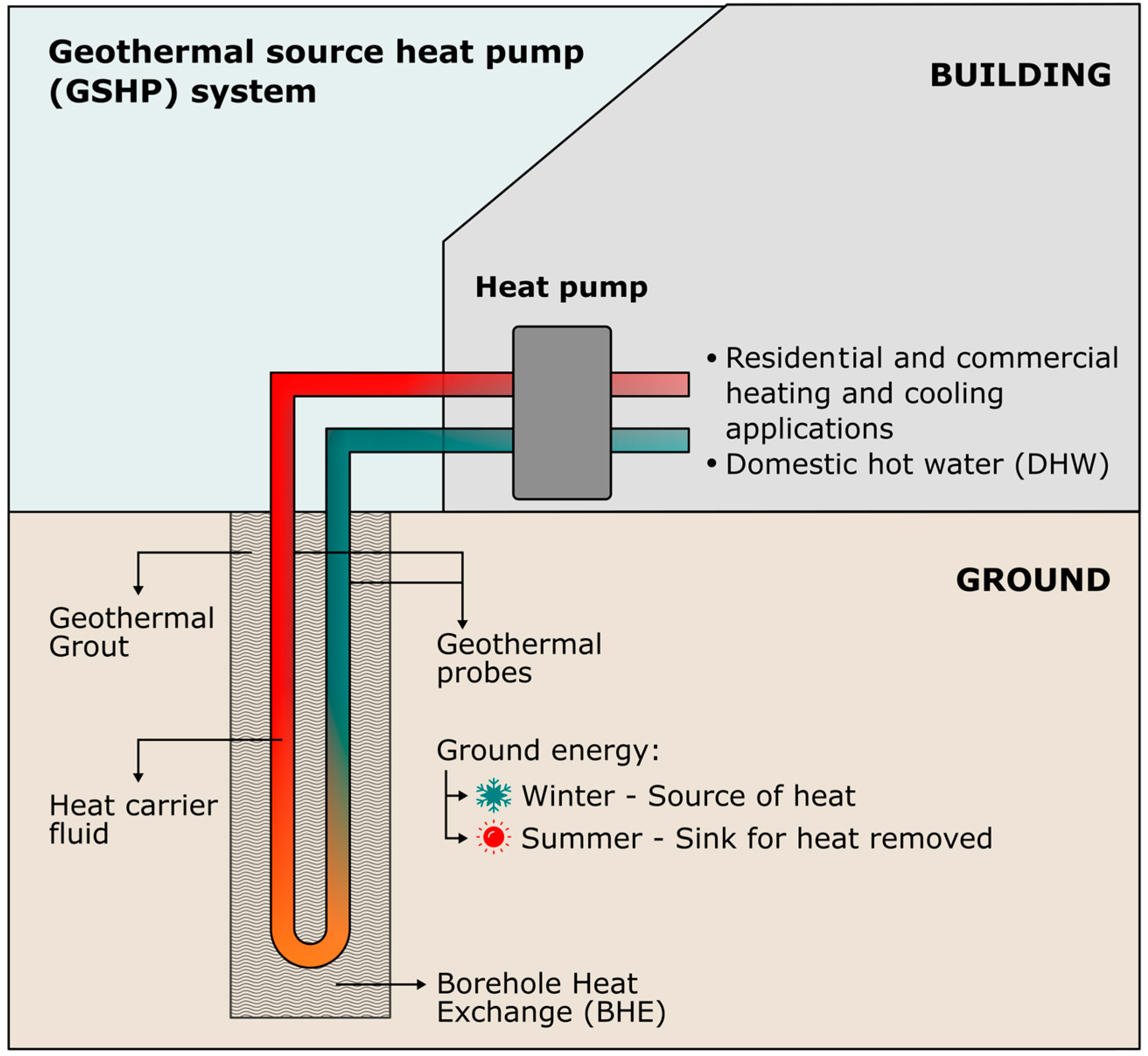
Figure 1. Geothermal source heat pump.
Inventions 08 00030 g001
Figure 2. Lateral and frontal sample view in the THW mathematical model.
Inventions 08 00030 g002
Figure 3. Diagram of the TCMA (top view) and sample disposition.
Inventions 08 00030 g003
Figure 4. Datalogger.
Inventions 08 00030 g004
Figure 5. (a) TCMA. (b) Detail of the lower test specimen.
Inventions 08 00030 g005
Figure 6. Shotherm QTM-F1 thermal conductivity meter.
Inventions 08 00030 g006
Figure 7. Heating curve. Skamol SM-65 sample.
Inventions 08 00030 g007
Figure 8. Fit for the Skamol SM-65 sample.
Inventions 08 00030 g008
Figure 9. Graph for obtaining the calibration correction in the TCMA.
Inventions 08 00030 g009
Figure 10. Graph for obtaining the expanded uncertainty with the TCMA.
Inventions 08 00030 g010
Table 1. Commercial samples features used in validation and calibration.
SampleCompositionSize [mm]λ [W/m∙K] U c e r   [W/m∙K]
Skamol SM-65DiatomiteSmall: 110 × 50 × 350.130.00
Macizo M5RRed claySmall: 110 × 50 × 35
Medium: 180 × 70 × 50
Large: 240 × 120 × 60
0.700.01
MAXIAL 310ChamotteMedium: 180 × 70 × 501.200.02
CN-90BAAluminaSmall: 110 × 50 × 35
Medium: 180 × 70 × 50
Large: 240 × 120 × 60
2.800.04
Table 2. Materials used in M 01, M 02, M 03 and M 04.
SampleMaterials
CementAggregateAdditionAdmixture
csbr
M 01------BS---
M 02CEM II------sp
M 03CEM IIAS---sp
M 04CEM II---BSsp
Table 3. Mix proportions for M 01, M 02, M 03 and M 04.
SampleMix Proportions
s/cb/cw/bw/cr/c
------4------
M 01---------0.250.02
M 022------0.450.02
M 03---0.20---0.520.02
M 04
Table 4. Thermal conductivity obtained with the TCMA in the standard samples.
Standard Samplesλexp [W/m∙K]
Sampleλref [W/m∙K]Size
[mm]
Electrical Current
Heating Power per Unit Length
0.5 A 6 W/m1 A 25 W/m1.5 A 56 W/m2 A 100 W/m
Skamol SM-650.13110 × 50 × 350.130.130.140.14
Macizo M5R0.70110 × 50 × 350.750.680.670.67
180 × 70 × 500.640.750.730.69
240 × 120 × 600.650.660.700.65
MAXIAL 3101.20180 × 70 × 500.901.231.231.25
CN-90BA2.80110 × 50 × 351.672.032.742.97
180 × 70 × 503.912.052.932.85
240 × 120 × 603.483.522.972.76
Table 5. Sample minimum size and appropriate electrical current of the TCMA.
λ [W/m∙K]Sample Minimum Size [mm]
<0.70110 × 50 × 35
≥0.70180 × 70 × 50
λ [W/m∙K]Appropriate Electrical Current [A]
<0.700.5/1
0.70–1.201/1.5/2
>1.201.5/2
Table 6. Thermal conductivity measurements and deviations.
SampleλLiterature [W/m∙K]λQTM-F1 [W/m∙K]λTCMA [W/m∙K]λTCMA
Deviation to λLiteratureDeviation to λQTM-F1
M 010.700.710.700%−1%
M 020.800.790.82+3%+4%
M 031.531.631.58+3%−3%
M 040.800.840.81+1%−4%
Table 7. Values obtained during the calibration of the TCMA.
TCMA
[W/m·K](%)
Standard Samples m ¯ sc C Relative PrecisionRelative Accuracy
Skamol SM-650.130.0070.0050
Macizo M5R0.720.034−0.0253
MAXIAL 3101.240.034−0.0433
CN-90BA2.870.077−0.0733
Table 8. Technical specifications.
MethodTHW
Range0.13–2.80 W/m∙K
Samples minimum size(110 × 50 × 35) mm3 (≤0.70 W/m∙K) (180 × 70 × 50) mm3 (>0.70 W/m∙K)
Material for testingSolid dielectric materials
Relative accuracy3%
Relative precision5%
Test duration<15 min
Hot wire materialNichrome
Hot wire lengthVariable: (0–510) mm
Hot wire diameter0.2 mm
Power supply amperage(0–3) A
Temperature sensorK-type thermocouple
Temperature sensor diameter0.1 mm
Distance hot wire–temperature sensor1 mm
Dimensions600 × 500 × 260 mm
Weight10 kg
Operating Environment(0–45) °C and (30–80)% RH
Disclaimer/Publisher’s Note: The statements, opinions and data contained in all publications are solely those of the individual author(s) and contributor(s) and not of MDPI and/or the editor(s). MDPI and/or the editor(s) disclaim responsibility for any injury to people or property resulting from any ideas, methods, instructions or products referred to in the content.