Abstract
The following scientific paper aims to analyze in detail the methodology for reverse engineering of a racing motorcycle connecting rod. The objective is to start with a product available on the market as a spare part, reconstruct its CAD model with a high standard of accuracy, then proceed with lightening modifications to arrive at a new, improved design. The innovative aspect of the procedure lies in the fact that in order to ensure accuracy on the order of a tenth of a millimeter during reconstruction, it was decided to use a FARO articulated arm laser to scan the component’s outer surface. By taking advantage of appropriate redesign CAD software (Geomagic Design X), a reconstruction can proceed within the high standard of accuracy imposed. In conclusion, the modifications made through material removal allow an improvement in product efficiency, ensuring high performance.
1. Introduction
In the industrial world, the term “reverse engineering” denotes a particular type of design that does not follow classical design practice [1]. Typically, when a company chooses to introduce a new product to the market, it follows the progress of the design from the definition of one or more concepts to the manufacture of the parts. The product must fulfill all the functionalities for which it was designed (real market needs) in the optimal way. Simply put, it is understood that over its lifetime it should be the best solution for a consumer who needs to choose among all existing products that can satisfy a particular need [2]. The need to innovate now touches any business operating in its field. For this reason, numerous methodologies have been established over the years to ensure that the product being fabricated is competitive once it is marketed. The most important methodologies to mention are Quality Function Deployment (QFD) [3,4] and Benchmarking, tools useful for defining from the outset the level of product quality in relation to a comparison with competitors. Design for Six Sigma (DFSS) [5,6], Theory of Inventive Problem Solving (TRIZ) [7,8], and Industrial Design Structure (IDeS) [9] are three other examples of tools capable of guiding the product development process within a company.
A well-known fact in the literature is that the life of a product is divided into several phases [10,11]. The first concerns its introduction to the market. This is followed by the development phase, the maturity phase, and finally the phase of its inevitable decline caused by the introduction of other products on the market that are better and cutting edge. Such new products can fulfill the same functionality as the first one, if not more, and more effectively. It may happen that a company opts to attempt a “relaunch” of the product, withdrawing it from the market for a period strategically useful for the development of a more innovative version of it. This is where reverse engineering comes in. This methodology is applied on products already on the market. When this happens, their decline is not always already underway. Very often, in fact, the approach to a re-engineering of a product is conducted by a company that does not yet produce it, to enter the market with new design solutions [12]. In some cases, the need to reconstruct the CAD model of a part arises because the 2D and 3D drawings of the part are no longer present within the company’s databases. This is something that happens more often than one might think. Suffice to say that much of the information content of mechanical components marketed by a company is contained in 2D drawings on paper.
The goal in each case is to improve something that already exists. For example, choosing materials other than those already used within product architecture can lead to lower production costs, better ease of disposal of components at the end of their useful life, or weight optimization. In the case of mechanical parts that are part of complex systems (such as an engine), light-weighting is almost always the main objective since this type of optimization directly affects the final performance of the assembly. Currently, reverse engineering of a component is possible due to the increasingly advanced CAD modeling systems, virtual prototyping environments within which the definition of complex and innovative geometries, the simulation of their mechanical behavior due to finite element analysis (FEM) and a good prediction of their fatigue life are made possible [12]. The interfacing of a CAD with virtually all company departments directly involved in the design of a part then represents a pivotal tool for product lifecycle management (PLM). For this reason, prototyping virtually is the first step in redesigning a geometry to near perfection. Very often, the final quality of the reverse reconstructed component is particularly low [13]. This happens because one focuses only on obtaining a replica of it without first defining a set of parameters that can determine the acceptability of the result. The mere use of a gauge, for example, does not allow high-level reconstruction of a geometry. This is because at the time of measurement itself to the error that the instrument carries must be added that of the human hand. Basically, a high-resolution caliper can admit a particularly high level of accuracy, on the order of a tenth of a millimeter or even less. However, to think of relying solely on the use of a caliper to measure all dimensions of the part to be reconstructed does not work if the goal is to remain within a very small tolerance range at every point on its surface. In this case, an acceptance level of the final result with a gap of no more than a tenth of a millimeter from the original part was pre-defined at the beginning of the project.
In addition, the reconstruction of a fully parametric model represents the best possible outcome for a designer. The goal is not only to obtain a mathematical model of the scanned component, rather it is to possess all the CAD features that can lead to the definition of the geometry [14,15]. This is the only way to take full advantage of the flexibility to modify it according to the required design needs. This is possible thanks to the progress the CAD modeling world has witnessed in recent years, with the development of new modules designed for reverse engineering capable of rebuilding solids and surfaces almost autonomously from the analysis of scanned point clouds [16].
For this reason, the use of a blue light laser scanner can represent a good technical tool. In fact, it allows the measurement process to be freed from the error associated with the human hand, speeds up the entire reverse-dimensioning process, and is able to capture the details of almost every geometric detail of the part, even those marked by the most articulated shape [17]. One of the positives of laser scanning technology is based on two aspects: The first concerns the state of technological advancement that tools of this type can provide to designers. As already known in the literature, the level of accuracy achievable by scanning the surfaces of even very complex geometries is unrivaled [18,19]. The best lasers on the market guarantee scanning tolerances of no more than 0.05 mm. This means that near-perfect scanning of any geometry is made possible. The second aspect arises from this consideration. There are no practical limits imposed by the geometric complexity of a scanned surface or the material of which it is fabricated. This suggests that there are no limitations to carrying out the process of reverse engineering using a laser scanner. Obtaining a point cloud capable of fully representing a complex component such as an engine crankcase, cylinder head, crankshafts, camshafts, and so on, provides the CAD modeler with a complete model on which redesign or optimization can be efficiently performed. Starting from a more accurate and detailed mesh of the original model, it is possible to redesign in a safer and more reliable way. CAD reconstructions of dissimilar and inaccurate digital twins of real products bring the designer into a state of greater uncertainty from the earliest stages of study about the geometry, mechanical behavior, and functionality of the original product. The accuracy of the mesh depends on the quality of the laser and the number of points that can be scanned. This is both dependent on the laser and on the computational and storage capabilities of the computer being worked on. Very often it is easy to exceed one million scanned points even on modestly sized components [20].
In connection with this, the content of the following paper concerns precisely the reconstruction of a motorcycle connecting rod of which the virtual model was not possessed. Reconstructing it by admitting a maximum point gap of 1/10 of a mm was the initial goal, given its application context. Optimizing it from a weight standpoint was the ultimate goal, given the need for its improved performance within the engine. Issues inherent in the sizing of a component such as the connecting rod is not addressed here. In fact, the work focuses on the analysis of the results obtained following laser scanning and reconstruction of the part to which several shape level modifications were applied to optimize its performance.
2. Materials and Methods
The connecting rod is a mechanical component of fundamental importance within an engine. The one under consideration belongs to a KTM 85cc 2-stroke. It has two holes for connection to the crankshaft and piston pin; there is a needle bearing in both and lubrication is provided by the oil–gasoline mixture. Given the high number of revolutions at which the engine runs and the pressure load resulting from high pressure peak in the combustion chamber, it is understandable that it is a particularly stressed mechanical organ. However, an excessively massive connecting rod generates very high stress values on the crankshaft bearings, particularly at bottom dead center (BDC). At top dead center (TDC) in a two-stroke engine, pressure is always present in the chamber and therefore the inertial forces are partly reduced by the pressure present. With a view to minimize the overall weight of the moving parts to allow higher acceleration values, excess material must be avoided at all costs so as not to adversely affect vehicle performance. Weight reduction also entails the need to rebalance the crankshaft to avoid vibrations due to incorrect compensation of the translating masses. The connecting rod considered in this work is one piece and has no screws on the head, as the basic shaft is decomposable.
This component is by its very nature subject to tight tolerances at almost all points. Undoubtedly, the most important areas are those connecting with the other components already mentioned (piston pin and crankshaft journal). In general, surface imperfections and cracks must be completely absent. As a component subject to cyclical loads, its fatigue life is drastically compromised. For this reason, a virtual reconstruction must take a rigorous and flawless practice to ensure accurate processing followed by appropriate surface treatments. By minimizing the error at this stage, it is possible to proceed with reshaping the part. Again, the aim is to minimize an error, but of a different kind. Whereas before, reference was made to a measurement error (related to a deviation between the actual surface of the part and the scanned surface), now a reconstruction error must be avoided (in the sense that even with an ideally perfect and error-free scan, it is possible that the CAD reconstruction of the geometry will be performed inaccurately).
As mentioned earlier, the use of a blue light laser scanner is the best solution to minimize the overall final error on model reconstruction from the early stages of reverse engineering [21]. Using a scanner is useful to quickly derive the shape of the outer surfaces of an object. A series of points are thus derived as output and can be used to create a mesh that can represent the part [22]. The laser used for scanning the connecting rod is the FARO Quantum S, which is equipped with a blue light and a probe (the latter is equipped with a spherical probe useful for detecting by direct contact the points on the surface of the component). The manufacturer’s stated level of resolution is half a tenth of a millimeter, so it is perfectly consistent with this type of application. Resolution is an indicative level of the accuracy of such technology. If five-hundredths of a millimeter is guaranteed by the manufacturer, it means that any point scanned is no farther than 0.05 mm from the ideal surface obtained from the scan [23]. An ideal surface is defined as one obtained from a scan completely free of defects. The connecting rod was initially cleaned to remove residual dust or grease from its surfaces. This step is particularly important because the presence of such elements causes them to appear in the STL mesh of the scan, as if they were an integral part of the connecting rod. Next, it was scanned from both sides, and then the scans of the two halves were aligned and joined using Geomagic Design X 2022 software (designed specifically for reverse engineering). The use of software programmed specifically for reverse engineering ensures a reconstruction of the model surfaces through a process of mathematical interpolation or extrapolation. Thus, CAD software designed for traditional design (forward engineering) is not the optimal solution for this type of problem. The entire procedure is found to be heavily affected by error in all its stages, starting with scanning.
For this very reason, the final mesh was not obtained with only one scan attempt. To obtain a quality mesh more tries should be made by mainly exploring different light conditions and component positioning.
In this way it is possible to obtain better scans than others. Particularly, bright lighting, can cause many reflections and consequent distortions and errors on the scans. The positioning of the component so that its geometry is more accessible also makes more details visible to the laser and improves the quality of the mesh. Vibration from the environment causing small movements of the component on the laser bench represents another problem. Multiple scans increase the probability of obtaining one performed under perfect static conditions of the part. However, there is no universally valid method for understanding what are the best conditions under which to scan. The quality of the result depends directly on the experience and good practice of the person who performs the scan. After the scan is correctly performed, remodeling of the part can be performed. However, before continuing a few dimensional surveys should be performed on the component. The main dimensions of the component can be detected with the software’s internal measurement tools to check their compatibility with the scan and eventually provide an initial assessment of the quality of the scan (and the error this process already caused). The software can recognize at the outset some primitive geometries on the model, such as planes, revolutions, cylinders, toroidal surfaces, and tapering. This can be seen in Figure 1.
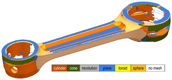
Figure 1.
Detection of some primitive surfaces performed by the software.
The next step is to identify any component symmetry planes and/or reference principal planes for the final CAD model. This step is very important and very often skipped. The presence of symmetries should absolutely be considered as it influences several aspects related to both modeling and possible future simulation of the mechanical behavior of the component [24]. Knowing that a geometry is symmetrical halves its modeling time. With a classic “mirroring” operation, which is allowed in any CAD software, half of the geometry can be mirrored to the point where the modeling of the part is directly terminated. In addition, the presence of “useful” geometric planes and axes facilitates the study of the part within other software designed to predict its ability to resist stresses, such as finite element analysis (FEA) software [25]. Importing a misaligned geometric model into software outside the CAD in which it was designed almost always makes it unusable.
The inherent remodeling step then leads to obtaining a mathematical model (such as a Step, Iges, Parasolid, or CAD-specific file). The extrapolation of axes and planes of the model is performed by a mathematical process of minimizing the distance of N points from a surface or a straight line, as appropriate. In case one wants to extract a plane aligned to a model surface, for example, one can proceed by selecting several points belonging to it. In case there are only three (not aligned), it is trivial to infer that the equation is that of the plane passing through three points.
Imagining that the three data points are A(xa; ya; za), B(xb; yb; zb), and C(xc; yc; zc), it is possible to proceed by considering that the vectors A-B and B-C belong to the plane. As known, their vector product returns a normal vector to the plane of coordinates (a, b, c). They are precisely the parameters that appear in the general equation of the plane. At that point, by imposing the transition to any of the three points, the value of the last unknown parameter (k) can be derived.
However, such a selection does not detect a sufficiently large sample of points to represent the reference surface in a statistically valid manner. Therefore, it is necessary to proceed by selecting a multitude of them, thus trying to derive the equation of the plane that minimizes the distance from them. A representation of this problem is provided in Figure 2 for clarity.
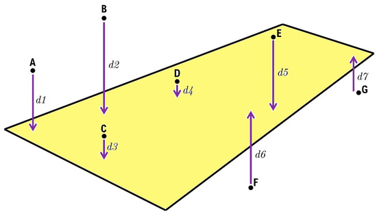
Figure 2.
Representation of N points belonging to a plane surface together with the plane extrapolated to represent it.
Imagining N points (A, B, C, D…) belonging to a plane surface, their distances from the hypothetical plane representing it are d1, d2, d3, and so on. The goal is to ideally bring all these distances to 0 and have a plane passing through all the given points. However, due to obvious surface defects of any mechanical component and considering the errors of a measuring instrument such as a laser scanner, it is clear that those points never all belong to the same plane. Then, given a known initial plane, one can think of an error function E that depends on all point distances from that plane.
Proceeding iteratively, it is possible to arrive at the plane that minimizes that function. In this function, the distances are considered as positive, unsigned numbers. It follows that the resulting plane does not necessarily pass through all the selected points (potentially none) but is equally the one that best approximates the plane surface under consideration. The same reasoning applies when the research of a plane of symmetry is conducted. In that case, it is important that the points of the selected scan belong to an effectively symmetrical mesh. On the scanned mesh, the lack of numerous points in the areas of the connecting rod end and head was evident. This is because the laser cannot cover a hole through its entire depth, especially if its diameter is relatively small. Because of this, it was preferred to isolate the connecting rod shaft (found to be complete) to derive the two main planes of symmetry of the part. Isolating only one part of the component in a sub-mesh (as long as it is always symmetrical) is a good strategy to minimize the computational error on the plane of symmetry. In fact, it is easy to see that if absurdly the points of all one half of the part were missing, it would be impossible to possess the mathematical data regarding their positioning in space and thus derive a plane of symmetry by involving them in the calculation.
On Design X, this process requires drawing by hand an initial plane of symmetry. This is only a first attempt useful for speeding convergence to the optimal solution calculated iteratively by the software. As can be seen in Figure 3 the connecting rod was isolated, then the true plane of symmetry was drawn, acquiring the hand-drawn first attempt plane and the symmetric mesh as input.
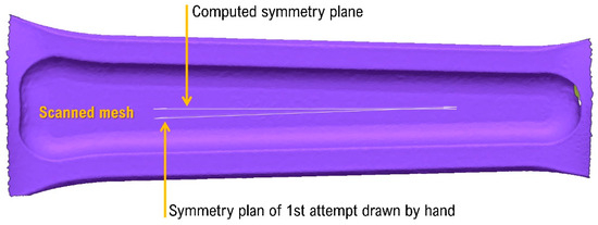
Figure 3.
Extrapolation of the symmetry plan.
Having found the symmetry planes of the mesh, it is important to proceed with aligning those planes with those already present within the software interface. In fact, as already mentioned it is important to perform the reconstruction of the geometry following the logic of the symmetries and the most important geometric elements of the component. For example, the center of the model origin was fabricated to coincide with the center of the connecting rod head bore as shown in Figure 4.
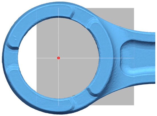
Figure 4.
Alignment of the scan to CAD model planes an origin.
Figuring out which features to apply to arrive at a geometry ever closer to the one to be obtained is a very complicated process: very often the actual order of the features changes the final result of a shape.
Small errors can cause issues that are often discovered too late. In particular, it is important to pay attention to the alignment of each plane, axis, and surface extracted, as mathematical results are dictated by the computation of an average applied to the positioning of a series of points in space. Any extracted elementary geometry whose orientation is known must therefore be corrected after extraction.
Another common difficulty due to the Design X software computation is related to the fact that the geometric dimensions detected on the scan are provided with abundant significant figures, so it is ambiguous to define the new design dimension associated with a particular feature (for example, the diameter of the hole in the connecting rod head). This error on the order of one tenth of a millimeter can be due to a laser defect, or an alignment between two scan parts performed too roughly. However, with exact reconstruction of the part being the goal, it is necessary to verify the dimensions at the design stage. An example of reverse sizing is presented in Figure 5.

Figure 5.
Extrapolation of a hole diametral dimension analyzing the point cloud.
Considering holes, these CAD features are represented by cylinder equations.
The points xc and yc represent the center of the base circle of the radius equal to R placed on the xy plane. The axis is normal to that plane and passing through the point (xc; yc) is precisely the axis of the hole. A spherical surface is represented by a different equation.
R is the sphere radius, and (xc; yc; zc) is the center of the sphere in the virtual space. In the case of a conical surface, the equation governing the distribution of points on a surface change again and it is as follows.
This type of equation accounts for geometric details typical of mechanical components such as countersinks for holes and chamfers fabricated along the model edges.
3. Results
Even cutting-edge technology such as laser scanning has its limitations. For example, it is not always possible to scan every point on the surface of a part. Particularly deep and narrow holes present an obstacle for the light beam. However, it is not always necessary to have a complete, closed mesh at every point. For example, it is sufficient to have only a part of a hole (center position and diameter) scanned, as shown in Figure 6, to know all the information about it.
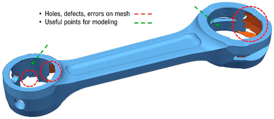
Figure 6.
Mesh error example and high information content areas for modeling.
After performing each feature to obtain the final shape of the component, it is compared with the mesh obtained from the scan (Figure 6). This step is useful to highlight the areas that are most distant from the original. In some cases, even a deviation of 1 mm, for example, is acceptable in the case where a series of changes on the geometry follow to design a different component from the starting one. In case, on the other hand, the mechanical behavior of the connecting rod is to be simulated, such a gap is not acceptable to obtain likely correct data at the end of the structural analysis performed on the geometry.
From the overlay between the CAD model and the starting mesh, it is possible to obtain an idea of the effectiveness of the reconstruction. There are some areas where the mesh is above the surface of the model. In this case, the comparison between the two models has a negative deviation value. On the contrary, in the areas where there is an excess of material, there is a positive deviation. This finding is shown in Figure 7.
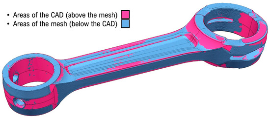
Figure 7.
Comparison between CAD model and scanned mesh.
However, positive feedback is not to be considered valid. It is always necessary to define a maximum tolerable deviation range at the outset. Given a deviation of one-tenth of a millimeter as the objective of the connecting rod reconstruction, the goal was obtained over 90% of the component surface, as shown in Figure 8 (in green). In some places (in yellow) further modifications to the model are required to increase the quality of the result and reduce the gap, which is more than two-tenths of a millimeter. On areas of the mesh not scanned because of laser limitations, a comparison is obviously not possible (in purple).
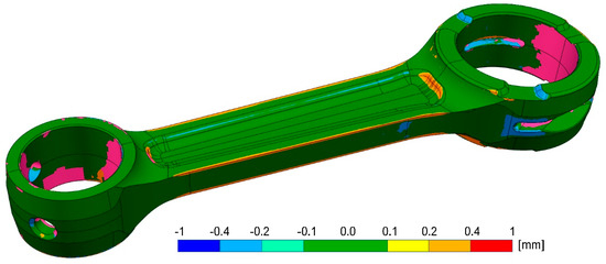
Figure 8.
Mesh matching analysis post-remodeling.
Having verified the quality of the model, the design of the component is modified. In the case of the connecting rod, lightening is always one of the most important objectives. A light connecting rod is subject to less inertial loads and improves vehicle performance, allowing it to accelerate more. However, removing material from a component causes a decrease in its stiffness and its ability to resist stresses. If the stiffness drops, the part is more yielding, so it deforms more when subjected to external loads. For this reason, this design/optimization phase is particularly critical, as it is necessary to arrive at the best compromise.
The subject of the following work does not to go into the design and dimensioning of a connecting rod [26]. The most important thing is to understand in which areas one can act to remove material. One of the starting constraints is that of symmetry; the part is originally symmetrical and remains so until the end of the design. An asymmetrical connecting rod would cause excessive imbalance on the crankshaft and piston, undoubtedly worsening engine life.
First, material was removed from the circular edge of the connecting rod end, as show in Figure 9.
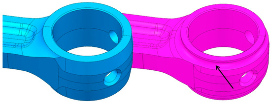
Figure 9.
Material removed on the connecting rod end.
Material was also removed on the connecting rod head to promote lubrication of the needle bearing. This was intended to make an opening with no sharp edges in the final model, which would otherwise locally increase the tensional state within the material. Finally, material was also removed from the edge of the connecting rod head in the same way as was performed on the end, as shown in Figure 10.
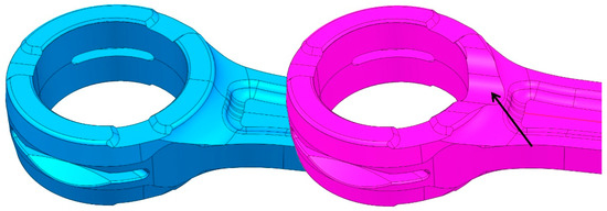
Figure 10.
Modifications on the connecting rod head.
Having completed the structural modification phase of the connecting rod, its verification can be carried out. Finite element simulations are useful for a prediction of the fatigue durability of the component. However, directly testing the physical prototype is always the best solution, as it provides real information of the reliability of the component. Numerical data and forces used in the simulation for the prediction of connecting rod fatigue life can be found in Table 1. As can be seen, it is essential to make a correct estimate of the maximum tensile and compressive loads to which it will be subjected in order to correctly and confidently estimate whether this component can resist stress.

Table 1.
Table containing information on values and forces used for the fatigue life prediction of standard and modified. *: case of improper combustion, typical of some 2-stroke racing engines, at maximum rpm; **: case of exiting a curve and rotating the throttle to its maximum.
In the table, the acronym TDC is used to indicate the top death center, whereas BDC is the bottom death center. They are simply the two extreme positions that the connecting rod–piston configuration can take within the cylinder of an engine. They are especially significant because in most cases the stress on the connecting rod is at its maximum in those instants. The maximum force value on connecting rod end and head without combustion at maximum rpm considers the case of improper combustion, typical of some two-stroke racing engines, at maximum rpm *.
The maximum force value on connecting rod head and end at TDC at 8000 rpm, full throttle, is evaluated considering that the inertial forces help to reduce the maximum force value, but they are at minimum because of the low rpm, so they simulate the case of exiting a curve and rotating the throttle to its maximum. **
The reference system is a triad with zeta axis collinear to connecting rod axis. Forces with positive value pull the connecting rod, those with negative value compress it. The connecting rod–piston system is studied as a two-mass concentrated system. For both the connecting rod are used the same load cases, but with different forces due to the different weight of the two connecting rods. The modified one stress cycle of 7230 N in tension and −9730 N in compression is assumed for the connecting rod end. This cycle summarizes the worst possible cycle that can be performed on the connecting rod end. This cycle overestimates the real cycle to which the connecting rod is subjected, but this is good considering safety.
For the connecting rod head, the cycle chosen sees the maximum force without combustion and the maximum force on the connecting rod head at the BDC. This results in a cycle between 13,330 N and −9450 N.
Considering the FEM analysis, the material chosen for the simulation and the manufacturing of the connecting rod is a 39NiCrMo3. The parameters used for the creation of the meshes of the connecting rods are shown in Table 2.

Table 2.
Parameters used for FEM analysis on the conrods.
Forces act only on half the cylindrical area in both the head and the connecting rod end [26]. The head and end of the connecting rod are studied separately, a simplification due to the assumption of a two-mass concentrated system. Forces are uniformly distributed on half of the area of the connecting rod head/end. The opposite one is always fixed with a hinge support on half of the area too as can be seen in Figure 11. In both cases, the stresses at the hinge are not significant because in real life the parts are not fixed, but this simplification helps to speed up calculation. Stresses must be considered only in the areas surrounding the force application zone.
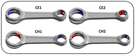
Figure 11.
CE1 and CE2 represent load cases 1 and 2 on connecting rod end. Blue is a hinge. Red is the force, applied as uniformly distributed on the area with the direction according parallel to connecting rod axis, the value and sign according to the calculation and reference system. CH1 and CH2 are the load cases to study the connecting rod head.
After the modifications to the geometry to decrease the mass of the component, new simulations were performed to ensure fatigue life of the connecting rod. As can be observed in Figure 12, the minimum number of fatigue life cycles is not particularly high. However, considering that the simulated load case is the worst possible and that the connecting rod never experienced such a continuous fatigue cycle in real life, the modified connecting rod (result of a series of lightening iterations) is considered safe against fatigue. The next step then involved the fabrication of the component.
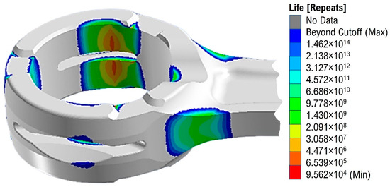
Figure 12.
Results of fatigue analysis performed on the modified version of the connecting rod head.
The new connecting rod was manufactured and compared with the original one. Weight represents the variable of greatest interest. The reverse engineering process combined with finite element calculation allowed it to go from 110 g to 97.6 g, a reduction of 11.2%, as shown in Figure 13.
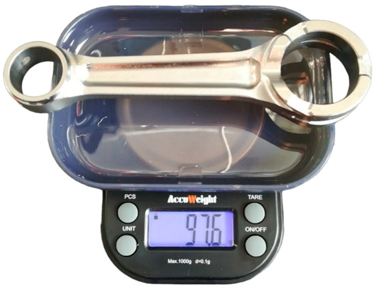
Figure 13.
Weight of the modified connecting rod.
The new prototype is shown in Figure 14.
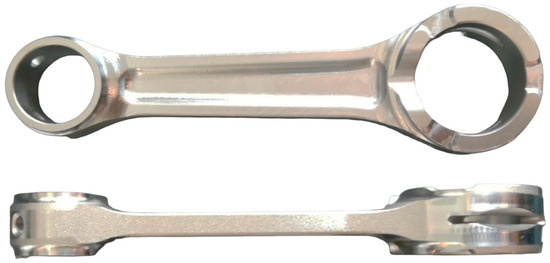
Figure 14.
Two perspectives on the physical prototype of the lightened connecting rod.
4. Discussion
Upon analyzing some of the many issues involved in reverse engineer modeling of a component, it is clear that this is not a traditional design. Rather, it is a design based on a statistical approach. The uncertainty that inevitably exists during each step in the process leads to an overall error that is not easily quantifiable but equally minimizable with the aid of good design practices. An initial error on the component chosen for reverse engineering is inevitable. Surface defects due to inaccuracies incurred during machining, wear of the component related to its poor state of storage, and the presence of surface dirt induce an error that does not depend on the process in reverse. Subsequently, the resolution of a laser scanner, although high, does not cancel an error related to scanning. The presence of shiny and highly reflective surfaces increases the value of this error. An modeling error, on the other hand, is the result of a series of carelessness on the part of the modeler. Uncaptured or disregarded symmetries, misalignments between scans, and failure to correct normal planes or axes of reference of the component increase its overall value. When considering the remanufacturing of the component an error adds to the overall error.
5. Conclusions
The reverse engineering process applied in the context of precision reconstruction and accurate post-machining of mechanical components is particularly challenging. This task is affected by a high degree of complexity due to the numerous steps required. This is emphasized when the logic of reverse engineering is used to make modifications to an existing part of which the original CAD model is not available and whose post-machining final tolerances are extremely high and demanding.
When this tolerance requirement must be met, the main objective is to minimize the overall error to which the process is subjected. This is possible only by reducing the error at each step. The use of a high-precision FARO laser scanner made it possible to derive a high-quality mesh, virtually free of imperfection, useful as a reference for reconstructing the geometry of the connecting rod.
The right approach to CAD remodeling made it possible to minimize the global error found at the end of the process. In this case, the deviation between mesh and reconstructed CAD model must be reduced. This error leads to obtaining a geometry that is only apparently the same as the starting geometry and often satisfies the naive designer. The final result validated the procedure performed and can be applied in different case studies.
Author Contributions
Conceptualization, P.F. and M.F.; data curation, G.A.; formal analysis, M.F. and G.A.; investigation, P.F.; methodology, P.F.; project administration, A.L. and P.F.; software, M.F.; supervision, A.L. and P.F.; validation, A.L.; visualization, A.L. and G.A.; writing—original draft, P.F. and M.F.; writing—review and editing, M.F. and G.A. All authors have read and agreed to the published version of the manuscript.
Funding
This research received no external funding.
Data Availability Statement
Not applicable.
Conflicts of Interest
The authors declare no conflict of interest.
References
- Rekoff, M.G. On Reverse Engineering. IEEE Trans. Syst. Man. Cybern. 1985, SMC-15, 244–252. [Google Scholar] [CrossRef]
- Miiller, H.A.; Jahnke, J.H.; Smith, D.B.; Storey, M.A.; Tilley, S.R.; Wong, K. Reverse engineering: A roadmap. In Proceedings of the Conference on the Future of Software Engineering, ICSE 2000, Limerick, Ireland, 4–11 June 2000; pp. 47–60. [Google Scholar] [CrossRef]
- Ginting, R.; Ishak, A.; Fauzi Malik, A.; Satrio, M.R. Product Development with Quality Function Deployment (QFD): A Literature Review. IOP Conf. Ser. Mater. Sci. Eng. 2020, 1003, 012022. [Google Scholar] [CrossRef]
- Frizziero, L. A coffee machine design project through innovative methods: QFD, value analysis and design for assembly. ARPN J. Eng. Appl. Sci. 2014, 9, 1134–1139. [Google Scholar]
- Liverani, A.; Caligiana, G.; Frizziero, L.; Francia, D.; Donnici, G.; Dhaimini, K. Design for Six Sigma (DFSS) for additive manufacturing applied to an innovative multifunctional fan. Int. J. Interact. Des. Manuf. 2019, 13, 309–330. [Google Scholar] [CrossRef]
- Francia, D.; Donnici, G.; Ricciardelli, G.M.; Santi, G.M. Design for six sigma (DFSS) applied to a new E-segment sedan. Sustainability 2020, 12, 787. [Google Scholar] [CrossRef]
- Frizziero, L.; Donnici, G.; Francia, D.; Caligiana, G.; Gaddoni, A. Stylistic design engineering (SDE) for an innovative green vehicle following QFD and triz applications. Int. J. Mech. Prod. Eng. Res. Dev. 2019, 9, 805–827. [Google Scholar] [CrossRef]
- Donnici, G.; Frizziero, L.; Francia, D.; Liverani, A.; Caligiana, G. TRIZ method for innovation applied to an hoverboard. Cogent. Eng. 2018, 5, 1524537. [Google Scholar] [CrossRef]
- Frizziero, L.; Donnici, G.; Liverani, A.; Santi, G.M.; Bolzani, D.; Golinelli, L.; Marchi, F. Design for six sigma (DFSS) and industrial design structure (IDeS) for a new urban sustainable mobility. In Proceedings of the International Conference on Industrial Engineering and Operations Management, Manila, Philippines, 7–9 March 2021; pp. 1268–1281. [Google Scholar]
- Day, G.S. The Product Life Cycle: Analysis and Applications Issues. J. Mark. 2018, 45, 60–67. [Google Scholar] [CrossRef]
- Mullor-Sebastián, A. The Product Life Cycle Theory: Empirical Evidence. J. Int. Bus. Stud. 1983, 14, 95–105. [Google Scholar] [CrossRef]
- Várady, T.; Martin, R.R.; Cox, J. Reverse engineering of geometric models—An introduction. CAD Comput. Aided Des. 1997, 29, 255–268. [Google Scholar] [CrossRef]
- Várady, T.; Martin, R.R.; Cox, J. Off-line view planning for the inspection of mechanical parts. Int. J. Interact. Des. Manuf. IJIDeM 2013, 7, 1–12. [Google Scholar] [CrossRef]
- Buonamici, F.; Carfagni, M.; Furferi, R.; Governi, L.; Lapini, A.; Volpe, Y. Reverse engineering of mechanical parts: A template-based approach. J. Comput. Des. Eng. 2018, 5, 145–159. [Google Scholar] [CrossRef]
- Buonamici, F.; Carfagni, M. Reverse engineering of mechanical parts: A brief overview of existing approaches and possible new strategies. In Proceedings of the ASME Design Engineering Technical Conference 2016, Charlotte, NC, USA, 21–24 August 2016; Volume 1B-2016. [Google Scholar] [CrossRef]
- Chang, K.-H.; Chen, C. 3D shape engineering and design parameterization. Comput. Aided Des. Appl. 2011, 8, 681–692. [Google Scholar] [CrossRef]
- Anwer, N.; Mathieu, L. From reverse engineering to shape engineering in mechanical design. CIRP Ann. Manuf. Technol. 2016, 65, 165–168. [Google Scholar] [CrossRef]
- Helle, R.H.; Lemu, H.G. A case study on use of 3D scanning for reverse engineering and quality control. Mater. Today Proc. 2021, 45, 5255–5262. [Google Scholar] [CrossRef]
- Zong, Y.; Liang, J.; Pai, W.; Ye, M.; Ren, M.; Zhao, J.; Tang, Z.; Zhang, J. A high-efficiency and high-precision automatic 3D scanning system for industrial parts based on a scanning path planning algorithm. Opt. Lasers Eng. 2022, 158, 107176. [Google Scholar] [CrossRef]
- Campana, F.; Germani, M. Computer-Aided Design and Applications Datum Identification for Tolerances Control on Dense Clouds of Points. Comput. Aided Des. Appl. 2008, 5, 209–219. [Google Scholar] [CrossRef]
- Erdős, G.; Nakano, T.; Váncza, J. Adapting CAD models of complex engineering objects to measured point cloud data. CIRP Ann. Manuf. Technol. 2014, 63, 157–160. [Google Scholar] [CrossRef]
- Bosché, F. Automated recognition of 3D CAD model objects in laser scans and calculation of as-built dimensions for dimensional compliance control in construction. Adv. Eng. Inform. 2010, 24, 107–118. [Google Scholar] [CrossRef]
- Durupt, A.; Remy, S.; Ducellier, G.; Eynard, B. From a 3D point cloud to an engineering CAD model: A knowledge-product- based approach for reverse engineering. Virtual Phys. Prototyp. 2008, 3, 51–59. [Google Scholar] [CrossRef]
- Gauthier, S.; Subsol, G.; Bénière, R.; Puech, W. CAD-driven analysis and beautification of reverse engineered geometric models. Int. J. Interact. Des. Manuf. 2020, 14, 1211–1226. [Google Scholar] [CrossRef]
- Amaral, N.; Rencis, J.J.; Rong, Y.; Amaral V-Engine Manufacturing Engineering. Development of a finite element analysis tool for fixture design integrity verification and optimization. Int. J. Adv. Manuf. Technol. 2004, 25, 409–419. [Google Scholar] [CrossRef]
- Strozzi, A. Costruzione di Macchine; Pitagora: Bologna, Italy, 1998. [Google Scholar]
Disclaimer/Publisher’s Note: The statements, opinions and data contained in all publications are solely those of the individual author(s) and contributor(s) and not of MDPI and/or the editor(s). MDPI and/or the editor(s) disclaim responsibility for any injury to people or property resulting from any ideas, methods, instructions or products referred to in the content. |
© 2023 by the authors. Licensee MDPI, Basel, Switzerland. This article is an open access article distributed under the terms and conditions of the Creative Commons Attribution (CC BY) license (https://creativecommons.org/licenses/by/4.0/).