Article

Heat Flow and Thermal Stress Analysis to Enhance the Temperature Distribution and Service Life of Stone Grill Plates in Barbecue Ovens

1
Department of Aeronautical Engineering, Chaoyang University of Technology, Taichung 413, Taiwan
2
Department of Mechanical Engineering, Lungwa University of Science and Technology, Taoyuan 333, Taiwan
*
Author to whom correspondence should be addressed.
Inventions 2022, 7(4), 103; https://doi.org/10.3390/inventions7040103
Submission received: 29 September 2022 / Revised: 5 November 2022 / Accepted: 9 November 2022 / Published: 15 November 2022
(This article belongs to the Special Issue Low-Cost Inventions and Patents: Series II)

Abstract

:
The causes of the fracturing of stone grills in barbecue ovens were analyzed using a coupled analysis model that combined combustion thermodynamics with heat conduction and the finite element method. The proportion of mixed air for combustion was simulated, and the stone grill plate temperature and thermal stress distribution were the two factors taken to enhance the design of stone grill plates. Moreover, thermal images were used to compare the performance of the original and the improved plates to quantify the improvements, and validate the accuracy of the simulations. The results showed that the temperature distribution was uniform across the stone grill plate. When comparing the simulation model and the actual experiment, the simulation model can generate an optimal design with fewer errors in a shorter period. The combustion tube is deemed to have considerable influence on the performance of the barbecue oven. The surface temperature distribution of the stone grill plate was improved by controlling the amount of fuel entering the combustion system and/or changing the material and shape of the stone grill. On the other hand, the analysis results of the improved stone grill plate in this study showed that we can correct the temperature difference and thermal stress difference caused by the opening of the upper cover of the oven. According to our study, the average thermal stress on the surface of the stone grill plate was effectively reduced by 45.3 MPa. The average temperature difference decreased by 91 °C. At the same time, by improving the intake position and method of the combustion tube, the air mass flow in the combustion tube increased by 12%, which effectively improved the combustion efficiency of the combustion tube. In particular, a more uniform distribution was achieved by decreasing the temperature of the mixed air entering the combustion tube, which in turn increased the flow rate and velocity of the air flowing through the top of the flame to the bottom surface of the stone grill plate. The strategies employed can prevent the thermal-stress-induced fracturing of stone grill plates and prolong their service life.

1. Introduction

Modern high-end grills are available in various styles and sizes, and can thus handle a broad range of applications [1]. Grilling has emerged as a commonly used home-cooking method. To achieve a perfect grilled flavor and consistent food quality, the user must accurately adjust the combustion conditions and temperature distribution. Moreover, a suitable grill with controllable grilling settings must be used [2,3]. Consequently, the development of high-end barbecue grills has emerged as a research hotspot in recent years [4,5,6,7,8,9,10].
With such research, innovative heating methods for barbecue grills [11] such as infrared heating, have been introduced in addition to the use of traditional fuels. Through such methods, users can precisely control the cooking process for different ingredients. Nevertheless, there remains room to improve conventional grills, especially in terms of controlling the surface temperature of the grill plate to ensure a uniform temperature distribution [3,12,13].
In recent years, outdoor barbecue has emerged as not only a method to prepare food, but also a popular mode of socialization [14,15,16,17,18,19]. The corresponding grills have evolved over time, and various fuel systems such as charcoal, natural gas, and propane, have been introduced to address different requirements [15,20].
Although combustion systems may have different types of energy sources, the most economical and convenient fuel systems correspond to compressed gases or liquids. The combustion system considered in this study uses propane and natural gas, which represent efficient fuel sources. Propane fuel, which is prevalent in the market, is commonly stored in pressurized tanks and available in liquid form with various weight percentages.
The process of cooking food by burning gas fuel typically involves three heat transfer modes: (1) Heat convection: The working fluid (e.g., air) around the food is heated, which then transfers energy to the food [21]. (2) Heat conduction: An intermediate heating material, such as a heating pan, is heated and placed in direct contact with the food to transfer energy to the food [22]. (3) Heat radiation: Many existing ovens use infrared (IR) burners to generate heat in the form of infrared rays, which deeply penetrate the surface of the food during cooking, allowing users to produce restaurant-quality barbecue food [23].
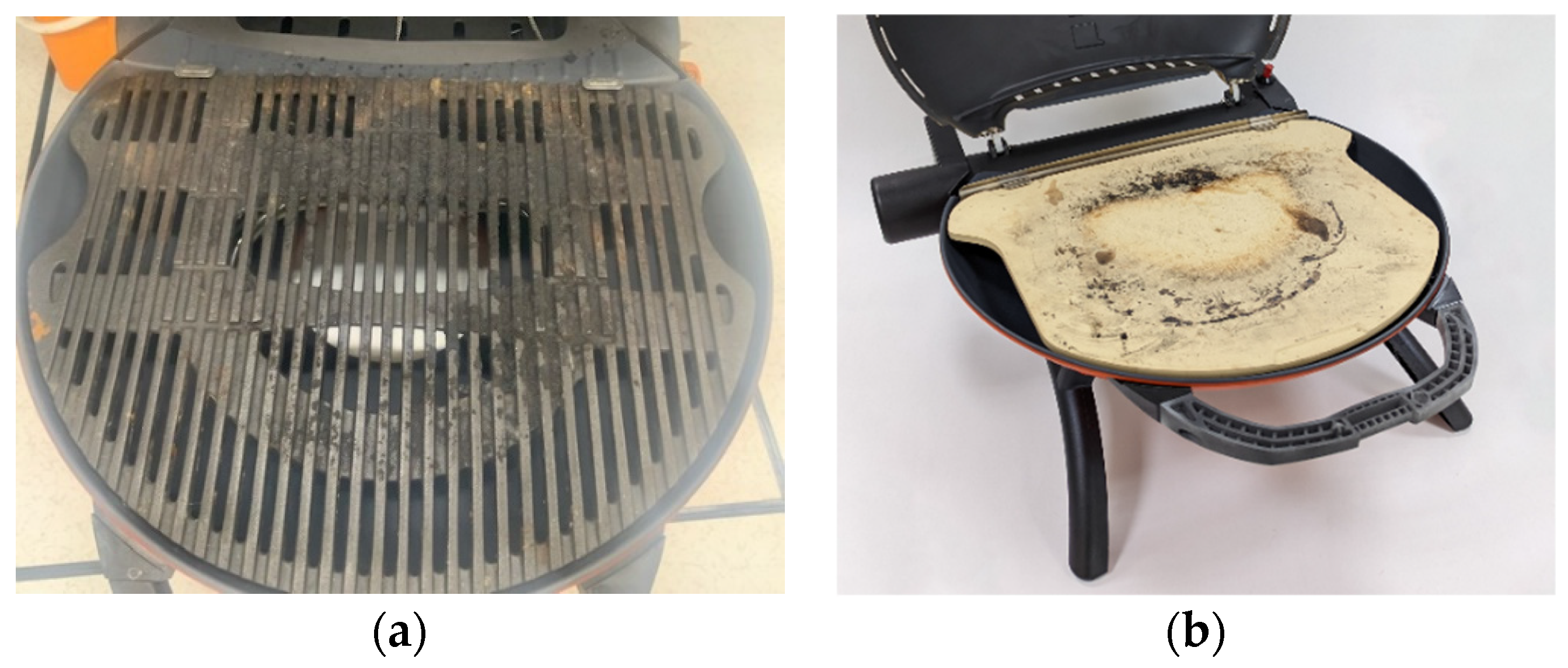
The objective of this study was to optimize grill systems that use natural gas and propane fuels. The original design involves an iron grill pan with multiple gaps, as shown in Figure 1a. Owing to the excellent heat transfer characteristics of the iron plate, the grid-like pores promote air convection, which can alleviate the problems associated with combustion and uneven temperature. However, iron pans are not suitable for processing several foods, such as pizza. In such instances, stone grill plates must be used. Nevertheless, stone grill plates come with their own set of problems: First, stone grill plates are prone to fracturing, as shown in Figure 1b. Second, the combustion temperature is more uneven than that of iron plates, which may generate defects in the product. Therefore, the reasons for the fracturing of stone grill plates and uneven combustion temperatures must be investigated.
Because the combustion system and furnace structure are typically mass-produced, the product cannot be significantly modified. Therefore, optimization techniques must be used, for instance, to enhance the uniformity of the temperature distribution on the plate surface, reduce the thermal stress, and prevent breakage during use. Moreover, it is desirable to modify the product such that the manufacturing and overall cost are not significantly affected. Notably, the stress and temperature distribution of a stone grill plate cannot be visually evaluated. Other methods must be used to clarify the influence of the design of the burner tubes and heat transfer characteristics on the temperature and thermal stress across the grill surface.
Therefore, in this study, a number of simulations were performed to predict the temperature and thermal stress of bakeware, and to analyze the thermal stress model by combining a computational fluid dynamics-based combustion flow model [24,25,26,27] and heat conduction, as well as the finite element method. The temperature and thermal stress distribution of the grill plate were determined by simulating the combustion of mixed gas and heat conduction, and then the two factors were taken to optimize the barbecue design. In addition, a thermal imager was used to collect temperature data to verify the consistency of the actual and analytical models [28,29,30]. The optimized design was then created to exhibit a more uniform temperature distribution pattern than the original design [31,32].
Many scholars improve a problem in one way, but often a non-optimal design results. The breakthrough approach of this study is that it not only improves the design of the stone grill plate, but also improves the air intake design of the fuel line. In such a way, problems such as the cracking of the stone grill plate caused by the temperature difference and thermal stress difference caused by the opening of the upper cover of the oven can be solved all at once.

2. Materials and Methods

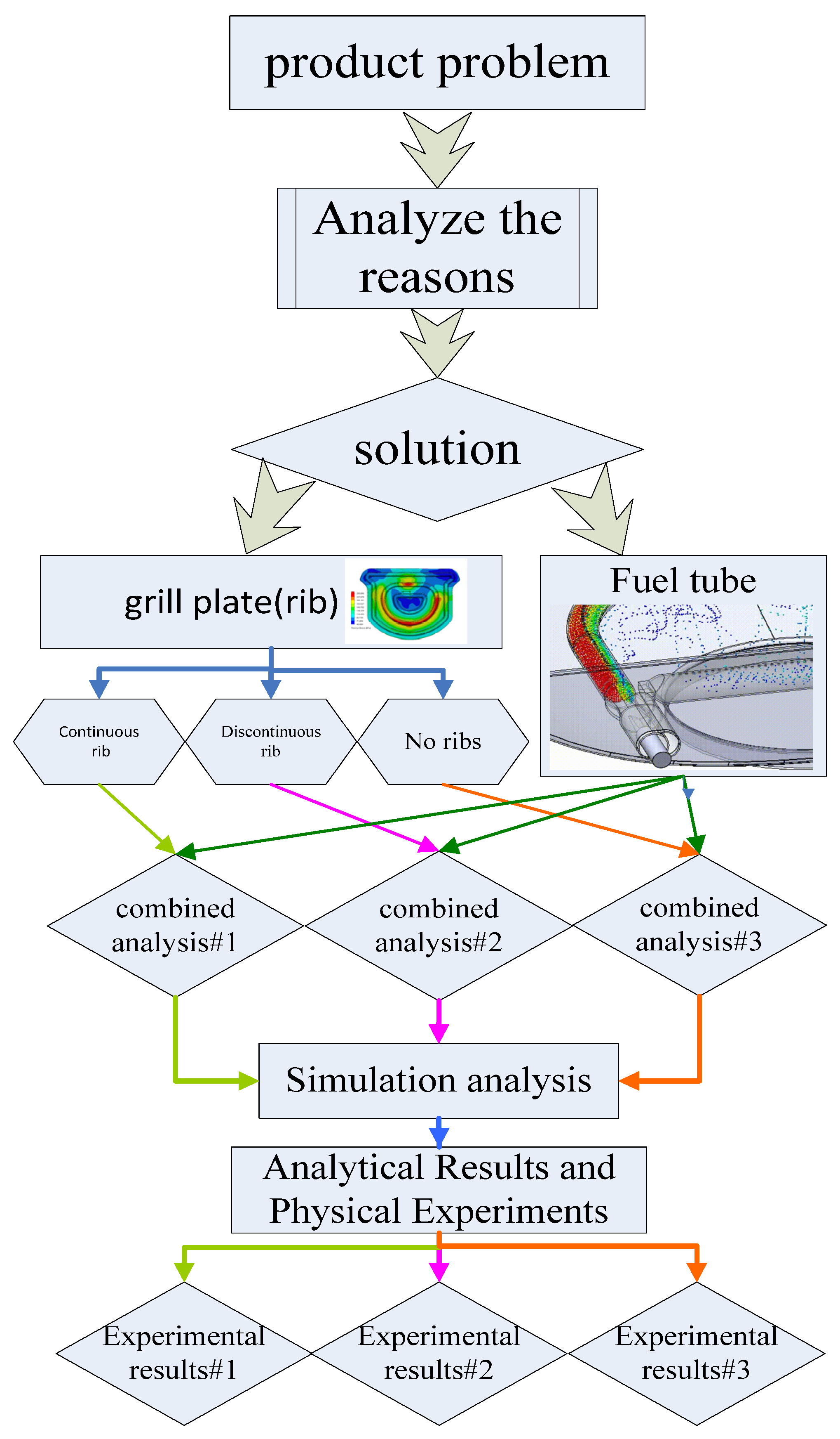
As mentioned, the objective of this study is to explore the reasons for the fracture of stone grill plates during use, and to enhance the design of the fuel tube and the overall performance of plate and grill. To this end, Ansys CFX simulation analyses were performed, as illustrated in Figure 2.
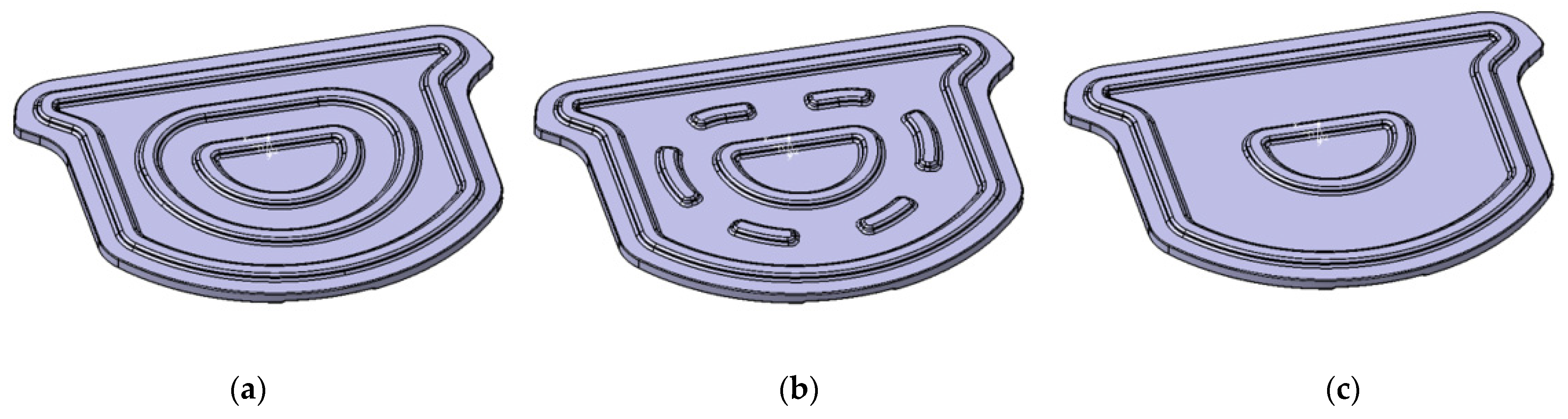
The first step was to clarify the causes of the failure of the stone grill plate and identify a solution. The primary purpose is to theoretically analyze the problems associated with the existing barbecue grill system, and identify solutions to alleviate the uneven temperature distribution and thermal stress on the grill surface. The second step was to examine the fuel tube design. In the third step, three stone grill plate designs were created to evaluate the failure characteristics and develop the optimal design.
At the same time, flamelet and k-Epsilon turbulence models were used in the oven combustion and flow field physics model. The stone grill plate’s heat conduction method was also taken into consideration to simulate the steady-state temperature distribution. The inlet and outlet boundary conditions of the oven chamber were set at 101,325 Pa, and the ambient temperature set at 25 °C. The coordinates were placed in the center of the stone grill plate, and a small area in the center was designated as a fixed boundary so that the stone grill plate can generate thermal expansion. With that, thermal stress could be calculated.
Fourthly, a cross-simulation analysis of the designed fuel tube and stone grill plate was performed. Additionally, an analysis system was established for the oven, measurement, and the testing equipment. Several suggestions were deduced for improving the scientific design process and solving the problems of the similar oven systems. Finally, after validating the stone grill plate and corresponding outputs, the optimal design was developed based on the simulation analysis and verification results.

2.1. Equipment

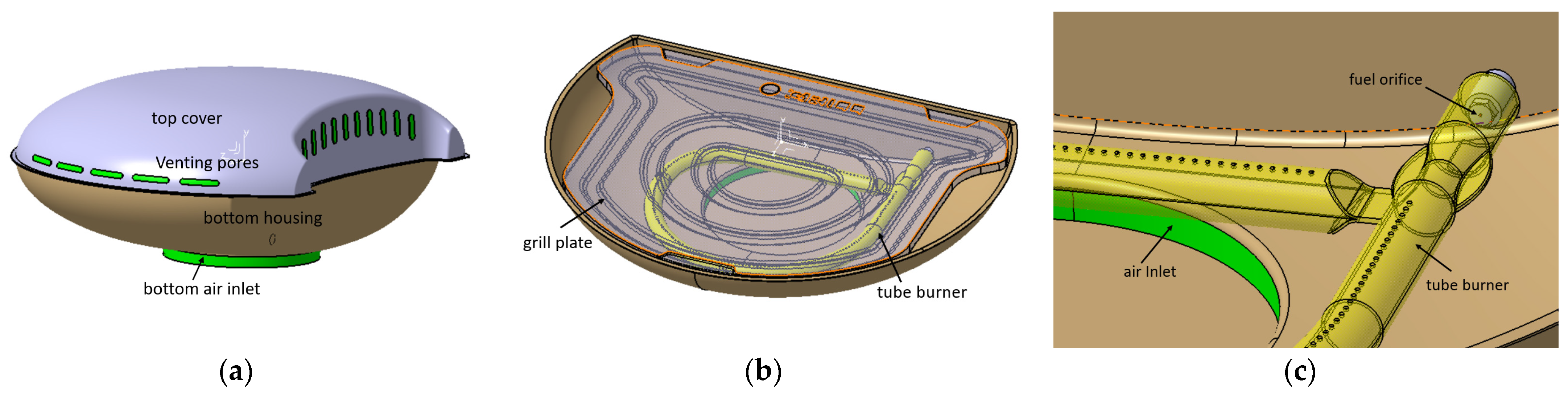
The grill structure includes a top cover, bottom housing, grill plate, tube burner, and fuel orifice, as shown in Figure 3. The top cover has venting pores to provide combustion heat, and the exhaust gas can flow out of the oven cavity when the cover is in use. The bottom housing includes an oil collecting pan and a base cover to form a gap to provide the air required for combustion (in the bottom air inlet).

2.1.1. Model Analysis

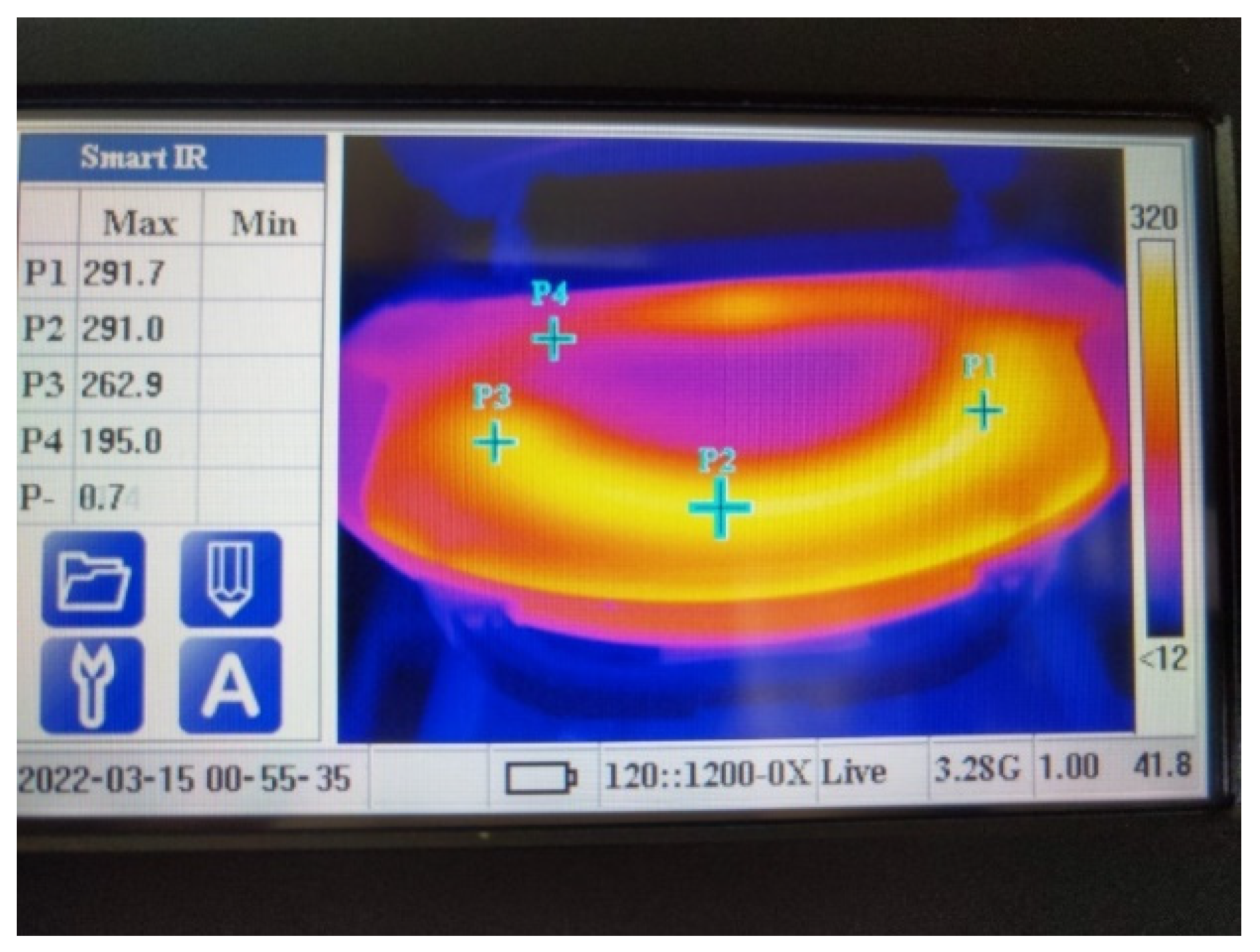
Because the test stone grill plate typically fractures when the grill is opened for grilling, it can be assumed that when the top cover is opened, the convection of the cold air above the surface of the grill plate is intensified, resulting in a rapid temperature decrease over the pan surface. In contrast, continuous heating occurs due to the flame of the bottom combustion tube. These phenomena generate a significant temperature difference and thermal stress. At the point of opening the grill, the thermal images recorded by the thermal imager are consistent with those of the analysis model. Therefore, the image corresponding to the point at which the lid is opened is examined to analyze the stress distribution of the grill plate.

2.1.2. Boundary Conditions

The thermal power specification of the barbecue oven is 10,500 BTU/h. In the combustion simulation, the temperature is less than 25 °C, and the measured oven propane flow rate is 220 g/h, set as the boundary condition of the orifice. Gas (propane) enters the gas mixture combustion tube through the nozzle, and the gas mixture combustion tube is designed based on the Venturi principle. Specifically, ambient air is sucked into the mixed combustion tube, and it flows out through the multiple holes in the mixed combustion tube. When combustion is initiated, the control gas valve is opened, allowing the gas to pass through the gas mixture pipe for the first gas mixing. The ignition device set above the air–fuel mixture combustion hole ignites the gas.
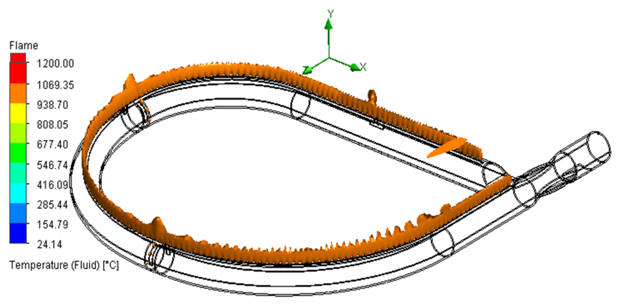
In the first mixing process, the amount of air required for complete combustion is typically inadequate. Therefore, the gas flows outside the air-fuel mixture combustion tube from the combustion hole. At the same time, the ambient air undergoes the second aeration process to enable complete combustion. The design of such combustion tubes is relatively mature. In general, various specifications are available when designing a barbecue, and thus, no redesign is required, as shown in Figure 4.
Moreover, the combustion system and furnace structure to be improved are typically mass-produced and must be suitable for various iron grill pans. Therefore, the modification of the furnace body and combustion tube design is highly restricted. Considering these aspects, limited modification and simulation analyses were performed in this study based on furnace body specifications. Table 1 presents the material specifications of the stone grill plate considered to establish the analysis model.
On the other hand, the Finite Volume Method analysis grid used 0.8 cm tetrahedron elements, while the square size of the combustion tube grid was refined to 0.1 cm each to guarantee the analytical model convergency. For the stone grill plate, Finite Element analysis grid with a tetrahedron element of 0.8 cm each was adopted, but the square size of the grid in the heating area on the bottom surface of the stone grill plate was refined to 0.2 cm. The total number of squares in the grids was about 2.9 million, the flow field was 1.7 million, and the stone grill plate was 1.2 million. The same setting and same method to increase the density were applied in the different designs of the grid density analyses. The same setting and benchmark would facilitate our analysis of the differences among the testing models. Grid distribution and grid independency are shown in Table 2.

2.2. Mathematical Model

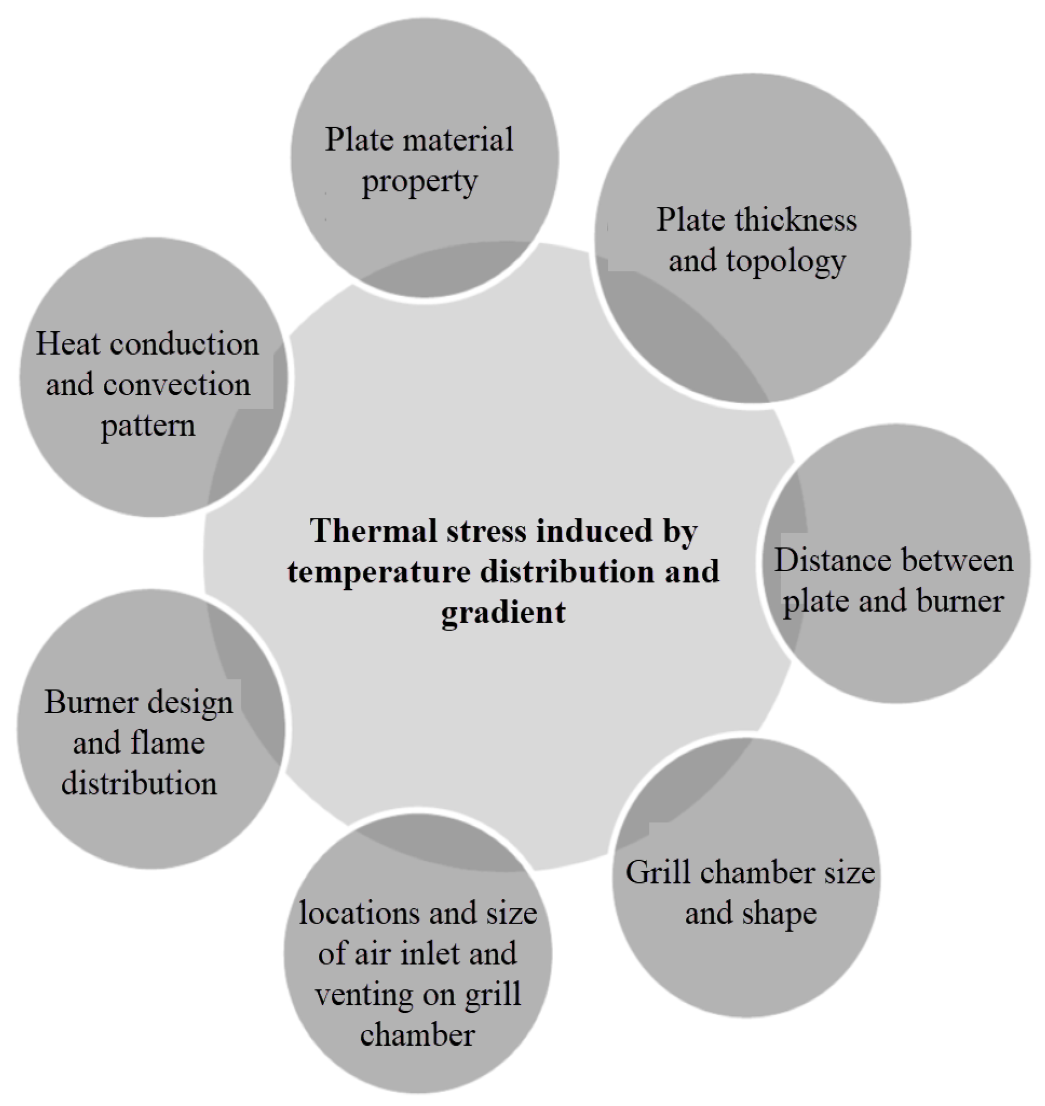
As the stone grill plate rupture is caused by excessive thermal stress, it is also true that thermal stress is affected by many parameters. Under the existing configuration and constraints, this study proposes a new set of design parameters, including the position and method of air intake in the combustion tube, to improve the air/fuel ratio and average flame distribution of the combustion tube after conducting analyses and experiments. At the same time, the shape of the structural ribs at the bottom of the stone grill plate was modified to reduce local high temperature and thermal stress concentration. The design parameters of the stone grill plate and the combustion tube work together in a way that they not only affect the flame distribution state during combustion, but also have a direct heating impact on the stone grill plate, and the distribution of thermal stress.
A RANS-based approach with the k-ε model was selected to further exemplify this case [33]. The continuity and momentum equations in RANS format were introduced as shown in Equations (1) and (2):
ρ t + x i ( ρ u i ) = 0
t i ( ρ u i ) + x i ( ρ u i u j ) = p x i + x j [ μ ( u i x j + u j x j 2 3 δ i j u l x l ) ] + ρ g + x j ( ρ u i u j ¯ )

2.3. Original Design Analysis Results

The design simulation analysis was divided into two parts, corresponding to the original combustion system and stone grill plate The grill plate was changed from an iron grill plate with gaps to a stone grill plate with no openings on the surface. In actual use, the problem of uneven temperature is quite apparent in such systems.
In the simulation analysis of the combustion air intake, owing to the large shading caused by the stone grill plate, most of the air intake at the bottom air inlet is directed to the bottom of the slate and input to the combustion air mixture pipe, as shown in Figure 5. This configuration leads to several undesirable results. First, the volume flow rate of air sucked by the gas mixing pipe is fixed. If the intake air temperature increases, the air density decreases, and thus, the air mass drawn into the combustion tube per unit time decreases for a given volume flow. In the analysis, the intake air temperature reaches 140 °C. The density decreases compared to that at an intake air temperature of 25 °C, and thus, the air mass drawn into the combustion tube per unit time decreases by 28%. This phenomenon hinders complete combustion. The second result pertains to the air intake method. The system inputs exhaust gas with a high concentration of carbon dioxide, and thus, the oxygen content is reduced.
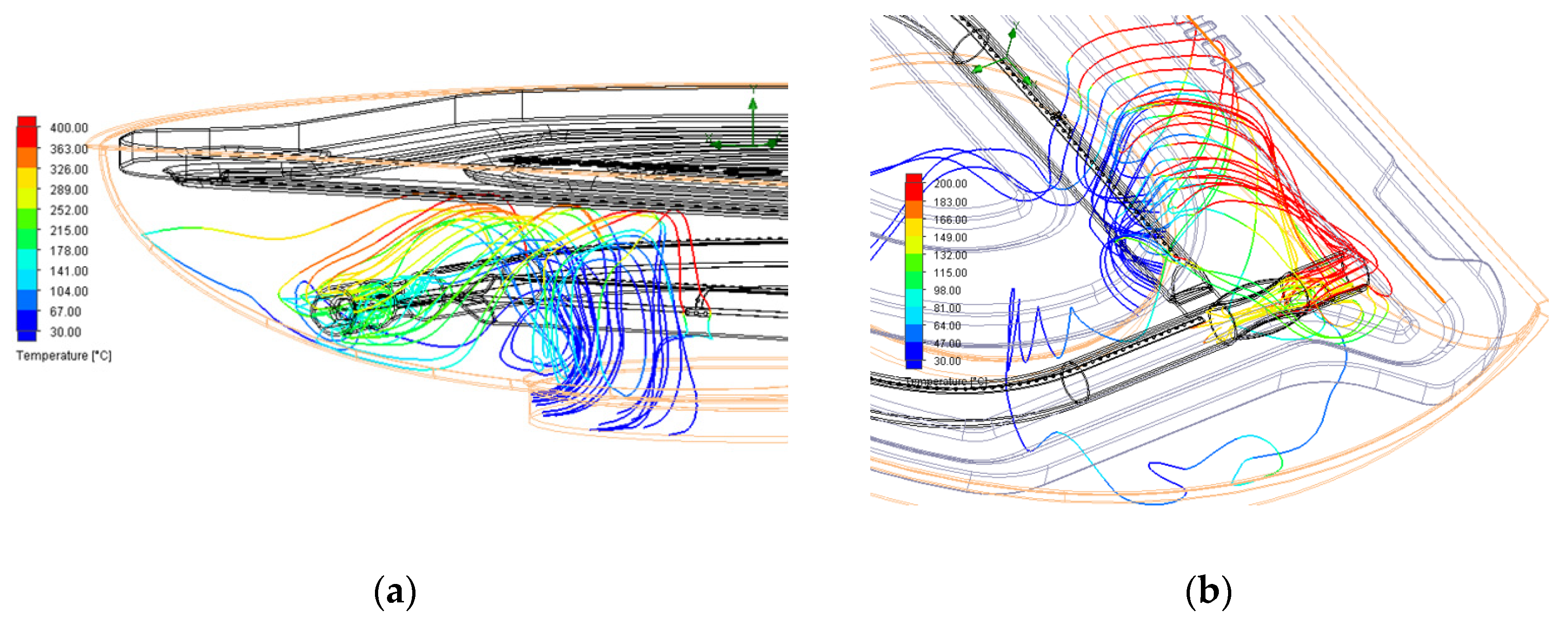
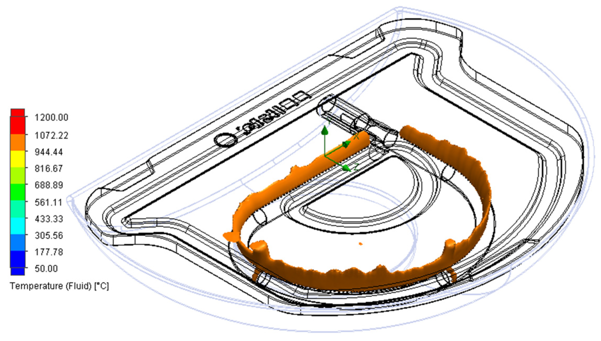
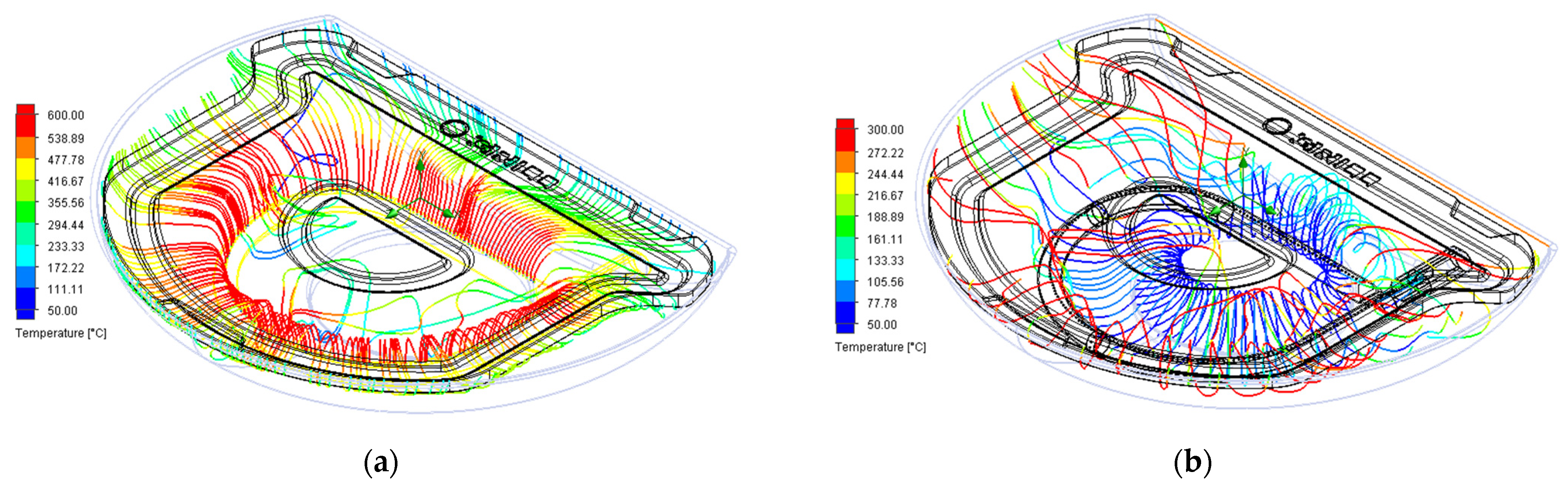
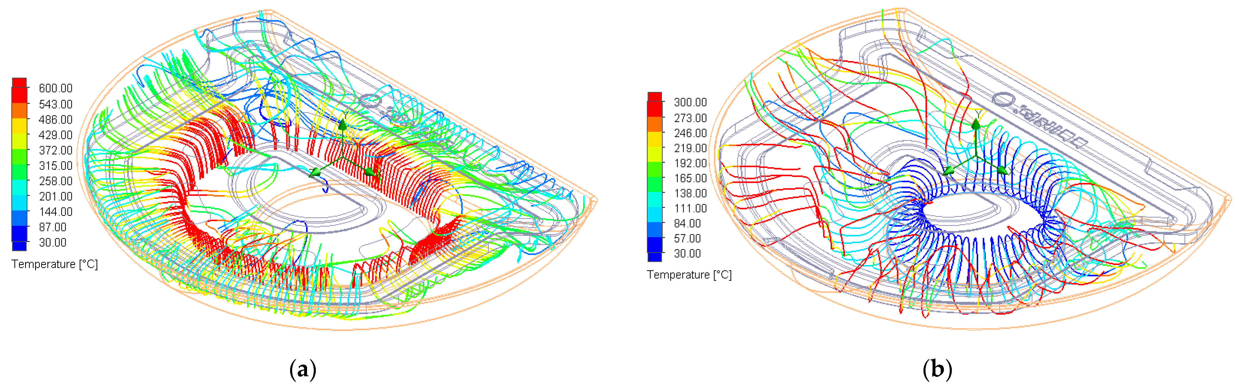
Figure 6a shows the temperature streamlines indicating the burner distribution during the second aeration. After the streamlines flow to the upper part of the concentrated combustion, they flow to the periphery of the stone grill plate. No heat energy is transferred to the middle part of the stone grill plate. This phenomenon generates a large temperature difference between the middle of the stone grill and top of the burner when the top cover is opened. This situation is consistent with that observed in the image recorded by the thermal imager, as shown in Figure 7b. Notably, the intake port streamline distribution shown in Figure 6b indicates that the original design does not produce excessively many abnormal parts. Nevertheless, the air entering the combustion tube mixture does not accumulate at the air mixture intake port.
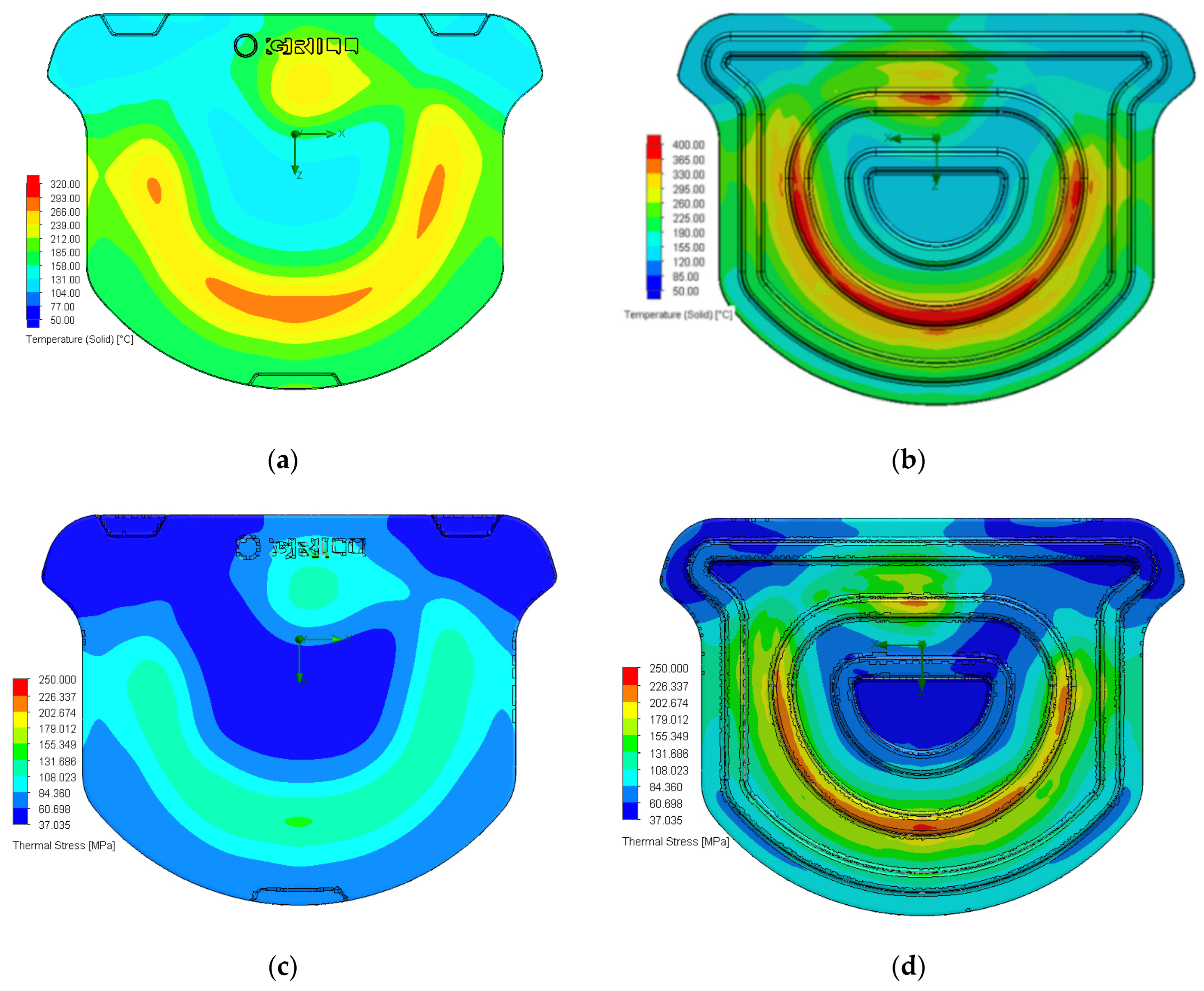
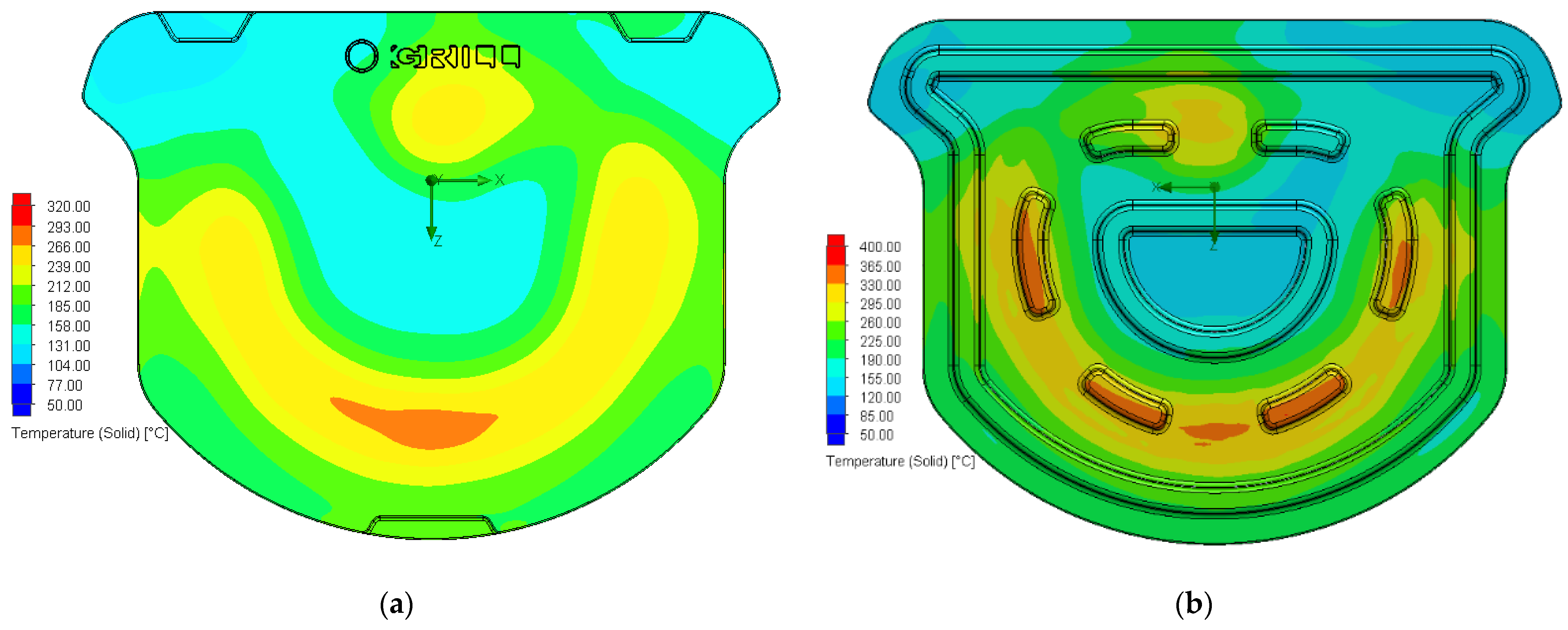
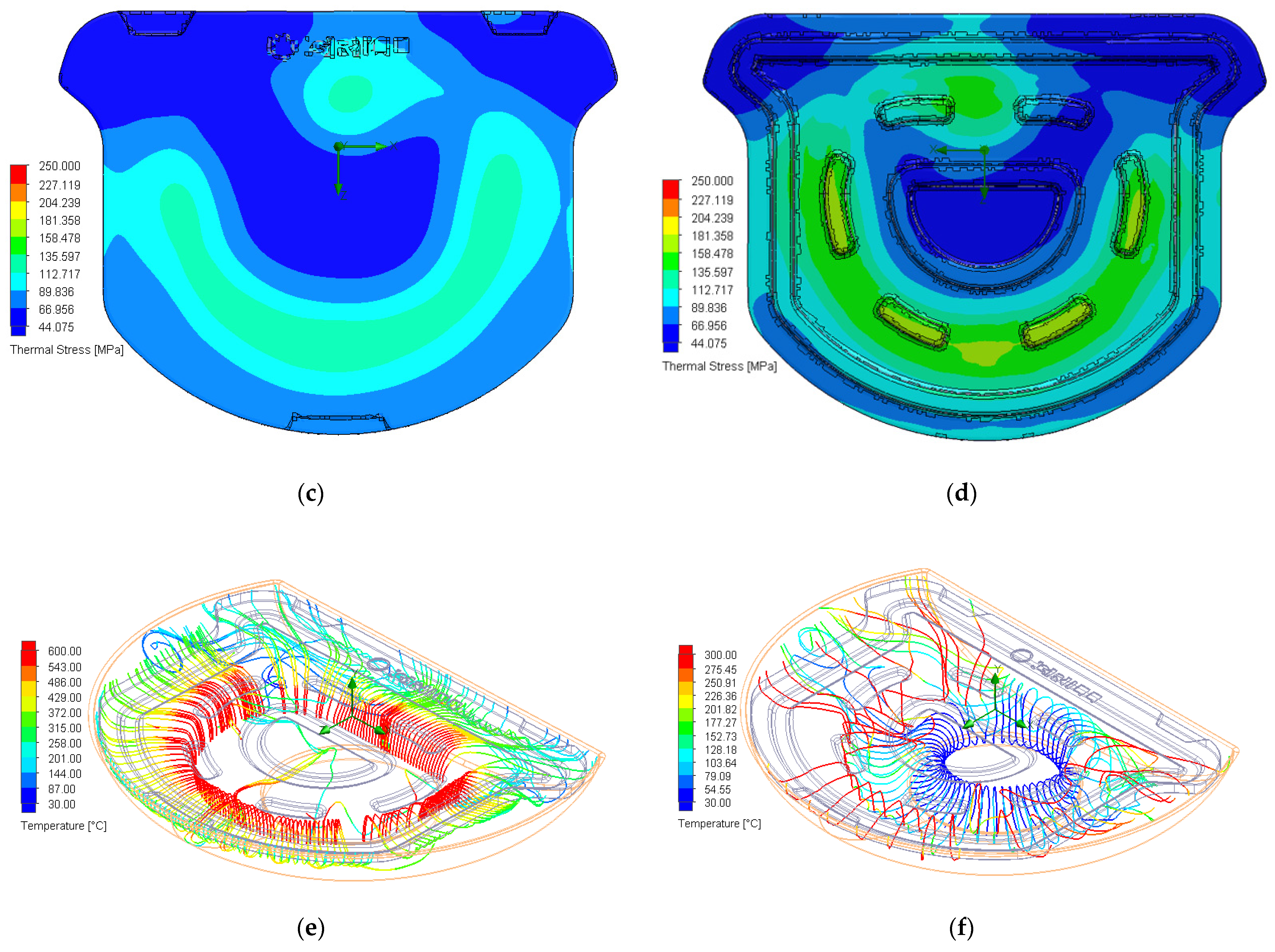
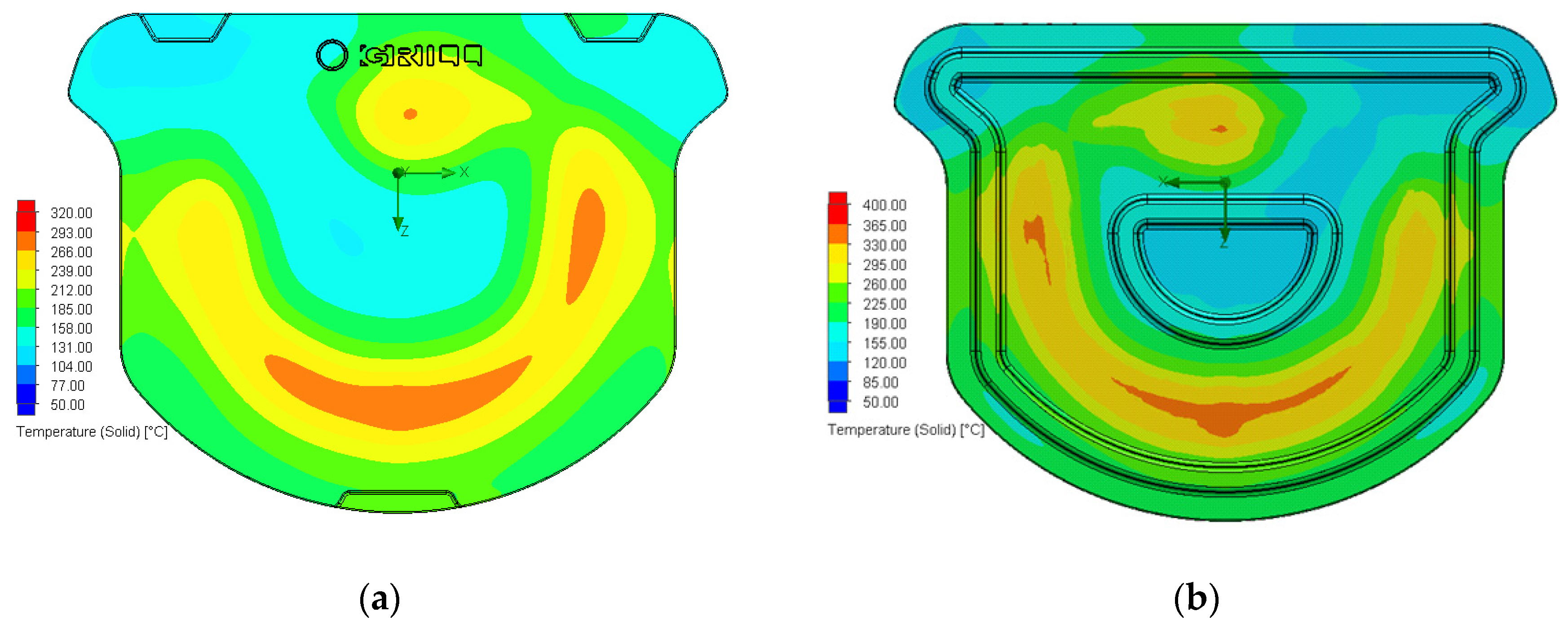
Figure 7 shows the surface temperature of the original grill plate and image recorded by the thermal imager. In Figure 7a, the orange-red part corresponds to a temperature of 266–320 °C, and the highest temperature observed in Figure 7b is approximately 300 °C. The high-temperature regions in Figure 7a,b are similar, and highlight that the area with the highest temperatures pertains to the fuel orifice. 
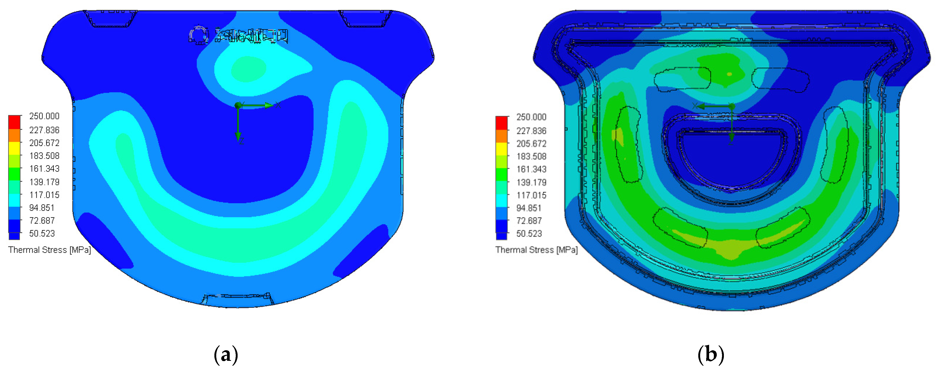
Figure 7c shows that the thermal stress on the surface of the grill pan is concentrated on the combustion pipeline. The maximum and minimum thermal stresses are 160 and 110 MPa, respectively, corresponding to a difference of 50 MPa.
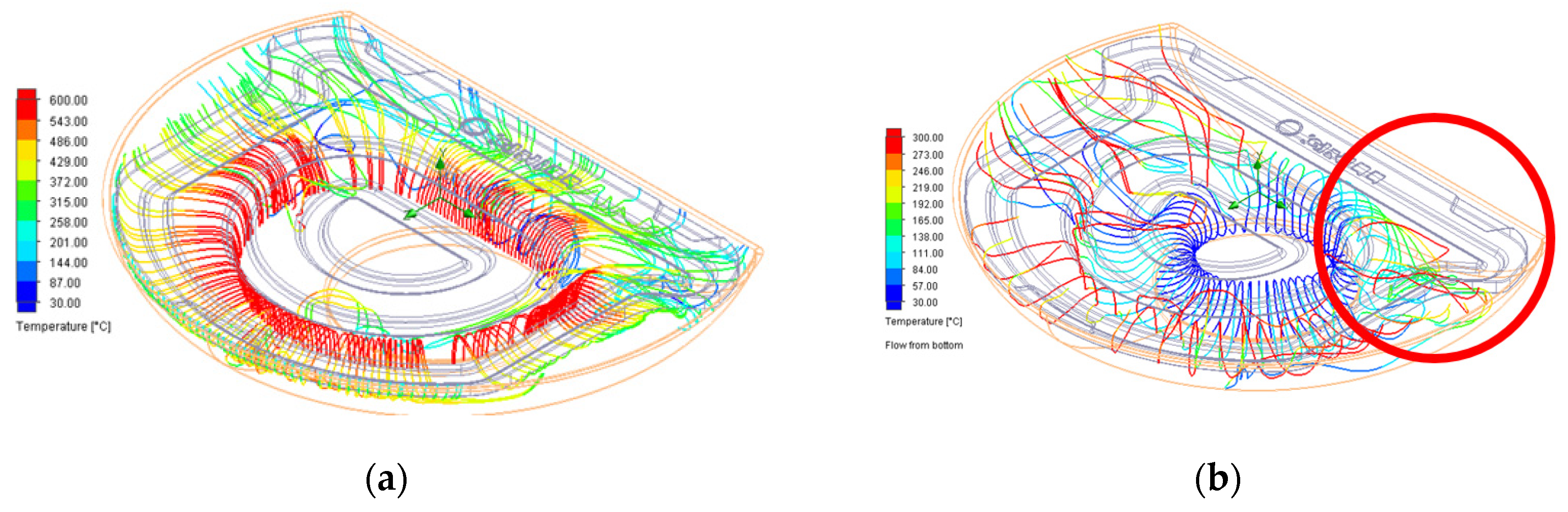
Figure 7d shows the temperature distribution at the bottom of the original grill plate. The maximum temperature is approximately 400 °C, and the distribution is concentrated over the combustion line. 
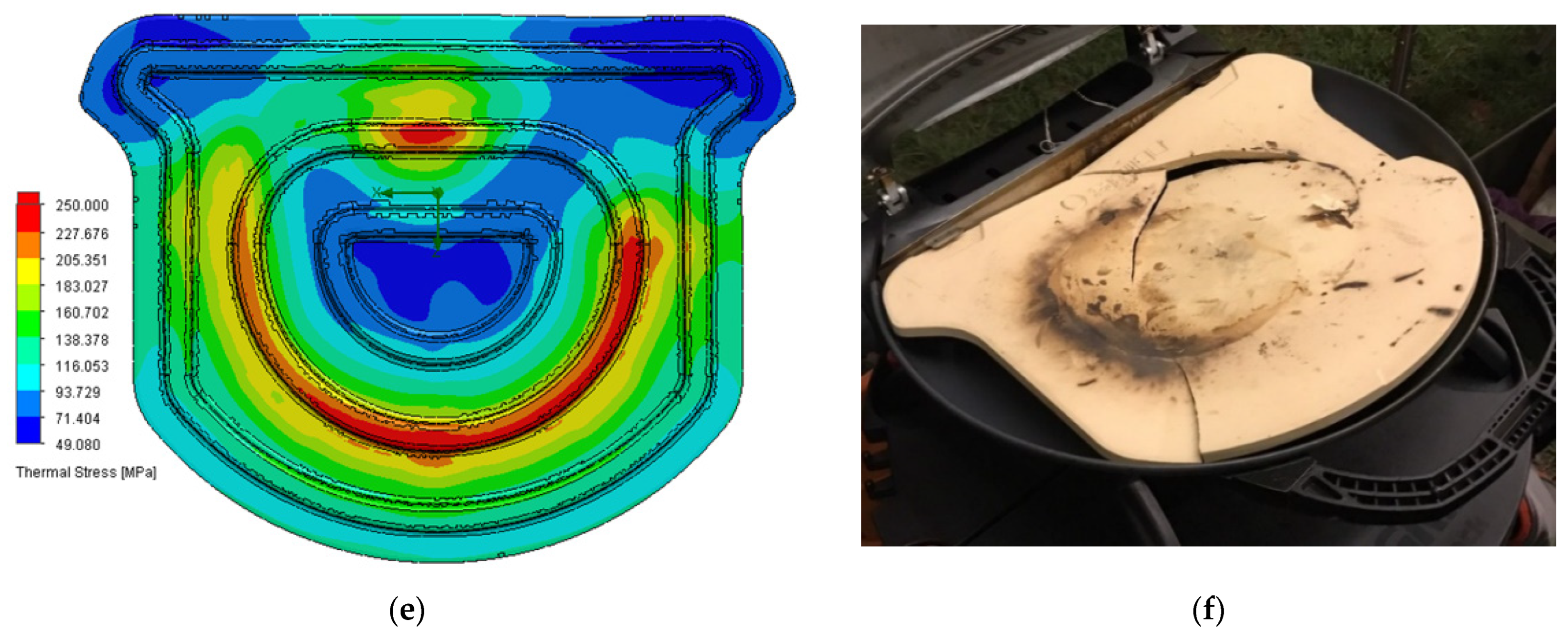
Figure 7e shows the thermal stress distribution at the bottom of the grill plate. The thermal stress is accumulated over the combustion pipeline, and the surface thermal stress is 250 MPa. The difference between this stress and that in the lowest thermal stress region (49 MPa) is approximately 200 MPa. In other words, the high-temperature area is consistent with the fracture area of the solid stone grill plate, and the stone grill plate fractures in the maximum stress area. The corresponding fracture mode can be observed from the thermal stress analysis results, as shown in Figure 7f.

3. Results

3.1. Improved Design #1

Considering the above mentioned findings, three improved designs were prepared. In improved design #1 (CA#1), the intake mode of the combustion air–fuel mixture tube is modified to decrease the temperature and intake of combustion exhaust gas and increase the quality of air entering the mixing tube per unit time. Specifically, the inner side of the furnace wall is connected to a deflector, as shown in Figure 8. The combustion gas mixing tube intakes the ambient air, and the guide plate (through penetration) can balance the internal and external pressures. The objective is to prevent the pressure difference from causing the combustion mixture tube to generate suction port pressure, which can lead to unstable flame conditions.
The combustion system with the modified design is simulated. The results shown in Figure 9 and Figure 10 indicate that the instability of the flame combustion conditions is reduced. When the stone grill plate is installed on the grill (Figure 7a and Figure 11a), the surface temperature distribution on the grill pan indicates that the flame-burning conditions are stable. The high-temperature area is not concentrated at the fuel nozzle outlet. The maximum temperature on the surface of the grill plate decreases from 293–320 °C (red zone) to 266–293 °C (orange zone), corresponding to a difference of 20–30 °C.
The burner streamline distribution after the stone grill installation, shown in Figure 10a, indicates the heat energy concentration area and flow direction. Figure 10b shows that the modified combustion system intakes the air mixture of the combustion tube, which accumulates in the air mixture intake port, and satisfactory results are obtained.
When the modified combustion tube is used, the temperature at the bottom of the stone grill plate is high, and all high-temperature regions are above the combustion tube, corresponding to the continuous rib at the bottom of the stone grill plate. At this location, the maximum temperature is 400 °C (red area). The low-temperature regions have temperatures of approximately 120–155 °C. The temperature difference is as high as 280 °C, as shown in Figure 11b. Moreover, areas with high thermal stresses on the surface of the stone grill plate correspond to the relative positions on the continuous ribs. The maximum thermal stress is approximately 108–155 MPa. The area with high thermal stresses at the bottom of the stone grill plate correspond to the continuous rib, as shown in Figure 11c. The maximum thermal stress is approximately 202–250 MPa, as shown in Figure 11d. Therefore, the thermal stress regions are positively correlated with the high-temperature regions.
Furthermore, we discuss the analysis results of the original stone grill pan. The increase in the burning flame speed rapidly increases the temperature at the surface and bottom of the grill, and the average stress rapidly increases. When the surface and bottom surfaces of the stone grill plate exhibit uniform temperatures, the average pressure decreases.
The flame contact of improved design #1, which is a continuous rib design, is shown in Figure 12a. This design still suffers from uneven thickness and localized stress. Therefore, improved designs #2 and #3 are introduced (Figure 12b,c, respectively) to alleviate the local stresses generated by uneven thickness. In improved design #2, the continuous rib of the original pan is transformed to a discontinuous one. In improved design #3, the continuous ribs are removed.

3.2. Improved Design #2

In this design (CA#2), the continuous rib on the bottom surface of the stone barbecue plate is changed to a discontinuous one to alleviate problems such as stress concentration caused by uneven thickness.
The temperature distribution on the surface of the grill plate of this modified design, shown in Figure 13a, indicates that the high-temperature area is concentrated in the lower middle area, above the combustion tube. The high-temperature areas at the bottom of the stone grill plate are located at the rib positions, as shown in Figure 13b. These locations are above the burner tube, corresponding to the discontinuous rib at the bottom of the stone grill plate. The discontinuous rib at the bottom of the stone grill plate has a maximum temperature of 365 °C (orange area). The minimum temperatures are approximately 120–155 °C. Therefore, the temperature is reduced by 210 °C, as shown in Figure 13b.
Figure 13c shows that the area with high thermal stresses on the surface of the stone grill plate corresponds to the relative position of the combustion tube. The maximum thermal stress is approximately 112–135 MPa. The area with high thermal stress at the bottom of the stone grill plate corresponds to the discontinuous rib location. The maximum thermal stress is approximately 159–181 MPa, as shown in Figure 13d. The difference in the thermal stress is 43–69 MPa. Figure 13 shows that the thermal stress regions are positively correlated with the high-temperature regions. Therefore, to reduce the surface thermal stress, the surface temperature distribution of the stone grill plate must be made more uniform. Figure 13e shows the burner streamline distribution after installing the CA#2 stone grill plate, which indicates the heat energy concentration area and flow direction. Figure 13f shows that after passing through CA#2, the air intake method of the combustion tube mixing air achieves the expected effect.
In other words, in the discontinuous rib design, the surface and bottom temperatures of the grill plate are more uniform owing to the increased burning flame velocity. The local stress phenomenon is effectively alleviated.

3.3. Improved Design #3

In this design (CA#3), the continuous ribs on the bottom surface of the stone grill plate are removed to further reduce the stress concentration caused by uneven thickness.
According to the temperature distribution on the surface of the grill plate, the high-temperature area is concentrated in the lower middle area and fuel nozzle outlet above the combustion tube positions, as shown in Figure 14a. The high-temperature area at the bottom of the stone grill plate appears above the combustion tube, as shown in Figure 14b. Nevertheless, the high-temperature concentration areas on the surface and bottom of the stone grill plate exhibit reduced maximum temperatures of 266–293 °C and 330–365 °C, respectively. The minimum temperatures are 120–155 °C, and the temperature difference decreases to 210 °C, as shown in Figure 14b.
Figure 15 shows that the areas with high thermal stress on the surface of the stone grill appear at the relative positions of the combustion tubes. The maximum thermal stress is approximately 117–139 MPa. In addition, the high thermal stress at the bottom of the stone grill plate appears in locations of the discontinuous ribs. The maximum thermal stress region is approximately 161–183 MPa. The thermal stress is effectively reduced by 41–67 MPa. As shown in Figure 14 and Figure 15, the thermal stress regions are positively correlated with the high-temperature regions. The surface thermal stress distribution in this case is more uniform than that in CA#2.
Thermal imaging detection was performed to verify the temperature distribution of the grill plate, as shown in Figure 16. The results show that the temperature distribution of the grill plate is more uniform in the CA#3 configuration. A comparison of Figure 7b (thermal image of the original stone grill) and Figure 16 (thermal image of the CA#3 stone grill) shows that the surface temperature difference of the stone grill is considerably decreased. The specific values are presented in Table 3. By decreasing the temperature difference, the thermal stress on the surface can be reduced, thereby prolonging the service life of the stone grill plate.
Figure 17a shows the burner streamline distribution after installing the CA#3 stone grill plate, which indicates the heat energy concentration area and flow direction. Figure 17b shows that after passing through the stone grill plate of CA#3, the air intake method of the combustion tube mixing air achieves the expected effect.
Overall, by removing the continuous bottom rib of the pan in the CA#3 configuration, the combustion flame velocity can be increased. The temperatures of the surface and bottom of the grill pan become more uniform than those in the original design. The local thermal stress phenomena are alleviated. The measurement results also confirm that fracturing can be prevented in this configuration.

4. Discussion

In this study, ANSYS CFX analyses were conducted utilizing a coupled analysis model method based on combustion thermodynamics, heat transfer, and finite element methodologies. The objective is to prevent the fracturing or failure of barbecue stone grills. The process flow has been described in Section 2 and Figure 2. The initial goal is to understand the causes of the problem. Our analysis and experiment results indicated that the cracks on stone grilling plates were due to two main reasons. Further thermal imaging results indicated that the heat of the stone grill plate was concentrated at the outlet of the fuel nozzle. Moreover, the temperature difference on the stone grill plate was extremely large and generated local thermal stress, which caused the stone grill plate to crack in the location opposite to the fuel pipe. The second step is to improve the temperature of the mixed air entering the combustion tube to increase the flow rate and velocity of the airflow through the top of the flame to the bottom surface of the stone grill. Additionally, it is necessary to ensure that the temperature of the stone grill plate is maintained at the same level. The third step is to improve the design of the continuous ribs and quantify the improvements through simulations. A cross-analysis was performed by integrating the second and third steps, and optimal results were obtained. Finally, a physical experiment was conducted to confirm that the improved stone grill plate generated a uniform temperature across its entire surface. The proposed method can effectively prevent the fracturing of the stone grill plate caused by thermal stress and thus, its service life can be prolonged.
Based on the above, the analytical model of the stone grill plate must work hand in hand with the analysis of combustion, heat transfer, fluid flow, and thermal stress to solve the problem of thermal stress fracture. For complex nonlinear multivariate coupled models, accurate results cannot be obtained from a single analytical model. The coupling model relationship is shown in Figure 18. Both the experimental and measurement generated the same results as the simulation analysis of this study, which proves the validity of this research.
Table 4 and Table 5 present the quantitative results for the different stone grill plates. The temperature and stress differences represent the differences between the maximum and minimum temperatures and maximum and minimum thermal stresses, respectively. The temperature and thermal stress differences are also presented as line graphs in Figure 17b. The broken line graph in Figure 17b shows that the temperature difference on the surface of the stone grill plate decreases in the order CA#3 > CA#2 > CA#1. This decrease tends to decrease the surface thermal stress. Therefore, the improved stone grill plate can effectively prolong the service life.

5. Conclusions

A coupled analysis model was established by combining combustion thermodynamics with heat transfer and the finite element method. The causes of barbecue oven fracturing using a stone grill plate were studied. Simulated mixed air distributions were used to determine the temperature and thermal stress distribution of the stone grill plate after combustion, which were then used as the basis for design optimization. Thermal images were recorded to quantify and verify the accuracy of the simulation. The results demonstrated that narrowing the temperature range can reduce the thermal stress on the surface.
Moreover, the temperature across the stone grill plate could be maintained at the same level by reducing the temperature of the mixed air entering the combustion tube, and increasing the flow rate and velocity of the airflow through the top of the flame to the bottom surface. When the thermal stress was reduced, fracturing could be prevented, and the service life of the stone grilling plate could be prolonged. The proposed simulation model provided an optimized design while reducing the errors typically encountered in experiments, and could shorten the experiment duration.
The critical result of this research is that oven performance can be improved by simply adjusting the intake position and the combustion tube method under the same calorific value of propane (10500BTU/h) conditions, without the need to change the oven structure. The analysis results demonstrated that the intake air temperature of the combustion tube could be reduced from 152 °C to 67 °C, and the temperature gap is about 85 °C. Therefore, under the same airflow volume, the air mass density increased from 0.83 kg/m3 to 1.039 kg/m3, and the air mass flow could be increased by 12%. Increasing the air-to-fuel mixing ratio in the combustion tube could effectively improve the efficiency of the combustion tube. Incidentally, the new combustion tube design proposed in this study can be widely applied in the available oven models in the market. The improved combustion tube design is in itself a significant invention, and thus, a patent application has been filed.
In the future, the technology employed in this research will be applied to related research projects, and thereby the cost and time of experiments can be reduced. At the same time, it is hoped to expand the applicability of this research to more countries with different climates. Hence, a portfolio embodied different climatic conditions can be established. By then, more parameters will be verified, and the geographic limitation of the research can be overcome.

Author Contributions

W.-L.C. and K.-C.L. devised the experimental strategy and carried out this experiment, and also wrote the manuscript and contributed to the revisions. H.-Y.W. and H.-T.W. contributed to writing—original draft preparation. All authors have read and agreed to the published version of the manuscript.

Funding

This research received no external funding.

Institutional Review Board Statement

Not applicable.

Informed Consent Statement

Not applicable.

Data Availability Statement

Data are contained within the article.

Conflicts of Interest

The authors declare no conflict of interest.

Nomenclature

g gravitational acceleration (9.80665 m/s2)
lturbulence length scale
ppressure (Pa)
ttime (s)
u i velocity (m/s)
u i fluctuant velocity (m/s)
x i coordinate (m)
ρ density (kg/m3)

References

  1. Andiestian, A.; Abiyoga, B.K.; Taryadi, D. Purchase Decision Process at Shukaku Bbq, Shabu & Agemono, B Andung Based on Social Media and Product Diversity. Cent. Asia Cauc. 2022, 23. [Google Scholar]
  2. Raichlen, S. BBQ USA: 425 Fiery Recipes from all Across America; Workman Publishing: New York, NY, USA, 2003. [Google Scholar]
  3. Gobell, P.; McGill, C.; Willson, T. Barbeque Grill Temperature Distribution Design Improvement. Mech. Eng. 2013. [Google Scholar]
  4. Marjan, A. Technology brings to life growth. Food Aust. 2016, 68, 30–31. [Google Scholar]
  5. Aguilera, J.M. Relating food engineering to cooking and gastronomy. Compr. Rev. Food Sci. Food Saf. 2018, 17, 1021–1039. [Google Scholar] [CrossRef] [PubMed] [Green Version]
  6. Gyansah, L. Design, Construction and Modeling of a Mechanical Portable Barbecue Machine. Glob. J. Res. Eng. 2013, 12, 43–58. [Google Scholar]
  7. Zhao, J.; Song, M. New Developments of the Chinese Restaurant Industry. In The Hospitality and Tourism Industry in China; Apple Academic Press: Palm Bay, FL, USA, 2018; pp. 129–150. [Google Scholar]
  8. Zhao, R.; Wang, G.; Wang, A.Y. A History of Food Culture in China; World Scientific: Singapore, 2015. [Google Scholar]
  9. Song, H.R.; Riera, A. A Taste of Barcelona: The History of Catalan Cooking and Eating; Rowman & Littlefield: Lanham, MD, USA, 2019. [Google Scholar]
  10. Staten, V.; Johnson, G. Real Barbecue: The Classic Barbecue Guide to the Best Joints Across the USA—With Recipes, Porklore, and More! Rowman & Littlefield: Lanham, MD, USA, 2007. [Google Scholar]
  11. Stapleton, R.J.; Wright, A.G. Photocathodes for BBQ applications. Nucl. Instrum. Methods 1979, 167, 359–361. [Google Scholar] [CrossRef]
  12. Husbands, A.; Cranford, S. A material perspective of wood, smoke, and BBQ. Matter 2019, 1, 1092–1095. [Google Scholar] [CrossRef]
  13. Dodge, M., Jr.; Melo, S. BBQ Grill Temperature Uniformity Study. Mech. Eng. 2016. [Google Scholar]
  14. Bappu, M.A.B. Performance Evaluation of Charcoal Barbeque with Air Ventilation System. Bachelor’s Thesis, University Malaysia Pahang, Pahang, Malaysia, December 2018. [Google Scholar]
  15. Júnior, A.F.D.; Andrade, C.R.; Milan, M.; Brito, J.O.; de Andrade, A.M.; de Souza, N.D. Quality function deployment (QFD) reveals appropriate quality of charcoal used in barbecues. Sci. Agric. 2020, 77, e20190021. [Google Scholar] [CrossRef] [Green Version]
  16. Vanaparti, A. Experimental Study of Radiative Properties of Charcoal Combustion in Grills. Master’s Thesis, Auburn University, Auburn, AL, USA, May 2016. [Google Scholar]
  17. Cobane, C.; Thurman, L. “BBQ with the Profs” and the Development of Collegial Associations; National Collegiate Honors Council: Lincoln, NE, USA, 2007; Volume 3. [Google Scholar]
  18. Leer, J. Gender and Barbecue. The Gendering of Tradition, Innovation and Space in the Netflix Series Chef’s Table: BBQ (2020). Anthropol. Food 2022. [Google Scholar] [CrossRef]
  19. Ramsey, C.B. Outdoor Meat Cookery for Small and Large Groups. In Beef Cattle Science Handbook; CRC Press: Boca Raton, FL, USA, 2019; pp. 727–735. [Google Scholar]
  20. Júnior, A.F.D.; Andrade, C.R.; Lana, A.Q.; da Silva, Á.M.; Brito, J.O.; Milan, M. Tips on the variability of BBQ charcoal characteristics to assist consumers in product choice. Eur. J. Wood Wood Prod. 2021, 79, 1017–1026. [Google Scholar] [CrossRef]
  21. Jiji, L.M.; Jiji, L.M. Heat Convection; Springer: Berlin/Heidelberg, Germany, 2006. [Google Scholar]
  22. Özisik, M.N.; Özışık, M.N.; Özısık, M.N. Heat Conduction; John Wiley & Sons: Hoboken, NJ, USA, 1993. [Google Scholar]
  23. Planck, M. The Theory of Heat Radiation; Blakiston: Philadelphia, PA, USA, 1914. [Google Scholar]
  24. Griebel, M.; Dornseifer, T.; Neunhoeffer, T. Numerical Simulation in Fluid Dynamics: A Practical Introduction; SIAM: Philadelphia, PA, USA, 1998. [Google Scholar]
  25. Rogallo, R.S.; Moin, P. Numerical simulation of turbulent flows. Annu. Rev. Fluid Mech. 1984, 16, 99–137. [Google Scholar] [CrossRef]
  26. Allaire, G. Numerical Analysis and Optimization: An Introduction to Mathematical Modelling and Numerical Simulation; OUP Oxford: Oxford, UK, 2007. [Google Scholar]
  27. Fahey, M.; Wakes, S.; Shaw, C. Use of computational fluid dynamics in domestic oven design. Int. J. Multiphysics 2008, 2, 37–58. [Google Scholar] [CrossRef] [Green Version]
  28. Liao, K.-C.; Lu, J.H. Using UAV to Detect Solar Module Fault Conditions of a Solar Power Farm with IR and Visual Image Analysis. Appl. Sci. 2021, 11, 1835. [Google Scholar] [CrossRef]
  29. Liao, K.-C.; Wu, H.-Y.; Wen, H.-T. Using Drones for Thermal Imaging Photography and Building 3D Images to Analyze the Defects of Solar Modules. Inventions 2022, 7, 67. [Google Scholar] [CrossRef]
  30. Liao, K.; Lu, J. Using Matlab Real-Time Image Analysis for Solar Panel Fault Detection with UAV. In Proceedings of the 10th Asian-Pacific Conference on Aerospace Technology and Science & the 4th Asian Joint Symposium on Aerospace Engineering (APCATS’2019/AJSAE’2019), National Chiao Tung University, Hsin Chu, Taiwan, 28–31 August 2019; p. 012010. [Google Scholar]
  31. Birzu, C.-G.; Dobre, D. Design, Modelling and Simulation of a Grill-Rotisserie Assembly. J. Ind. Des. Eng. Graph. 2021, 16, 11–16. [Google Scholar]
  32. Selimefendigil, F.; Öztop, H.F. Conjugate natural convection in a cavity with a conductive partition and filled with different nanofluids on different sides of the partition. J. Mol. Liq. 2016, 216, 67–77. [Google Scholar] [CrossRef]
  33. Boulet, M.; Marcos, B.; Dostie, M.; Moresoli, C. CFD modeling of heat transfer and flow field in a bakery pilot oven. J. Food Eng. 2010, 97, 393–402. [Google Scholar] [CrossRef]
Figure 1. Mass-produced furnace structure. (a) iron grill pan; (b) stone grill plate.
Inventions 07 00103 g001
Figure 2. Research process flow.
Inventions 07 00103 g002
Figure 3. Simulated furnace structure. (a) Furnace appearance; (b) Combustion System; (c) Fuel orifice.
Inventions 07 00103 g003
Figure 4. Combustion simulation of the original combustion tube.
Inventions 07 00103 g004
Figure 5. Air intake analysis of the original combustion tube. (a) Side and (b) front views of the first intake condition of the mixing tube.
Inventions 07 00103 g005
Figure 6. Original combustion system analysis (a) Burner streamline distribution (temperature); (b) Air inlet streamline distribution (temperature).
Inventions 07 00103 g006
Figure 7. Original stone grill plate. (a) Temperature distribution on the surface. (b) Thermal image showing the temperature distribution on the surface. Thermal stress distributions on the (c) top and (d) bottom surfaces of the plate. (e) Thermal stress distribution at the bottom of the plate. (f) Observed cracking mode.
Inventions 07 00103 g007aInventions 07 00103 g007b
Figure 8. Improved design #1. (a) A guiding plate is installed in the original combustion tube; (b) Simulated gas analysis diagram of the improved design.
Inventions 07 00103 g008
Figure 9. Combustion simulation results of improved design #1.
Inventions 07 00103 g009
Figure 10. CA#1 combustion system analysis. (a) Burner streamline distribution (temperature); (b) Air inlet streamline distribution (temperature).
Inventions 07 00103 g010
Figure 11. CA#1 stone grill plate. Temperature distribution on the (a) top surface and (b) bottom of the plate. Thermal stress distribution on the (c) upper surface and (d) bottom of the plate.
Inventions 07 00103 g011
Figure 12. Improved designs of the stone grill plate bottom rib: (a) continuous rib design: modified burner tube but original stone grill plate, (b) discontinuous rib design: modified burner tube, with the continuous rib changed to a discontinuous one, (c) no continuous rib design: modified burner tube with no ribs.
Inventions 07 00103 g012
Figure 13. CA#2 stone grill plate. Temperature distribution on the (a) surface and (b) bottom of the plate. Thermal stress distribution on the (c) upper surface and (d) bottom of the stone grill plate. (e) Burner streamline distribution (temperature); (f) Air inlet streamline distribution (temperature).
Inventions 07 00103 g013aInventions 07 00103 g013b
Figure 14. Temperature distribution on the (a) surface and (b) bottom of the CA#3 stone grill plate.
Inventions 07 00103 g014
Figure 15. (a) Thermal stress distribution on the (a) surface and (b) bottom of the CA#3 stone grill plate.
Inventions 07 00103 g015
Figure 16. Temperature distribution measured by the thermal imager on the surface of the CA#3 stone grill plate.
Inventions 07 00103 g016
Figure 17. CA#3 (a) Burner streamline distribution (temperature); (b) Air inlet streamline distribution (temperature).
Inventions 07 00103 g017
Figure 18. Coupling Model Integration Diagram.
Inventions 07 00103 g018
Table 1. Material characteristics of stone grill plate.
Physical PropertiesValue
Density2500 kg/m3 (2.5 g/cc)
Tensile Strength 40 MPa
Modulus of Elasticity125 GPa
Flexural Strength90 MPa
Compressive Strength300 MPa
Poisson’s Ratio0.26
Shear Modulus50 GPa
Thermal Conductivity1.3 W/m⋅°C
Coefficient of Thermal Expansion2.02 × 10−5/C
Specific Heat Capacity0.90 J/g-C
Table 2. Grid distribution and grid independency of stone grill plate in barbecue oven.
Grid Distribution/Grid IndependencyValue
Finite Volume Method mesh of Flow Field0.8 cm (Tetrahedron)
Finite Volume Method mesh of combustion tube0.1 cm
Finite Element Method mesh of stone grill plate0.8 cm (Tetrahedron)
Finite Element Method mesh at the bottom of the plate0.2 cm
Total grid quantity2.9 million
Flow Field grid quantity1.7 million
Stone grill plate grid quantity1.2 million
Table 3. Comparison table of temperature before and after modification of stone grill plate.
Measurement
Position
Temperature of the
Original Design (°C)
Original Design
Temperature Cumulative Difference (°C)
CA#3
Temperature (°C)
CA#3 Temperature
Cumulative
Difference (°C)
P1296.60291.70
P2266.630291.00.7
P3225.171.5262.928.8
P4179.5117.1195.096.7
Table 4. Temperature differences of the original and improved stone grill plate designs.
Temperature ComparisonMaximum (°C)Minimum (°C)Difference (°C)
BottomOriginal design400120280
CA#1400120280
CA#2365120245
CA#3365120245
Upper surfaceOriginal design320104216
CA#1293104189
CA#2293104189
CA#3293104189
Table 5. Thermal stress differences of the original and improved stone grill plate designs.
Thermal StressMaximum (MPa)Minimum (MPa)Difference (MPa)
BottomOriginal design25049201
CA#125037213
CA#2181.144.1137
CA#3183.550.5133
Upper surfaceOriginal design18349134
CA#1155.337118.3
CA#2135.644.191.5
CA#3139.250.588.7
Publisher’s Note: MDPI stays neutral with regard to jurisdictional claims in published maps and institutional affiliations.

