Article

Extending DC Bus Signaling and Droop Control for Hybrid Storage Units to Improve the Energy Management and Voltage Regulation

by
Ahmad M. A. Malkawi
1,*,
Ayman Al-Quraan
2 and
Luiz A. C. Lopes
3
1
Department of Mechatronics Engineering, The University of Jordan, Amman 11942, Jordan
2
Electric Power Engineering Department, Yarmouk University, Irbid 21163, Jordan
3
Department of Electrical and Computer Engineering, Concordia University, Montreal, QC H4G 2M1, Canada
*
Author to whom correspondence should be addressed.
Inventions 2022, 7(3), 55; https://doi.org/10.3390/inventions7030055
Submission received: 3 June 2022 / Revised: 25 June 2022 / Accepted: 28 June 2022 / Published: 30 June 2022

Abstract

:
DC bus-voltage signaling (DBS) and droop control are often used in DC nano and microgrids with decentralized distributed energy resources (DERs). This technique effectively enforces the appropriate contributions of power sources and energy storage systems (ESSs) in steady-state situations. The usage of super capacitors (SCs) in conjunction with batteries in a hybrid energy storage system (HESS) has recently been shown to reduce the influence of high and fast current changes on the losses and lifetime of the battery units. However, regulating the HESS as a single unit eliminates the SC’s potential contribution in improving power quality in a DC nanogrid due to its high-power capabilities. This work discusses employing a dual-droop coefficient to expand DC bus signaling and droop control by introducing a second droop constant in the range of the ESS’s droop constant. The suggested droop constant allows the SC to participate in power-sharing in the steady state. The voltage regulation will improve by decreasing the DC bus voltage variation with the load or power variation in the DC nanogrid. Furthermore, in the droop zone, the battery’s current variation is less, resulting in a smoother transition in the battery current. In addition to this, the contribution that SCs make to the slow component is variable, which is something that might be accomplished by having a changing threshold voltage in the I vs. V curve.

1. Introduction

Due to environmental concerns and a shortage of fossil fuels, utility firms use renewable energy resources as a substitute for fossil fuels to meet electricity demand due to the development of smart grids, microgrids, and nanogrid systems [1]. Because they are suited for decentralized deployment, a hierarchical structure of micro and nanogrids might be used to build and manage the power distribution system of the future. Houses and communities can become net-zero-energy nano and microgrids [2,3]. That is the total yearly quantity of energy used by a residence and/or neighborhood, and is roughly equal to the amount of energy generated by Renewable energy sources (RESs) [2,4]. Because the power provided by RESs is unpredictable and dependent on external circumstances, the significant difficulty is power availability, even though micro and nanogrids are intended to be self-contained. In this instance, the nano and microgrids should be supported by appropriately scaled and managed energy storage devices (ESSs) [2].
Due to their high energy density, batteries are the most often employed energy storage component in ESSs. Batteries, on the other hand, have low power densities in general, making it difficult for them to accommodate large and rapid power imbalances. This scenario may result in higher power losses and high operating temperatures, dramatically reducing the battery’s lifespan. To create a balance between the complementing characteristics of these two energy storage techniques, hybrid energy storage systems (HESSs) comprising battery and supercapacitor (SC) have been suggested [5,6,7,8,9,10,11]. The battery delivers the average power requirement, while the supercapacitor compensates for transient power variations [2].
Several methods for managing power-sharing between the battery and the SC in HESS systems have been reported in the literature. To cope with the power variability of RESs, ref. [12] proposes a two-level electrical storage system. A control algorithm that harvests the maximum power from the RESs and utilizes the SC to cope with the high-frequency components of the RES’ power fluctuation might reduce battery stress [13]. In [14], a model of the battery and SC is utilized to produce gating signals of DC-DC converters interface with high-frequency power provided by the SC, resulting in a model predictive control system for a HESS. In [15], a supervisory energy management strategy (EMS) is proposed based on neural networks, which is somewhat sophisticated. A dynamic EMS in an RES coupled with a HESS has been proven in [16] to offer excellent and active DC-link-voltage management, and decreased current stress on the battery. These algorithms rely on centralized control and a communication connection between distributed energy resources (DERs). However, the mechanism is deactivated if communication fails. As a result, centralized control methods have a lower level of reliability [17,18]. Because the battery and the SC in a HESS are frequently co-located, and the primary goal of the SC is to prevent the rapidly changing current components from flowing through the battery, a simple scheme based on a low-pass filter (LPF) or a high-pass filter (HPF) is usually used [16]. The high-power density SC processes the HESS’s high frequency and rapid variable current components, while the battery handles the average and slow varying current components. One problem with this method is that it tends to overlook the SC’s potential contribution and high-power capabilities in dynamically improving power quality, voltage regulation, and power management in a DC nanogrid.
In DC nano and microgrids with many DERs working in a decentralized manner, DC bus signaling (DBS) and droop control are widely used [12]. They are based on locally monitored factors, such as DC bus voltage, and they are a helpful way to configure power-sharing across parallel devices under steady-state situations. The droop (ΔV/ΔI) slope (factor) and the threshold (no-load) voltage are defined to obtain this. The first is generally determined by the DERs’ power ratings and stays constant. The larger units have lower droop slopes, allowing them to take in higher shares of the power/current necessary for supply and demand, balancing and reducing DC bus voltage changes (ΔV). The threshold voltage is utilized in energy management and may be updated through low-bandwidth communication by a supervisory controller, although this is not required for system function [2]. The drop factor was designed in [2] to improve the voltage regulation for non-co-located batteries and SC. However, varying the threshold voltage with a supervisory control improves power management, and then the voltage regulation changes by reducing the DC bus voltage change (ΔV), due to sudden changes in the generated power or load.
The research study in this paper aims to fill the gap by providing a modified control technique of micro and nanogrid control loops, in which the reference current for the SC interface is provided by combining two parallel loops with appropriate I vs. V droop curves. The first loop, as suggested by the authors of the work in [1], displays a I vs. V curve with a very tiny slope so that the supercapacitor converter may respond with significant currents to just modest changes in the DC bus voltage. A HPF is also included to control how long the present injection can last. The value of the threshold voltage for this loop is secondary. In contrast, the threshold voltage in the second loop, which will be constructed and tested in this work, is made proportional to the supercapacitor voltage or state of charge. This has a substantial impact on the amount of power injected by the SC interface for a given DC nanogrid voltage. In this approach, when the SC’s voltage is low or high, respectively, one can raise or decrease the power injection by the SC. Results from simulations and experiments indicate that this strategy can reduce the rapid current components in the battery unit and improve power management and dynamic regulation of the DC nanogrid voltage.

2. Methods

A nanogrid is often controlled using a distributed control technique that uses DC bus signaling (DBS), which involves droop control. Each distributed energy resource has a threshold voltage to operate at, in which the power electronics interface injects no current, according to the DC bus signaling concept. Based on V vs. I curves for each component, which is effectively DC bus signaling, a supervisory controller of the nanogrid may control power flow and manage energy in the system. In this paper, supervisory control is employed to adjust the threshold voltage of the SC converter in accordance with the DC bus voltage.

2.1. Power Control and Current Sharing of DERs
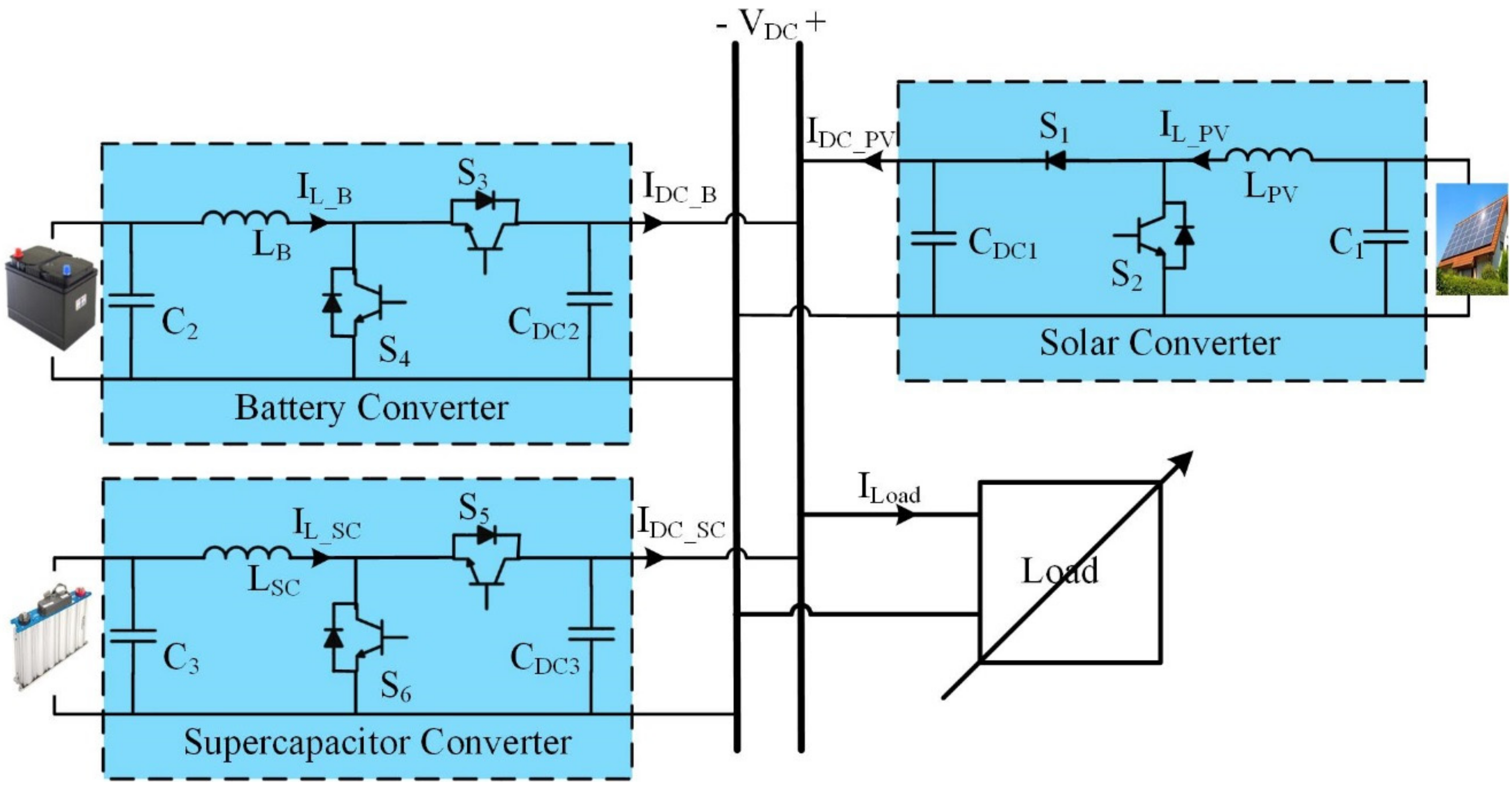
As indicated in Figure 1, the DC nanogrid studied in this research comprises an RES, battery, SC storage units, and a variable load. The RES uses a unidirectional boost converter, while the storage units need a bidirectional boost converter, commonly a class C DC-DC converter. The battery and SC may be managed as a single HESS, in which case they should be co-located or located separately, as recommended in this study, which is suited for distributed energy storage units. With a hierarchical structure based on DBS and droop control, the single-bus DC nanogrid is controlled and decentralized. On the other hand, this report does not mention energy management communication methods. DBS coordinates the functioning of DERs in a decentralized manner by using the DC bus voltage as the communication channel. The current injected by each DER in the nanogrid with droop control is determined by its threshold voltage (VNL), where the injected current is zero, and its droop slope factor Rd, as indicated by (1). The latter affects how the injected current changes when the grid voltage changes.
I D C = V N L V D C 1 R d
where:
R d = Δ V D C Δ I D C
DBS is the nanogrid’s primary control level in the hierarchical structure. The nominal voltage of the DC nanogrid studied in this work is 1 pu. It was designed to work with a ±5% voltage regulation, resulting in an operational DC bus voltage of 0.95 pu to 1.05 pu. The threshold voltage for RESs is often VNL_PV = 1.05 pu, greater than the threshold voltage for the energy storage unit or HESS, 
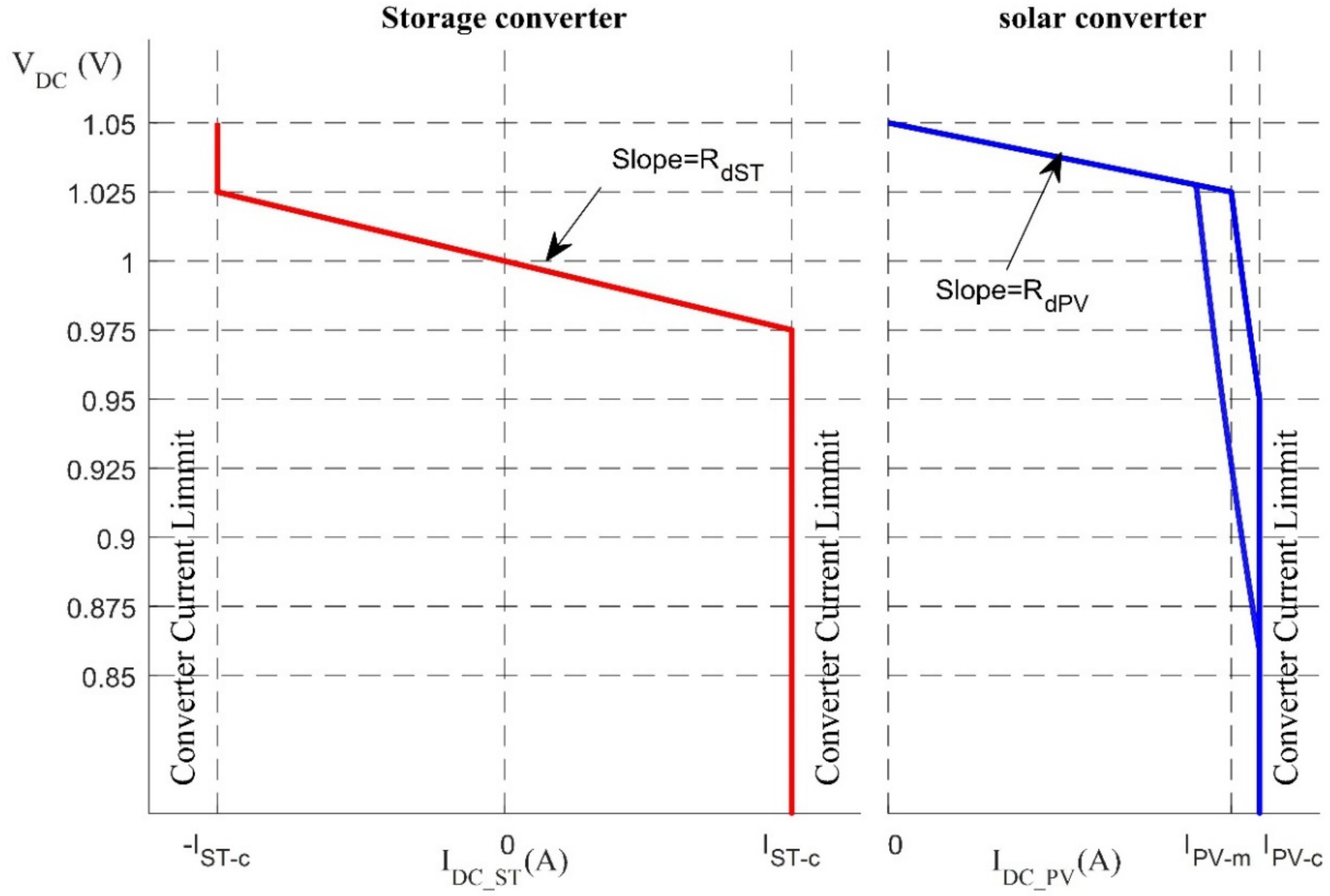
VNL_ST = 1 pu. The DBS model provides RESs the greatest priority to feed the loads if they are available and generate electricity. The solar converter runs in three states, as indicated in Figure 2, by the blue curve: droop, constant power, and constant current limited with unidirectional power flow. The solar converter runs with droop factor RdPV when the DC bus voltage is between 1.05 pu and 1.025 pu. As a result, at VDC = 1.025 pu, the solar produces the maximum power and begins to function at maximum power point tracking (MPPT) with the rated solar irradiance. When the PV’s maximum power is less than the rated power owing to decreasing solar irradiance, the solar converter should begin to function at MPPT before the DC bus voltage goes below 1.025 pu, which may be accomplished by “reprogramming” the solar converter’s V-I curve, as illustrated in Figure 2. The solar converter, for example, should start operating at MPPT with a DC bus voltage of 1.029 pu with a maximum power of 90% of the rated power. The solar converter switches to a constant current-limited mode when the DC bus voltage falls below 0.95 pu for rated solar irradiation [2].

2.2. Power Control and Current Sharing of HESS

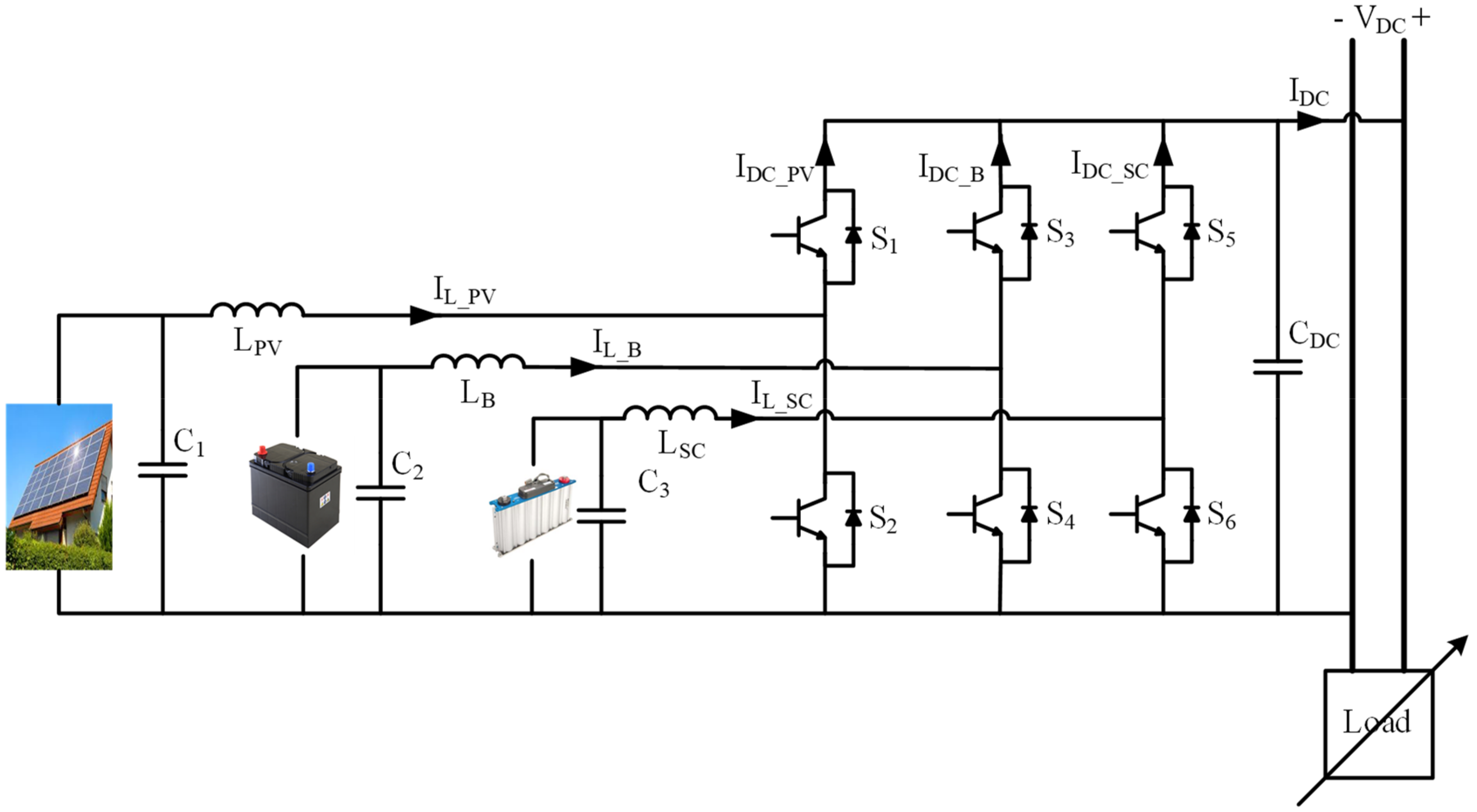
The battery and SC are co-located and operated as a HESS traditionally, as illustrated in 
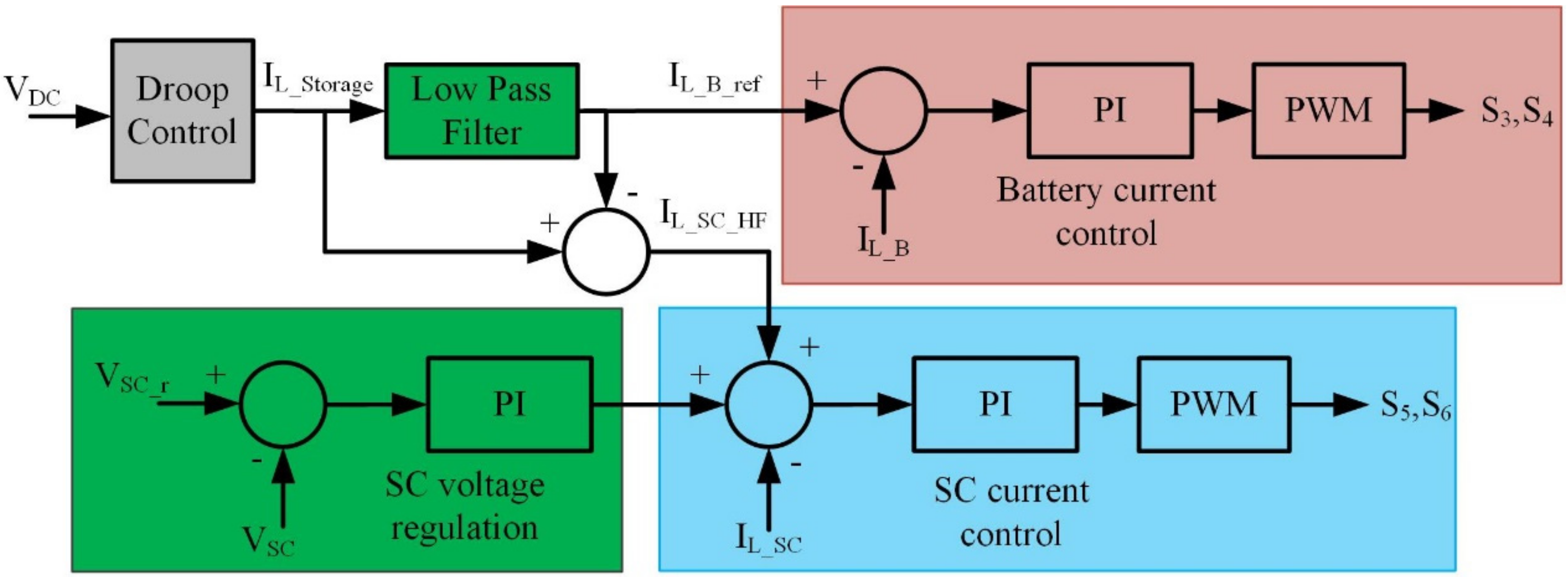
Figure 3, to achieve a specific I vs. V curve or droop characteristic. The supercapacitor operates in conjunction to and parallel with the battery to provide rapid bursts of power that minimize the high-frequency component of the transient battery response, resulting in a smooth transition for the battery. In this technique, the battery inductor current is divided by LPF into low-frequency and high-frequency components, creating the battery inductor reference current and the supercapacitor inductor reference current. The DC bus voltage is detected in a DC nanogrid with droop control, and an outer voltage loop proportional (P) control, which corresponds to the droop action, generates a reference current to be established by the battery and the SC converters. A high-pass filter (HPF) or a low-pass filter (LPF) separates the reference current’s slow and rapid changing components. The inner battery current control loop uses the slow ones as a reference, while the inner SC current control loop uses the fast ones. The outer voltage loop’s bandwidth is approximately 10% of the inner current loops. It is quite good at keeping quickly-changing currents out of the battery. A voltage loop is included in the SC’s control scheme to maintain the SC’s voltage within a desirable range, often 50% to 100% of its rated value. The SC has a state-of-charge with an equal energy capacity to provide and absorb power before exceeding the limit voltage values by setting the reference voltage at 79% of the rated value. Its bandwidth is generally 10% of the HESS’s voltage (droop) loop. Splitting the entire current (IL_Storage) given by HESS into average components, such as the battery reference current, the transient power components, and the SC reference current, improves the battery’s performance but not the DC bus voltage dynamics. Furthermore, HESS’s entire current (IL_Storage) is generated via a common voltage loop, which involves communication between the battery and SC converters. This is not acceptable for usage in nanogrids with decentralized DERs that employ droop control and DC bus signaling.
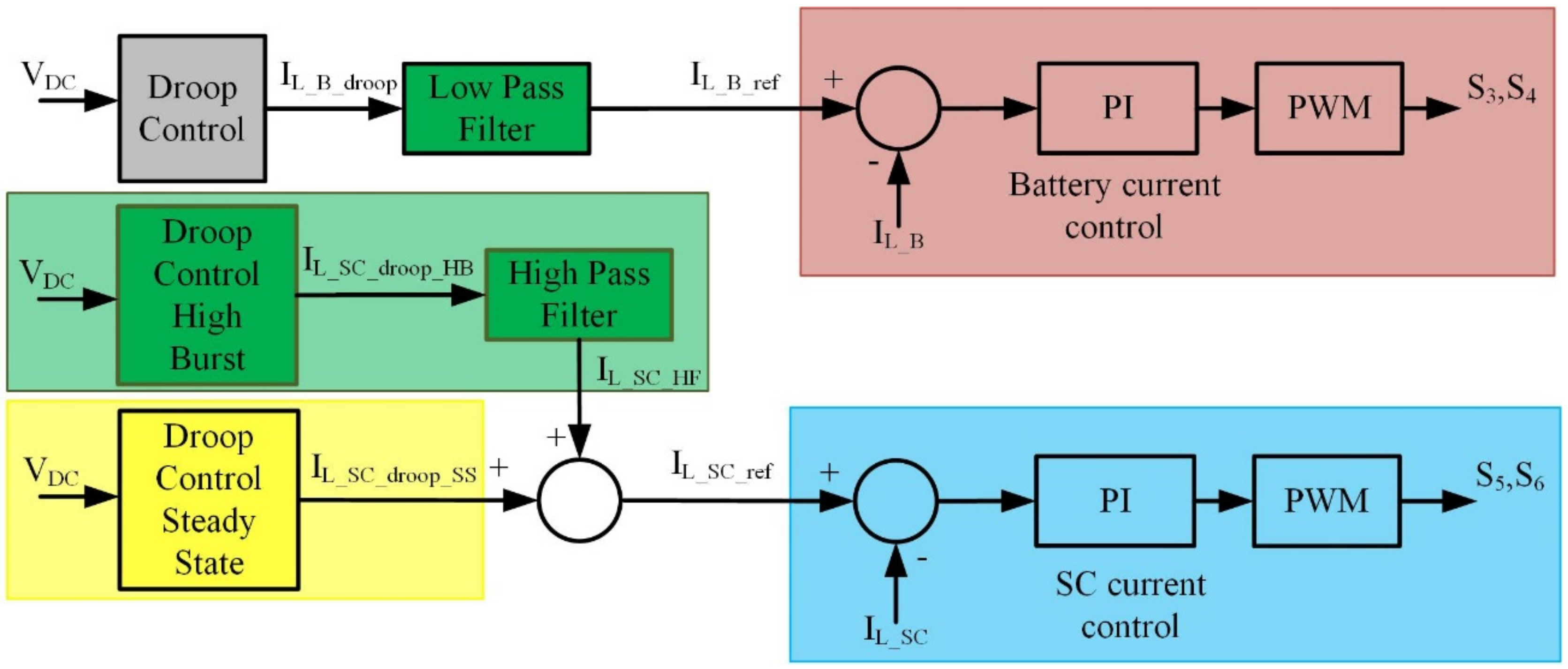
The SC interface is regulated separately from the battery interface in the proposed way depicted in Figure 4, allowing it to offer extra service to the DC nanogrid. This is accomplished using two I vs. V curves for the SC; The first is to provide brief bursts of power to improve the dynamic response of the DC bus voltage and, as a result, to avoid fast-changing currents in the battery. The second is to utilize the energy stored in the supercapacitor as an extra distributed energy resource in the nanogrid, and to help with the dribbling, but not steady-state, voltage control of the DC nanogrid. In the first I vs. V curve, choosing a droop factor for the SC interface substantially lower than the battery’s, results in a larger gain for the SC interface’s outer DC bus voltage loop. Consequently, a given DC bus voltage variance will offer a significantly larger current reference, enhancing dynamic voltage control. Remember that the first I vs. V curve is built to deliver/absorb intense bursts of power. However, the length of the power bursts should be restricted due to its low energy density, which may be completed by adding a HPF with a sufficient time constant in the input of its inner current loop. However, assuming that the SC interface will prevent fast variations in the DC bus voltage and, as a result, sharp variations in the battery interface’s reference current, there is no need for an LPF in the input of the inner current loop of the battery interface. The authors present a detailed design of the first I vs. V curve and the HPF [2]. The method was verified using simulation and experimental results. This paper focuses on designing the second I vs. V curve based on the supervisory control.
The second suggested component for the supercapacitor reference current also helps with power management in the DC nanogrid for an extended period, compared to high-burst power and for a short time compared to the battery. The voltage control of the DC bus should be enhanced/improved by this current component. The long-term current is calculated using a droop control loop using a standard droop constant RdSC2, similar to that used in battery units. Because the DC bus voltage indicates the availability of power in the DC nanogrid, a high voltage level indicates a light load or surplus generation, and it increases the likelihood of a positive power burst, in which case the supercapacitor will be charged to store a large amount of energy. When the DC bus voltage is low, which indicates a high load or a power shortage, there is a greater probability of a negative power burst, in which case the supercapacitor will be discharged, resulting in low energy stored. The dribbling current is calculated using a droop control loop using a standard droop constant RdSC2, similar to that used in battery units. Because the DC bus voltage indicates the availability of power in the DC nanogrid, a high voltage level indicates a light load or surplus generation, which increases the likelihood of a positive power burst, in which case the supercapacitor will be charged to store a large amount of energy. When the DC bus voltage is low, which indicates a high load or a power shortage, there is a greater probability of a negative power burst, in which case the supercapacitor will be discharged, resulting in low energy stored. The change of the operating voltage of the supercapacitor between 50% and 100% of its rated voltage based on the information from the DC bus voltage gives 75% of its stored energy to deal with the maximum sudden change for both positive and negative changes. When the DC bus voltage is about 1.025 pu, the supercapacitor voltage is set to 100% of its maximum voltage, indicating that the DC bus has more available power and is projected to have the most significant positive load change. When the DC bus voltage is 0.975 pu, the supercapacitor voltage is set to 50% of its maximum voltage since the DC bus has less available power and is projected to have the most negative load change. As the DC bus voltage fluctuates from 1.025 pu to 0.975 pu, the supercapacitor voltage varies from 100% to 50% of its maximum voltage. However, the suggested method would add a second control loop, which would make the control system slightly more complicated than the primary one while not adding to the electrical system’s complexity.
The supercapacitor charging and discharging control is a droop control based on the DC bus, which has a lower influence on the DC bus voltage regulation. Varying the threshold voltage of the supercapacitor (VNL_SC) as a function of the supercapacitor voltage controls the supercapacitor voltage. This reduces the risk of overcharging the supercapacitor, giving it a better chance of feeding power to the DC nanogrid. Furthermore, with a low supercapacitor voltage, the supercapacitor does not discharge and has a better chance of being charged again. The supercapacitor’s threshold voltage fluctuates as a function of the supercapacitor voltage. The suggested logic changes the threshold voltage charges or discharges the supercapacitor to a voltage level (VSC) where the supercapacitor’s steady-state current is zero. In other words, the DC bus voltage in the steady state equals the supercapacitor’s threshold voltage at that voltage (VSC). The threshold voltage level is based on the DC bus voltage to cope with the most significant sudden change in the load current and the power availability in the nanogrid. This implies that the supercapacitor threshold voltage is adjusted to maintain the capacity to handle intense bursts of power.
The most significant high burst of power (PHSC max) that a supercapacitor can provide for a given voltage level (VSC) and duration (Δt) is equal to:
P H S C _ m a x = Δ E Δ t
where ΔE is:
Δ E = 1 2 C V S C 1 2 V S C 2 2
Substituting ΔE from (4) into (3) gives:
P H E C _ m a x = 1 2 C Δ t V S C 2 V S C _ m i n 2
For a lossless converter, the supercapacitor’s maximum high burst power is equal to the converter’s output power.
P H E C _ m a x = I D C _ S C _ h V D C _ m i n
After that, for (RdSC1) of the high burst of power, using the droop Equation in (1) to substitute IDC_SC_h:
P H E C _ m a x = V N L _ S C V D C _ m i n R d S C 1 V D C _ m i n
Solve for (VNL_SC) by equating Equations (5) and (7).
V N L _ S C = 1 2 C Δ t V S C 2 V S C _ m i n 2 V D C _ m i n R d S C 1 + V D C _ m i n
For a maximum high burst of power PHEC_max, the discharging time (Δt) is:
Δ t m a x = 1 2 C V S C _ m a x 2 V S C _ m i n 2 P H E C _ m a x
Considering the burst of power when the DC bus voltage changed from VDC_max to VDC_min:
P H E C _ m a x = V D C _ m a x V D C _ m i n R d S C 1 V D C _ m i n
Then, by substituting (10) in (9) and substituting (Δt) in (8), one finds VNL_SC as:
V N L _ S C = V D C _ m a x V D C _ m i n V S C _ m a x 2 V S C _ m i n 2 V S C 2 V S C _ m i n 2 + V D C _ m i n
That leads to:
V N L _ S C = K N V S C 2 V S C _ m i n 2 + V D C _ m i n
where KN is constantly given by:
K N = V D C _ m a x V D C _ m i n V S C _ m a x 2 V S C _ m i n 2
where (VDC_max) and (VDC_min) are the maximum and minimum DC bus voltages for the storage unit to operate in droop mode, respectively, and are equivalent to 1.025 pu and 0.975 pu from the I vs. V curve in Figure 2. The battery and SC operate with the converter current limiting when the DC bus voltage is more than 1.025 pu and less than 0.975 pu, resulting in no change in the injected current. While (VSC_max) is the supercapacitor’s rated voltage, (VSC_min) is the supercapacitor’s minimum voltage, which is equal to 50% of (VSC_max). 
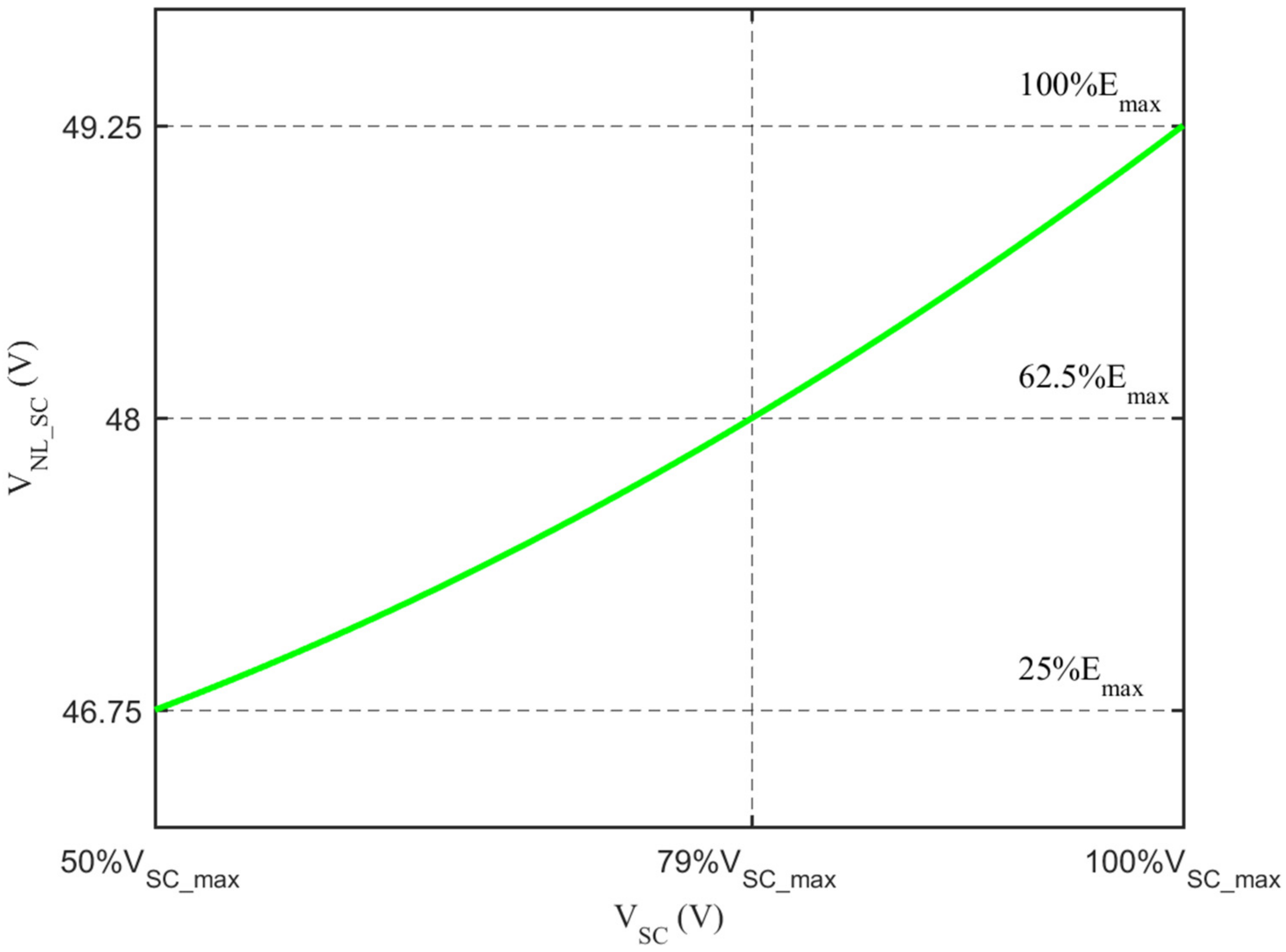
Figure 5 displays the (VNL_SC) at various supercapacitor voltage levels.
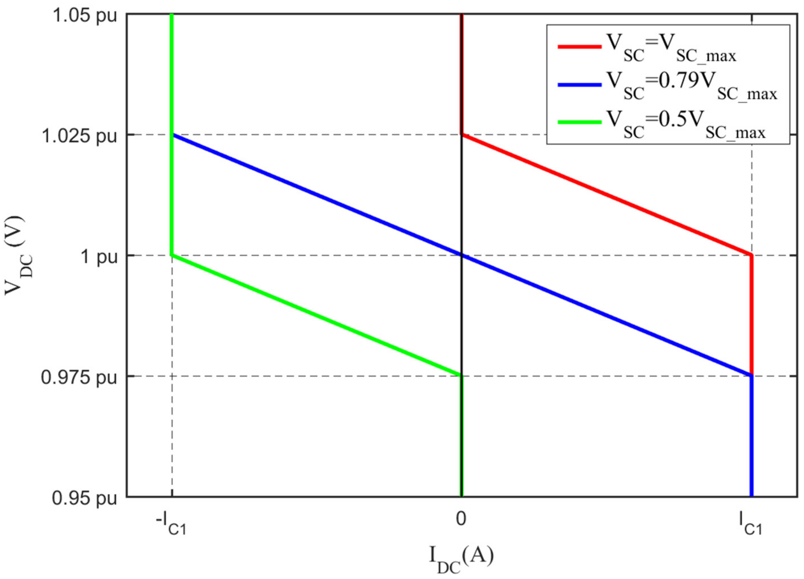
Figure 6 shows the dribbling supercapacitor I vs. V curve at supercapacitor voltages of 100%, 79%, and 50% of VSC_max. The supercapacitor has a VNL_SC = VNL_B = 1 pu at VSC~79 % of VSC_max (blue curve), and the supercapacitor contributes the same amount of power as the battery. When the supercapacitor has a voltage of 50% of VSC_max, the threshold voltage is VNL_SC = 0.975 pu (green curve). Figure 2 shows that at 0.975 pu, the battery operates at the maximum discharging current and does not have a positive pulse current. Furthermore, when the threshold voltage is VNL_SC = 1.025 pu, the supercapacitor stores the most energy (red curve). Figure 2 shows that at 1.025 pu, the battery operates at the maximum charging current and does not have a negative pulse current.

3. Results and Discussion

A 48 V DC nanogrid with a PV-based RES, a battery unit, a SC unit, and a variable load is addressed as a case study in this research. At rated solar irradiance, the PV panel generates a maximum power of 213 W, 7.35 A, and 29 V. Due to converter losses, the PV unit’s maximum (rated) injected power is 200 W. To meet the voltage levels shown in Section 2, the DC bus voltage in the MPPT area should be between 49.2 V and 45.6 V, with the solar converter injecting 4.1 A and 4.4 A, respectively.
The proposed scheme with supervisory control for the HESS is compared to the scheme without supervisory control, which may also be utilized in non-co-located battery and SC units, in the performance investigation in the following sections. Because the HESS droop factor (Rd_ST) is 0.289 Ω, the battery converter droop factor and the SC dribble component droop factor are RdB = RdSC2 = Rd_ST = 0.289 Ω. The HESS threshold voltage (VNL_ST) is 48 V, and the current limit value (IST-c = IPV-c = 4.4 A) is the maximum current delivered by the PV converter. The threshold voltages of the battery and SC converters, VNL_B and VNL_SC, are identical to VNL_ST in the control scheme without supervisory control, and their rated currents are equal to the maximum current provided by the PV converter (IB-c = ISC-c = IPV-c = 4.4 A). The VNL_SC varies with supervisory control, as indicated in section two. However, the SC’s high burst of power component, RdSC1 = 0.0145 Ω, should be 20 times lower than the battery’s, as explained in [2]. For Ts = 0.22 s, the HPF cut-off frequency for the SC control loop was computed as reported in [2] and is equal to 43.5 Hz.
Except for the RES’s unidirectional characteristic, all components of DC-DC converters are quite identical in terms of power electronic interfaces. In the simulation studies and the experimental setup, the power converters are implemented using a single three-phase DC-AC converter, as illustrated in Figure 7. The DC bus (nanogrid) voltage capacitor is equivalent to 1500 µF. To build the conventional class C DC-DC converters, LC filters (100 µH and 470 µF) are connected between the mid-points of the three-phase inverter legs and the storage and source components. The converters use PWM and have a 20 kHz switching frequency.
All DERs may utilize the same current control loop. A PI type-III controller was devised for the same equivalent plant with the transfer function (14) [2,19]. They were developed with a phase margin of PM = 80° and a crossover frequency of fx = 2 kHz (10 percent of the switching frequency). For VPV = VBat = VSC = 29 V, the following plant characteristics were assumed: VDC = 48 V, IDC = 4.44 A, R = 10.8 Ω, L = 100 µH, C = 1500 µF, and D = 0.46. R was chosen as the greatest load that the RES could handle on its own. Finally, KPI = 0.0114, τ = 171 µs, and TP = 37 µs are calculated as PI controller parameters.
G d i s = i ˜ L s d ˜ s = C V D C s + 2 I D C L C s 2 + L R s + 1 D 2

3.1. Simulation Results

For simulation investigations, MATLAB/Simulink is employed. The goal is to look at the potential benefits of the second droop component in the SC unit control on the DC nanogrid voltage dynamic regulation. This should, in theory, not affect the SC unit’s capacity to attenuate the battery’s high frequency and fast-changing currents. To test this capability, the solar converter operates in MPPT mode while the DC nanogrid’s power consumption fluctuates between no-load and full load. There is no power demand from the DC nanogrid from t = 0 s to 0.05 s, and the storage unit(s) absorbs the entire 200 W provided by the RES. The DC nanogrid is then linked to a full-load impedance of 5.2 Ω, supplied at full power by both the RES and storage unit(s). This operational state persists until the load is eliminated after 0.3 s. This is the most significant normal disturbance that the DC nanogrid will experience, and it will be used to compare the proposed control scheme to the single droop component control of the SC unit in the HESS. The system’s parameters are listed in the previous sections.
The critical system waveforms for the single droop scheme are shown in Figure 8. The DC nanogrid voltage (top screen) is around 49.25 V when no load is applied. With a boost inductor current (average) of roughly 7.35 A, the solar converter operates in MPPT mode, bottom screen. The battery’s average absorbed current (negative sign) is 8.4 A, whereas the SC is zero, as expected. Following the load step, the SC injects a higher current while the battery current gradually increases until it delivers all of the HESS currents as intended. Just before 0.3 s, the DC bus voltage reaches its steady-state value of 46.75 V. When the load is removed at t = 0.3 s, the HESS needs to absorb rated power again; a similar response in terms of current magnitudes and settling times can be observed.
In the dual droop scheme, based on (12), the supercapacitor threshold voltage is VNL_SC = 49.25 V when the supercapacitor voltage is around VSC_max = 36 V. The battery is charged with the maximum current (current limiting) at a DC bus voltage of 49.25 V based on the I vs. V curve shown in Figure 2. That is, the battery does not anticipate a negative current increase, and the supercapacitor does not anticipate absorbing a high-frequency component of the current. On the other hand, when the DC bus voltage drops due to a load increase or a power shortage, the battery may suffer from a positive current, and the SC supplies a high-frequency component of the current. In this situation, the DC bus voltage in the droop control zone is managed by two resources: the SC and battery, which improves the DC bus voltage regulation. Based on (2), this will reduce the step change in the storage current. Furthermore, because the difference in voltage (VNL_SC-VDC) is greater than (VNL_B-VDC), the SC will contribute more current and hence less variation in the battery current. Figure 9 shows this at t = 0.05 s, without affecting the SC’s capacity to deal with the high burst of power. The HESS must absorb rated power when the load is withdrawn at t = 0.3 s; a similar reaction in terms of current magnitudes and settling time is observed.
When the supercapacitor voltage is about VSC_min = 18 V, the supercapacitor threshold voltage is VNL_SC = 46.75 V. The battery is discharged with the maximum current (current limiting) at a DC bus voltage of 46.75 V based on I vs. V curve shown in Figure 2. That is, the battery does not anticipate a positive current increase, and the supercapacitor does not anticipate supplying a high-frequency component of the current. On the other hand, when the DC bus voltage increases due to a load decrease or a power excess, the battery may suffer from a negative current, and the SC absorbs a high-frequency component of the current. In this situation, the DC bus voltage in the droop control zone was managed by two resources: the SC and battery, which improves the DC bus voltage regulation. Based on (2), this reduces the step change in the storage current. Furthermore, because the difference voltage (VNL_SC-VDC) is greater than (VNL_B-VDC), the SC absorbs more current; hence, there is less variation in the battery current. Figure 10 shows this at t = 0.05 s, without affecting the SC’s capacity to deal with the high burst of power. The HESS must supply rated power when the load is withdrawn at t = 0.3 s; a similar reaction in terms of current magnitudes and settling time is observed.
The same performance could be achieved when the supercapacitor threshold voltage is VNL_SC = 48 V at VSC ≈ 28 V, as illustrated in Figure 11. However, the SC and the batter have the same contribution to the regulation of the DC bus.

3.2. Experimental Results

A DC nanogrid with an RES, two energy storage units, and a variable load were built in the laboratory. An Agilent Solar Array Simulator (SAS) (E4350B) was employed to simulate a solar array. At rated solar irradiation, it was set to provide a maximum power of 213 W, 7.35 A, and 29 V. The energy storage devices used 165 F Maxwell supercapacitor modules (BMOD0165 P048) with a rated voltage of 48 V. The first serves as a battery, while the second serves as a SC. In this experiment, a Semikron “MiniSKiiP 8 Three-phase 1200 V Powerboard” with a MiniSKiiP 83 AC power module and a SKHI61 IGBT driver was employed as the power electronics interface. The values of passive components, control parameters, and other variables employed in the experiment are listed in Section 3. A dSPACE DS-1103 rapid prototyping system with a 20 μs time step is used to implement the control methods. Simulink C coder used a Real-time interface (RTI) to convert the control diagram from MATLAB/Simulink to dSPACE code, which generated the dSPACE code. This is not the fastest or shortest code, but it is sufficient in proof-of-concept tests. The full DC nanogrid load impedance was achieved with eight parallel switchable 44 Ω resistors. Figure 12 shows the experimental setup. Due to the proposed system’s use of the same supercapacitor and power electronics interface for power and energy management, the cost of implementing a nanogrid will not rise. However, better voltage control improves dynamic response and battery life, lowering the system’s long-term cost.
Having demonstrated the improved performance of the proposed scheme over the conventional HESS control scheme using simulations. The experimental results are provided to demonstrate the feasibility of the proposed control scheme. The supercapacitor threshold voltage is VNL_SC = 49.25 V when the supercapacitor voltage is around VSC = 36 V. When the DC bus voltage is less than 49.25 V, the supercapacitor charges the battery, and when the DC bus voltage is less than 48 V, the supercapacitor shares the load power with the battery. When the supercapacitor voltage exceeds VSCO = 28.44 V, the supercapacitor supplies more power to the load than the battery. The supercapacitor injects no current when the DC bus voltage is 49.25 V and the supercapacitor voltage is 36 V; as shown in Figure 13, the supercapacitor injects no current. Furthermore, when the load is changed from no-load to 5.2 Ω at t = 0.2 s, the supercapacitor injects the rapid changing component of the load current, resulting in a seamless transition of the DC bus voltage and battery inductor current. Furthermore, when the load is returned to no-load at t = 0.5 s, the fast-changing component of the load current is absorbed, as seen in Figure 13. However, the supercapacitor contributes more to power-sharing than the battery in feeding the load due to its high energy level. Furthermore, the dribbling component of the supercapacitor minimizes the voltage drop in the DC bus with load fluctuation, dropping the DC bus voltage to 48 V for 5.2 Ω compared to 46.75 V for 5.2 Ω without the dribbling component, as shown in Figure 8. In the droop zone, the lesser voltage variance minimizes the variation in the battery current, resulting in a smoother transition.
The supercapacitor threshold voltage is VNL_SC = 46.75 V when the supercapacitor voltage is about VSC = 18 V. As a result, the supercapacitor charges even when the DC bus voltage is less than 48 V. Because the supercapacitor has a low level of energy stored, it will not inject power to contribute to the DC nanogrid. When the DC bus voltage is 46.75 V and the supercapacitor voltage is 18 V, as shown in Figure 14, the supercapacitor injected current is zero. Furthermore, the supercapacitor absorbs the fast-changing component of the current, resulting in a smooth transition of the battery inductor current from 5.2 Ω to no-load at t = 0.2 s, as shown in Figure 14. Furthermore, when the load returns to 5.2 Ω at t = 0.5 s, the fast-changing component of the current is injected. Furthermore, the supercapacitor’s dribble component minimizes the voltage change in the DC bus as the load varies, resulting in less variation in the battery current in the droop zone and a smoother transition.

4. Conclusions

Hybrid energy storage systems (HESSs) that include batteries and supercapacitors (SCs) can play a significant part in the operation of autonomous DC nanogrids that make use of stochastic renewable energy sources (RES) and highly variable loads. In droop-controlled DC grids, the batteries and SCs are typically co-located, and the control of the grid is accomplished with a single I vs. V curve. Filters that either have a low pass or high pass characteristic can be utilized to extract the correct current contributions from the battery (slow components) and SC (rapid components) (HPFs). Moreover, the authors of this work recommended an additional I vs. V curve for SCs, which would allow SCs to contribute to slow components. The regulation of the DC bus voltage is improved when the SCs are contributed by the slow components. As a result, an improvement was made to the current response of the battery during the droop zone.

Author Contributions

Conceptualization, A.M.A.M. and A.A.-Q.; Formal analysis, A.M.A.M. and L.A.C.L.; Funding acquisition, A.M.A.M. and L.A.C.L.; Investigation, A.M.A.M.; Methodology, A.M.A.M., A.A.-Q. and L.A.C.L.; Validation, A.M.A.M. and A.A.-Q.; Writing—original draft, A.M.A.M., A.A.-Q. and L.A.C.L.; Writing—review & editing, A.M.A.M., A.A.-Q. and L.A.C.L. All authors have read and agreed to the published version of the manuscript.

Funding

This research was funded by the The University of Jordan and Natural Sciences and Engineering Research Council (NSERC) of Canada.

Acknowledgments

The authors appreciate the financial support provided by The University of Jordan, through the Deanship of Scientific Research, and of the Natural Sciences and Engineering Research Council (NSERC) of Canada.

Conflicts of Interest

The authors declare no conflict of interest.

References

  1. Irtija, N.; Sangoleye, F.; Tsiropoulou, E.E. Contract-Theoretic Demand Response Management in Smart Grid Systems. IEEE Access 2020, 8, 184976–184987. [Google Scholar] [CrossRef]
  2. Malkawi, A.; Lopes, L.A. Improved Dynamic Voltage Regulation in a Droop Controlled DC Nanogrid Employing Independently Controlled Battery and Supercapacitor Units. Appl. Sci. 2018, 8, 1525. [Google Scholar] [CrossRef] [Green Version]
  3. Alepuz, S.; Busquets-Monge, S.; Bordonau, J.; Gago, J.; González, D.; Balcells, J. Interfacing Renewable Energy Sources to the Utility Grid Using a Three-Level Inverter. IEEE Trans. Ind. Electron. 2006, 53, 1504–1511. [Google Scholar] [CrossRef]
  4. Sartori, I.; Napolitano, A.; Voss, K. Net Zero Energy Buildings: A Consistent Definition Framework. Energy Build. 2012, 48, 220–232. [Google Scholar] [CrossRef] [Green Version]
  5. Wei, Z.; Meng, S.; Xiong, B.; Ji, D.; Tseng, K.J. Enhanced Online Model Identification and State of Charge Estimation for Lithium-Ion Battery with a FBCRLS Based Observer. Appl. Energy 2016, 181, 332–341. [Google Scholar] [CrossRef]
  6. Wei, Z.; Zhao, J.; Ji, D.; Tseng, K.J. A Multi-Timescale Estimator for Battery State of Charge and Capacity Dual Estimation Based on an Online Identified Model. Appl. Energy 2017, 204, 1264–1274. [Google Scholar] [CrossRef]
  7. Manandhar, U.; Tummuru, N.R.; Kollimalla, S.K.; Ukil, A.; Beng, G.H.; Chaudhari, K. Validation of Faster Joint Control Strategy for Battery-and Supercapacitor-Based Energy Storage System. IEEE Trans. Ind. Electron. 2017, 65, 3286–3295. [Google Scholar] [CrossRef]
  8. Arunkumar, C.R.; Manthati, U.B.; Punna, S. Supercapacitor Voltage Based Power Sharing and Energy Management Strategy for Hybrid Energy Storage System. J. Energy Storage 2022, 50, 104232. [Google Scholar] [CrossRef]
  9. Korada, D.M.R.; Mishra, M.K. Adaptive Power Management Algorithm for Multi-Source DC Microgrid System. Int. J. Emerg. Electr. Power Syst. 2022. [Google Scholar] [CrossRef]
  10. Caparrós Mancera, J.J.; Saenz, J.L.; López, E.; Andújar, J.M.; Segura Manzano, F.; Vivas, F.J.; Isorna, F. Experimental Analysis of the Effects of Supercapacitor Banks in a Renewable DC Microgrid. Appl. Energy 2022, 308, 118355. [Google Scholar] [CrossRef]
  11. Ravada, B.R.; Tummuru, N.R. Control of a Supercapacitor-Battery-PV Based Stand-Alone DC-Microgrid. IEEE Trans. Energy Convers. 2020, 35, 1268–1277. [Google Scholar] [CrossRef]
  12. Abbey, C.; Li, W.; Joos, G. An Online Control Algorithm for Application of a Hybrid ESS to a Wind–Diesel System. IEEE Trans. Ind. Electron. 2010, 57, 3896–3904. [Google Scholar] [CrossRef]
  13. Mendis, N.; Muttaqi, K.M.; Perera, S. Management of Battery-Supercapacitor Hybrid Energy Storage and Synchronous Condenser for Isolated Operation of PMSG Based Variable-Speed Wind Turbine Generating Systems. IEEE Trans. Smart Grid 2014, 5, 944–953. [Google Scholar] [CrossRef]
  14. Hredzak, B.; Agelidis, V.G.; Jang, M. A Model Predictive Control System for a Hybrid Battery-Ultracapacitor Power Source. IEEE Trans. Power Electron. 2013, 29, 1469–1479. [Google Scholar] [CrossRef]
  15. Shen, J.; Khaligh, A. A Supervisory Energy Management Control Strategy in a Battery/Ultracapacitor Hybrid Energy Storage System. IEEE Trans. Transp. Electrif. 2015, 1, 223–231. [Google Scholar] [CrossRef]
  16. Tummuru, N.R.; Mishra, M.K.; Srinivas, S. Dynamic Energy Management of Renewable Grid Integrated Hybrid Energy Storage System. IEEE Trans. Ind. Electron. 2015, 62, 7728–7737. [Google Scholar] [CrossRef]
  17. Kakigano, H.; Nishino, A.; Ise, T. Distribution Voltage Control for DC Microgrid with Fuzzy Control and Gain-Scheduling Control. In Proceedings of the 8th International Conference on Power Electronics-ECCE Asia, Jeju, Korea, 30 May 2011–3 June 2011; IEEE: Piscataway, NJ, USA, 2011; pp. 256–263. [Google Scholar]
  18. Chedid, R.; Rahman, S. Unit Sizing and Control of Hybrid Wind-Solar Power Systems. IEEE Trans. Energy Convers. 1997, 12, 79–85. [Google Scholar] [CrossRef] [Green Version]
  19. Kollimalla, S.K.; Mishra, M.K.; Narasamma, N.L. Design and Analysis of Novel Control Strategy for Battery and Supercapacitor Storage System. IEEE Trans. Sustain. Energy 2014, 5, 1137–1144. [Google Scholar] [CrossRef]
Figure 1. DC nanogrid.
Inventions 07 00055 g001
Figure 2. I vs. V curves for a DC nanogrid consisting of storage and RESs.
Inventions 07 00055 g002
Figure 3. Block diagram for the conventional control scheme of HESS.
Inventions 07 00055 g003
Figure 4. Block diagram for the proposed control scheme of HESS. (Remove LPF from Batt).
Inventions 07 00055 g004
Figure 5. Supercapacitor threshold voltage as a function of supercapacitor voltage based on (11).
Inventions 07 00055 g005
Figure 6. The dribbling supercapacitor I vs. V curve.
Inventions 07 00055 g006
Figure 7. DC nanogrid power electronics interfaces.
Inventions 07 00055 g007
Figure 8. Simulation results for the single droop control scheme when the load is changed from no-load to 5.2 Ω (full nanogrid load) and back to no-load.
Inventions 07 00055 g008
Figure 9. Simulation for dual droop scheme at supercapacitor voltage VSC = 36 V when the load changed from no-load to 5.2 Ω and back to no-load.
Inventions 07 00055 g009
Figure 10. Simulation for dual droop scheme at supercapacitor voltage VSC = 18 V when the load changed from 5.2 Ω to no-load and back to 5.2 Ω.
Inventions 07 00055 g010
Figure 11. Simulation for dual droop scheme at supercapacitor voltage VSC = 28.44 V when the load changed from 10.8 Ω to 5.2 Ω and back to 10.8 Ω.
Inventions 07 00055 g011
Figure 12. Picture of the experimental setup assembled in the laboratory.
Inventions 07 00055 g012
Figure 13. Experimental result for proposed dual scheme control at supercapacitor voltage VSC = 36 V when the load changed from no-load to 5.2 Ω and back to no-load.
Inventions 07 00055 g013
Figure 14. Experimental result for the proposed dual scheme control at supercapacitor voltage VSC = 18 V when the load changed from 5.2 Ω to no-load and back to 5.2 Ω.
Inventions 07 00055 g014
Publisher’s Note: MDPI stays neutral with regard to jurisdictional claims in published maps and institutional affiliations.

