Numerical Study of Latent Heat Thermal Energy Storage Enhancement by Nano-PCM in Aluminum Foam


Abstract
1. Introduction
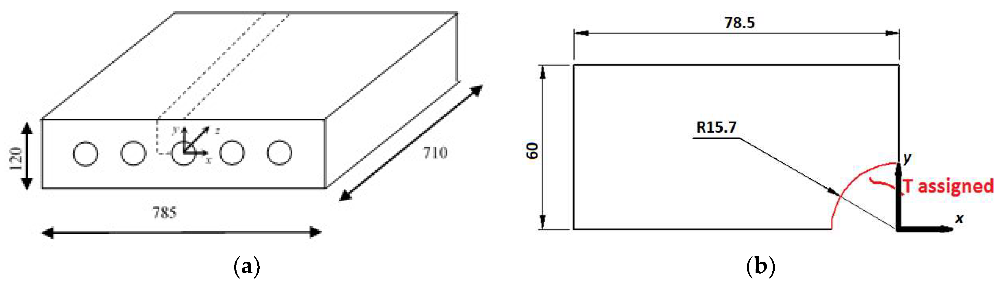
2. Physical Model
3. Numerical Model
- -
- Pipe Surface: assigned temperature Tw at 343.15 K.
- -
- The other surfaces are adiabatic.
- -
- The system is assumed to be at 300 K.
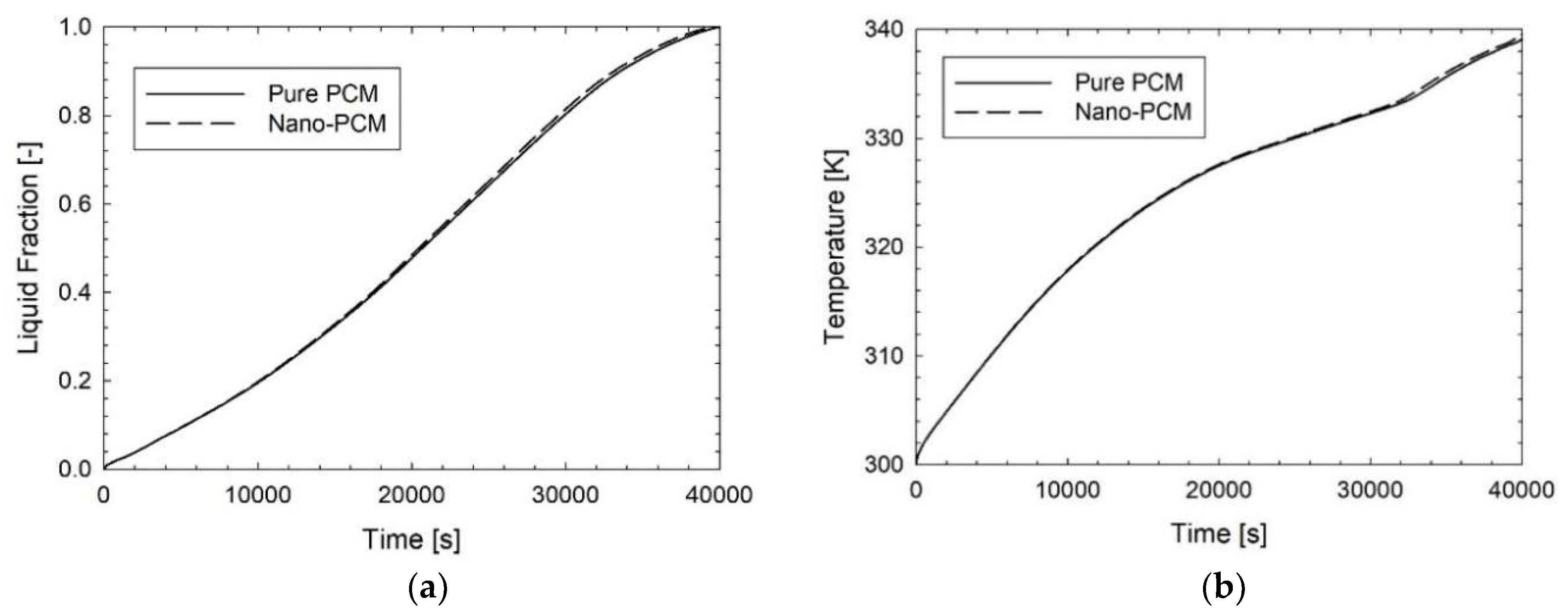
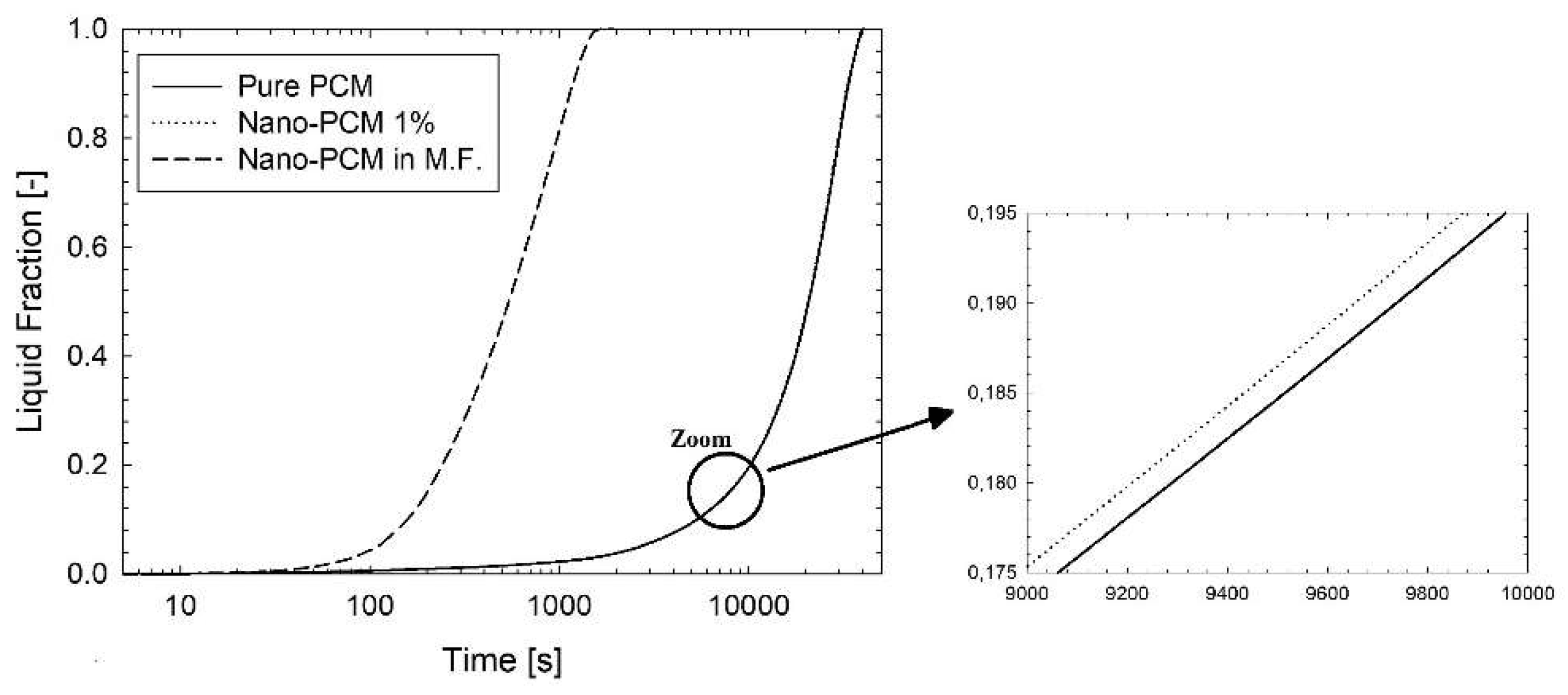
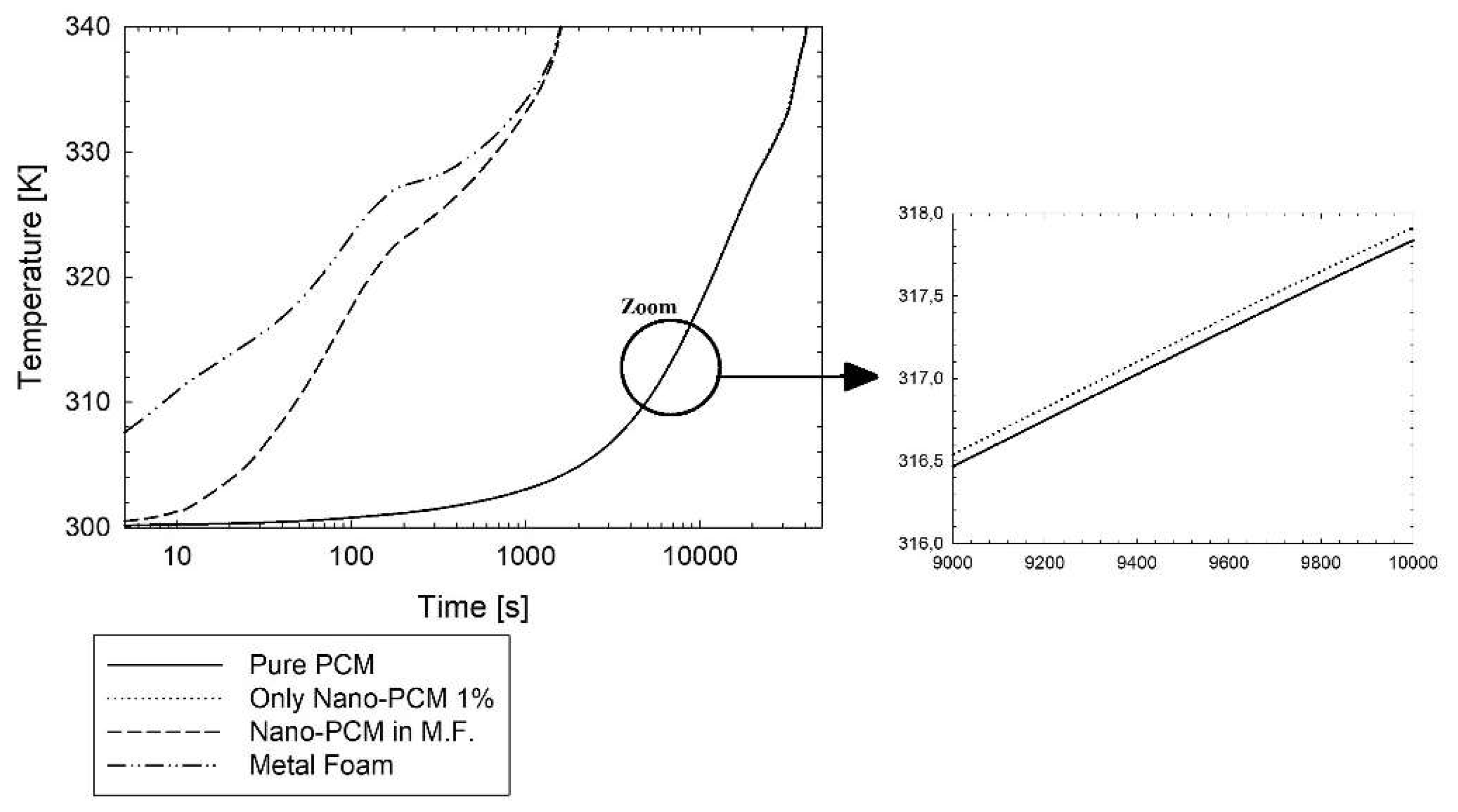
4. Results and Discussions
5. Conclusions
Author Contributions
Funding
Conflicts of Interest
Abbreviations
| Amush | Mushy constant kg·m−3·s−1 |
| CF | drag factor coefficient |
| c | specific heat, J·kg−1·K−1 |
| df | fiber diameter, m |
| dp | cell diameter, m |
| hsf | interfacial heat transfer coefficient, W·m−2·K−1 |
| HL | latent heat, J·kg−1 |
| k | thermal conductivity, W·m−1·K−1 |
| K | porous permeability, m2 |
| L | Characteristic length, m |
| p | relative pressure, Pa |
| Pr | Prandtl number |
| r | radius tube, m |
| Re | Reynolds number |
| S | source term N·m−3 |
| t | time s |
| T | temperature, K |
| Vol | volume |
| V | velocity, m·s−1 |
| x | cartesian axis direction, m |
| y | cartesian axis direction, m |
| z | cartesian axis direction, m |
| Greek symbols | |
| αsf | specific surface area density, m−1 |
| β | liquid fraction |
| ε | porosity |
| γ | thermal expansion coefficient K−1 |
| μ | dynamic viscosity, kg·m−1·s−1 |
| ρ | density, kg·m−3 |
| ψ | volume concentration of nanoparticles |
| ω | number of pores per inch, m−1 |
| Subscripts | |
| 0 | operating condition |
| Al2O3 | Aluminium oxide |
| df | fiber diameter |
| Foam | metal foam |
| i | initial |
| Liquidus | liquidus temperature |
| NANOPCM | Nano-enhanced PCM |
| PCM | phase change material |
| Solidus | solidus temperature |
| TOTAL | whole domain |
| w | wall |
| Wax | paraffin wax RT58 |
References
- Alva, S.; Lin, Y.; Fang, G. An overview of thermal energy storage systems. Energy 2018, 144, 341–378. [Google Scholar] [CrossRef]
- Gil, A.; Medrano, M.; Martorell, I.; Lazaro, A.; Dolado, P.; Zalba, B.; Cabeza, L. State of the art on high temperature thermal energy storage for power generation. Part 1—Concepts, materials and modellization. Renew. Sustain. Energy Rev. 2010, 14, 31–55. [Google Scholar] [CrossRef]
- Khan, Z.; Khan, Z.; Ghafoor, A. A review of performance enhancement of PCM based latent heat storage system within the context of materials, thermal stability and compatibility. Energy Convers. Manag. 2016, 115, 132–158. [Google Scholar] [CrossRef]
- Khyad, A.; Samrani, H.; Bargach, M.N. State of the art review of thermal energy storage systems using PCM operating with small temperature differences: Focus on Paraffin. J. Mater. Environ. Sci. 2016, 7, 1184–1192. [Google Scholar]
- Colla, L.; Ercole, D.; Fedele, L.; Mancin, S.; Manca, O.; Bobbo, S. Nano-phase change materials for electronics cooling applications. ASME J. Heat Transf. 2017, 139, 052406. [Google Scholar] [CrossRef]
- Zhao, C.Y.; Lu, W.; Tian, Y. Heat transfer enhancement for thermal energy storage using metal foams embedded within phase change materials (PCMs). Sol. Energy 2010, 84, 1402–1412. [Google Scholar] [CrossRef]
- Shin, D.; Banerjee, D. Enhanced Specific Heat of Silica Nanofluid. ASME J. Heat Transf. 2010, 133, 024501. [Google Scholar] [CrossRef]
- Chieruzzi, M.; Cerritelli, G.F.; Miliozzi, A.; Kenny, J.M. Effect of nanoparticles on heat capacity of nanofluids based on molten salts as PCM for thermal energy storage. Nanoscale Res. Lett. 2013, 8, 448. [Google Scholar] [CrossRef] [PubMed]
- Ercole, D.; Manca, O.; Vafai, K. An investigation of thermal characteristics of eutectic molten salt-based nano fluids. Int. Comm. Heat Mass Transf. 2017, 87, 98–104. [Google Scholar] [CrossRef]
- Bayat, M.; Faridzadeh, M.R.; Toghraie, D. Investigation of finned heat sink performance with nano enhanced phase change material (NePCM). Therm. Sci. Eng. Prog. 2018, 5, 50–59. [Google Scholar] [CrossRef]
- Ibrahim, N.I.; Al-Sulaiman, A.F.; Rahmana, S.; Yilbas, B.S.; Sahinb, A.Z. Heat transfer enhancement of phase change materials for thermal energy storage applications: A critical review. Renew. Sustain. Energy Rev. 2017, 74, 26–50. [Google Scholar] [CrossRef]
- Siahpush, A.; O’Brien, J.; Crepeau, J. Phase change heat transfer enhancement using copper porous foam. ASME J. Heat Transf. 2008, 130, 082301. [Google Scholar] [CrossRef]
- Tian, Y.; Zhao, C.Y. A numerical investigation of heat transfer in phase change materials (PCMs) embedded in porous metals. Energy 2011, 36, 5539–5546. [Google Scholar] [CrossRef]
- Fang, Y.; Niu, J.; Deng, S. Numerical analysis for maximizing effective energy storage capacity of thermal energy storage systems by enhancing heat transfer in PCM. Energy Build. 2018, 160, 10–18. [Google Scholar] [CrossRef]
- Hossain, R.; Mahmud, S.; Dutta, A.; Pop, I. Energy storage system based on nanoparticle-enhanced phase change material inside porous medium. Int. J. Therm. Sci. 2015, 91, 49–58. [Google Scholar] [CrossRef]
- Mahdi, J.M.; Emmanuel, C.; Nsofor, E.C. Melting enhancement in triplex-tube latent heat energy storage system using nanoparticles-metal foam combination. Appl. Energy 2017, 191, 22–34. [Google Scholar] [CrossRef]
- Ren, Q.; Meng, F.; Guo, P. A comparative study of PCM melting process in a heat pipe-assisted LHTES unit enhanced with nanoparticles and metal foams by immersed boundary-lattice Boltzmann method at pore-scale. Int. J. Heat Mass Transf. 2018, 121, 1214–1228. [Google Scholar] [CrossRef]
- Voller, V.R.; Prakash, C. A fixed grid numerical modelling methodology for convection-diffusion mushy region phase-change problems. Int. J. Heat Mass Transf. 1987, 30, 1709–1719. [Google Scholar] [CrossRef]
- Al-abidi, A.; Bin Mat, S.; Sopian, K.; Sulaiman, M.Y.; Mohammed, A.T. CFD application for latent heat thermal energy storage: A review. Renew. Sustain. Energy Rev. 2013, 20, 353–363. [Google Scholar] [CrossRef]
- Liu, Z.; Yao, Y.; Wu, H. Numerical modeling for solid–liquid phase change phenomena in porous media: Shell-and-tube type latent heat thermal energy storage. Appl. Energy 2013, 112, 1222–1232. [Google Scholar] [CrossRef]
- Calmidi, V.V. Transport Phenomena in High Porosity Metal Foams. Ph.D. Thesis, University of Colorado, Boulder, CO, USA, 2000. [Google Scholar]
- Sebti, S.S.; Mastiani, M.; Mirzaei, H.; Dadvand, A.; Kashani, S.; Hosseini, S.A. Numerical study of melting of nano-enhanced phase change material in a square cavity. Alex. Eng. J. 2013, 14, 307–316. [Google Scholar] [CrossRef]
- Maxwell, J.C. Treatise on Electricity and Magnetism; Clarendon: Oxford, UK, 1879. [Google Scholar]
- Khodadadi, J.M.; Hosseinizadeh, S.F. Nanoparticle-enhanced phase change materials (NEPCM) with great potential for improved thermal energy storage. Int. Commun. Heat Mass Transf. 2007, 34, 534–543. [Google Scholar] [CrossRef]
- Rubitherm GmBH. Available online: www.rubitherm.de (accessed on 25 October 2017).
- Krishnan, S.; Murthy, J.Y.; Garimella, S.V. A two-temperature model for solid–liquid phase change in metal foams. ASME J. Heat Transf. 2004, 127, 995–1004. [Google Scholar] [CrossRef]
- Wu, Z.G.; Li, Z. Analysis of HTFs, PCMs and fins effects on the thermal performance of shell-tube thermal energy storage units. Sol. Energy 2015, 122, 382–395. [Google Scholar] [CrossRef]
- Ebadi, S.; Tasnim, S.H.; Aliabadi, A.A.; Mahmud, S. Melting of nano-PCM inside a cylindrical thermal energy storage system: Numerical study with experimental verification. Energy Convers. Manag. 2018, 166, 241–259. [Google Scholar] [CrossRef]


| Physical Quantity | RT58 | Al2O3 | Al | Nano-PCM |
|---|---|---|---|---|
| ρ [kg/m3] | 840 | 3980 | 2719 | 871.4 |
| c [J/kg·K] | 2100 | 850 | 871 | 2042.9 |
| k [W/m·K] | 0.2 | 35 | 202.4 | 0.206 |
| μ [kg/m·s] | 0.0269 | - | - | 0.0276 |
| γ [1/K] | 1.10 × 10⁻⁴ | - | - | 1.05 × 10⁻⁴ |
| HL [J/kg] | 180,000 | - | - | 171,779 |
| Tsolidus [K] | 321 | - | - | 321 |
| Tliquidus [K] | 335 | - | - | 335 |
| % Difference | 27,630 Cells | 51,322 Cells | 104,556 Cells |
|---|---|---|---|
| 27,630 cells | 0 | 0.7 | 1.2 |
| 51,322 cells | 0.7 | 0 | 5 |
| 10,4556 cells | 1.2 | 5 | 0 |
| Fo | T* [26] | T* of Present Model | Error (%) |
|---|---|---|---|
| 0.4 | 0.4854 | 0.4903 | 1.01 |
| 0.6 | 0.5719 | 0.5634 | 1.49 |
| 1.2 | 0.6011 | 0.5851 | 2.66 |
© 2018 by the authors. Licensee MDPI, Basel, Switzerland. This article is an open access article distributed under the terms and conditions of the Creative Commons Attribution (CC BY) license (http://creativecommons.org/licenses/by/4.0/).
Share and Cite
Buonomo, B.; Di Pasqua, A.; Ercole, D.; Manca, O. Numerical Study of Latent Heat Thermal Energy Storage Enhancement by Nano-PCM in Aluminum Foam. Inventions 2018, 3, 76. https://doi.org/10.3390/inventions3040076
Buonomo B, Di Pasqua A, Ercole D, Manca O. Numerical Study of Latent Heat Thermal Energy Storage Enhancement by Nano-PCM in Aluminum Foam. Inventions. 2018; 3(4):76. https://doi.org/10.3390/inventions3040076
Chicago/Turabian StyleBuonomo, Bernardo, Anna Di Pasqua, Davide Ercole, and Oronzio Manca. 2018. "Numerical Study of Latent Heat Thermal Energy Storage Enhancement by Nano-PCM in Aluminum Foam" Inventions 3, no. 4: 76. https://doi.org/10.3390/inventions3040076
APA StyleBuonomo, B., Di Pasqua, A., Ercole, D., & Manca, O. (2018). Numerical Study of Latent Heat Thermal Energy Storage Enhancement by Nano-PCM in Aluminum Foam. Inventions, 3(4), 76. https://doi.org/10.3390/inventions3040076