Article

Distributed Strain Sensing from Different Optical Fiber Configurations

Department of Aerospace Engineering, Mississippi State University, Starkville, MS 39759, USA
*
Author to whom correspondence should be addressed.
Inventions 2018, 3(4), 67; https://doi.org/10.3390/inventions3040067
Submission received: 4 September 2018 / Revised: 19 September 2018 / Accepted: 21 September 2018 / Published: 25 September 2018
(This article belongs to the Special Issue Structural Health Monitoring and Their Applications Across Industry)

Abstract

:
Strain distributions were obtained from optical fibers arranged in three different configurations on transversely-loaded cantilevered beams. Traditional strain measurement sensors, such as strain gauges, are limited to measuring strain at discrete points on a structural member. However, distributed optical fibers can measure high spatial (<1 mm spacing) strain or temperature distributions. In this study, optical fibers in spiral, grid, and rosette configurations were bonded to aluminum cantilevered beams subjected to tip loads. Strain distributions from optical fiber sensors were measured using a swept wavelength coherent interferometric technique. The optical fiber strain measurements show good agreement with strain gauge measurements. The attributes of each sensor configuration are discussed.

Graphical Abstract

1. Introduction

Traditional methods to measure strain such as foil strain gauges are commonly used on large scale structural tests. However, they are limited to measuring strain at discrete locations. Novel approaches using optical fibers have been developed to measure large and high-spatial distributions of strain. These optical fibers can also be embedded within composite structural aircraft components. For example, Minakuchi et al. [1] monitored the entire life-cycle of a component structural panel using a fiber-optic-based Brillouin scattering technique. It was determined that a single embedded optical fiber could monitor the internal strain from the manufacturing process and post impact tests [1]. The efficacy of the optical fibers to measure strain distributions has also been extended to structural joints. Graves et al. [2] used optical fibers to understand the internal strain distributions of metallic lap joints and a patch repair of a composite I-beam. Interestingly, damage can be indicated from internal strain fields due to a reduction in axial strain from interlaminar shear stresses. In addition, Davis et al. [3] evaluated the use of distributed optical fibers to detect strain responses under fatigue loads and acoustic signals [3]. Optical fibers demonstrated a potential to detect crack propagation with multiple fiber passes on an open-hole tensile coupon.
The primary advantage of distributed optical fibers is the tailorability of the sensor to measure high-spatial strain distributions in any in-plane orientation. This capability allows for the development of optical fiber sensors comprised of unique patterns or configurations that would be otherwise difficult with traditional systems. Batte et al. [4] used a grid-like pattern of optical fibers at varying depths within a composite laminate to estimate residual stresses after impact. Similarly, Choi and Kwon [5] bonded optical fibers in the hoop direction along the length of a composite cylinder to estimate the extent of residual strain away from an impact site. Drake et al. [6] used a serpentine configuration of optical fiber to estimate the residual stresses from the curing process of carbon/epoxy laminates. Meadows et al. [7] used a looping configuration to estimate the shape of the crack front generated from end-notch flexural tests. A variety of configurations are being used to detect damage and determine residual stresses. However, a critical assessment of these configurations has not been performed.
In this paper, strain distributions obtained from optical fibers for different optical fiber configurations (rosette, grid, and spiral designs) bonded to aluminum were investigated. Three cantilevered prismatic aluminum beams were subjected to tip loads. Analytical calculations from traditional mechanics of materials and strain gauge measurements were used to compare strain results obtained from the optical fiber sensors. In the following sections, an overview of the optical fiber sensing technique, analytical computations, the fabrication process, experimental procedure, and results are discussed.

2. Distributed Fiber Optic Sensing

In this study, optical fibers were used to measure distribution of strain on cantilever beams using the swept-wavelength coherent interferometry (SCI) technique. This SCI technique can measure a high-spatial resolution (<1 mm spacing) of strain along the length of non-inscribed single mode optical fibers. The strain is acquired by measuring the shift in the Rayleigh backscatter throughout the optical fiber length. This Rayleigh backscatter represents a unique signature associated with the internal heterogeneities present within the glass core of the optical fiber. As the optical fiber is subjected to load, the wavelength or signature of the backscatter shifts. This shift can be correlated to mechanical strain and/or change in temperature in the optical fiber [8,9,10] and expressed as
  Δ λ λ = K T · Δ T + K ε · ε ,  
where Δλ is the wavelength shift, λ is the wavelength, ΔT is the temperature change, and ε is the strain along the length of the fiber. KT is a known thermal coefficient (≈0.634) that relates the thermal expansion coefficient and thermos optic coefficient of optical fiber [8]. Kε is a known strain coefficient (≈6.67) based on the material properties of the fiber optic sensor [8].

3. Analytical Approach

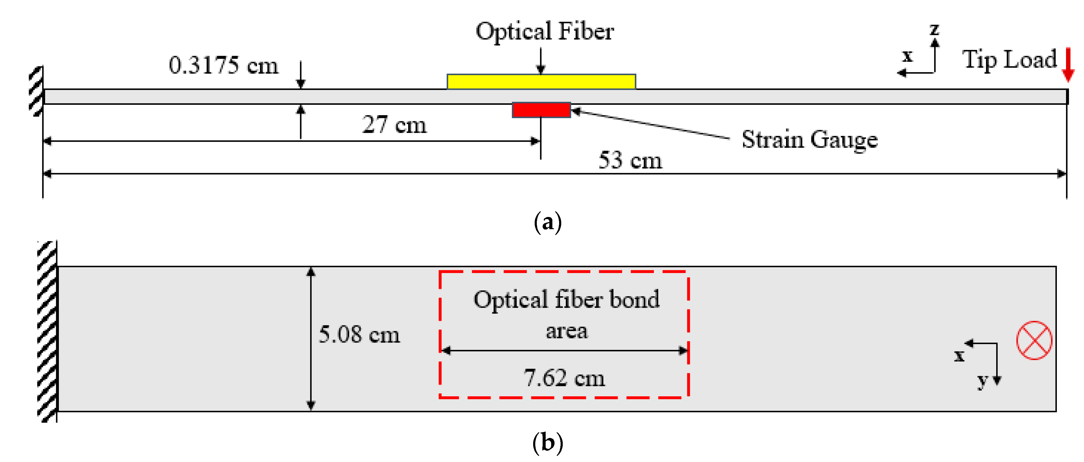
The Euler-Bernoulli beam theory is used for comparison to the optical fiber strains for each cantilever beam. The internal bending moment in the cantilevered beam (Figure 1a) is determined from its free-body diagram (Figure 1b) as
  M = P ( x a ) ,  
where M and P are the internal moment and applied force, respectively. The distance a corresponds to the distance between the end of the applied beam and the applied force.
To estimate the stress σ in the cross-section of the cantilever beam, the flexure formula [11] is used as
  σ = M z I ,  
where z is the coordinate from the neutral axis, I is the moment of inertia, and M is the moment. The maximum stress is obtained when z equals the furthermost distance c from the neutral axis as
  σ m a x = M c I = P ( x a ) ( h 2 ) 1 12 b h 3 = 6 P ( x a ) b h 2  
where b and h are the width and height of the rectangular cross-section, respectively, as shown in Figure 1c. Hooke’s law, with Young’s modulus E, is used to estimate the maximum strain (ε) on the surface of the cantilever beam as
  ε m a x = 1 E σ m a x = 1 E 6 P ( x a ) b h 2 .  

4. Materials and Fabrication

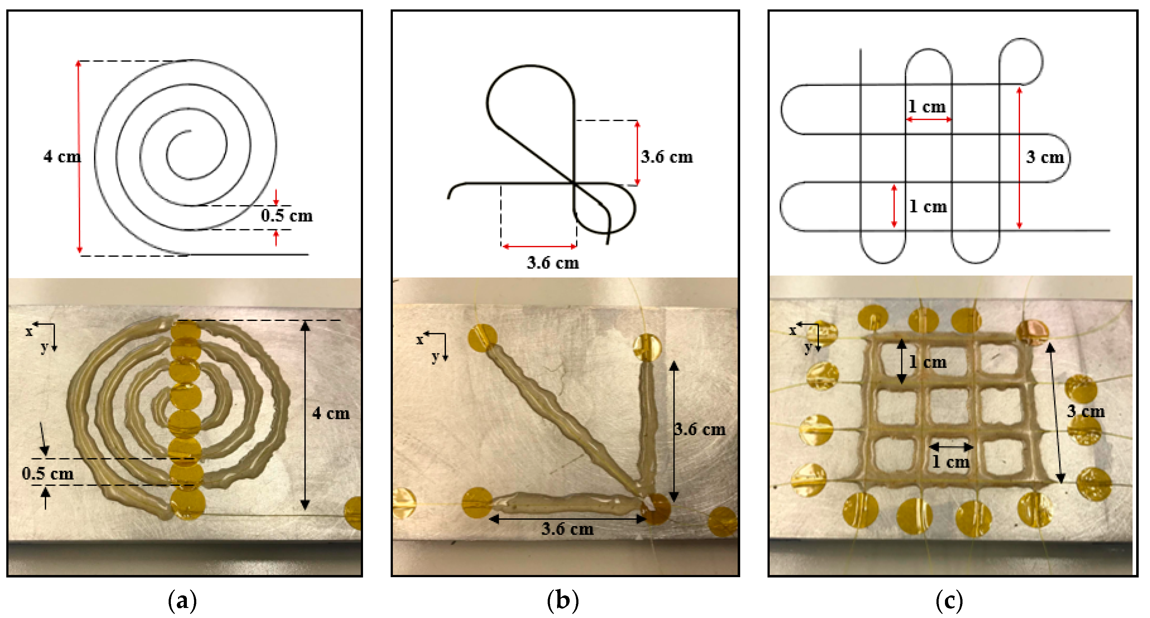
Three cantilever beams were fabricated from a 6061-T6 aluminum plate. The schematic of the aluminum beams and location of the optical fiber and strain gauge are shown in Figure 2a. The spiral, rosette, and grid configurations were bonded to the mid-span and topmost surface of each beam as shown in Figure 2b. The mechanical properties of aluminum, adhesive, and optical fiber are shown in Table 1. An unmodified single mode 155 µm diameter optical fiber with a protective polyimide coating was used as the sensor for all test specimens. The x and y directions correspond to the longitudinal (along the length of each beam) and transverse directions of the aluminum beam, respectively. The dimensions of each optical fiber configuration are shown in Figure 3. The following procedure lists the steps necessary for bonding the optical fiber on three aluminum beams of 5.08 cm width, 53 cm length, and 0.3175 cm thickness.
  • At the mid-span of each beam (Figure 2a), a 7.62 cm by 5.08 cm area was sanded with 600 grit sand paper and cleaned using 99% isopropanol.
  • Light pencil marks were placed on the surface of the aluminum beam away from the bonded area to use as reference points to place the optical fiber.
  • Optical fibers were placed onto each aluminum beam and held in each configuration using Kapton tape.
  • The optical fiber was adjusted until the desired dimensions were accurately reached (shown in Figure 3). This was performed by gently peeling back the Kapton tape to adjust the optical fiber and add a slight pretension to maintain alignment.
  • M-Bond AE-10 resin with GA-2 curing agent was used to adhere the fiber to the surface of the aluminum. This was applied by spreading resin on top of the optical fiber using a thin glass rod. The optical fiber was gently prodded to ensure resin was around the perimeter of the fiber.
  • The adhesive was cured at room temperature for approximately two hours.

5. Experimental Procedure

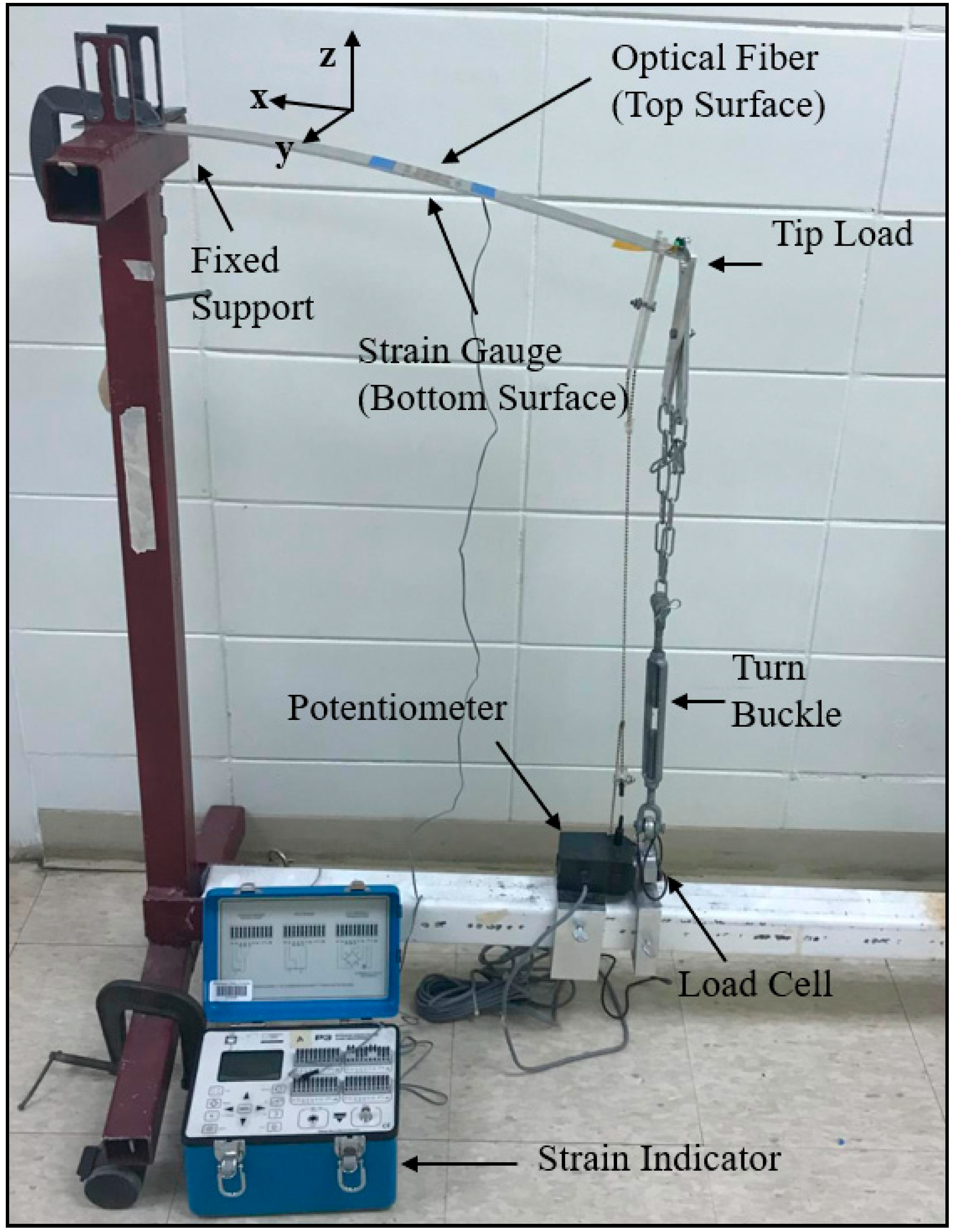
Each beam was clamped to a beam test apparatus as shown in Figure 4. A tip load was applied using a turn-buckle in 4.45 N increments to a maximum of 22.25 N. To remove effects from the mounting/curing processes as well as any deviation from the surface, all measurements from the optical fibers and strain gauges were tared to a zero value prior to loading the cantilevered beams. The applied loading was kept below the proportional limit of the aluminum beam to minimize the amount of hysteresis that may occur during loading and unloading. Research has shown that the hysteresis of plastic optical fibers is significantly reduced when mounted to a metallic substrate [13]. Also, since the optical fiber used in this study has a glass core, the hysteresis effects are regarded to be minimal and within the error of the system. An SML-200 load cell was used to measure the load with a 0.05% accuracy and a maximum capability of 890 N. The surface strains from each optical fiber sensor were measured using the LUNA Technologies ODiSI-B system. Additionally, strains were measured from each strain gauge using the Vishay Micro-Measurements P3 Strain Indicator and Recorder.

6. Results and Discussion

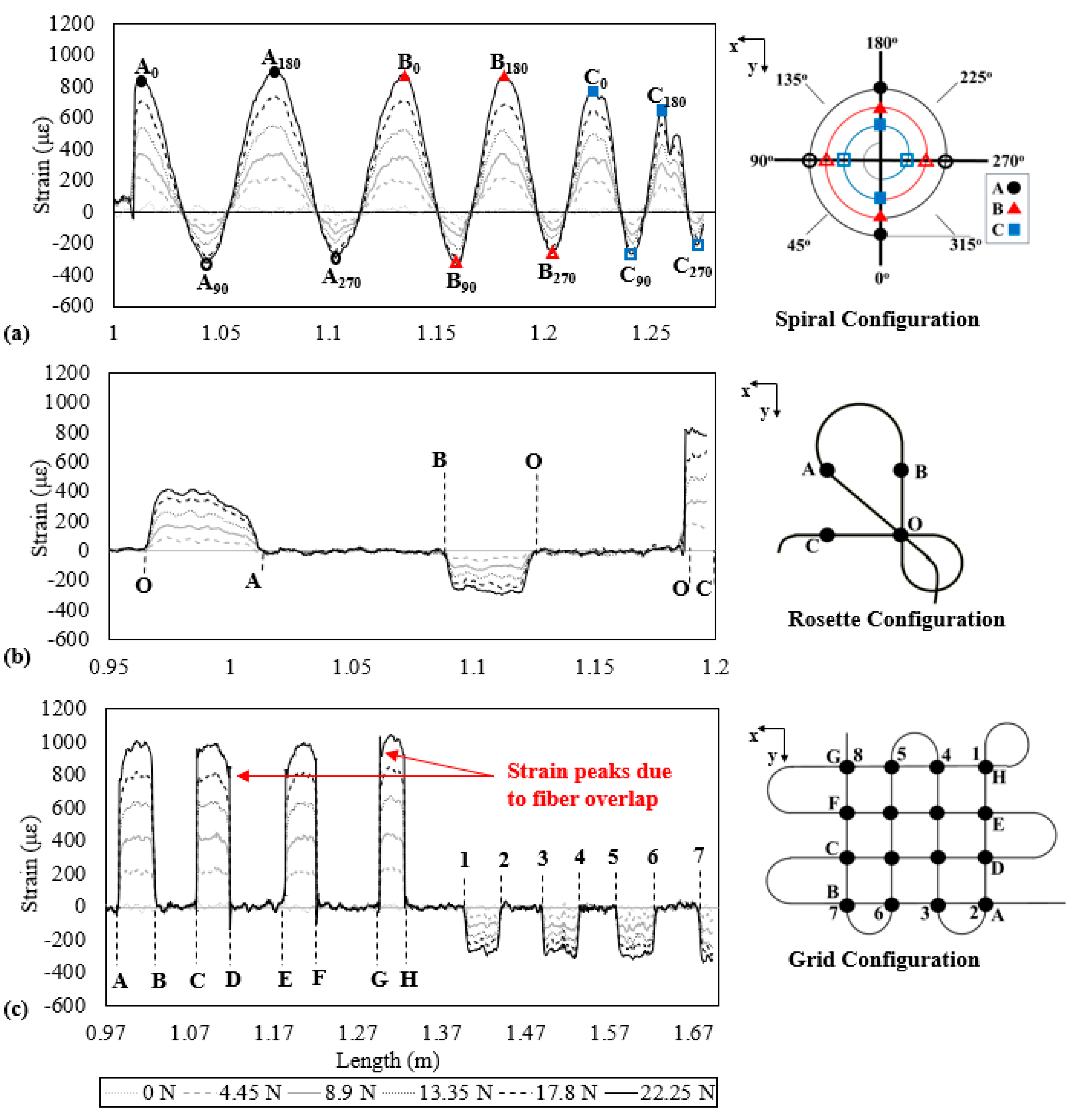
The strain distributions from each optical fiber configuration (spiral, rosette, and grid) are shown in Figure 5. Also, the schematic of each sensor configuration is shown on the right of each figure. The positive longitudinal strains are due to the flexural stresses developed by the applied tip load. In the transverse (y) direction, Poisson’s effect produces negative transverse strains.
The distribution of strain along the optical fiber length for the spiral configuration is shown in Figure 5a. It should be noted that the strain is measured along the axis of the optical fiber. For example, longitudinal strain measurements are obtained at the 0° and 180° locations, whereas transverse strain measurements are obtained from the 90° and 270° locations. The strain has a sinusoidal behavior and the maximum and minimum strain values correspond to the longitudinal (solid symbols) and transverse strain (hollow symbols), respectively. The strain alternates between longitudinal and transverse strain every 90° around the spiral sensor. As the load is increased, the longitudinal (maximum) and transverse (minimum) strain values increase. In addition, the radius along the optical fiber decreases as the measurement location increases due to the optical fiber terminating at the center of the spiral configuration. The sensor is separated into three 360° arc lengths denoted by A, B, and C, which correspond to the outermost (black), center (red), and innermost (blue) regions, respectively. As the load increases, regions A and B show uniform strain distributions. Region C has significantly less longitudinal strain (≈650 µε) at the maximum load when compared to A (≈890 µε) and B (≈875 µε). This may be attributed to the smaller bending radius of C that may have greater loss of light as compared to the straight portions of the optical fiber signals [14], subsequently reducing the strain.
Figure 5b shows the strain distribution for an optical fiber sensor in a rosette configuration. This distribution is characterized by “plateau-like” regions. The segments O A ¯ , B O ¯ , and O C ¯ correspond to the diagonal, transverse, and longitudinal bonded regions of the optical fiber, respectively. The strains from the longitudinal ( O C ¯ ) and transverse ( B O ¯ ) regions are relatively uniform across each plateau. However, the strain measured in O A ¯ decreases as the measurement location increases. This is due to the change in the internal moment along the longitudinal direction of the beam. Furthermore, the slope of strain in section O A ¯ (0.98 m to 1.02 m) changes as the internal bending moment increases from a greater tip load. As expected, the strain is the greatest along the load direction ( O C ¯ ) , followed by the diagonal ( O A ¯ ) and transverse ( B O ¯ ) regions.
The strain distribution from the grid configuration is shown in Figure 5c. The labels A–H correspond to the fiber sections that measure longitudinal strain, whereas labels 1–8 correspond to the sections that measure transverse strain. The magnitude of the strain is relatively uniform along each longitudinal and transverse fiber pass. Near the ends of each bonded region, spikes occur (Points D, G) that may be associated with the overlapped regions of the optical fiber. During bonding of the optical fiber, the transverse regions (1–8) were placed underneath the longitudinal fibers (A–H). This developed a distortion, or change in the radius, of the optical fiber at the ingress and egress of the bonded region as shown in Figure 6. This region may induce strain peaks near the beginning and ends of the optical fiber. The magnitude of strain at these distortions is different because the level of pretension in the optical fiber was not precisely controlled during layup.
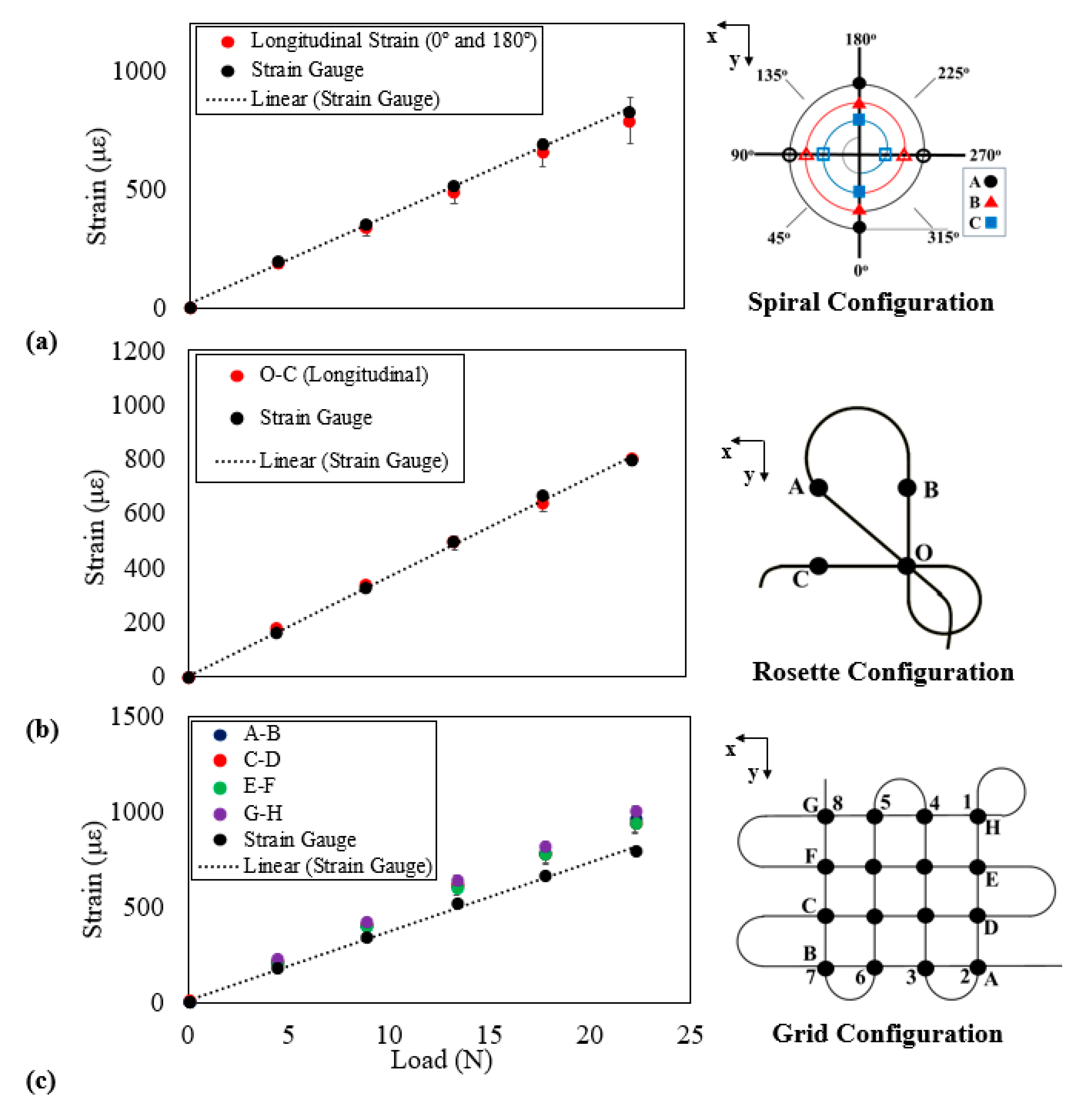
Strain distributions from each optical fiber configuration were compared to uniaxial strain gauge measurements, as shown in Figure 7. It should be noted that the solid markers indicate longitudinal strains whereas the hollow markers indicate transverse strains. Also, since the strains are measured along the axis of the optical fiber, the solid markers on the spiral configuration indicate the longitudinal strain at the 0° and 180° locations for arcs A, B and C. The longitudinal strains for the rosette and grid configurations were calculated as the average strain measured by the optical fiber oriented in the longitudinal (x) direction. For the spiral configuration, the mean longitudinal strains were calculated from points at the 0° and 180° locations on arcs A, B, and C. A linear trend line was fitted to the experimental strain gauge results using a linear least squares method. The strain obtained from the optical fibers is from the nearest location to the strain gauge.
Strains with respect to the applied load for the spiral and rosette configurations are shown in Figure 7a,b, respectively. Both configurations have consistent measurements when compared to the measurements obtained from the strain gauge. As given in Table 2, the average percent difference between the strain gauge and spiral and rosette sensors is about 6%. Some difference between the electrical strain gauges and the optical fiber sensors was expected since the strain gages are offset slightly from the optical fiber locations as they could not be placed directly on the optical fibers. These differences can also be related to the amount of resin and disposition of the fibers. Other factors that may contribute to the difference in the measured strains may be associated with micro-bending effects [15] and residual strain [6]. As mentioned previously, all gauges were tared to a zero value prior to testing.
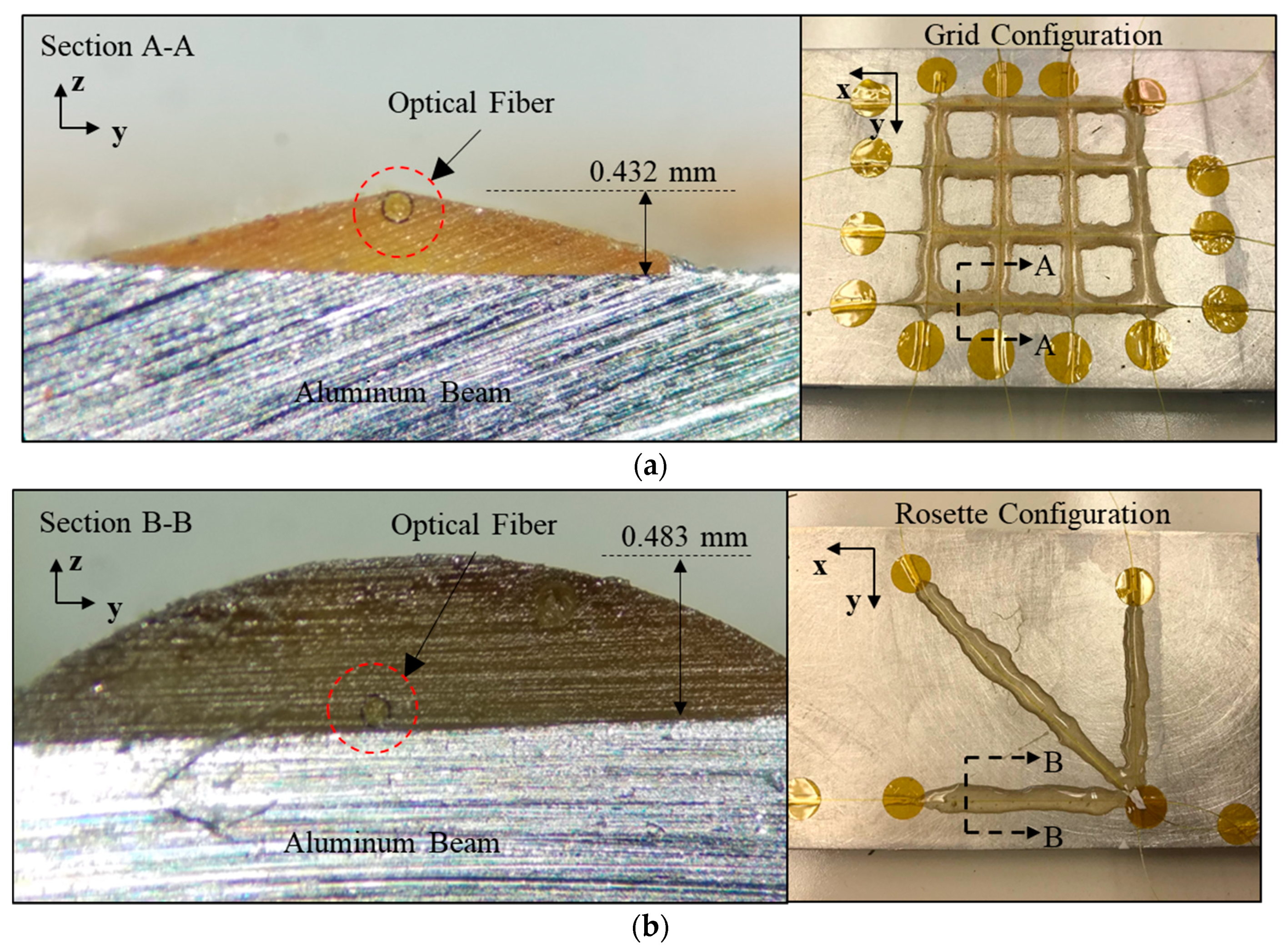
Figure 7c shows the optical grid sensor strains, which deviate from the strain gauge measurements and this difference increases for increasing load. The percent difference in the measured strain from the grid configuration is consistently 20% greater than the strain gauge measurements, as given in Table 2. To investigate probable cause for this constant difference, section cuts were made through the rosette and grid sensors and these cross-sections were observed under a microscope of magnification 6×, as shown in Figure 8. As can be seen, the difference in the strain gauge and grid sensor is primarily due to the optical fiber being offset from the surface of the aluminum beam. The grid sensor is shown to be offset by 0.432 mm (Figure 8a) at the overlap point A-A, whereas the optical fiber in the rosette gage is at the surface (Figure 8b). This indicates that the overlapping of the optical fibers in the grid configuration produces an offset in the disposition of the optical fiber relative to the surface of the aluminum beam. Therefore, a longer length between the overlap points or a correction factor should be used for the grid sensor to obtain accurate strain measurements.
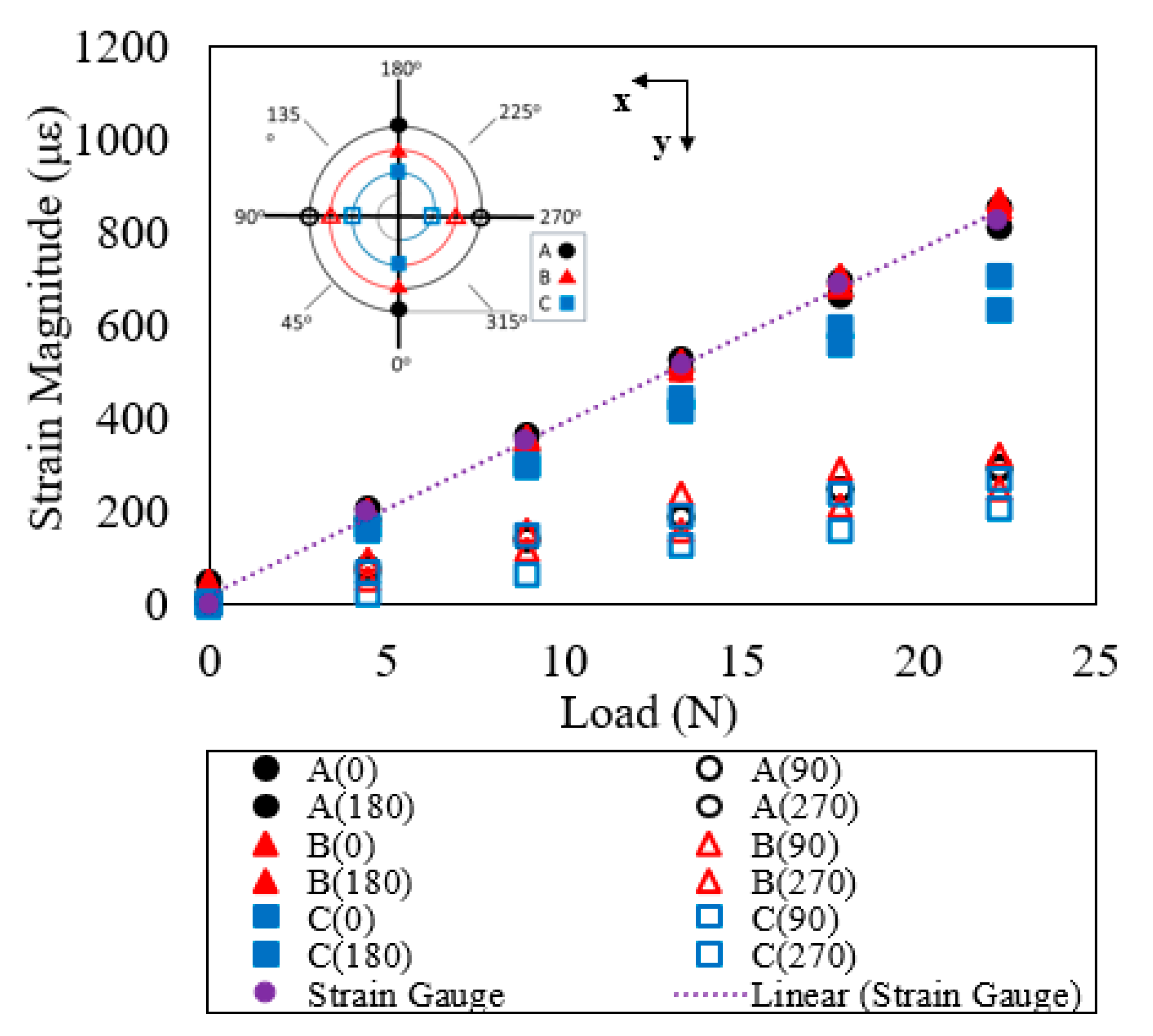
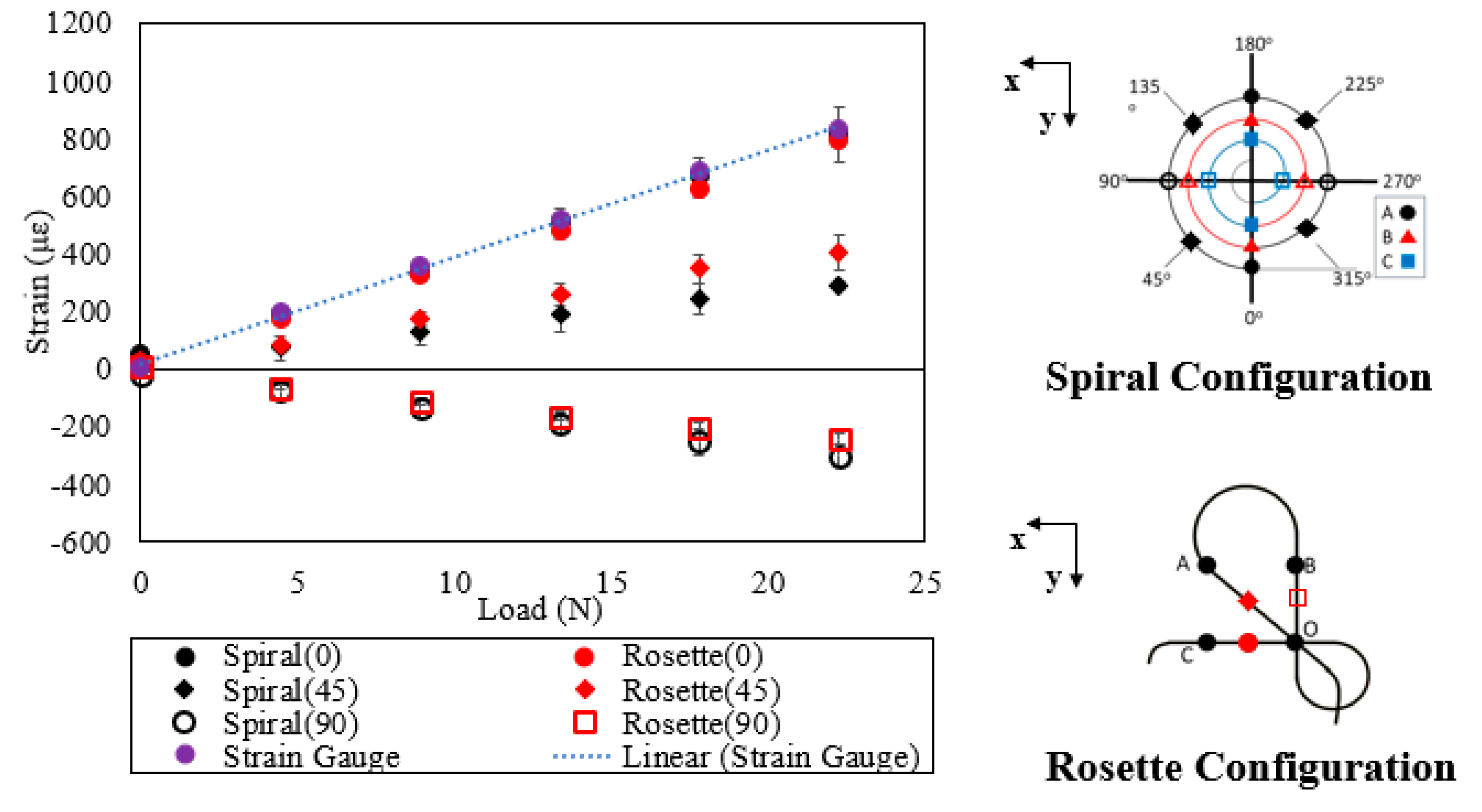
The strains in the longitudinal (0° and 180°) and transverse (90° and 270°) directions with respect to the applied load are shown in Figure 9. The initial reference angle (A0°) is located at the ingress of the optical fiber. As the optical fiber length increases or the fiber radius decreases, the strain measurements decrease because of local bending of the optical fiber. This decrease in the strain is readily seen in region C as compared to region A. In Figure 10, the strain with respect to the applied load is shown for the 0°, 45°, and 90° orientations for the spiral and rosette configurations. Both configurations are relatively consistent in the measurement of strain for the 0° and 90° directions. However, a greater deviation is seen in the measurement of strain for the 45° direction. This may be due to the slight differences in the angle of the optical fiber as compared to the rosette strain gauge.

7. Conclusions

The strain distributions from optical fibers arranged in spiral, rosette, and grid configurations were investigated. Each configuration displays a specific strain distribution pattern. The optical fiber sensor in a spiral configuration shows a sinusoidal strain distribution, whereas a “plateau-like” strain distribution is obtained from the rosette and grid configurations. The spiral and rosette configurations show excellent agreement with strain measurements obtained from traditional strain gauges. The spiral sensor also shows a dependency on the radius of curvature of the fiber. Decreasing the radius of the optical fiber decreases the accuracy of the strain measurement and a minimum radius (r < 1 cm) is required for the spiral sensor. Unlike the spiral and rosette sensors, the grid (lattice) configuration measures strains that are 20% greater than the strain measurements at all applied loads. Observations of images of the cross-section of the beams revealed that this difference is primarily due to the offset of the optical fiber from the beam surface. This offset is caused by the overlap of the fibers in the creation of the grid configuration on the aluminum beam. Therefore, larger grid configurations that allow for longer lengths between transitions may be necessary. Overall, good correlation between the sensors and strain gauge measurements was obtained and the potential to obtain strain distributions from a variety of configurations was demonstrated.

Author Contributions

Conceptualization, R.W.S.; Methodology, R.W.S., D.A.D.; Validation, D.A.D., J.C.W.; Formal Analysis, R.W.S., D.A.D., J.C.W.; Investigation, D.A.D., J.C.W.; Data Curation, D.A.D., J.C.W.; Writing-Original Draft Preparation, D.A.D., J.C.W.; Writing-Review & Editing, R.W.S., D.A.D.; Supervision, R.W.S., D.A.D.; Project Administration, R.W.S., D.A.D.; Funding Acquisition, R.W.S.

Funding

This material is based upon work supported by the National Aeronautics and Space Administration Marshall Space Flight Center under Grant No. NNX16AN40G. This research was also supported by the Office of Research and Economic Development at Mississippi State University through the Undergraduate Research Program.

Conflicts of Interest

The authors declare no conflict of interest.

References

  1. Minakuchi, S.; Takeda, N.; Takeda, S.-I.; Nagao, Y.; Franceschetti, A.; Liu, X. Life cycle monitoring of large-scale CFRP VARTM structure by fiber-optic-based distributed sensing. Compos. Part A Appl. Sci. Manuf. 2011, 42, 669–676. [Google Scholar] [CrossRef]
  2. Grave, J.H.L.; Haheim, M.L.; Echtermeyer, A.T. Measuring changing strain fields in composites with Distributed Fiber-Optic Sensing using the optical backscatter reflectometer. Compos. Part B Eng. 2015, 24, 138–146. [Google Scholar] [CrossRef]
  3. Davis, C.; Knowles, M.; Rajic, N.; Swanton, G. Evaluation of a Distributed Fibre Optic Strain Sensing System for Full-Scale Fatigue Testing. Procedia Struct. Integr. 2016, 2, 3784–3791. [Google Scholar] [CrossRef]
  4. Batte, L.K.; Sullivan, R.W.; Ranatunga, V.; Brown, K. Impact response in polymer composites from embedded optical fibers. J. Compos. Mater. 2018. [Google Scholar] [CrossRef]
  5. Choi, B.-H.; Kwon, I.-B. Strain pattern detection of composite cylinders using optical fibers after low velocity impacts. Compos. Sci. Technol. 2018, 154, 64–75. [Google Scholar] [CrossRef]
  6. Drake, D.; Sullivan, R.W.; Spowart, J. Cure Monitoring of CFRP Composites using Embedded Optical Fibers. In Proceedings of the 56th AIAA Aerospace Science Meeting, AIAA Scitech Forum, Kissimmee, FL, USA, 8–12 January 2018. [Google Scholar]
  7. Meadows, L.; Sullivan, R.W.; Brown, K.; Ranatunga, V.; Vehorn, K.; Olson, S. Distributed optical sensing in composite laminates. J. Strain Anal. Eng. Des. 2017, 52, 410–421. [Google Scholar] [CrossRef]
  8. Gifford, D.K.; Soller, B.J.; Wolfe, M.S.; Froggatt, M.E. Distributed fiber-optic temperature sensing using Rayleigh backscatter. In Proceedings of the 2005 31st European Conference on Optical Communication, ECOC 2005, Glasgow, UK, 25–29 September 2005; pp. 511–512. [Google Scholar]
  9. Kreger, S.T.; Gifford, D.K.; Froggatt, M.E.; Soller, B.J.; Wolfe, M.S. High Resolution Distributed Strain or Temperature Measurements in Single- and Multi-Mode Fiber Using Swept-Wavelength Interferometry. In Proceedings of the Optical Fiber Sensors, Cancun, Mexico, 23–27 October 2006. [Google Scholar]
  10. Soller, B.J.; Wolfe, M.; Froggatt, M.E. Polarization Resolved Measurement of Rayleigh Backscatter in Fiber-Optic Components. In Proceedings of the Optical Fiber Communication Conference and Exposition and The National Fiber Optic Engineers Conference, Anaheim, CA, USA, 6–11 March 2005. [Google Scholar]
  11. Hibbeler, R.C. Mechanics of Materials, 6th ed.; Pearson Prentice Hall: Upper Saddle River, NJ, USA, 2005. [Google Scholar]
  12. Antunes, P.; Domingues, F.; Granada, M.; André, P. Mechanical Properties of Optical Fibers. In Selected Topics on Optical Fiber Technology; Yasin, M., Ed.; InTech: London, UK, 2012; ISBN 978-953-51-0091-1. [Google Scholar] [Green Version]
  13. Abang, A.; Webb, D.J. Influence of mounting on the hysteresis of polymer fiber Bragg grating strain sensors. Opt. Lett. 2013, 38, 1376–1378. [Google Scholar] [CrossRef] [PubMed] [Green Version]
  14. Alexandar, D.; Marijana, F.; Richard, Y.K.F. Principles of deflection-curvature measurement. Meas. Sci. Technol. 2001, 12, 1983. [Google Scholar]
  15. Di, H.; Xin, Y.; Jian, J. Review of optical fiber sensors for deformation measurement. Optik 2018, 168, 703–713. [Google Scholar] [CrossRef]
Figure 1. (a) Cantilevered beam with an applied tip load P and its (b) free-body diagram illustrating the internal bending moment M and shear V and (c) the beam cross-section.
Inventions 03 00067 g001
Figure 2. (a) Side view of cantilever beam and (b) top-down view of cantilever beam.
Inventions 03 00067 g002
Figure 3. Optical fiber sensors in (a) spiral, (b) rosette, and (c) grid configurations.
Inventions 03 00067 g003
Figure 4. Beam testing apparatus.
Inventions 03 00067 g004
Figure 5. Measured strain along optical fiber length for different applied loads (0 N to 22.25 N) for the (a) spiral, (b) rosette, and (c) grid configurations.
Inventions 03 00067 g005
Figure 6. Side view of the aluminum beam with bonded optical fiber in a grid configuration.
Inventions 03 00067 g006
Figure 7. Measured absolute strain from (a) spiral, (b) rosette, and (c) grid configurations compared to the longitudinal strain from the strain gauge.
Inventions 03 00067 g007
Figure 8. Cross-sectional images of aluminum beam showing placement of optical fiber in the (a) grid and (b) rosette configurations.
Inventions 03 00067 g008
Figure 9. Absolute strain for regions A, B, and C within the spiral configuration.
Inventions 03 00067 g009
Figure 10. Strains from the 0°, 45°, and 90° directions for the spiral and rosette configurations.
Inventions 03 00067 g010
Table 1. Mechanical Properties of Aluminum, Adhesive and Optical Fiber.
MaterialModulus of Elasticity (GPa)% Elongation
6061-T6 Aluminum68.912
AE-10 Adhesive3.510
Optical Fiber [12]16.62.5
Table 2. Strain values from the optical fiber (OF) sensors and strain gauges (SG).
Applied Load (N)Longitudinal Strain (με)
4.458.913.3517.822.25
SpiralOF186.8337.7488.8653.5789.2
SG196.0356.0517.0686.0829.0
% Diff4.75.25.54.74.8
RosetteOF172.8335.6492.4636.3797.0
SG158.0323.0493.0662.0791.0
% Diff9.43.90.13.90.8
GridOF212.4407.2614.0785.4957.1
SG175.0338.0510.0655.0798.0
% Diff21.420.520.419.919.9