1. Introduction
Additive manufacturing has transformed prototyping and component production across multiple industries. Among available processes, stereolithography (SLA) [
1] offers superior dimensional accuracy and surface quality, but generates fully cured polymer waste that is difficult to reintegrate into the production cycle.
Unlike thermoplastics used in fused filament fabrication [
2], SLA photopolymer resins are thermosetting materials [
3], meaning they undergo irreversible cross-linking during ultraviolet (UV) curing. As a result, once polymerized, the material cannot be remelted or reshaped, creating a challenge for recycling and sustainable waste management.
In Earth-based applications, mechanical and chemical recycling of SLA waste typically involves grinding or shredding the fully cured components into small fragments, followed by partial dissolution using solvents or chemical depolymerization processes.
A notable terrestrial example of polymer reuse in manufacturing is the Ford [
4]–HP [
5] partnership [
6], which demonstrated the conversion of waste from industrial 3D printing processes into injection-molded automotive components, such as fuel-line clips for the Ford Super Duty F-250 [
7]. In this approach, residual powders and discarded parts from HP’s polymer-based printing systems are pelletized and reprocessed into feedstock suitable for large-scale molding, achieving reduced cost and material weight while maintaining mechanical performance.
However, existing shredding and milling systems are generally gravity-dependent, open to the environment, and optimized for bulk polymer materials rather than high-precision photopolymers. The growing adoption of SLA in engineering, medical, and aerospace applications highlights the need for compact, controlled, and energy-efficient recycling solutions that can recover material for reuse or safe disposal.
In parallel, the concept of in situ manufacturing and recycling in space has gained increasing attention within the framework of sustainable space operations. Additive manufacturing has already been demonstrated in orbit through extrusion-based systems such as NASA’s Zero-G Printer and Redwire’s Additive Manufacturing Facility (AMF) [
8]. However, SLA 3D printing has not yet been implemented in microgravity, primarily due to the complexities of liquid resin handling and curing. In anticipation of its eventual deployment aboard platforms such as the International Space Station (ISS) [
9], the Lunar Gateway [
10], or future lunar surface habitats, supporting technologies for material recovery and reuse must be developed concurrently. A future orbital SLA system would require a closed-loop material management chain, encompassing printing, post-processing, shredding of cured waste, dissolution, and re-formulation of the resin feedstock.
Microgravity introduces additional constraints that render terrestrial shredding methods ineffective. In the absence of gravitational sedimentation, solid fragments do not fall or settle, necessitating forced feeding, confinement, and directed evacuation of material. Furthermore, the lack of natural convection complicates thermal management during cutting and grinding operations, which can lead to local overheating or material adhesion. These challenges require sealed, pressure-controlled mechanical systems capable of both fragmenting the material and ensuring safe particle transport through fluid-assisted mechanisms.
Conventional shredding technologies, including those described in patents such as CN 210646676 U [
11] and US 7,334,748 B2 [
12], rely on gravity-assisted feed mechanisms, open geometries, or multi-stage milling chambers with sieves and rotary cutters. While effective for terrestrial plastics, these systems cannot operate in a vacuum or closed environment, nor can they compensate for the absence of gravitational forces. In contrast, the present invention introduces a dual counter-rotating screw mechanism equipped with carbide cutting inserts and supported by a pressurized inert fluid circuit. This configuration enables the controlled shredding of solid photopolymer resin under both normal gravity and microgravity conditions, ensuring particle confinement and active cooling.
In addition to its applicability in future space laboratories, the system provides tangible benefits for Earth-based additive manufacturing facilities, where it can serve as a high-efficiency, low-energy photopolymer recycling device. The use of carbon dioxide (CO2) as a cryogenic cooling and conveying agent reduces tool temperature, cutting force, and energy consumption while extending tool life and maintaining the integrity of the shredded material. Consequently, this invention represents a key enabling technology for advancing sustainable, closed-loop additive manufacturing, both on Earth and in future extraterrestrial environments.
2. Materials and Methods
Existing shredding and granulation systems used for plastics recycling are dominated by gravity-fed knife granulators/knife mills, where rotating knives shear against a fixed bed knife and the particle size is controlled by a granulation screen (sieve) that retains oversized fragments until further cutting occurs [
13]. In industrial preprocessing chains (e.g., WEEE plastics), representative size-reduction technologies include rotary shear, knife mills, hammer mills, and granulators, with the final particle size commonly adjusted through exchangeable screens/sieves [
14]. By contrast, multi-shaft shredders (single- or dual-shaft) typically use slow-speed, high-torque rotors and shear cutters to break bulky plastics, after which downstream granulation/sieving is often used for size classification [
15,
16]. Designs that employ screw-like elements primarily for fragmentation are less commonly reported in the open literature compared with extrusion/compounding screws; therefore, most established solutions remain optimized for terrestrial gravity-assisted residence and discharge, and are generally not designed as sealed, forced-evacuation systems for reduced-gravity environments.
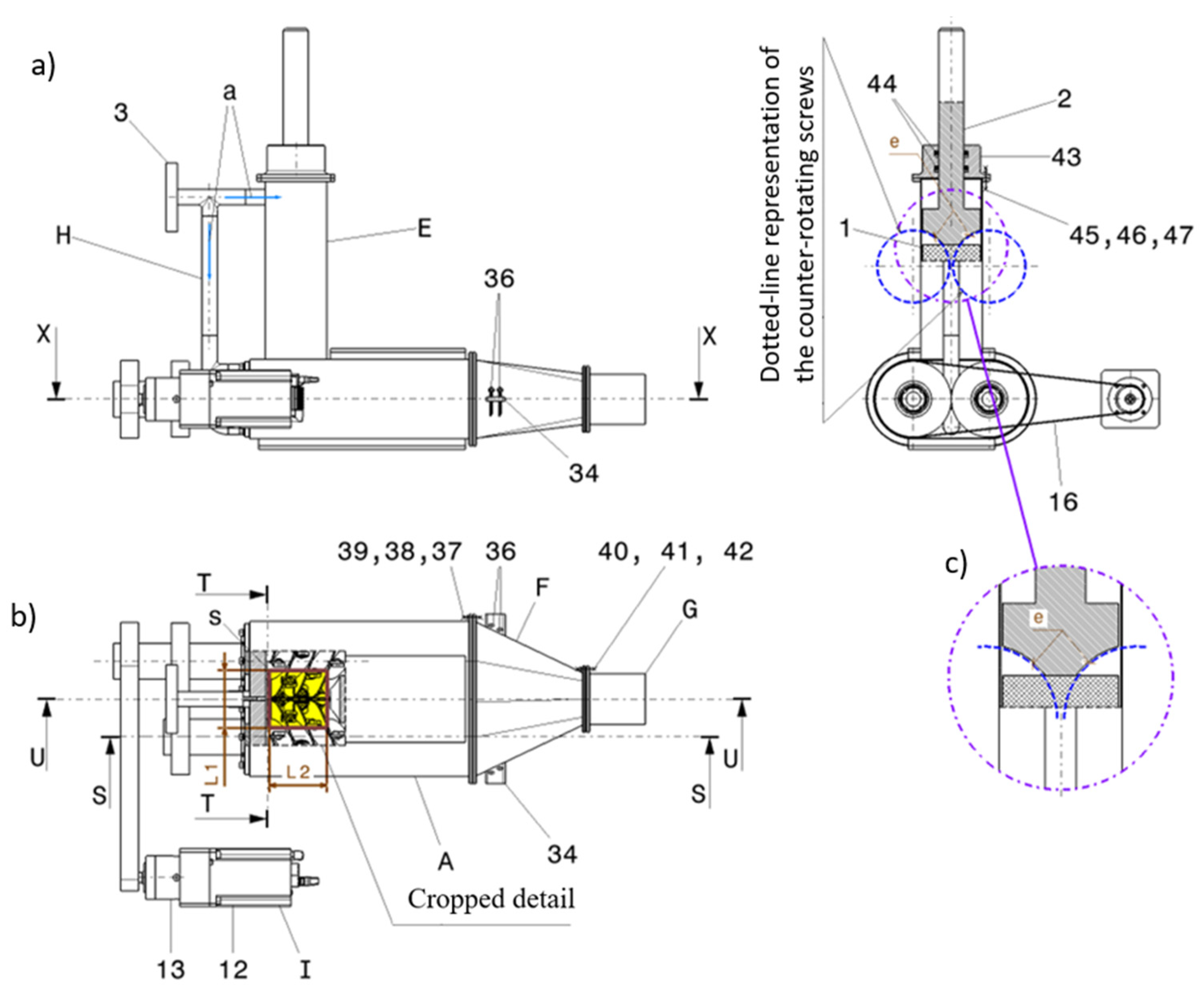
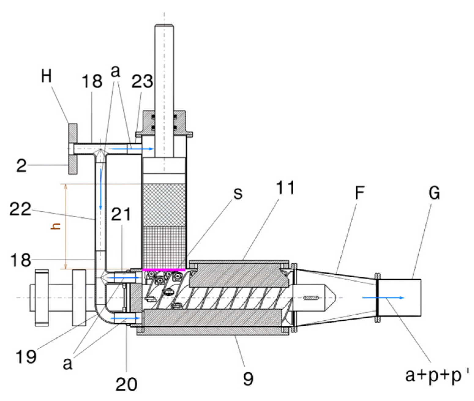
In the context of the present invention, forced feeding and evacuation of material are therefore required to overcome the absence of gravity. To address this, the design introduces active mechanical conveyance of resin fragments and the use of an inert working fluid under controlled pressure, ensuring continuous particle movement, cooling, and containment in a sealed chamber. The overall configuration of the proposed shredder, including its main components and functional arrangement, is illustrated in
Figure 1, which presents general views of the assembly with a detailed inset.
The technical problem addressed by the invention consists of the realization of a compact and hermetically sealed mechanical system, composed of a shredding chamber (A) containing two counter-rotating screw shafts—namely, the left screw-shaft subassembly (B) and the right screw-shaft subassembly (C)—each fitted with carbide cutting inserts (D) mounted at the tip of the screw flanks. The system also includes a sealed feeding hopper (E) that guides the resin parts into the shredding chamber (A), a collector reduction unit (F), a cylindrical outlet (G), and a fluid intake port (H) for the controlled injection of an inert working gas (a), in this case carbon dioxide (CO
2). The assembly is driven by an electric motor system (I) that enables the shredding of solid SLA resin waste (1)—as shown in
Figure 1)—introduced into the sealed hopper (E) and pressed downward by means of a profiled piston (2) into the shredding chamber (A). Inside the chamber, the process begins with chipping and fracture of the material caused by the cutting edges of the carbide inserts (D), after which the fragments are forced along the transport path toward the outlet, assisted by a pressurized inert gas flow (a), here CO
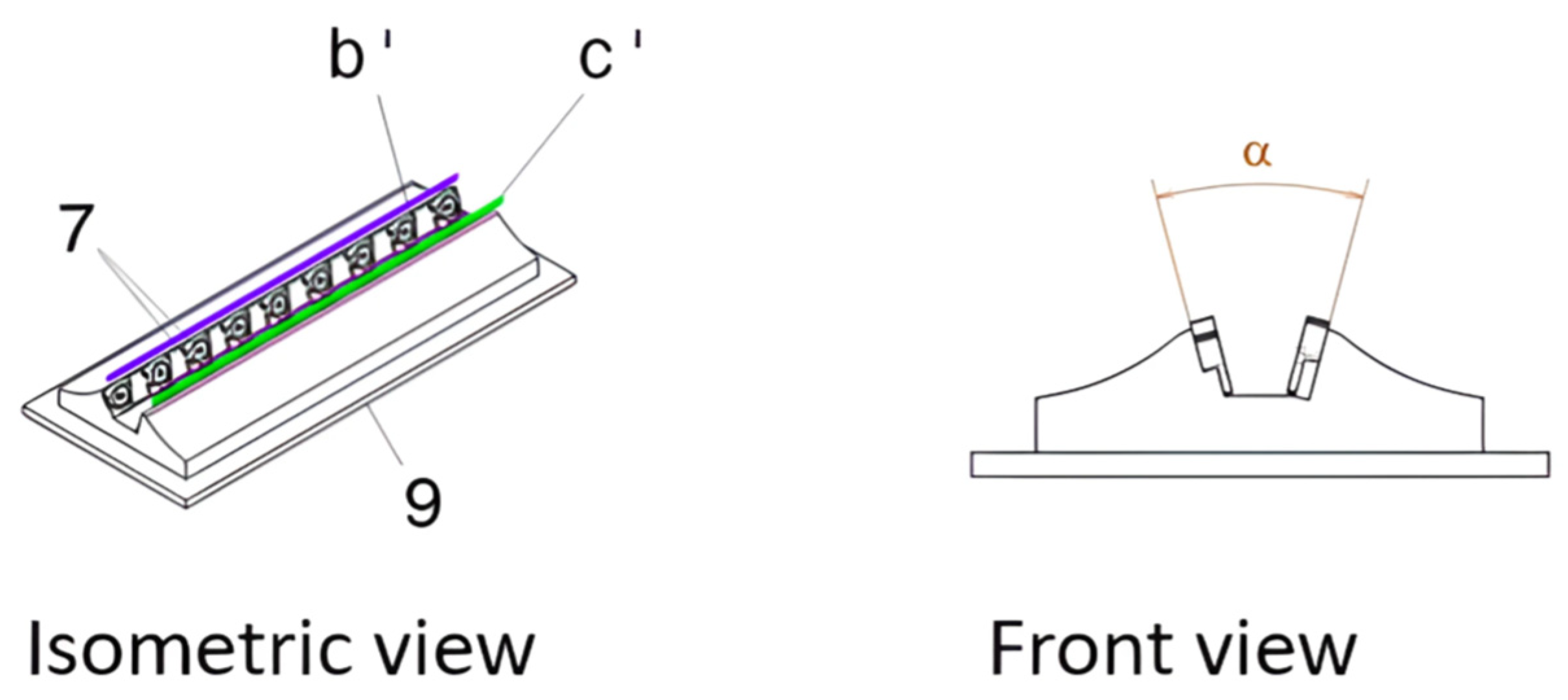
2, which simultaneously serves to cool the cutting process. Along the screw path, two additional rows of stationary cutting blades (b′ and c′) are installed in the central corridor, positioned such that, together with the active blades on the screw flanks (lines b and c), they produce a second-stage fine shredding of any remaining unfragmented resin pieces. Material evacuation is achieved forcibly through the collector reduction unit (F) and the cylindrical outlet (G) via the synchronized action of the two counter-rotating screws, driven by the electric motor system (I), which includes a motor with controller (13) and a speed reducer (14) to ensure sufficient torque and overload protection. The inert gas (a) is introduced under controlled pressure through the intake port (3) of subassembly (H), enabling final discharge, after which the shredded SLA resin fragments (chips) (p) are collected and sorted through other procedures not described in the present invention.
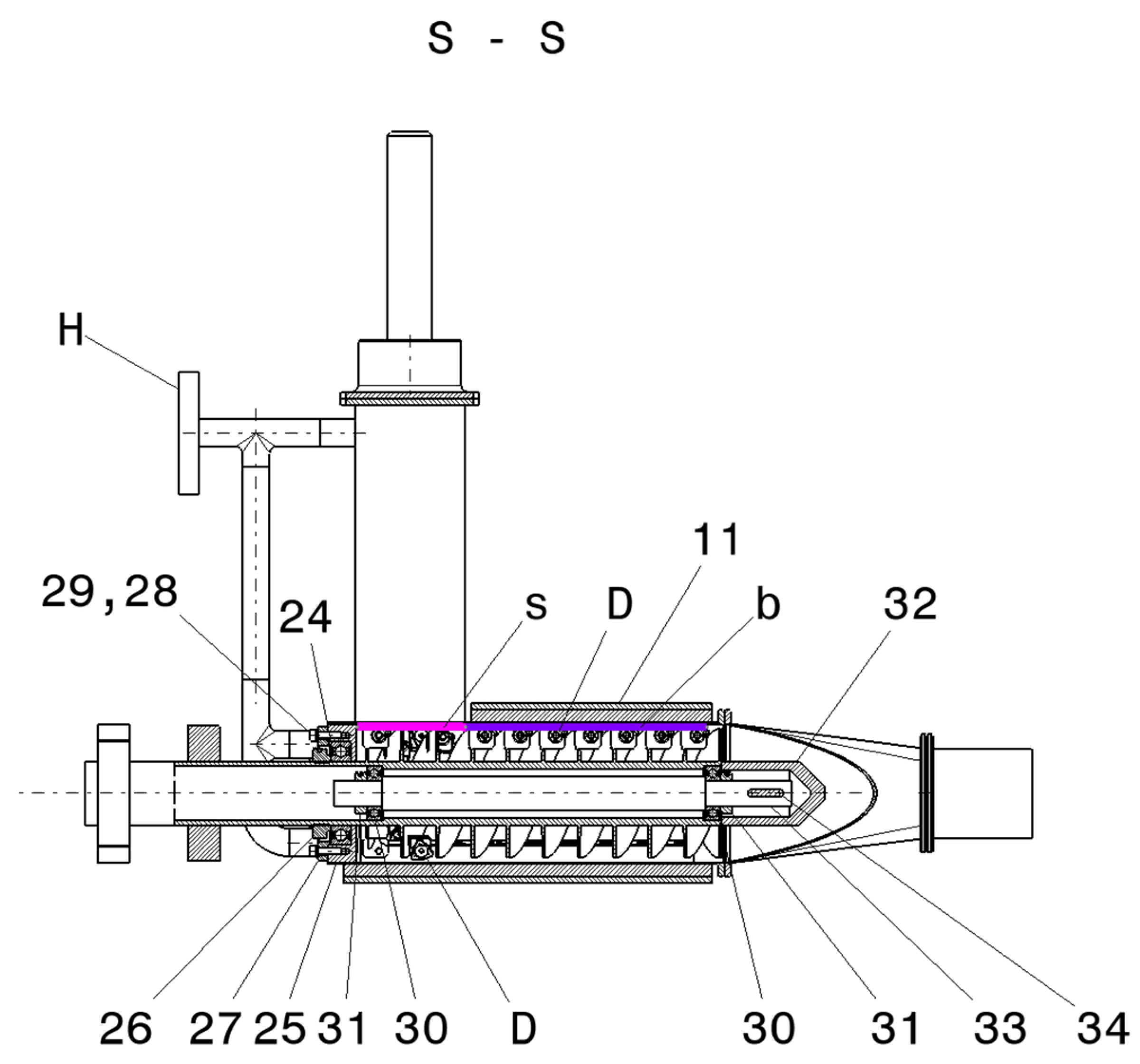
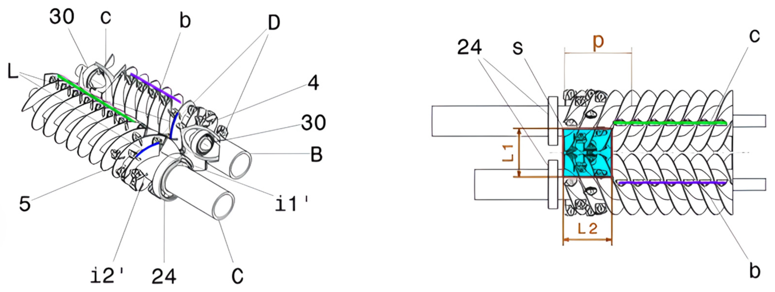
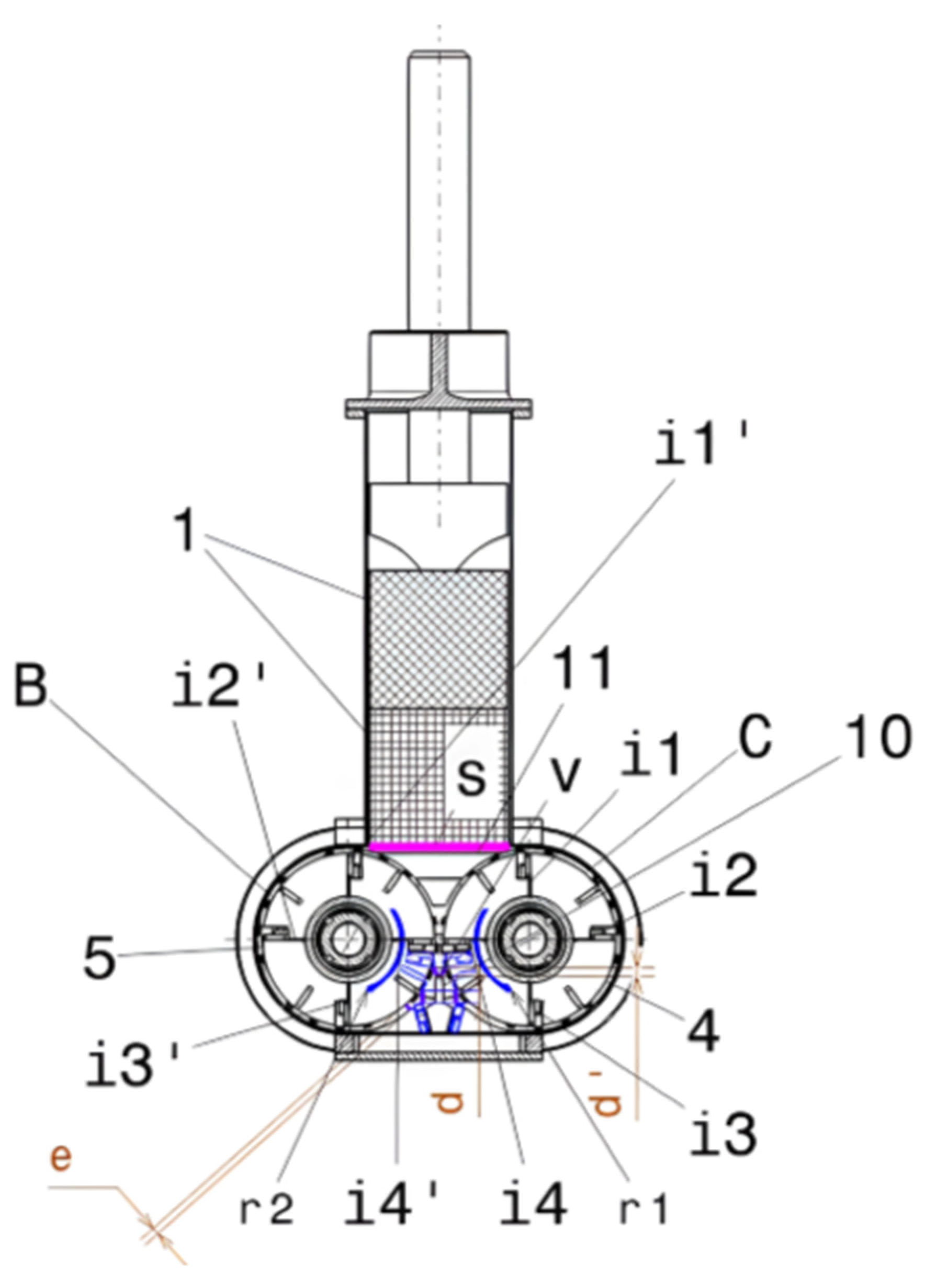
The invention, as illustrated in the accompanying figures, is composed of ten subassemblies (A, B, C, D, E, F, G, H, and I) and several related components. The principal functional role is carried by the two counter-rotating screw shafts (4 and 5) belonging to the left-hand screw-shaft subassembly (B) and the right-hand screw-shaft subassembly (C), as shown in
Figure 2 and
Figure 3.
Each counter-rotating screw has four helical starts—labeled i
1…i
4 for the left screw (4) and i
1′…i
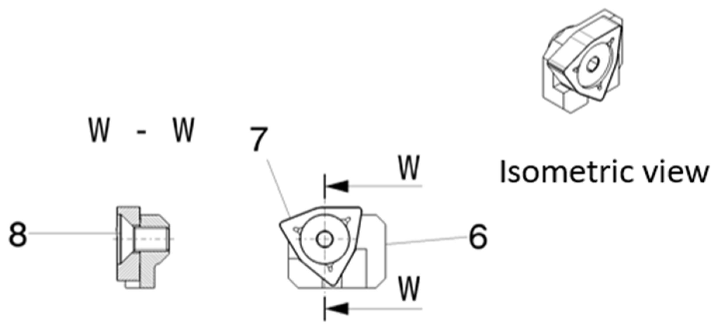
4′ for the right screw (5)—with a defined helical pitch p. On the crest of each helical flank, carbide milling inserts (D) are brazed, consisting of the insert holder (6), the carbide cutter (7), and a recessed-head screw (8) (
Figure 3 and
Figure 4). The inserts are mounted in the first section of each spiral, evenly spaced along the length L, with four inserts per start, totaling sixteen cutters per screw. These are oriented inward toward the centerline, covering a working area s = L
1 × L
2, which corresponds to the outlet cross-section of the sealed feed hopper (E).
Each screw additionally carries seven equally spaced carbide inserts on the outer ridges b and c, also oriented inward relative to the rotation directions r
1 and r
2 (see
Figure 5,
Figure 6 and
Figure 7).
These blades meet a series of stationary cutters fixed to the lower cover (9) along lines b′ and c′, forming a secondary shearing zone at an angle α = 20–30°. This geometry maintains a minimal inter-blade gap d, ensuring fine fragmentation of any remaining uncut resin particles (p′) in the shredding zone (s). The combined rotation of the screws drives the fragments downward and outward toward the collector reduction (F) and cylindrical outlet (G), completing the forced evacuation process (see
Figure 5).
The lower cover (9) is contoured to follow the circular wall of the shredding chamber (A) at a diameter that leaves a small clearance e, preventing accumulation of uncut resin debris (p′) in the lower zone. A profiled deflector piece (10) is mounted on this cover to direct the resin fragments toward the nine evenly spaced cutters (7) arranged along lines b′ and c′. This design provides an additional grinding stage over a minimum gap d′ between the cutter (7) and the tip v of the deflector piece (10). The lower cover also serves a maintenance role, allowing removal of any residual unshredded fragments trapped after operation.
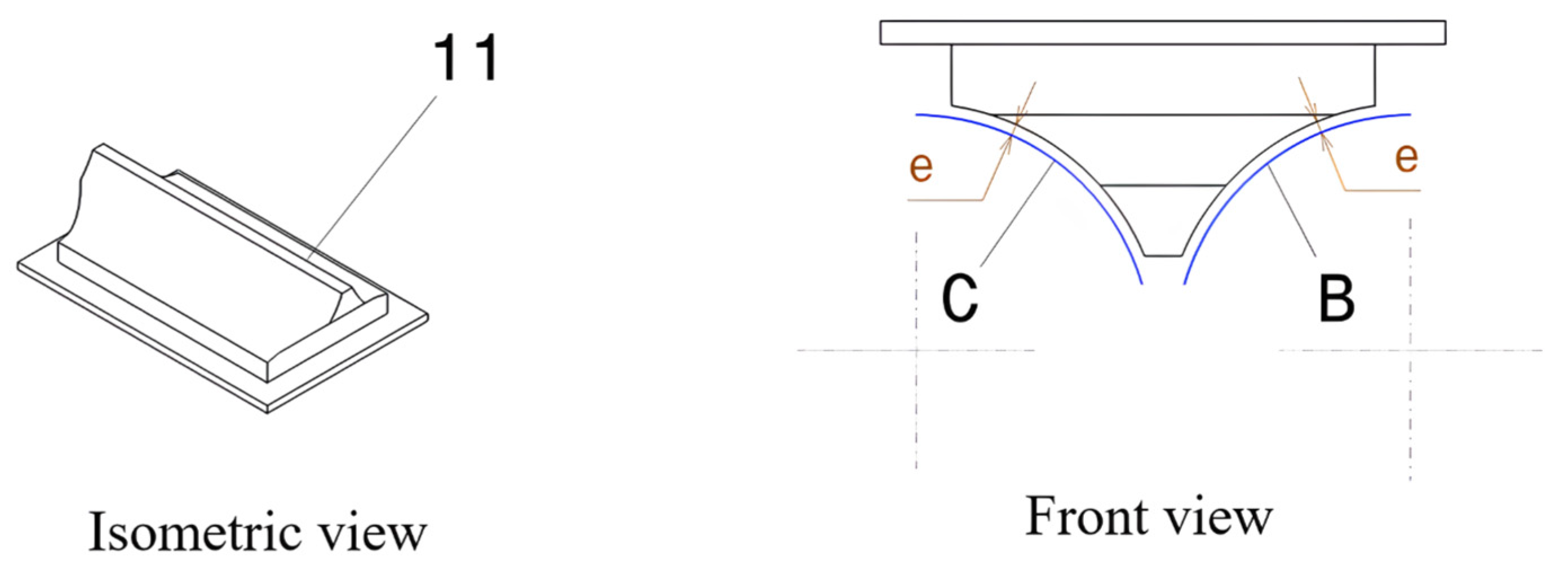
At the upper end of the screw subassemblies (B, C) lies the inspection cover (11) presented in
Figure 8, likewise contoured to the circular chamber wall with the same clearance e. Its purpose is to prevent accumulation of floating debris (p′) in the upper region—particularly relevant in microgravity, where solid particles tend to remain suspended within the chamber. The inspection cover also provides access for maintenance and cleaning.
The sealed feeding hopper (E) has a rectangular-cylindrical geometry with a working area s that accommodates SLA resin residues (1) within a loading volume Va = s × h. The material is pressed downward by a profiled piston (2) whose shape matches the circular contour of the shredding chamber (A), maintaining the clearance e, to avoid contact with the cutters (7) while ensuring maximum volumetric loading of resin fragments.
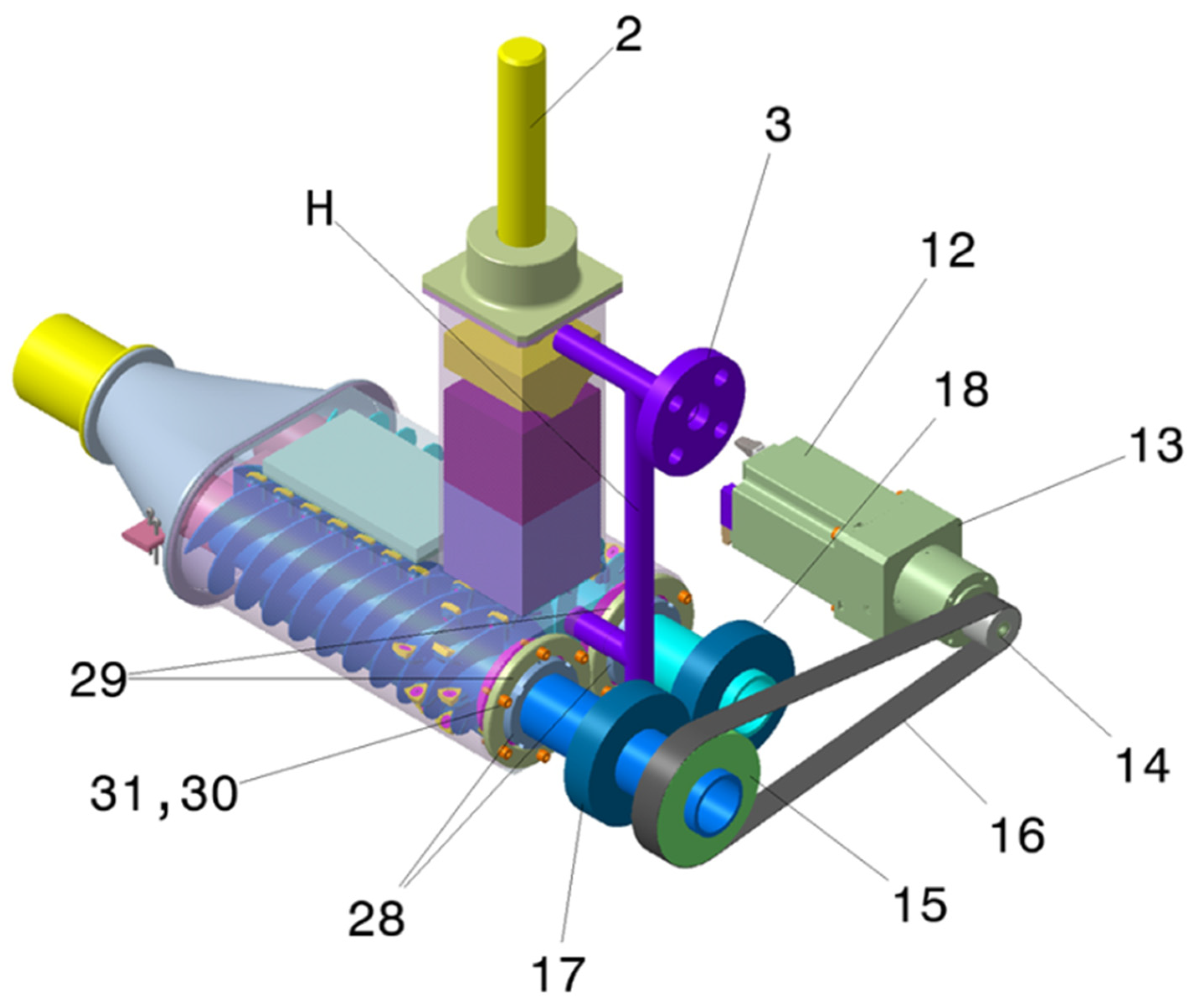
The left and right screw subassemblies (B and C) are powered by the electric drive system (I), which includes a motor with an electronic controller (12) and a speed reducer (13) to provide sufficient torque and overload protection. Motion is transmitted through a motor pinion (14), shaft pinion (15), and toothed drive belt (16). The left screw (5) carries a driven gear (17) that synchronously engages the gear (18) on the right screw (4), ensuring counter-rotation at matched speed (see
Figure 9 and
Figure 10).
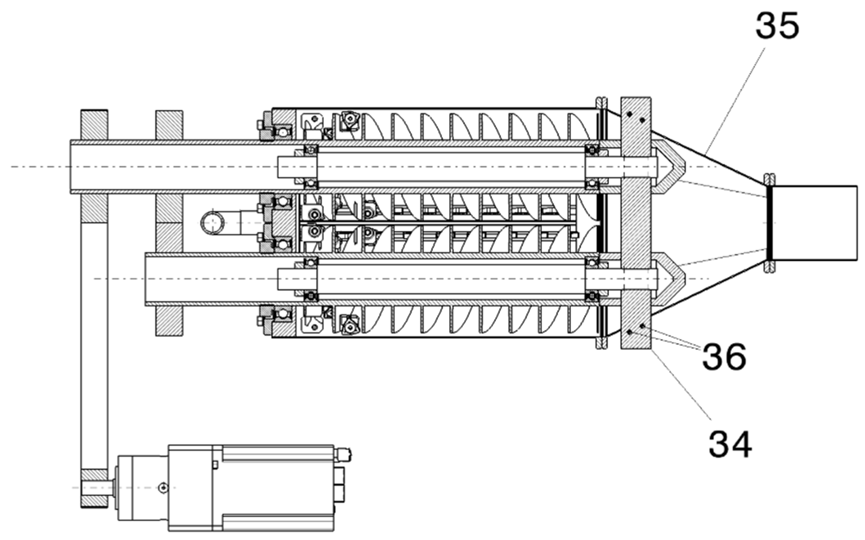
The screw shafts are supported by ball bearings (24) housed in the upstream cover (25) of the shredding chamber, secured with locking nuts (26) and bearing caps (27) fastened with screws and Grower washers (28, 29). Additional ball bearings (30) mounted on the inner shafts (33) are locked with nuts (31) and caps (32) (see
Figure 2). The inner shafts (33) are rigidly fixed to the chamber via a rounded-edge flat bar (34) (see
Figure 10), which passes through both screws and their bearing caps and extends into the collector-reduction housing (35). The flat bar (34) is secured by pins (36) on each side, while the collector reduction (F) is bolted to the shredding chamber (A) using screws, washers, and nuts (37–39), as presented in
Figure 1.
The pressurized inert-gas injection circuit is implemented via the connection flange (2), T-fittings (18), elbow (19), and tubing (20–23). This circuit introduces CO
2 gas at controlled pressure and temperature, both to guide shredded resin particles (p′) toward the collector reduction (F) and cylindrical outlet (G) and to provide active cooling during operation. These assemblies are joined with bolts, washers, and nuts (40–42) (see
Figure 1). Upstream, the sealed hopper (E) is closed by the cover (43) fitted with O-ring seals (44) and fastened by bolts, washers, and nuts (45–47). The fastening details of the lower cover (9), inspection cover (11), and profiled piece (10) are not represented in the schematic views.
Table 1 presents in a more compact form, the list of components and the description of elements.
The invention targets fully cured, cross-linked SLA photopolymers. Because mechanical behavior varies by resin family and post-cure state, fragmentation performance is accommodated through adjustable operating parameters (screw speed, feed force, and cutter clearances d and d′). These settings can be selected to ensure chipping/shearing and secondary re-cutting across a wide range of cured SLA materials.
3. Results
Based on reported data for cryogenic and CO
2-cooled machining [
17,
18,
19,
20], illustrative performance estimates were derived for a representative operating point of the proposed shredder. Although no experimental validation has yet been conducted on the present prototype, these order-of-magnitude calculations support the plausibility of the expected gains in temperature control, cutting force, power consumption, and tool life.
3.1. Cutting-Edge Temperature Reduction (−10 to −30 °C)
In order to quantify the expected benefit of CO2 cooling at the cutting zone, a representative baseline temperature range for dry shredding of cured SLA resin is first assumed. In conventional polymer machining at moderate cutting speeds, the temperature at the tool–chip interface commonly stabilizes around 60–80 °C, depending on cutting speed, feed rate, and tool geometry. In the present shredder, the carbide inserts experience intermittent contact with the resin fragments, but a similar order of magnitude can be reasonably adopted for dry operation, especially given the confined chamber and limited natural convection.
Literature data on CO
2-assisted and cryogenic machining of polymers and composites report reductions in cutting-zone temperature on the order of 10–30 °C relative to dry conditions [
17,
21,
22]. Applying this interval to the assumed baseline, the resulting cutting-edge temperature with CO
2 cooling becomes:
Thus, the effective cutting-edge temperature is expected to lie in the range of 30–70 °C under CO2-assisted shredding, compared to 60–80 °C in dry operation.
This shift has two important implications for the present application:
- 1.
Reduced resin softening and smearing.
Photopolymer resins are known to exhibit a strong temperature dependence of rheological and mechanical behavior, including a reduction in apparent viscosity and progressive softening as temperature increases toward and beyond typical service or transition ranges reported for SLA-type materials (often on the order of 60–70 °C, depending on formulation and post-curing state) [
23,
24,
25]. Under such conditions, increased local compliance at the tool–chip interface can promote smearing and material adhesion on cutting edges. By maintaining the cutting-edge temperature closer to near-ambient conditions (≈30–40 °C), CO
2-assisted cooling reduces the likelihood of thermally induced softening, thereby limiting smear formation on the insert surface and helping to preserve effective cutting-edge geometry
- 2.
Improved chip formation and chip evacuation.
At lower temperatures, the cured SLA resin behaves more like a brittle solid than a viscoelastic one, promoting clean fracture and discrete chip formation instead of ductile tearing. Combined with the momentum of the CO2 jet, this facilitates chip detachment and evacuation from the cutting zone, decreasing the probability of built-up material on the cutters and local blockages in the screw channels.
From a design standpoint, maintaining the cutting zone within 30–70 °C is therefore consistent with the dual objective of protecting tool integrity by avoiding excessive thermal loading, and stabilizing chip morphology so that the downstream dissolution or reprocessing stage receives fragments with more uniform geometry and fewer smeared surfaces.
3.2. Cutting-Force Reduction with CO2 Cooling (−5 to −15%)
To estimate the expected reduction in cutting force, a representative baseline tangential cutting force of approximately 200 N is assumed for dry shredding of fully cured SLA resin, consistent with reported force levels in polymer and polymer-matrix composite machining using carbide tools and scaled to the localized cutting engagement of the present design [
17]. This value is consistent with reported forces in polymer composite milling and low-speed brittle-fracture machining scenarios, scaled to the smaller contact width of the shredder’s cutting edges.
Cryogenic and CO2-assisted machining studies report 5–15% reductions in cutting force, primarily due to the increased brittleness of the material at lower temperatures and the reduction in adhesive–frictional forces at the tool–chip interface.
Applying this percentage range to the assumed baseline:
Therefore, with CO2 cooling, the expected tangential cutting force would lie between 170 and 190 N, compared to 200 N in dry operation. This decrease has several consequences for the shredder’s performance:
- 1.
Lower torque demand.
Cutting torque is approximately proportional to cutting force; thus, a 5–15% force reduction implies a similar percentage reduction in required torque. For a representative screw radius of 20 mm, the torque drops from:
This provides additional safety margin in the drive system and reduces the likelihood of overload events.
- 2.
Reduced vibration and smoother operation.
Lower cutting forces translate to fewer force spikes during chip fracture, leading to more stable screw motion and reduced mechanical wear on shafts, bearings, and couplings.
- 3.
Lower mechanical stress on carbide inserts.
Reduced load diminishes microscopic chipping, extending tool life—consistent with the +10–50% tool life increase reported in cryogenic machining literature.
Overall, a 5–15% reduction in cutting force is entirely consistent with the expected material behavior at reduced temperatures and directly contributes to the overall efficiency of the shredding process.
3.3. Reduction of Electrical Power Consumption (−5 to −12%)
To estimate power savings associated with CO2-assisted shredding, we assume a representative effective cutting power of 400 W during steady-state dry operation. This value includes:
the mechanical work required to fracture the resin,
friction losses on bearings and seals,
internal mixing/transport losses inside the screw channels.
A 5–12% reduction in required power is consistent with the reduction in cutting forces and lower thermal load at the cutters. Applying this range to the baseline 400 W:
Thus, the expected effective electrical power under CO2 cooling lies between 352 and 380 W, compared to 400 W in dry operation. The implications of this reduction are threefold:
- 1.
Energy savings during long-duration use.
For an 8 h operation period:
→ Daily energy savings: 0.16–0.38 kWh
Although modest in terrestrial settings, such savings are significant in power-constrained environments, particularly on orbital platforms.
- 2.
Reduced thermal load inside the sealed chamber.
Lower power consumption means less internal heat generation from friction and cutting. This complements the cooling effect of CO2 and helps maintain chamber temperature stability, especially important in microgravity where natural convection is absent.
- 3.
Extended motor lifetime and lower stress on the drive train.
Operating at 5–12% lower power reduces heating in the motor windings and decreases load on the speed reducer, improving system reliability over long-duration missions.
The estimated savings are therefore consistent with known benefits of CO2 cooling and align with the operational requirements of closed-loop recycling systems envisioned for microgravity environments.
3.4. Increase in Tool Lifetime (+10 to +50%)
The expected 10–50% increase in tool lifetime under CO2-assisted operation can be attributed to two main mechanisms: reduced thermal load and reduced mechanical load on the carbide inserts. Lower cutting-edge temperatures diminish thermal softening of both the resin and the tool substrate, thereby minimizing adhesive wear and edge buildup. Similarly, the 5–15% reduction in cutting force translates directly into fewer high-load fracture events at the tool tip, resulting in slower progression of microchipping and flank wear. Assuming a nominal dry tool life of 100 h, the projected increase corresponds to 110–150 h of effective cutting time under CO2 cooling. Such an extension is significant in closed or remote environments—such as orbital laboratories—where maintenance interventions are costly or infrequent. Quantitative reliability assessment (insert wear progression, adhesion/buildup tendency, and torque/power drift over duty cycles) will be established through dedicated endurance tests in future work.
3.5. Improvements in Chip Morphology and Fragment Uniformity
Lower cutting-zone temperatures also modify the fracture mechanics of cured SLA resin by shifting it from a mildly ductile behavior at elevated temperatures to a more brittle and well-defined fracture regime. As a result, CO2-assisted shredding produces chips that are generally cleaner, more uniform in size, and less prone to smearing or partial melting. In practical terms, the fragment size distribution is expected to narrow toward 1–3 mm, with fewer elongated or fused particles. Reduced adhesion to the cutting edges also ensures more reliable chip evacuation along the screw channels. A potential trade-off is the formation of occasional larger brittle fragments, but the shredder’s secondary cutting stage—defined by the fixed blades on the lower cover—recirculates and reduces these pieces effectively. Overall, the cooling-enhanced chip morphology is advantageous for downstream dissolution or reprocessing steps in a closed-loop photopolymer recycling system.
4. Conclusions
The presented invention introduces a compact, hermetically sealed dual-screw shredder specifically engineered for fragmenting fully cured photopolymer resin in environments where conventional gravity-dependent granulation systems cannot operate. By integrating two counter-rotating screws equipped with carbide cutting inserts, a forced-feed mechanism, and an inert CO2 cooling and evacuation circuit, the device addresses all functional requirements claimed in the patent—namely controlled fragmentation, sealed operation, particle confinement, and compatibility with microgravity.
Performance estimates based on established CO2-assisted machining data indicate that the system can achieve 10–30 °C lower cutting temperatures, 5–15% reductions in cutting force, and 5–12% lower electrical power consumption while extending tool lifetime by approximately 10–50%. These effects collectively improve operational stability, reduce mechanical loading on the drive train, and enable the production of cleaner, more uniform resin fragments suitable for downstream dissolution or reprocessing.
Compared to classical shredding architectures that rely on gravity, open geometries, or sieve-based classification, the proposed design offers significant functional advantages for both terrestrial closed-loop photopolymer recycling and prospective in situ manufacturing systems in orbit or on the lunar surface. By ensuring reliable material flow, thermal control, and sealed operation under microgravity, the invention provides a key enabling technology for future circular-economy workflows in space-based additive manufacturing.
While the present work does not include experimental validation, the disclosed architecture and performance rationale provide a complete and enabling description of the invention; prototype testing and quantitative benchmarking are foreseen as a subsequent development stage following patent protection.
In summary, this patent establishes a novel and robust engineering solution for the controlled fragmentation of cured SLA materials in both Earth and microgravity conditions, filling a technological gap not covered by existing industrial granulators and positioning the device as a foundational component in future photopolymer recycling ecosystems.