Article

A Multi-Ray Channel Modelling Approach to Enhance UAV Communications in Networked Airspace

by
Fawad Ahmad
1,2,
Muhammad Yasir Masood Mirza
2,
Iftikhar Hussain
3 and
Kaleem Arshid
1,4,*
1
Department of Naval, Electrical, Electronic and Telecommunications Engineering (DITEN), University of Genova, 16145 Genova, Italy
2
Department of Electrical Engineering, Capital University of Science and Technology, Islamabad 44000, Pakistan
3
School of Social Sciences, Heriot-Watt University, Edinburgh EH14 4AS, UK
4
System Engineering and Automation Department, Carlos III University of Madrid, 28903 Madrid, Spain
*
Author to whom correspondence should be addressed.
Inventions 2025, 10(4), 51; https://doi.org/10.3390/inventions10040051
Submission received: 19 May 2025 / Revised: 23 June 2025 / Accepted: 24 June 2025 / Published: 1 July 2025

Abstract

In recent years, the use of unmanned aerial vehicles (UAVs), commonly known as drones, has significantly surged across civil, military, and commercial sectors. Ensuring reliable and efficient communication between UAVs and between UAVs and base stations is challenging due to dynamic factors such as altitude, mobility, environmental obstacles, and atmospheric conditions, which existing communication models fail to address fully. This paper presents a multi-ray channel model that captures the complexities of the airspace network, applicable to both ground-to-air (G2A) and air-to-air (A2A) communications to ensure reliability and efficiency within the network. The model outperforms conventional line-of-sight assumptions by integrating multiple rays to reflect the multipath transmission of UAVs. The multi-ray channel model considers UAV flights’ dynamic and 3-D nature and the conditions in which UAVs typically operate, including urban, suburban, and rural environments. A technique that calculates the received power at a target UAV within a networked airspace is also proposed, utilizing the reflective characteristics of UAV surfaces along with the multi-ray channel model. The developed multi-ray channel model further facilitates the characterization and performance evaluation of G2A and A2A communications. Additionally, this paper explores the effects of various factors, such as altitude, the number of UAVs, and the spatial separation between them on the power received by the target UAV. The simulation outcomes are validated by empirical data and existing theoretical models, providing comprehensive insight into the proposed channel modelling technique.

1. Introduction

Unmanned aerial vehicles (UAVs), commonly known as flying vehicles (FVs) or drones, with their versatile capacities and cumulative affordability, are significantly becoming a fundamental part of progressive airspace networks. UAVs have increased significantly and offer favorable solutions to various applications such as surveillance, agricultural monitoring, delivery services, and infrastructure inspection. These drones have proven their efficiency in carrying out various industrial tasks, thereby establishing themselves as versatile tools in the industry. Originally, they were considered for military surveillance and war purposes only; however, due to innovative developments in electronics and communication technologies, UAVs have gone beyond their primary scope and extended their usage across various fields, for instance, oil and gas, agriculture, mining, and beyond. Today, UAVs have significance in commercial, security, entertainment, medical, and telecommunications activities, catalyzing a rise in investment and research to enhance their development for market feasibility. Notable applications, such as Amazon’s Amazon Prime Air [1] and Food Panda’s Panda Fly [2], emphasize the commercial interest in delivery services, highlighting UAVs’ capabilities in this domain. Despite this, the widespread adoption of UAVs encounters challenges in many countries due to security concerns, leading to hesitation in approving commercial operations. Demand is expected to increase as more accommodating regulatory frameworks are established [3,4,5,6].
When multiple UAVs operate in a network, a reliable communication link is required to control and operate their operations. Therefore, safe integration into existing airspace regulations is essential and is closely linked to the sixth generation (6G) standards, IMT-2030 standard (ITU-R M.2160) [6], where electronic devices are organized in an internet-of-things (IoT) network. A stable and reliable internet connection is required to establish a wireless network among devices in areas where the internet facility is unavailable or there is a conventional internet infrastructure. Moreover, when cooperation is essential to complete mutual tasks, such as in various military applications, a “flying things” (The name “flying things” contains systems and devices capable of flight or aerial mobility. This group includes UAVs, drones, quadcopters, aircraft, and other modes of flying vehicles.) network is developed, which works in clusters and performs operations collectively. To complete collaborative tasks effectively, UAVs may develop an ad hoc network, emphasizing their capacity to improve network performance in multipath communication settings. However, the understanding of their capability to establish reliable, high-bandwidth, and low-latency connections is considerably delayed by the constraints of existing communication systems between UAVs and between UAVs and their base stations. The dynamic operational environment of UAVs, revealed by their movement and varying altitudes, introduces complicated challenges in channel modelling and is critical for designing and optimizing communication systems [6].
This paper aims to explore the dynamics of UAV communication, investigate the impact of multipath interference on network efficiency, and propose opportunities for improved operating reliability across various application fields. Traditional channel models, primarily designed for terrestrial communications, rely on the line-of-sight (LoS) signal component and may not accurately represent scenarios where multiple UAVs operate in close proximity. These models often fail to capture the properties of both ground-to-air (G2A) and air-to-air (A2A) communications links, the shadowing effects of UAVs, and their 3-D mobility properties. Additionally, they may not accurately represent scenarios where multiple UAVs are operational in proximity. Therefore, there is a need for an advanced channel modelling approach that encapsulates the complexities of the network in the airspace and improves the reliability and efficiency of UAV communications. This paper proposes a multi-ray channel model applicable to G2A and A2A communications within a networked airspace. The model performs ahead of the conventional LoS assumptions by integrating multiple rays to reflect the multipath transmission produced by UAV actions, such as reflections, detours, and scattering in the environment, and enables accurate estimates of signal intensity, reliability, and quality over the distinct operating scenarios. The multi-ray channel model considers UAV flights’ dynamic and 3-D nature alongside the conditions where UAVs normally operate, such as urban, suburban, and rural. An approach is also introduced to calculate the received power on the target UAV, utilizing the reflective properties of UAV surfaces combined with the multi-ray channel model. The developed multi-ray channel model further facilitates the characterization and performance evaluation of G2A and A2A communications. Additionally, this paper examines the effects of various factors, such as altitude, the number of UAVs, and their spatial separation on the power received by the target UAV. This paper makes the following key contributions:
  • A novel multi-ray channel model is proposed to capture the complexities of airspace networks accurately. This model applies to G2A and A2A communications and is utilized for channel characterization and performance analysis of these communication links.
  • A method for determining the power received at the target UAV is presented. It integrates the reflective properties of UAV surfaces into the multi-ray channel model.
  • This paper explores how key factors—like altitude, the number of UAVs, and spatial separation—affect the power the target UAV receives, offering essential insights into the dynamics of airspace networks.
  • A thorough review of current research on networks of aerial vehicles in multipath settings is performed, accompanied by essential critique and commentary as needed.
By developing UAV communication channel models, our work aims to facilitate the design of robust and efficient systems, paving the way for integrating UAVs into the future of networked airspace.
In the following sections, the detailed literature is presented in Section 2. Section 3 delves into the theoretical foundations of the proposed channel model, describing the methodology adopted for its development. Section 4 presents the experiments and results of the simulation designed to validate its accuracy and effectiveness. Finally, the conclusion is presented in Section 5.

2. Literature Review

The multipath phenomenon is a crucial factor that compromises the performance of communication links in realistic radio communication scenarios. In the context of air-to-ground (A2G) communication, researchers focus on understanding how multipath propagation affects the connection between UAVs and ground base stations (BS) to improve the performance of these links. In this regard, various studies have been conducted to analyze the impact of various propagation parameters on the performance of communication links. In [7], a comprehensive study was conducted on both analytical and empirical models for G2A and A2A UAV communications. These models, previously explored extensively for satellite links and terrestrial cellular networks, were thoroughly reviewed in [8]. Additionally, a few hybrid aeronautical channel models were characterized in [7]. Since then, numerous channel models reported in the literature for G2A/A2G and A2A communication links have emerged. Therefore, existing research has been organized into two primary categories: analytical and simulation-based studies, and measurement-based studies.

2.1. Analytical and Simulation-Based Studies

The existence of a multipath phenomenon can limit the performance of a wireless communication system if not properly managed. Simulation-based modelling approaches are used when practical experiments are not feasible to characterize the multipath channel environment. Most researchers have focused their efforts on drones or flying vehicles, using simulation or measurement campaigns that involve only a few drones, typically one or two. Ray tracing, which effectively predicts radio channel propagation, can be used as an alternative to physical measurements when suitable 3D maps are available [9,10]. Research articles have supported the use of ray-tracing simulation approaches to investigate the characteristics of communication links between UAVs and base stations. The literature also reveals several analytical and simulation-based models that employ various channel parameters, which this section discusses.
In A2G and A2A communications, the phenomenon of radio wave propagation is significantly influenced by various obstacles within the channel and can vary randomly over time. These sudden changes frequently stem from the movement of the transmitter, receiver, and the mediating environment. A propagating environment dense with scatterers and obstructions, such as urban areas, normally exhibits lower received signal strength indicators (RSSI) at the receiver side compared to less obstructed settings [10,11]. RSSI is considered an important metric for assessing the quality of communication links. RSSI measures the power level at the receiver side when a signal travels from the transmitter to the receiver. Therefore, numerous studies have been carried out to investigate the effect of the propagation environment on the received power. Simulations across diverse scenarios, including urban [11,12,13], suburban [14,15], hilly [16,17], and rural [18], as well as built-up [19], help to analyze various critical factors and parameters to accomplish realistic channel models [20]. Moreover, limited research has focused on environments such as hilly terrains, forests, dense urban areas, and overseas places, aiming to improve our understanding of these unique settings [21,22,23,24,25,26].
Researchers have implemented several models to characterize the channel behavior in certain scenarios, including analytical-based models. These models mostly use assumptions and parameters to characterize the channel behavior and are based on mathematical equations that estimate the dynamics of radio wave propagation. The two-ray model [19,27], which contains a LoS component and a single ground-reflected component, was primarily used for channel modelling. This model was further extended to a three-ray model [21]. The two-ray model is extended regarding elevation angle to formulate a closed-form expression for path loss prediction in the A2G communication channel, assuming a single reflected ray from the ground surface [27]. Additionally, comprehensive discussions of analytical models can be acquired in the broad literature, and a few of them are [28,29,30,31,32,33,34].
The elevation angle and receiver height are the key factors influencing the path loss exponent [34]. In the near future, UAVs will be used for commercial services and sustainable urban development control at very low altitudes [34]. At these altitudes, the behavior of A2G communication links deviates considerably from traditional A2G models due to reflection, diffraction, and scattering caused by nearby entities [35]. Furthermore, in common A2G communication, as the altitude of a UAV increases, the number of multipath components decreases. At higher elevations, nearly all reflected rays are negligible, leaving only the LoS component [36]. But, at these higher altitudes, the probability of interference [37] increases, which can be relieved by beam-forming methods throughout multi-UAV operations [38]. UAVs are typically classified based on altitude into (i) higher altitude platform (HAP) [39,40] and (ii) lower altitude platform (LAP) [41,42]. Detailed discussions on channel models for low-altitude UAVs are available in [43]. To explore the effect of altitudes on received power, simulations were performed at various heights ranging from 0 to 40 m [44], 0 to 100 m [18], 2 to 75 m [45], and 50 to 140 m [13]. The literature also proposes several altitude-dependent [46] and elevation-angle-based [46,47] channel models.
In addition to ray tracing and analytical channel modelling, geometrical channel modelling is another important technique. This method models radio channels by positing random scatterers within a defined geometrical shape between the transmitter and receiver [48]. In a research study [49], a geometry-based analytical multipath propagation model to analyze channel behavior in hilly terrains is discussed and validated through ray tracing simulations. The results showed that the model established more accurate results than ray tracing and two-ray models. The study also highlighted the impact of elevation on the received power. However, the model presumed that the path lengths of reflected components are equal to those of the LoS components, efficiently simulating a pure LoS propagation environment and thus neglecting the effect of multipath signal. In another study [50], the geometry-based model was proposed considering millimeter waves; this study mainly considered the LoS probability but did not investigate the received power of the signal.
Currently, UAVs are utilized in swarms [51] to perform several operations. Quite a few algorithms have been developed and examined through simulations [52,53] to assist this. However, there are only a few simulation tools [54] available, which limits improved research in the UAV swarms field, although several studies have already been conducted considering the multi-UAV operations [55]. In [56], the authors established a free space model for UAV swarms at variable altitudes ranging from 10 m to 50 m and at 400 MHz frequency. This model anticipated that transmitting and receiving drones at the same height is impractical since the altitudes of the drones can vary. Furthermore, the results of ray-tracing simulations were not successfully validated with the measured data. To address these shortcomings, another study [57] investigated the impact of multipath components in scenarios where multiple aircraft were considered in the air with a ground-based transmitter. This study developed a channel model for the received power in the G2A communication link. Moreover, it calculated the time delay as well for the multipath components. However, the model was ineffective at the same altitude as the aircraft flying and does not reflect the inconsistent altitudes; the aircraft typically operates during flight.
Table 1 presents a comparative literature review of current analytical and simulation-based studies. It is apparent from the table that nearly all existing analytical models rely solely on LoS links or lack analytical expressions that incorporate multiple rays in their formulations.

2.2. Measurement-Based Studies

The accuracy of channel models derived from analytical methods frequently does not meet expectations, as these models are based on assumptions that overlook actual conditions. As a result, the actual performance of radio channel communication systems can differ significantly. To enhance a channel model’s effectiveness, field measurements are essential. Consequently, various measurement operations are conducted in different scenarios to grasp the true behavior of radio transmission in G2A and A2A communication systems.
The authors in [58,59,60] conducted a comprehensive literature review on A2G channel modeling for UAV communication systems using data from measurement campaigns. They examined small-scale and large-scale fading channel models, highlighting deficiencies and suggesting future research directions. Additionally, the authors assessed various parameters, including elevation, propagation environment, channel statistics, link distance, and path loss.
In [61], a channel propagation model was presented through a campaign at Tsinghua University focusing on UAV communication systems in urban environments. The campaign concentrated on numerous path loss model parameters useful for long-term predictions. However, the channel impulse response was considered only in LoS situations. The research [61] investigated different propagation parameters comprising multipath components that affect channel impulse response across rural, urban, and industrial settings at low altitudes ranging from 0 m to 40 m. The author in [62] reported that the A2G radio channels were indicated at 970 MHz and 5 GHz carrier frequencies in nearby urban and hilly areas. Nevertheless, the UAV altitudes were not identified. In [63], the analysis of the A2G channel included various parameters such as geometry, radius, and drone height. LoS and non-line of sight (NLoS) signal conditions were considered for accurate path loss calculations, with average loss added to free space propagation in a practical path loss model. The study also indicated the probability of having both LoS and NLoS links for improved precision in path loss estimations. Research reported in [64] examined the use of drones as aerial user equipment (AUE) and aerial base stations (ABSs). In [65], measurement campaigns are shown in several scenarios, such as urban, suburban, and rural areas, to characterize significant fading in the A2G communication channel. The measurements were taken at altitudes ranging from 50 m to 950 m and horizontal distances up to 70 km at carrier frequencies of 785 MHz and 2160 GHz. The authors in this research did not consider NLoS links or small-scale fading and are limited to high-altitude flights. This study covered high-altitude flights only. The studies [66,67,68] reported on measurement campaigns in rural areas to assess the elevation and azimuth arrival (EoA/AoA) of multipath components (MPCs) at a 3.5 GHz carrier frequency across altitudes ranging from 50 m to 350 m and horizontal distances up to 300 m.
An altitude-dependent model was proposed in [68] to estimate path loss in LoS and NLoS scenarios at the rate of 1 GHZ and 4 GHz, respectively. Additionally, several channel factors, including shadowing, small-scale fading, and large-scale fading, were investigated, which were limited to low-altitude data; however, the high-altitude measurements were not studied. The authors in [69] calculated the path loss on LoS and NLoS scenarios, considering various frequency bands, where the impacts and altitude on path loss were estimated. However, the measurements were only performed in an environment consisting of trees and bushes. In [70], different target frequencies such as 1 GHz, 4 GHz, 12 GHz, and 24 GHz were used to execute A2G radio channel measurement, and crucial channel parameters were thoroughly inspected using the measurement data. A 3D multiple input multiple output (MIMO) channel for A2G UAV communication is described in [71]. For the non-stationary channel model, an algorithm known as a novel angular estimation algorithm was proposed to estimate different angular parameters, including the elevation angle of departure (EAoD), the real-time azimuth angle of departure (AAoD), the elevation angle of arrival (EAoA), and the azimuth angle of arrival (AAoA). Additionally, several channel characteristics were also analyzed. The study [72] examined the delayed spread of multipath channels for terrestrial and above-sea environments at the rate of 5 GHz. Additionally, the multipath components were analyzed in [73] at the frequency of 3.5 GHz, and on altitude settings ranging from 50 m to 300 m, while the received power was not investigated.
The authors in [66] described several measurement campaigns piloted in a suburban area at different lower altitudes via a medium-sized UAV to examine the impact of different parameters, such as UAV height, distance, and elevation angle, on the A2G channel. Among these parameters, the height was the most effective factor affecting the channel properties. The path loss exponent was determined based on measurements performed at various altitudes. In addition to this, a height-dependent model was also presented. In [74], a channel model was purported to portray the actions of the signal intensity received. This is achieved by accounting for the effects of shadowing and mobility to reduce the signal processing complexity without affecting the channel’s performance. This study used the empirical data obtained from the measurement campaign to validate the model outcomes. The measurement campaigns described in [75] were performed in multiple suburban areas to characterize radio channels using small-size UAVs over low altitudes, considering the following parameters: path loss, shadow fading, Doppler spread, and RMS delay. In [69], an analytical path loss model was introduced for different scenarios, where the antenna gain without an obstacle in the elevation plane determines the received power of the LoS component. The effects of different parameters, including path loss, RMS-DS, multipath components, and k factors, were examined for LoS and NLoS scenarios via measurement campaigns accomplished in open fields at frequency rates ranging from 3.1 GHz to 4.8 GHz. The path loss measures, and ray tracing simulation results were compared to validate the model. In [76], the authors performed measurement campaigns in various scenarios, including grass, soil, and rubber floor, to characterize the path loss and further investigate the impact of ground reflection for different altitudes. Furthermore, to reveal the path loss in A2A communication links, the authors recommended analytical models such as the air transmitter receiver (A2AT-R) and a modified long-distance model. The authors only considered a single reflected ray, which is not a realistic approach to measuring the received power in multipath environments. Moreover, related work is also conducted in [77,78]
In Table 2, a comprehensive literature review compares various measurement methods used in A2G and A2A communication contexts. Most research studies focus on measurement operations that involve a limited number of UAVs, usually one or two. Thus, to manage multiple vehicles connected to a ground station or neighboring aircraft, a network of flying entities is essential.
Numerous research studies have explored channel behavior, but most of them rely on the assumption of a single ray from the ground stations, specifically a LoS component. This assumption may not accurately reflect real-world conditions, especially when several flying vehicles operate in a swarm. In this setup, nearby UAVs can act as scatterers, creating a multipath environment due to signal reflections from adjacent UAV surfaces. This effect can lead to multipath fading between UAVs and base stations. Consequently, it is crucial to establish a multi-ray channel model for networks of aerial vehicles that delineates the limiting factors in the A2G and G2A propagation environments. This research focuses on designing a network of flying vehicles that allows multiple units to connect directly to a ground station or through a neighboring vehicle, thus improving network efficiency. Nearby flying vehicles may serve as scatterers, creating a multipath environment due to reflections from the surfaces of adjacent aircraft. This scenario can lead to a multipath fading environment between the aerial vehicles and the base stations, which has not been previously studied.

3. The Multi-Ray Channel Model

The proposed multi-ray channel model aims to deal with UAVs’ dynamic and multidimensional flight patterns, considering various operational circumstances such as UAVs operating in urban, suburban, and rural environments. This model accommodates multiple reflecting and refracting surfaces in these environments, significantly affecting signals’ transmission and reception. UAVs are often used in extremely volatile environments with frequently changing circumstances. The multi-ray channel model employs real-time information on UAV positioning and their movements to replicate such scenarios. This allows the simulation of signal paths that reflect the UAV’s multidimensional movement over diverse surrounding challenges and atmospheric circumstances.
A novel approach for determining the power received on the intended or targeted UAV is described to determine the efficacy of the multi-ray channel model. This approach captured the benefit of the reflecting characteristics of UAV surfaces, which are particularly essential in multipath propagation scenarios. Integrating these features with the multi-ray channel model enables accurate estimation of the signal strength and quality received by UAVs in a range of operating scenarios. In the following sections, we review the details of the multi-ray channel model’s components, covering the mathematical formulations, simulation environments, and validation strategies required to ensure the model’s accuracy and reliability across various UAV communication scenarios.

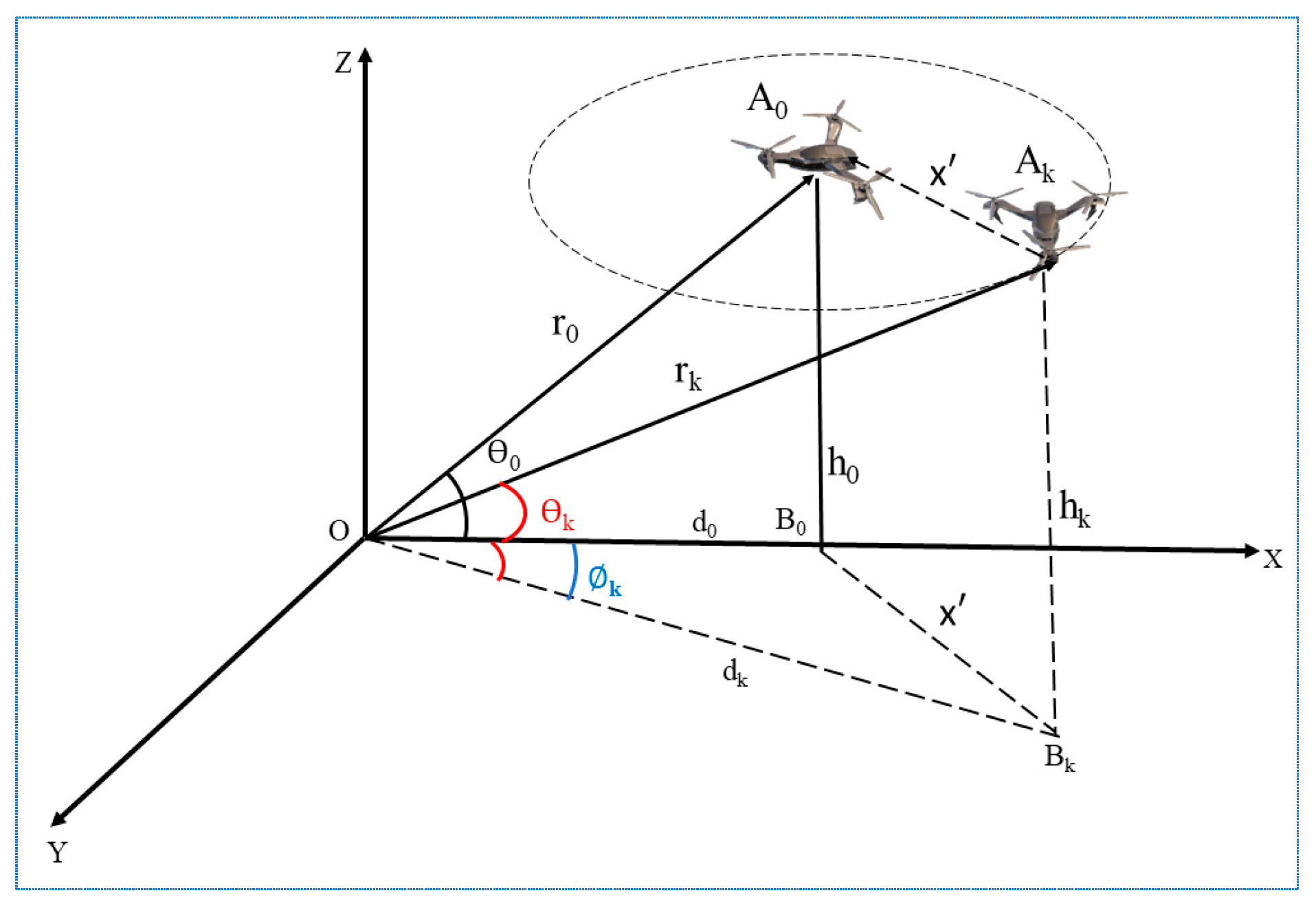
3.1. Problem Description and Assumptions

3.1.1. Problem Description

The multi-ray channel concept for G2A and A2A communications consists of several critical components that collectively create a comprehensive framework for developing and assessing UAV communication channels. The model includes both A2A and G2A communication pathways. Each UAV is equipped with a communication module enabling signal transmission and reception. Ground stations (GSs), strategically positioned across the operating area, act as communication hubs for G2A interactions. The location, speed, and altitude of each UAV are regularly adjusted to mimic real-life flight behaviors. UAVs are represented as mobile nodes in a multi-dimensional space capable of executing complex maneuvers. In contrast, GSs are static nodes with established positions equipped with antennas optimized for improving signal transmission and reception with UAVs.
The multi-ray propagation model improves the traditional LoS assumptions by incorporating multiple reflected and refracted rays. This model represents the complex dynamics of signals’ propagation in different scenarios, such as (1) the direct path LoS is considered as a primary signal path between the transmitter and receiver, (2) the secondary paths result from reflections of buildings, topography, and other obstructions. The reflected path is determined by its reflection coefficient, angle of incidence, path length, and (3) additional pathways created through diffraction around barriers and scatterers from more minor things or irregular surfaces. In addition, the framework includes actual descriptions of urban, suburban, and rural environments to ensure that it is suitable for various operating scenarios.
Consider a G2A communication scenario with multiple UAVs flying around the intended or targeted UAV, as illustrated in Figure 1. UAVs are assumed to fly independently at different altitudes. Let A be a set of UAVs, where A k indicates the scattered UAVs, each identified by unique indices k = 1,2 , 3 , , n . The intended UAV is denoted as A 0 and is assumed to be connected to the GS. To avoid collisions among flying vehicles, an appropriate distance of 10 m is maintained. Therefore, every flying vehicle is 10 m away from every other UAV. The shortest three-dimensional distance between the GS and the intended UAV is denoted by Equation (1).
r = x x 0 2 + y y 0 2 + z z 0 2
where x 0 , y 0 , and z 0 are the 3D Cartesian coordinates of the intended flying vehicle are on the x-axis, y-axis, and z-axis, respectively. The GS emits an omnidirectional radio wave signal towards the intended UAV located in a 3D environmental space. The emitted signal is transmitted to the targeted UAV directly via LoS. In the current environment, there may be several flying vehicles around the targeted UAV, interrupting the direct radio waves. As a result, the targeted UAV may receive several reflected, diffracted, or scattered propagating signals known as NLoS from surrounding UAVs across several propagation channels. These signals with different propagation lengths may be delivered to the targeted UAV with different time delays. The propagation durations may be equal for a few scattered drones located at similar distances from the targeted UAV, enabling signals to arrive at the receiver end at the same time. Therefore, the existence of an appropriate distance leads to improving the uniqueness of propagation paths among UAVs, avoiding duplication of the paths. Reflections from neighboring UAVs might create a multipath fading scenario between GS and the targeted UAV and may produce constructive or destructive interference that may interrupt communication. The alterations delay of arriving signals aids in the formation of a rich scattered environment that allows MIMO processing and results in increased data rates.

3.1.2. Assumptions

A variety of general assumptions are established to ensure that the multi-ray channel model for G2A and A2A communications is concise and accessible. These assumptions simplify the model’s complexities and allow a focus on important factors that influence the transmission of signals.
A-I: UAVs travel through regular and specified paths that can be regularly modified but remain known to the system at all times. The exact location of each UAV is determined by the Cartesian coordinates ( x k , y k , z k ) and can be transformed into polar coordinates. This aids in accurately modeling the transfer of signals.
A-II: The operating environment, such as urban, suburban, and rural, is considered to have comparable characteristics. For instance, urban regions have uniform high-rise building densities, while rural areas are wide and have few limitations.
A-III: The atmospheric circumstances are regarded as constant and do not change significantly throughout the communication intervals. To avoid obstructing the model, real-time atmospheric parameters, such as humidity, temperature, and pressure in the air, are assumed to be fixed.
A-III: UAVs and GS are coordinated with regard to the timing and frequency. This assumption removes the effect of timing lapses and frequency mismatches on the transmission.
A-IV: The surfaces with reflections in the environment are regarded as perfect reflectors with specified reflecting factors. This streamlined the estimation of reflection paths by assuming consistent reflection behavior. The radiation from scattering UAVs has different properties that depend on their spatial location and orientation in 3D space. The spatial location is considered the most important factor in defining the incidence and reflection angles of multipath objects moving towards the targeted UAV.
A-V: The antennas on UAVs and GS are supposed to have homogeneous power trends, which streamlines the model by omitting variations in antenna performance with directions. The transmission antenna of every UAV is omnidirectional, which can transmit signals isotopically in all directions.
A-VI: In the beginning, the straight path is determined using ideal LoS conditions. The reflections, diffractions, and scatterings are subsequently added to the basic conditions. To keep the model simple, a single bounced multipath component of transmitted radio waves is considered. This implies that the signals obtained by the targeted drone from GS are determined without listening to the reflections caused by nearby UAVs.

3.2. Description of the Multi-Ray Channel Model

The multi-ray channel model illustrates the propagation process of radio waves when the signal takes multiple pathways or routes while traveling from source to destination. The pathways consist of LoS, reflected, and diffracted paths. The received signal is formed of a few multipath elements, each of which has variable delays and amplitudes. Figure 1 illustrates the G2A communication process, and Figure 2 demonstrates its mapping to three-dimensional coordinates. The intended UAV A 0 needs a reliable communication mechanism to propagate with the GS at the origin O 0,0 , 0 . The attributes of the wireless communication channel, i.e., LoS path and received power, are found by multiple factors, including the propagation paths between the UAV and the GS.

3.2.1. Aerial Distance Between Intended UAV→GS

The intended UAV A 0 is shown in Figure 2, where Δ A 0 O B 0 forms a triangle. The h 0 represents the height of A 0 , and ϴ 0 represents its elevation angle. The shortest aerial distance between the intended UAV and GS is calculated by Equation (2).
r 0 = h 0 s i n ϴ 0
where r 0 is termed as the LoS component of the transmitted signal from GS and received at A 0 . Along with the LoS component, A 0 receives several other multipath components. These components are generated by the surrounding UAVs, known as scatterers, which fly in the nearby area.
The scatterers, each represented by A k , are located at different positions in the air and may reflect the radio waves towards the intended UAV. This results in creating a multipath scenario between the GS and the intended UAV. The A k position is identified by considering the triangle Δ A k O B k (See Figure 2), where h k represents the height and ϴ k shows the elevation angle of A k . The shortest aerial distance between A k and GS is indicated by r k . This is determined by Equation (3).
r k = h k s i n ϴ k

3.2.2. Distance Variations: Scatterer vs. Intended UAVs

The path length or distance between the intended A 0 and scatterers plays a vital role in defining the time delay of the received signal. A closely located A k may have a smaller time delay as compared to the one that is located far away. The distance between the intended A 0 and any A k is calculated by using the law of cosines. The relationship between GS and A 0 is determined by the LoS and the diffused component scattered by A k . The association of the propagation path lengths of these components is determined by the law of cosines as in Equation (4).
x k 2 = r 0 2 + r k 2 2 r 0 r k   c o s ϕ k
where x k represents the separation or variations between scattering A k and intended A 0 UAVs, and ϕ k indicates the azimuth angle among their projections. Equation (4) is further simplified by Equation (5).
x k 2 = r 0 r k 2 + 2 r 0 r k 1 c o s ϕ k
By substituting the values of r 0 and r k from Equations (2) and (3), and the trigonometric value ( 1 c o s ϕ k ) with 2 s i n 2 ϕ k 2 in Equation (5), we obtain the following Equation (6).
x k 2 = ( h 0 s i n ϴ 0   h k s i n ϴ k ) 2 + 4 h 0 s i n ϴ 0   h k s i n ϴ k s i n 2 ϕ k 2
Reorganizing Equation (6) and further simplifying it, we solve for x k we obtain Equation (7).
x k = ( h 0 s i n ϴ k h k s i n ϴ 0 ) ) 2 ( s i n ϴ 0 s i n ϴ k ) 2 + 4 h   0 h k s i n ϴ 0 s i n ϴ k s i n 2 ϕ k 2
By rearranging and further simplifying Equation (7), the obtained x k is shown by Equation (8).
x k = 1 s i n ϴ 0 s i n ϴ 1 ( h 0 s i n ϴ k h k s i n ϴ 0 ) ) 2 + 4 h 0 h k s i n ϴ 0 s i n ϴ k s i n 2 ϕ k 2
Equation (8) gives the separation or variations between the intended A 0 and the scattering A k UAVs.

3.2.3. Radio Wave Transmission

Let x k is the distance travelled by a radio wave from the GS to the intended UAV A 0 via the scattered UAV A k . This distance length is known as the NLoS component. The NLoS radio transmission occurs irrespective of the conventional LoS between the sender and the receiver, i.e., in the ground reflections. The x k can be determined by r k + x k . By substituting the values of r k from Equation (3) and x k from Equation (8), the obtained x k is shown by Equation (9).
x k = h k s i n ϴ k + 1 s i n ϴ 0 s i n ϴ k ( h 0 s i n ϴ k h k s i n ϴ 0 ) ) 2 + 4 h 0 h k s i n ϴ 0 s i n ϴ k s i n 2 ϕ k 2
By rearranging Equation (9), the propagation path of the reflected signal is defined by Equation (10).
x k = 1 s i n ϴ 0 s i n ϴ k h k s i n ϴ 0 + ( h 0 s i n ϴ k h k s i n ϴ 0 ) ) 2 + 4 h 0 h k s i n ϴ 0 s i n ϴ k s i n 2 ϕ k 2
When multiple UAVs function as scatterers A k , numerous reflected signals might reach the intended UAV A 0 , leading to a multipath environment. Such multipath signals approach the device receiving them with distinct time delays. Note that each A k has a distinct path length.

3.2.4. Time Delay Calculation

The amount of time delay T k associated with a propagated signal is determined by Equation (11).
T k =   x c
where x is the distance between GS and A 0 and c is the speed of light in a vacuum, approximately 3 × 10⁸ m per second. Signals with shorter path lengths have smaller time delays and reach earlier; however, the signal copies generated by A k (located far away) follow longer routes and are delivered with time delays.

3.2.5. Path Difference Calculation

The path loss is a reduction in the power density of a radio wave when it travels through scatterer UAVs. Various factors affect it, such as distance, frequency, and environmental situations. The difference in path lengths or arrival times is termed the path difference Δ x k and to determine its value, the LoS signal component is subtracted from the scattered reflected signal as shown by Equation (12).
Δ x k = x r 0
By substituting the values of x and r 0 in Equation (12) and further simplifying it, Equation (13) is written as.
Δ x k = h k s i n ϴ 0 h 0 s i n ϴ k s i n ϴ 0 s i n ϴ k + ( h 0 s i n ϴ k h k s i n ϴ 0 ) ) 2 s i n 2 ϴ 0 s i n 2 ϴ k + 4 h 0 h k s i n 2 ϕ k 2 s i n ϴ 0 s i n ϴ k
The value of the azimuth angle ϕ k operated in Equation (13) is determined by ϕ k = ϕ 0 ϕ k . When the value of ϕ 0 (the azimuth angle of the A 0 ) is assumed to be zero, the ϕ k = ϕ 0 ϕ k can be written as ϕ k = ϕ k . To further simplify the term h k s i n ϴ 0 h 0 s i n ϴ k of Equation (13), the values of s i n ϴ 0 and s i n ϴ k are substituted from Equations (2) and (3) to obtain h k h 0 r 0 h 0 h k r k and streamlined by Equation (14).
h k s i n ϴ 0 h 0 s i n ϴ k = h 0 h k r k r 0 r 0 r k
By replacing h 0 r 0 and h k r k by s i n ϴ 0 and s i n ϴ k , according to Equations (2) and (3), Equation (14) is modified as Equation (15).
h k s i n ϴ 0 h 0 s i n ϴ k   =   s i n ϴ 0 s i n ϴ k r k r 0 h k s i n ϴ 0 h 0 s i n ϴ k s i n ϴ 0 s i n ϴ k = r k r 0
By substituting the values from Equation (15) into Equation (13), the following Equation (16) is formed, after a few simplifying steps, to calculate the path difference.
Δ x k = r k r 0 + r 0 r k 2 + 4 r 0 r k s i n 2 ϕ k 2
Δ x k = r k r 0 + r 0 2 + r k 2 2 r 0 r k + 4 r 0 r k s i n 2 ϕ k 2
Δ x k = r k r 0 + r k 2 + r 0 2 2 r k r 0 + 4 r k r 0 s i n 2 ϕ k 2
Δ x k = r k r 0 + r k r 0 2 + 4 r k r 0 s i n 2 ϕ k 2
By simplifying Equation (16) further, Equation (17) is written as
Δ x k = r k r 0 + r k r 0 2 1 + 4 r k r 0 s i n 2 ϕ k 2 r k r 0 2    
By applying the Taylor series 1 + x = 1 + x x 2 2 + x 3 2 2 1 + to Equation (17) and taking the first two terms, we acquired Equation (18).
Δ x k = 2 r k r 0 + 2 r k r 0 r k r 0 2 s i n 2 ϕ k 2 2 r k r 0 8 r k r 0 3 s i n 4 ϕ k 2 +
Since the higher terms involve s i n 4 ϕ k 2 , s i n 6 ϕ k 2 , and so on, the higher terms can be truncated after the 2nd term, if
4 ( r k r 0 ) 2 8 r k r 0 3 s i n 4 ϕ k 2 2 r k r 0 r k r 0 2   s i n 2 ϕ k 2
This implies
r k r 0 r k r 0 2 s i n 2 ϕ k 2 1
s i n 2 ϕ k 2 r k r 0 2 r k r 0
This condition implies that, if x k and r 0 are close, i.e., r k r 0 , then ( r k r 0 ) 2 is small, and the approximation is only valid for very small values of ϕ k . However, if r k   a n d   r o are far apart, then ( r k r 0 ) 2   r k   r o , then, the higher-order terms become negligible.
Hence, by ignoring higher-order terms, the expression becomes,
Δ x k = 2 r k r 0 + 2 r k r 0 r k r o   s i n 2 ϕ k 2
Δ x k =   2 r k r 0 + r k r 0 ( r k r 0 ) 1 c o s ϕ k 2
The phase difference for reflected rays is given by Equation (19).
Δ ϕ   =   2 π Δ x k λ
By substituting the value of Δ x k in Equation (19) and the modified equation is in Equation (20).
Δ ϕ k = 4 π r k r 0 + r k r 0 ( r k r 0 ) 1 c o s ϕ k 2 λ

3.2.6. Power Equation for Multipath Reflected Rays

Multipath propagation creates challenges, including fading, because the strength of signals changes in response to positive and negative interference over various paths. The power equation is rationalized for multiple reflected rays having different time delays. The procedure takes into consideration the distinct characteristics of every reflected ray, including its time delay, amplitude, and phasing shift. By integrating all these factors into a single power equation, we can clarify the rays’ actions and anticipate the resulting signal. The enhanced equation facilitates the computing process while also enhancing simulation accuracy in challenging reflected scenarios. The power equation is shown in Equation (21).
P r = P t G r λ 4 π d 2   × G r 0 r 0 + Γ ϴ k , ϕ k + G x 1 e j 2 π x 1 r 0 λ x 1   + Γ ϴ k , ϕ k + G x 2 e j 2 π x 2 r 0 λ x 2 +     + Γ ϴ k , ϕ k + G x n e j 2 π ( x n r 0 ) λ x n   2
Equation (21) is further simplified by taking into account the following considerations: r 0 = x 1 = x 2   = x 3 = x k = d and G r 0 = G x 1 = G x 2 = G x 3   = G x k   = G t , to obtain Equation (22).
P r = P t G t G r λ 4 π d 2   × 1 + Γ ϴ k , ϕ k [ e j Δ ϕ x 1 + e j Δ ϕ x 2 + e j Δ ϕ x 3 + e j Δ ϕ x k 2
By applying the Taylor series e x = n = 0 x n n ! = 1 + x + x 2 2 + x 3 6 + to Equation (22) and by taking the first two components, we obtain Equation (23).
P r = P t G t G r λ 4 π d 2 × 1 + Γ ϴ k , ϕ k   1 j ( Δ ϕ x 1 ) + 1 j Δ ϕ x 2 + 1 j ( Δ ϕ x 3 ) + 1 j ( Δ ϕ x k ) 2
P r = P t G t G r λ 4 π d 2 × 1 + Γ ϴ k , ϕ k k = 1 k = K ( k j ( Δ ϕ k ) ) 2
Furthermore, the formula may be written with homogeneous reflection, such as the coefficient of reflection ( Γ ) = 1. This situation indicates that each of the reflections is particularly homogeneous, meaning that every reflected ray maintains its initially generated amplitude without losses. By establishing these assumptions, the formula becomes less complex and enables apparent analysis. This equation is particularly useful and anticipates ideal reflecting situations, including modelling highly reflected surfaces and examining ideal mirror structures in optical and acoustic situations. The equation is anticipated by Equation (24).
P r = P t G t G r λ 4 π d 2 × 1 + k = 1 k = K ( k j ( Δ ϕ k ) ) 2
For analyzing the scenario of two rays, we determine k = 1 and the coefficient of reflection ( Γ ) = −1 in the formula in Equation (24). By adding specific numbers, the formula is simplified to explain the interactions among both beams. This situation requires two-ray experiences after reflection, indicated by ( Γ ) = −1. Overall, the updated equation leads to an improved understanding of the actions and interactions of both rays, which makes it easy to foresee and evaluate the combined impact. The resultant formula is anticipated by Equation (25).
P r = P t G t G r λ 4 π d 2 × ( Δ ϕ k ) 2
By substituting the Δ ϕ k from Equation (20) in Equation (25), the updated formula is obtained by Equation (26).
P r = P t G t G r λ 4 π d 2 ×   4 π r k r 0 1 + r k r 0 s i n 2 ϕ k 2 λ 2
By simplifying Equation (26) further, we obtain Equation (27) as follows.
P r = P t G t G r × r k r 0 1 + r k r 0 s i n 2 ϕ k 2 d 2
The r k and r 0 represent the path lengths associated with the scatterer and intended UAVs, respectively. The ϕ k value corresponds to the azimuth angle between these UAVs. Particularly, r k indicates the amount of distance covered by transmitted signals dispersed from non-primary targets, whereas r 0 refers to the distance travelled by signals from the targeted UAV. The azimuth angle ( ϕ k ) defines the directional relationship among scattered and targeted UAVs, affecting the transfer of signals. Identifying these factors is essential for modelling and anticipating the behavior of the signal in situations involving multiple UAVs.

4. Model Development, Experiments, and Results

A quasi-realistic propagation scenario is developed in MATLAB® R2020b to evaluate and validate the proposed multi-ray channel model’s capabilities. By mimicking scenarios from the real world, the model’s efficiency and capability are thoroughly tested and properly assessed. In this study, the radar cross section (RCS), commonly referred to as radar signatures, is considered, which specifies the reflecting characteristics of scattering UAVs. The RCS is created utilizing a facet-based drone model, specifically the Parrot Anafi, using the MATLAB® application EPOFACET [79]. Figure 3 illustrates an example of a multifaceted drone model.
The simulation has similarities to G2A propagating scenarios, which consider the scattering of UAVs. These UAVs are commonly composed of reflecting components that may allow signals to transmit from GS to reflect off their outsides, leading to a multipath scenario surrounding the intended UAV. To prevent collisions involving UAVs, an appropriate separation distance is maintained, which is determined by the size and specific requirements of the flying vehicles. Therefore, establishing a quasi-realistic model for both G2A and A2A propagation scenarios allows an in-depth investigation of the channel’s behavior’s influence because of the heights and distances between the intended and the surrounding UAVs (or scatterers). The proposed modelling approach facilitates recognizing the unpredictable behavior of communication routes under varying operating circumstances, thus enhancing the durability and reliability of UAV propagation systems.
The proposed multi-ray channel model is evaluated using the parameter values listed in Table 3. This framework is based on the ray-tracing concept, illustrating an environment populated by randomly arranged scattering UAVs. In our case study, we analyzed a targeted UAV operating among 200 dispersing UAVs. In order to assess the validity of the proposed model, the simulation outcomes have been compared with the measurement data obtained by Jeong et al. described in [80] and in another model described in [81]. The findings indicate that the proposed model aligns with both the measured outcomes and other tested models.
Figure 4 compares the multi-ray model results and the measured data using parameters K = 200 and d = 3 m. The findings reveal that the multi-ray model fits the measured data remarkably well, indicating its effectiveness in accurately modelling propagation behavior. This highlights the model’s ability to handle multipath effects and wave interactions, essential in intricate propagation settings. Figure 5 shows the results of the proposed model against established models, including ray tracing, the analytical two-ray model, measured data, and free-space outcomes. The comparison illustrates that the proposed model matches the measured data and effectively captures vital propagation characteristics such as reflections, diffraction, and wave interference. This further emphasizes the model’s strength and relevance for real-world wireless communication applications, showcasing its importance in advanced propagation modelling techniques.

4.1. Impact Analysis of Various Factors on Received Power

In wireless communication systems, the characteristics of radio signals, including received power and path loss, depend on channel propagation. Received power is considered an important parameter for evaluating the performance of the communication link in terms of reliability and efficiency. The multipath signals are assumed to be summed in accordance with their delays in obtaining the received power. The characteristics of multipath signals might alter depending on continuously changing the transmitter, scatterers, or receiver positions. This study considers various factors to determine the impact on the received power. These factors include the receiver’s altitude, the number of drones in the receiver’s neighborhood, the distance between scattering UAVs, transmitters, and propagation. The impact of each factor on the received power is explained in more detail below.

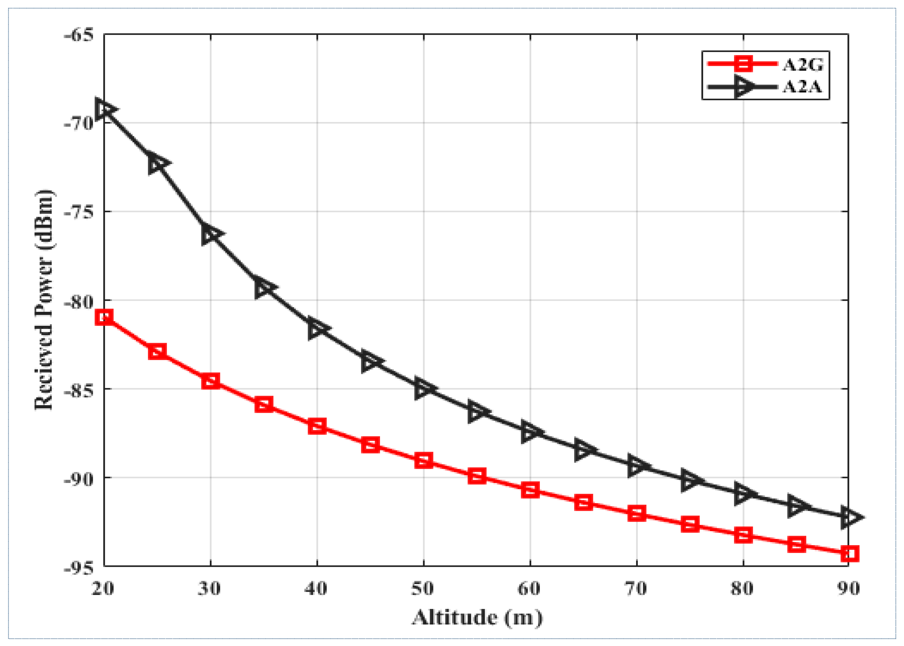
4.1.1. Altitude of the Receiver

The key objective of UAVs is to perform tasks by flying without any hindrance, and it is important to evaluate the operation of the network thoroughly. UAV operations cannot be assumed to follow a particular pattern since they must randomly finish their tasks by following any best path. The path may consist of any shape and have various heights and distances. The UAVs follow the selected routes based on environmental requirements. Unlike traditional ground-based communication systems, UAVs can fly at specific heights, allowing them to overcome obstructions such as trees and buildings that typically hinder signal transmission. This ability enables UAVs to achieve better signal propagation conditions and improve their power reception estimates. To gain insight into the performance of UAVs while allocated into the airspace to fly. Figure 6 represents a comparative analysis of the received power against altitude in G2A and A2A communication link scenarios. In the A2A communication scenario, the transmitting flying vehicle travelling in the airspace has a higher received signal strength than in the G2A communication scenario.
Figure 6 demonstrates an analysis of power received against height in G2A and A2A communication circumstances. In the A2A communication scenario, the transmitter UAV performs at elevated heights, leading to a significantly greater strength of the received signal than in the G2A scenario. This is the case since, in the A2A situation, the signal experiences fewer obstacles and degradation as it travels through less dense atmospheric layers, clear from the interference common in G2A transmission, including buildings and trees. The study illustrates the advantages of A2A communications in maintaining robust signal quality at different elevations.

4.1.2. Horizontal Flight of the Receiver

UAVs are usually employed to perform tasks remotely across extended distances. Such UAVs must travel far from their base station to execute activities, including deliveries or rescue operations. To guarantee timely activities, UAVs initially reach a specified height before moving towards their targeted locations horizontally. This horizontal flight may cover far distances to accomplish the set goals. When the distance between the UAVs and the base station increases, the UAVs conform to additional potential obstacles, such as reflections from the base and nearby foundations. Such variables may raise the number of multipath signals the UAV obtains, allowing multiple signal copies to reach it with different delays. This may generate positive or negative disruptions, decreasing the signal power received. To examine the channel features of UAVs during horizontal flight, it is necessary to employ a model that considers changing distances. This is important because the goal of the UAV system is to reach across restricted places, thus enhancing the network’s overall coverage. Therefore, assessing the network’s efficiency when UAVs are dispersed over wide areas is essential.
Figure 7 provides a relationship between the received power and the horizontal distance for both scenarios, such as G2A and A2A communication scenarios. In A2A communication, the central or base station and other drones comprising intended and dispersed UAVs are dispersed in the airspace. Therefore, A2A communication offers stronger received radio signals than G2A. This improved signal strength in A2A communication is caused by fewer obstacles and barriers, including buildings and geography, that usually disrupt G2A transmission. A straight LoS and few obstacles in the airspace enhance the transmission of signals while decreasing attenuation, leading to higher transmitted power levels throughout comparable horizontal distances. This investigation demonstrates the benefits of A2A communication in terms of sustaining a strong and constant signal strength over long horizontal distances.

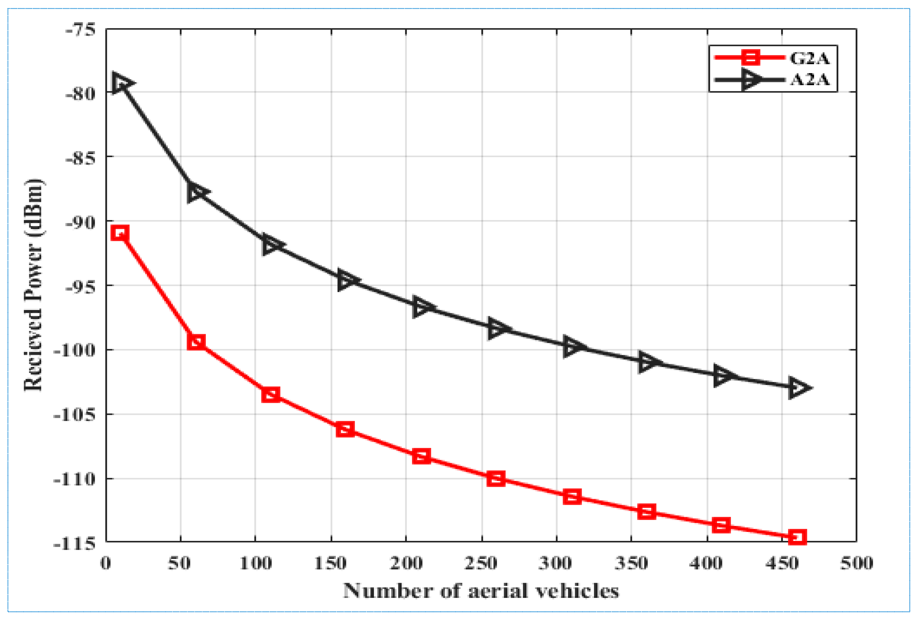
4.1.3. Increase in Number of Flying Vehicles

While carrying out tasks utilizing a UAV network, a certain number of UAVs are allocated to perform the activity. The goal could involve various tasks; the number of UAVs required to complete these tasks may be improved based on their characteristics and complexity. The number of UAVs could differ for simultaneous activities in the same geographic area. Altering the number of UAVs across an established coverage area impacts the reflected and multipath signals of transmitted radio signals. Raising the number of UAVs lowers the path lengths and time delays of signal copies, leading to higher deviations in received power, and vice versa, for studying the consequence of varying numbers of UAVs on channel characteristics. As demonstrated in Figure 8, the amount of power received collapses as the number of UAVs increases. The simulations, which occurred at the frequency of 2.4 GHz, comprised various UAVs, such as 5, 100, 150, 200, and 455. An appropriate distance of 3 m has been established between the UAVs to prevent potential clashes.
Figure 8 illustrates an analysis of received power against varying numbers of UAVs in both G2A and A2A communication scenarios. In an A2A communication, the sender UAV operates at higher elevations, leading to higher received signal strength than G2A. The variation occurs due to lower interference signals and obstacles limiting G2A communication. In the A2A scenario, a straight LoS and limited obstructions in the airspace enable improved signal transmission and lower attenuation. This results in increased received power levels even though the number of UAVs increases. Conversely, within the G2A situation, obstacles and multipath impacts resulting from surface reflections could result in transmission degradation, especially when the number of UAVs increases. The information in Figure 8 demonstrates how raising the amount of UAVs influences received power in both instances. The findings indicate that the power downfalls numerous UAVs receive are due to more complex multipath interactions. This A2A communication scenario constantly exceeds the G2A situation. This illustrates the advantages of A2A communication in maintaining robust signal strength regardless of the different densities of UAV operations.

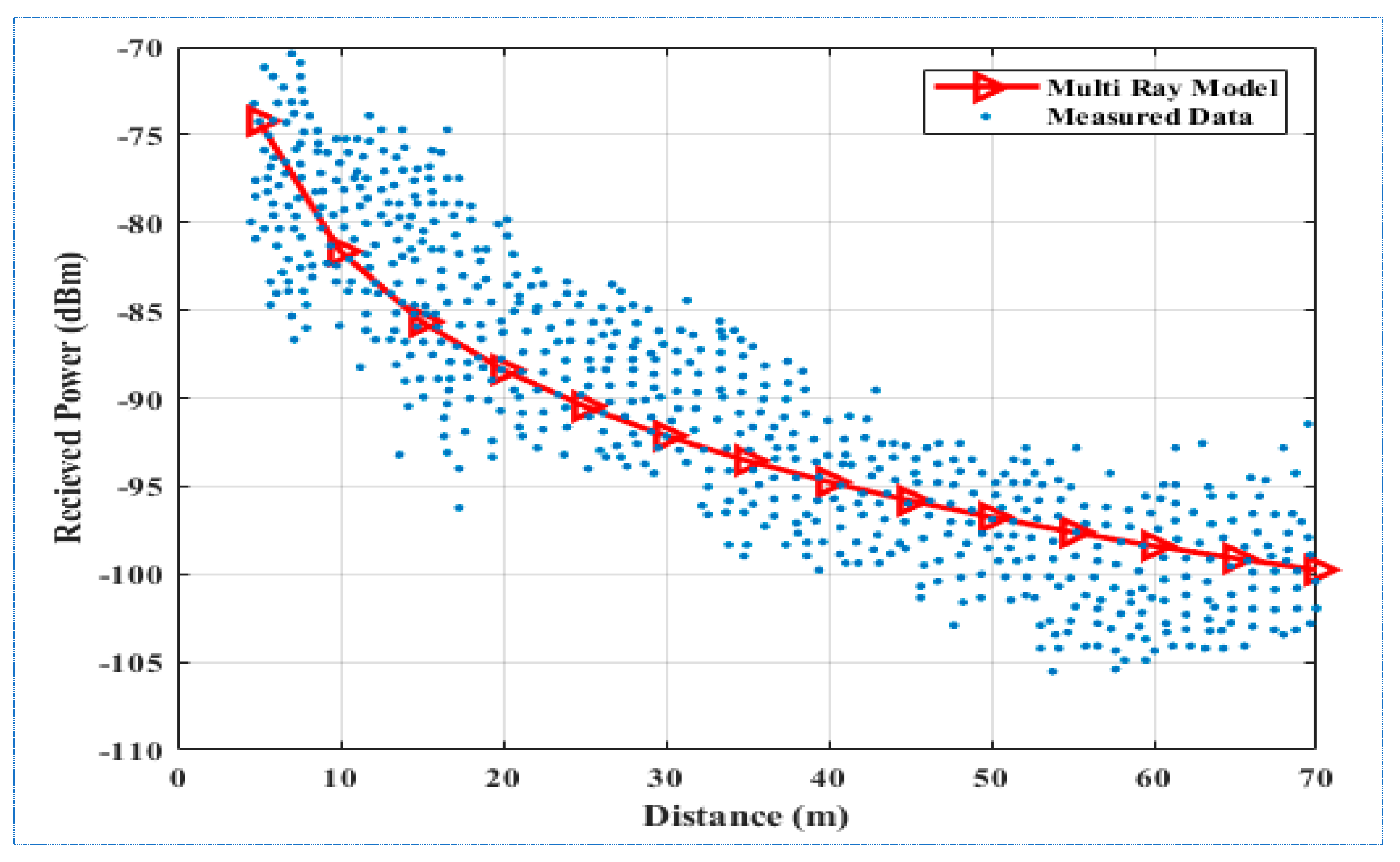
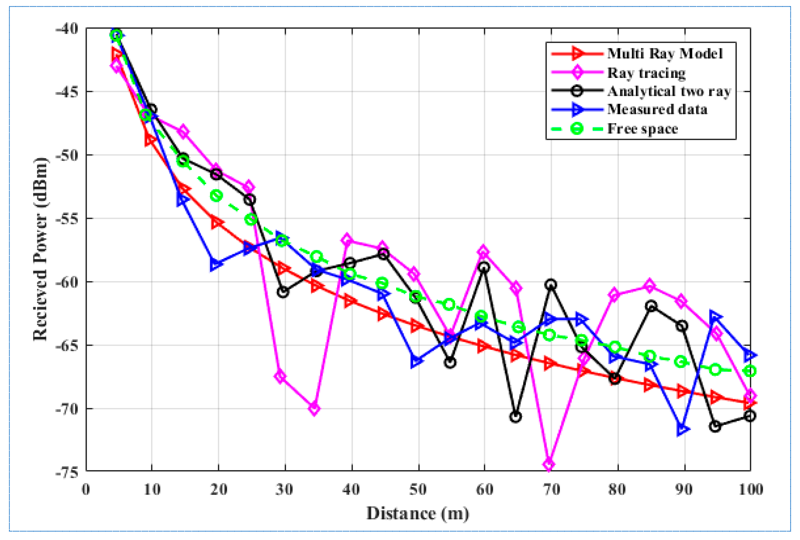
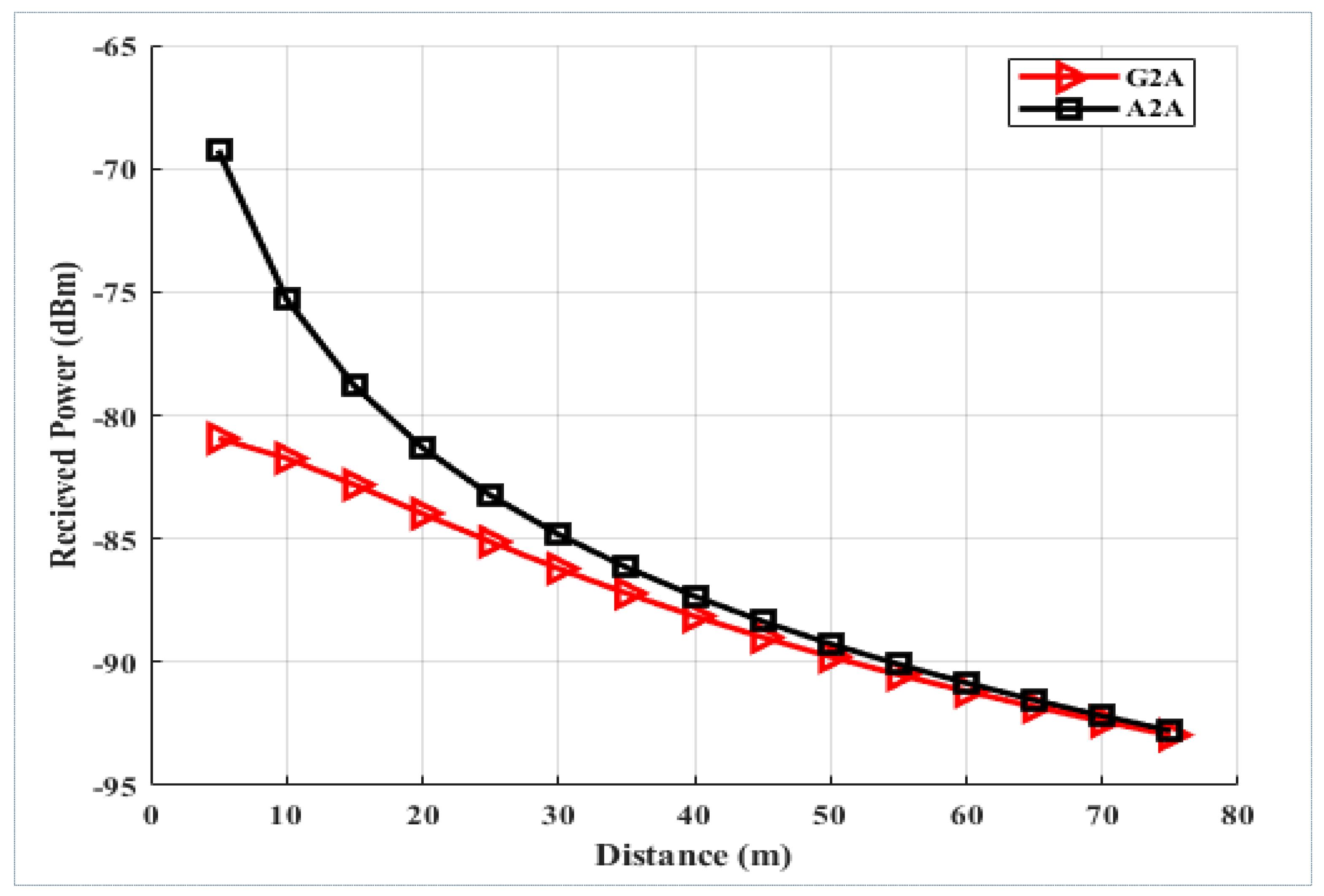
4.1.4. Increase in Propagation Distance

Based on their operational requirements, UAVs may travel on many direct routes (left, right, upward, or horizontally). Usually, these UAVs move in both vertical and horizontal directions to get to their targets effectively. The simultaneous movement is referred to as the propagation distance. In such scenarios, when the UAV rapidly alters positions in every direction, an unexpected phase change is anticipated because of the incident’s angle alterations. The phase shifting results in variations in the estimated RCS, which impact the received power at the intended UAV. To comprehend channel behavior while the UAVs move in vertical and horizontal directions. The outcomes clearly demonstrate how signal power strength decreases with increased propagation distances.
Figure 9 illustrates the received power vs propagation distance analysis for G2A and A2A communication links. The investigation demonstrates that the strength of the received signal is significantly higher in A2A communication than in G2A. This difference arises from the A2A scenario, where the transmitter UAV is placed in the airspace with other UAVs, providing an improved LoS while decreasing obstacles. By contrast, the G2A situation includes communication between a base station and a UAV, which is more likely to come across physical barriers and environmental conditions that may decrease signal strength. Therefore, the greater altitude of both the sender and receiver UAVs in the A2A situation contributes to more effective and robust transmissions of signals.

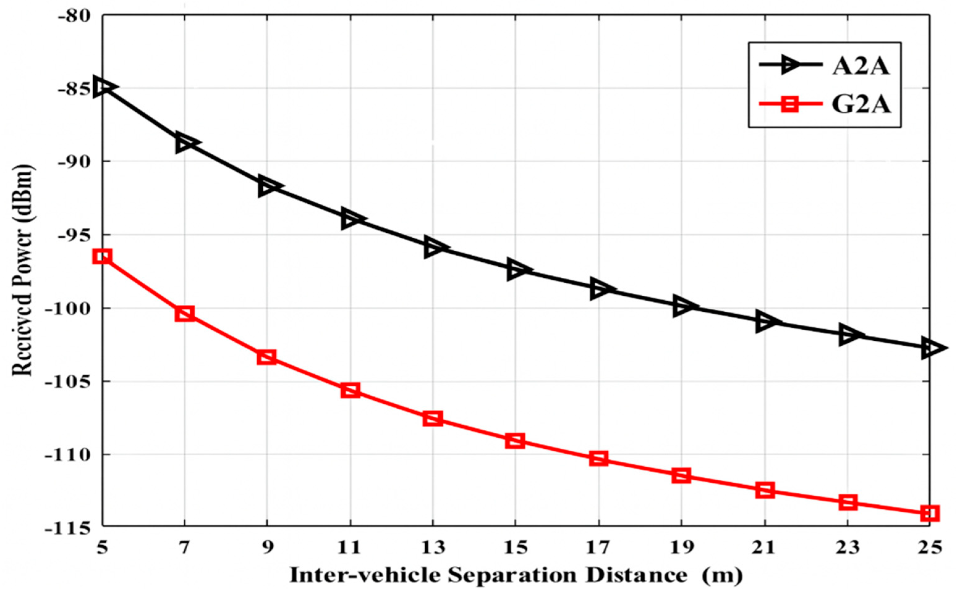
4.1.5. Increase in Inter-Vehicle Separation Distance

UAVs move across all directions to accomplish goals in several activities, including rescue operations or military conflicts. Therefore, the area spanned by these UAVs differs by growing or reducing the distances. The dynamic mobility impacts the channel lengths of multipath signals, producing variations in the time delays. A UAV’s time delay increases when it travels away from the targeted UAV, but decreases when it gets closer. This situation depicts a scenario in which several actions are performed in the surroundings, leading to a change in the UAV network’s coverage area and, consequently, the coverage radius expanding or diminishing. The variations in the network’s radius generate differences in signal reflections and multipath impacts, ultimately influencing the received signal. In G2A, communication systems with longer spacing distances between UAVs deal with additional obstacles and surface reflections than systems with smaller separation distances. The multipath environments are studied through simulations that need to be performed to study channel characteristics when drones travel at different distances from the targeted UAV. The experiments demonstrated that the signal strength received at a targeted UAV is more powerful when a separation distance is 5 m than a separation distance of 25 m. The larger radius supports additional UAVs, leading to a decrease in transmitted signal strength, which results in higher route loss and multipath impacts.
Figure 10 depicts an analysis of received power and inter-UAV separation distances in G2A and A2A communication links. The outcomes demonstrate that the received power is substantially greater in the A2A situation (black curve) than in the G2A situation (red curve). The variation in received power results from the base station’s existence in the airspace during A2A communication. In the A2A situation, the base station’s altitude position minimizes barriers and increases the LoS communication between UAVs, leading to improved transmission of signals. This outstanding place reduces signal loss and multipath impacts, particularly prominent in G2A communications. Since the base station occupies the ground, the signals must cope with extra obstacles and reflections caused by the environment. In addition, the shorter distance between UAVs in the A2A scenario compared to the G2A situation leads to a rise in received power. The UAVs’ proximity leads to a more powerful and direct communication relationship, reducing path loss and raising signal strength. In conclusion, the information displayed in Figure 10 indicates the greater efficiency of A2A communication about received power due to the favorable placement of the base station in the airspace and shorter inter-UAV separation distances. This contrast illustrates the advantages of utilizing A2A communication systems in UAV networks to enhance efficiency and dependability.
This research advances the field of UAV communication by developing and validating a multipath channel model for both G2A and A2A communications. The study effectively tackles the challenges of multipath propagation in aerial networks, demonstrating how reflections from nearby UAVs can disrupt the intended signal, thus reducing communication efficiency. A key strength of this research lies in its combination of simulation-based analysis and empirical validation, ensuring that the proposed model is consistent with real-world findings. The study successfully simulates realistic communication scenarios by considering the geographical distribution of UAVs and assessing variations in received power. Furthermore, the model offers a framework for optimizing UAV communication systems, providing crucial insights for future research and network planning.
In addition to strengths, this research also identifies specific limitations that require further investigation. While the study addresses multipath effects, it overlooks real-world environmental factors such as weather, terrain changes, and moving obstacles that can significantly affect signal propagation. The dependence on static or predetermined UAV placements may restrict the model’s relevance in dynamic aerial networks where UAVs frequently change positions. Furthermore, the study primarily examines signal attenuation from multipath reflections but neglects to explore strategies for managing interference or techniques for mitigation. For future enhancements, integrating a broader range of variables, including multiple base stations, varying transmission power, and real-time network feedback, would greatly improve the model’s realism and flexibility.

5. Conclusions and Future Works

This paper has presented a multipath channel model tailored for G2A and A2A communications within UAV networks, emphasizing the influence of multipath propagation from surrounding UAVs. A simulation that combines theoretical calculations with geographic UAV placements has also been developed to assess received power under multipath conditions. The proposed multi-ray channel model was corroborated with empirical data and existing theoretical frameworks, showcasing its precision in evaluating communication efficiency within aerial networks. Findings reveal that reflections from nearby UAVs can compromise the intended signal, thereby diminishing communication efficiency. The results validate that multipath propagation negatively impacts signal quality, while the model adeptly measures these effects, serving as a useful resource for analyzing UAV communication performance. Although the research advances our understanding of UAV communication in multipath environments, further progress is needed to develop a more adaptive and comprehensive approach. Future enhancements will expand the model’s usability by integrating environmental and operational elements, such as extensive UAV networks, numerous base stations, and diverse transmission power. To boost accuracy, it will consider realistic signal dispersion, multi-bounce reflections, and environmental factors like weather and terrain. Furthermore, adaptive algorithms for real-time communication adjustments and experimental validation in various contexts will further improve the model for effective UAV network implementation.

Author Contributions

Conceptualization: F.A. and M.Y.M.M.; Methodology: F.A. and M.Y.M.M.; Modeling: F.A. and M.Y.M.M.; Software: F.A.; Formal Analysis: I.H. and K.A.; Writing—Original Draft Preparation: F.A.; Writing—Review and Editing: F.A. and I.H.; Supervision: M.Y.M.M. All authors have read and agreed to the published version of the manuscript.

Funding

This research received no external funding.

Data Availability Statement

Data may be provided on demand.

Conflicts of Interest

The authors declare no conflicts of interest.

References

  1. Jung, S.; Kim, H. Analysis of amazon prime air UAV delivery service. J. Knowl. Inf. Technol. Syst. 2017, 12, 253–266. [Google Scholar]
  2. Ling, A.H.M.; Sia, J.K.-M.; Ho, J.M. Investigating consumers’ intention to use drone food delivery services: Do personality traits matter? Asia Pac. J. Mark. Logist. 2024, 36, 3025–3042. [Google Scholar] [CrossRef]
  3. De Schrijver, S. Commercial use of drones: Commercial drones facing legal turbulence: Towards a new legal framework in the EU. US-China Rev. 2019, 16, 338. [Google Scholar] [CrossRef]
  4. Shenoy, K.K. From innovation to integration of drones in business ecosystem: Commercial and civilian drone opportunities and regulatory challenges. Int. J. Intellect. Prop. Manag. 2024, 14, 309–324. [Google Scholar] [CrossRef]
  5. Tasouji, Y. Lifting Off: Commercial Drone Services and Regulations in Canada. Master’s Thesis, Simon Fraser University, Burnaby, BC, Canada, 2023. [Google Scholar]
  6. ITU-R M.2160; Framework and Overall Objectives of the Future Development of IMT for 2030 and Beyond. International Telecommunication Union–Radiocommunication Sector (ITU-R): Geneva, Switzerland, 2023.
  7. Yan, C.; Fu, L.; Zhang, J.; Wang, J. A comprehensive survey on UAV communication channel modeling. IEEE Access. 2019, 7, 107769–107792. [Google Scholar] [CrossRef]
  8. Khuwaja, A.A.; Chen, Y.; Zhao, N.; Alouini, M.-S.; Dobbins, P. A survey of channel modeling for UAV communications. IEEE Commun. Surveys Tuts. 2018, 20, 2804–2821. [Google Scholar] [CrossRef]
  9. Zhang, Y.; Wen, J.; Yang, G.; He, Z.; Luo, X. Air-to-air path loss prediction based on Machine Learning methods in urban environments. Wirel. Commun. Mob. Comput. 2018, 2018, 8489326. [Google Scholar] [CrossRef]
  10. Colpaert, A.; Vinogradov, E.; Pollin, S. Aerial coverage analysis of cellular systems at LTE and mmWave frequencies using 3D city models. Sensors 2018, 18, 4311. [Google Scholar] [CrossRef]
  11. Greenberg, E.; Levy, P. Channel characteristics of UAV to ground links over multipath urban environments. In Proceedings of the 2017 IEEE International Conference on Microwaves, Antennas, Communications and Electronic Systems (COMCAS), Tel Aviv, Israel, 13–15 November 2017; pp. 1–4. [Google Scholar]
  12. Zhu, L.; He, D.; Guan, K.; Ai, B.; Zhong, Z.; Li, D. Channel characterization and simulation for unmanned aerial vehicle communication. In Proceedings of the IEEE International Symposium on Antennas and Propagation and USNCURSI Radio Science Meeting, Atlanta, GA, USA, 7–12 July 2019; pp. 2135–2136. [Google Scholar]
  13. Athanasiadou, G.E.; Tsoulos, G.V. Path loss characteristics for UAV-to-ground wireless channels. In Proceedings of the 2019 13th European Conference on Antennas and Propagation (EuCAP), Krakow, Poland, 5 April 2019; pp. 1–4. [Google Scholar]
  14. Chu, X.; Briso, C.; He, D.; Yin, X.; Dou, J. Channel modeling for low-altitude UAV in suburban environments based on ray tracer. In Proceedings of the 12th European Conference on Antennas and Propagation (EuCAP 2018), London, UK, 9–13 April 2018. [Google Scholar]
  15. Zhao, D.; Huang, C.; Wang, C.X.; Li, J. Scenario Classification and Channel Modeling for MIMO Communications in Suburban Road Scenarios. In Proceedings of the 2024 18th European Conference on Antennas and Propagation (EuCAP), Glasgow, UK, 17–22 March 2024; pp. 1–5. [Google Scholar]
  16. Cui, Z.; Guan, K.; He, D.; Ai, B.; Zhong, Z. Propagation modeling for UAV air-to-ground channel over the simple mountain terrain. In Proceedings of the 2019 IEEE International Conference on Communications Workshops (ICC Workshops), Shanghai, China, 20–24 May 2019; pp. 1–6. [Google Scholar]
  17. Jawhly, T.; Tiwari, R.C. Loss exponent modeling for the hilly forested region in the VHF band III. Radio Sci. 2021, 56, e2020RS007201. [Google Scholar] [CrossRef]
  18. Andersen, J.B.; Rappaport, T.S.; Yoshida, S. Propagation measurements and models for wireless communications channels. IEEE Commun. Mag. 1995, 33, 42–49. [Google Scholar] [CrossRef]
  19. Cui, Z.; Guan, K.; Briso, C.; He, D.; Ai, B.; Zhong, Z. Probabilistic two-ray model for air-to-air channel in built-up areas. arXiv 2019, arXiv:1906.10909. [Google Scholar]
  20. Ranchagoda, N.H.; Sithamparanathan, K.; Ding, M.; Al-Hourani, A.; Gomez, K. Elevation-angle based two-ray path loss model for air-to-ground wireless channels. Veh. Commun. 2021, 32, 100393. [Google Scholar] [CrossRef]
  21. Faruque, S. A three ray propagation model for PCS and micro-cellular services. In Proceedings of the MILCOM’95, San Diego, CA, USA, 5–8 November 1995; pp. 1239–1243. [Google Scholar]
  22. He, R.; Zhong, Z.; Ai, B.; Ding, J.; Guan, K. Analysis of the relation between Fresnel zone and path loss exponent based on two-ray model. IEEE Antennas Wirel. Propag. Lett. 2012, 11, 208–211. [Google Scholar]
  23. Matolak, D.W. Air-ground channels & models: Comprehensive review and considerations for unmanned aircraft systems. In Proceedings of the 2012 IEEE Aerospace Conference, Big Sky, MT, USA, 3–10 March 2012; pp. 1–17. [Google Scholar]
  24. Gürses, A.; Sichitiu, M.L. Air-to-Ground Channel Modeling for UAVs in Rural Areas. In Proceedings of the 2024 IEEE 100th Vehicular Technology Conference (VTC2024-Fall), Washington, DC, USA, 7–10 October 2024; pp. 1–6. [Google Scholar]
  25. Matolak, D.W.; Sun, R. Air-ground channel characterization for unmanned aircraft systems: The hilly suburban environment. In Proceedings of the 2014 IEEE 80th Vehicular Technology Conference (VTC2014-Fall), Vancouver, BC, Canada, 14–17 September 2014; pp. 1–5. [Google Scholar]
  26. Alzahrani, B.; Oubbati, O.S.; Barnawi, A.; Atiquzzaman, M.; Alghazzawi, D. UAV assistance paradigm: State-of-the-art in applications and challenges. J. Netw. Comput. Appl. 2020, 166, 102706. [Google Scholar] [CrossRef]
  27. Zöchmann, E.; Guan, K.; Rupp, M. Two-ray models in mmWave communications. In Proceedings of the 2017 IEEE 18th International Workshop on Signal Processing Advances in Wireless Communications (SPAWC), Sapporo, Japan, 3–6 July 2017; pp. 1–5. [Google Scholar]
  28. Dabiri, M.T.; Safi, H.; Parsaeefard, S.; Saad, W. Analytical channel models for millimeter wave UAV networks under hovering fluctuations. IEEE Trans. Wirel. Commun. 2020, 19, 2868–2883. [Google Scholar] [CrossRef]
  29. Djimantoro, M.I.; Suhardjanto, G. The advantage by using low-altitude UAV for sustainable urban development control. In Proceedings of the IOP Conference Series: Earth and Environmental Science, Qingdao, China, 26–29 June 2017; p. 012014. [Google Scholar]
  30. Parsons, J.D.; Parsons, P.J.D. The Mobile Radio Propagation Channel; Wiley: New York, NY, USA, 2000; Volume 2. [Google Scholar]
  31. Macharia, R.; Lang’at, K.; Kihato, P. Interference management upon collaborative beamforming in a wireless sensor network monitoring system featuring multiple unmanned aerial vehicles. In Proceedings of the 2021 IEEE AFRICON, Arusha, Tanzania, 13–15 September 2021; pp. 1–6. [Google Scholar]
  32. Mirza, M.-Y.; Khan, N. Correction to: G2a communication channel modeling and characterization using confocal prolates. Wirel. Pers. Commun. 2020, 115, 11. [Google Scholar] [CrossRef]
  33. Shakoor, S.; Kaleem, Z.; Baig, M.I.; Chughtai, O.; Duong, T.Q.; Nguyen, L.D. Role of UAVs in public safety communications: Energy efficiency perspective. IEEE Access 2019, 7, 140665–140679. [Google Scholar] [CrossRef]
  34. Hadi, H.J.; Cao, Y.; Nisa, K.U.; Jamil, A.M.; Ni, Q. A comprehensive survey on security, privacy issues and emerging defence technologies for UAVs. J. Netw. Comput. Appl. 2023, 213, 103607. [Google Scholar] [CrossRef]
  35. Al-Hourani, A.; Kandeepan, S.; Jamalipour, A. Modeling air-to-ground path loss for low altitude platforms in urban environments. In Proceedings of the 2014 IEEE Global Communications Conference, Austin, Texas, USA, 8–12 December 2014; pp. 2898–2904. [Google Scholar]
  36. Ahmad, A.; Cheema, A.A.; Finlay, D. A survey of radio propagation channel modelling for low altitude flying base stations. Comput. Netw. 2020, 171, 107122. [Google Scholar] [CrossRef]
  37. Kim, E.; Kim, J.; Kim, J.-H.; Lee, H. HiMAQ: Hierarchical multi-agent Q-learning-based throughput and fairness improvement for UAV-Aided IoT networks. J. Netw. Comput. Appl. 2024, 223, 103813. [Google Scholar] [CrossRef]
  38. Tuna, G.; Nefzi, B.; Conte, G. Unmanned aerial vehicle-aided communications system for disaster recovery. J. Netw. Comput. Appl. 2014, 41, 27–36. [Google Scholar] [CrossRef]
  39. Cui, Z.; Briso, C.; Guan, K.; Matolak, D.W.; Calvo-Ramírez, C.; Ai, B.; Zhong, Z. Low-altitude UAV air-ground propagation channel measurement and analysis in a suburban environment at 3.9 GHz. IET Microw. Antennas Propag. 2019, 13, 1503–1508. [Google Scholar] [CrossRef]
  40. Zhu, Q.; Jiang, S.; Wang, C.-X.; Hua, B.; Mao, K.; Chen, X.; Zhong, W. Effects of digital map on the RT-based channel model for UAV mmWave communications. In Proceedings of the 2020 International Wireless Communications and Mobile Computing (IWCMC), Limassol, Cyprus, 15–19 June 2020; pp. 1648–1653. [Google Scholar]
  41. Zhu, Q.; Yao, M.; Bai, F.; Chen, X.; Zhong, W.; Hua, B.; Ye, X. A general altitude-dependent path loss model for UAV-to-ground millimeter-wave communications. Front. Inf. Technol. Electron. Eng. 2021, 22, 767–776. [Google Scholar] [CrossRef]
  42. Pang, M.; Zhu, Q.; Lin, Z.; Bai, F.; Tian, Y.; Li, Z.; Chen, X. Machine learning based altitude-dependent empirical LoS probability model for air-to-ground communications. Front. Inf. Technol. Electron. Eng. 2022, 23, 1378–1389. [Google Scholar] [CrossRef]
  43. Saif, A.; Dimyati, K.; Noordin, K.A.; Alsamhi, S.H.; Hawbani, A. Multi-UAV and SAR collaboration model for disaster management in B5G networks. Internet Technol. Lett. 2024, 7, e310. [Google Scholar] [CrossRef]
  44. Mohammed, I.; Collings, I.B.; Hanly, S.V. Line of sight probability prediction for UAV communication. In Proceedings of the 2021 IEEE International Conference on Communications Workshops (ICC Workshops), Montreal, Canada, 14–18 June 2021; pp. 1–6. [Google Scholar]
  45. Vásárhelyi, G.; Virágh, C.; Somorjai, G.; Nepusz, T.; Eiben, A.E.; Vicsek, T. Optimized flocking of autonomous drones in confined environments. Sci. Robot. 2018, 3, eaat3536. [Google Scholar] [CrossRef]
  46. Pang, M.; Zhu, Q.; Bai, F.; Li, Z.; Li, H.; Mao, K.; Tian, Y. Height-Dependent LoS Probability Model for A2G MmWave Communications Under Built-Up Scenarios. In Proceedings of the International Conference in Communications, Signal Processing, and Systems, Chengdu, China, 26–28 February 2021; pp. 1209–1217. [Google Scholar]
  47. Lee, S.; Kim, T.; Kim, M.; Kim, D. Simultaneous control algorithm for mobile manipulator using MMPPE. In Proceedings of the 2021 International Conference on Electronics, Information, and Communication (ICEIC), Jeju, Republic of Korea, 31 January–3 February 2021; pp. 1–3. [Google Scholar]
  48. Rasmussen, S.J.; Mitchell, J.W.; Chandler, P.R.; Schumacher, C.J.; Smith, A.L. Introduction to the MultiUAV2 simulation and its application to cooperative control research. In Proceedings of the 2005 American Control Conference, Portland, OR, USA, 8–10 June 2005; pp. 4490–4501. [Google Scholar]
  49. Wu, W.; Huang, Z.; Shan, F.; Bian, Y.; Lu, K.; Li, Z.; Wang, J. CoUAV: A cooperative UAV fleet control and monitoring platform. arXiv 2019, arXiv:190404046. [Google Scholar]
  50. Sciancalepore, S.; Alhazbi, S.; di Pietro, R. Receivers location privacy in avionic crowdsourced networks: Issues and countermeasures. J. Netw. Comput. Appl. 2021, 174, 102892. [Google Scholar] [CrossRef]
  51. Asaamoning, G.; Mendes, P.; Rosário, D.; Cerqueira, E. Drone swarms as networked control systems by integration of networking and computing. Sensors 2021, 21, 2642. [Google Scholar] [CrossRef]
  52. Medeiros, I.; Boukerche, A.; Cerqueira, E. Swarm-based and energy-aware unmanned aerial vehicle system for video delivery of mobile objects. IEEE Trans. Veh. Technol. 2021, 71, 766–779. [Google Scholar] [CrossRef]
  53. Greenberg, E.; Klodzh, E. Over-the-City UAVs Swarm Communications Channel Model. In Proceedings of the 2019 IEEE International Conference on Microwaves, Antennas, Communications and Electronic Systems (COMCAS), Tel-Aviv, Israel, 4–9 November 2019; pp. 1–5. [Google Scholar]
  54. Khan, M.R.; Mahapatra, S.; Das, B. UWB Saleh–Valenzuela model for underwater acoustic sensor network. Int. J. Inf. Technol. 2020, 12, 1073–1083. [Google Scholar] [CrossRef]
  55. Cai, X.; Izydorczyk, T.; Rodríguez-Piñeiro, J.; Kovács, I.Z.; Wigard, J.; Tavares, F.M.; Mogensen, P.E. Empirical low-altitude air-to-ground spatial channel characterization for cellular networks connectivity. IEEE J. Sel. Areas Commun. 2021, 39, 2975–2991. [Google Scholar] [CrossRef]
  56. Lin, X.; Yajnanarayana, V.; Muruganathan, S.D.; Gao, S.; Asplund, H.; Maattanen, H.-L.; Bergstrom, M.; Euler, S.; Wang, Y.-P.E. The sky is not the limit: LTE for unmanned aerial vehicles. IEEE Commun. Mag. 2018, 56, 204–210. [Google Scholar] [CrossRef]
  57. Khawaja, W.; Ozdemir, O.; Guvenc, I. UAV air-to-ground channel characterization for mmWave systems. In Proceedings of the 2017 IEEE 86th Vehicular Technology Conference (VTC-Fall), Toronto, ON, Canada, 24–27 September 2017; pp. 1–5. [Google Scholar]
  58. Lyu, Y.; Wang, W.; Sun, Y.; Rashdan, I. Measurement-based fading characteristics analysis and modeling of UAV to vehicles channel. Veh. Commun. 2024, 45, 100707. [Google Scholar] [CrossRef]
  59. Alobaidy, H.A.; Singh, M.J.; Behjati, M.; Nordin, R.; Abdullah, N.F. Wireless Transmissions, Propagation and Channel Modelling for IoT Technologies: Applications and Challenges. IEEE Access 2022, 10, 24095–24131. [Google Scholar] [CrossRef]
  60. Wang, C.-X.; Huang, J.; Wang, H.; Gao, X.; You, X.; Hao, Y. 6G Wireless Channel Measurements and Models: Trends and Challenges. IEEE Veh. Technol. Mag. 2020, 15, 22–32. [Google Scholar] [CrossRef]
  61. Yang, Z.; Zhou, L.; Zhao, G.; Zhou, S. Channel model in the urban environment for unmanned aerial vehicle communications. In Proceedings of the 12th European Conference on Antennas and Propagation (EuCAP 2018), London, UK, 9–13 April 2018; pp. 1–5. [Google Scholar]
  62. Matolak, D.W.; Sun, R. Air-ground channel characterization for unmanned aircraft systems: The near-urban environment. In Proceedings of the 2015 IEEE Military Communications Conference (MILCOM 2015), Tampa, FL, USA, 26–28 October 2015; pp. 1656–1660. [Google Scholar]
  63. Bianco, T.; Palmieri, N.; Ganazhapa, A.F. Channel analysis in a realistic path loss model for drones support in wireless communications. In Proceedings of the SPIE 11758, Unmanned Systems Technology XXIII, 117580J, Online Only, 8 June 2021. [Google Scholar]
  64. Vinogradov, E.; Sallouha, H.; De Bast, S.; Azari, M.M.; Pollin, S. Tutorial on UAV: A blue-sky view on wireless communication. arXiv 2019, arXiv:1901.02306. [Google Scholar]
  65. Zhang, R.; Guo, Q.; Zhai, D.; Zhou, D.; Du, X.; Guizani, M. Channel Measurement and Resource Allocation Scheme for Dual-Band Airborne Access Networks. IEEE Access 2019, 7, 80870–80883. [Google Scholar] [CrossRef]
  66. Qiu, Z.; Chu, X.; Calvo-Ramirez, C.; Briso, C.; Yin, X. Low altitude UAV air-to-ground channel measurement and modeling in Semiurban environments. Wirel. Commun. Mob. Comput. 2017, 2017, 1587412. [Google Scholar] [CrossRef]
  67. Shi, Y.; Enami, R.; Wensowitch, J.; Camp, J. Measurement-based characterization of LOS and NLOS drone-to-ground channels. In Proceedings of the 2018 IEEE Wireless Communications and Networking Conference (WCNC), Barcelona, Spain, 15–18 April 2018; pp. 1–6. [Google Scholar]
  68. Cui, Z.; Briso-Rodríguez, C.; Guan, K.; Calvo-Ramírez, C.; Ai, B.; Zhong, Z. Measurement-based modeling and analysis of UAV air-ground channels at 1 and 4 GHz. IEEE Antennas Wirel. Propag. Lett. 2019, 18, 1804–1808. [Google Scholar] [CrossRef]
  69. Khawaja, W.; Ozdemir, O.; Erden, F.; Guvenc, I.; Matolak, D.W. Ultra-wideband air-to-ground propagation channel characterization in an open area. IEEE Trans. Aerosp. Electron. Syst. 2020, 56, 4533–4555. [Google Scholar] [CrossRef] [PubMed]
  70. Cui, Z.; Briso-Rodriguez, C.; Guan, K.; Zhong, Z.; Quitin, F. Multifrequency air-to-ground channel measurements and analysis for uav communication systems. IEEE Access 2020, 8, 110565–110574. [Google Scholar] [CrossRef]
  71. Jiang, H.; Zhang, Z.; Wang, C.-X.; Zhang, J.; Dang, J.; Wu, L.; Zhang, H. A novel 3D UAV channel model for A2G communication environments using AoD and AoA estimation algorithms. IEEE Trans. Commun. 2020, 68, 7232–7246. [Google Scholar] [CrossRef]
  72. Fuschini, F.; Barbiroli, M.; Vitucci, E.M.; Semkin, V.; Oestges, C.; Strano, B.; Degli-Esposti, V. An UAV-based experimental setup for propagation characterization in urban environment. IEEE Trans. Instrum. Meas. 2021, 70, 1–11. [Google Scholar] [CrossRef]
  73. Wang, Y.; Zhang, R.; Li, B.; Tang, X.; Wang, D. Angular spread analysis and modeling of UAV air-to-ground channels at 3.5 GHz. In Proceedings of the 2019 11th International Conference on Wireless Communications and Signal Processing (WCSP), Xi’an, China, 23–25 October 2019; pp. 1–5. [Google Scholar]
  74. Bithas, P.S.; Nikolaidis, V.; Kanatas, A.G.; Karagiannidis, G.K. UAV-to-ground communications: Channel modeling and UAV selection. IEEE Trans. Commun. 2020, 68, 5135–5144. [Google Scholar] [CrossRef]
  75. Rodríguez-Piñeiro, J.; Domínguez-Bolaño, T.; Cai, X.; Huang, Z.; Yin, X. Air-to-ground channel characterization for low-height UAVs in realistic network deployments. IEEE Trans. Antennas Propag. 2020, 69, 992–1006. [Google Scholar] [CrossRef]
  76. Supramongkonset, J.; Duangsuwan, S.; Maw, M.M.; Promwong, S. Empirical Path Loss Channel Characterization Based on Air-to-Air Ground Reflection Channel Modeling for UAV-Enabled Wireless Communications. Wirel. Commun. Mob. Comput. 2021, 2021, 5589487. [Google Scholar] [CrossRef]
  77. Jeong, H.; Suk, J.; Kim, S.; Lee, Y.-G.; Cho, T.; Jeong, J. Aerodynamic Modeling and Verification of Quadrotor UAV Using Wind-Tunnel Test. Int. J. Aeronaut. Space Sci. 2024, 25, 809–835. [Google Scholar] [CrossRef]
  78. Jeong, K.; Yu, C.; Lee, D.; Kim, S. A Computational Model for Simulating the Performance of UAS-Based Construction Safety Inspection through a System Approach. Drones 2023, 7, 696. [Google Scholar] [CrossRef]
  79. Haris, M. Study of RCS Simulation Tools and Functional Enhancement of Physical Optics Facet (Pofacets c 4.2) Software Package for RCS Computations. 2021. Available online: https://www.scribd.com/document/528947269/Muhammad-Haris-MEE173017 (accessed on 23 June 2025).
  80. Jeong, W.H.; Choi, H.R.; Kim, K.S. Empirical path-loss modeling and a RF detection scheme for various drones. Wirel. Commun. Mob. Comput. 2018, 2018, 6795931. [Google Scholar] [CrossRef]
  81. Khawaja, W.; Ozdemir, O.; Erden, F.; Ozturk, E.; Guvenc, I. Multiple ray received power modelling for mmWave indoor and outdoor scenarios. IET Microw. Antennas Propagation 2020, 14, 1825–1836. [Google Scholar] [CrossRef]
Figure 1. The communication process of the multi-ray channel model.
Inventions 10 00051 g001
Figure 2. Detailed representation of the 3-D multi-ray channel model.
Inventions 10 00051 g002
Figure 3. Facet-based model of parrot Anafi drone.
Inventions 10 00051 g003
Figure 4. Results were validated using measured data with K = 200, d = 3 m.
Inventions 10 00051 g004
Figure 5. Validation of the proposed model with other models.
Inventions 10 00051 g005
Figure 6. Analysis of the relationship between the received power and height in G2A and A2A communication environments with K = 200, ds = 3 m.
Inventions 10 00051 g006
Figure 7. Behavior of the received power against propagation distance in G2A and A2A communication link scenario with K = 200, ds = 3 m.
Inventions 10 00051 g007
Figure 8. Comparison of received power with different numbers of UAVs in G2A and A2A communication scenarios with K = 200, ds = 3 m.
Inventions 10 00051 g008
Figure 9. Comparative analysis of received power against increasing horizontal distance in G2A and A2A communication link scenario with K = 200, ds = 3 m.
Inventions 10 00051 g009
Figure 10. Behavior of the received power against increasing inter-vehicle separation distance in G2A and A2A communication link scenario with K = 200, ds = 3 m.
Inventions 10 00051 g010
Table 1. Comparative summary of a few notable simulation-based studies.
ReferencesScenarioFrequencyTx-Rx
Separation
Simulated
Parameter
Tx
Power
BandwidthLimitation
Greenberg et al. [11], 2017Urban2.4 GHz-Received power Delay spread--Limited number of reflected rays. Only a single UAV is considered.
Zhu et al. [12], 2019Urban2.2 GHz5 kmPath loss40 dB20 MHzReceived power is not investigated.
Chu et al. [14], 2018Sub-Urban4.2 GHz 1.2 GHz0–100 mReceived power RMS Delay K factor15 dBm100 MHzThe scattering phenomenon is ignored.
Cui et al. [16], 2019Mountain Terrain2.4 GHz100 mPath loss--LoS condition only. Assumed the path length of the reflected and LoS components is the same.
Ranchagoda, et al. [20], 2021Urban700 MHz1 kmReceived power0 dBm-Only a single reflected ray is considered.
Mirza et al. [32], 2020Urban2.4 GHz-Received power--Not valid for multi-altitude G2A multipaths geometry.
Pang, M et al. [46], 2021Built up28 GHz0–1000 mLos Probability-500 MHzReceived power is not estimated. Only LoS link.
Greenberg et al. [53], 2019Urban2.4 GHz1 kmPath loss--Same Tx and Rx height.
Lin et al. [56], 2018Rural700 MHz-Path gain Los probability-10 MHzNo close-in expression.
Khawaja et al. [57], 2017Urban Suburban Rural Oversea28 GHz
60 GHz
2 kmReceived power RMS-DS30 dBm-No close in expression.
Table 2. Summary of some notable measurement-based studies.
ReferencesScenarioFrequencyBandwidthTx
Power
Tx
Height
Rx
Height
Measured ParametersLimitation
Yang et al. [61], 2018 Urban2.4 GHz20 MHz15 dBm5–80 m1 mPathloss RMS delay spreadChannel impulse response is recorded in a LoS situation only.
Matolak et al. [62], 2015Near Urban970 MHz
and 5 GHz
5 MHz10 Watts20 m1.4 mPath loss RMS-DSAltitude was not assessed.
R. Zhang et al. [65], 2019Rural Urban Sub-urban5060 MHz20 MHz46 dBm50 to 950 m-Pathloss Data rateLimited to high altitudes and large-scale fading. Not for a small UAV.
Qiu et al. [66], 2017Open suburban2.4 GHz-3 dB0–100 m1.5 mReceived Power Pathloss Small Scale FadingLimited to open areas and low altitudes.
Y. Shi et al. [67], 2018Los Treebased NLoS900 MHz, 1800 MHz, 5 GHz20 MHz-10 to 30 m1 mPath lossThe environment consists only of trees. No other obstacles like building, etc.
Cui et al. [68], 2019Open field1 GHz
4 GHz
-30 dBm0–24 m25 mPathloss CorrelationMeasurements are performed only for low altitudes.
Cui et al. [70], 2020Semi urban1,4, 12, 24 GHz-30 dBm25 m0–24 mPath lossLow altitude of Tx and Rx.
Wang et al. [73], 2019RMa and LoS3.5 Hz10 dBm500 to 300 m1.5 m-Analyzed Multipath ComponentsReceived power is not investigated.
Rodríguez et al. [75], 2020Sub urban2.5 GHz15.36 MHz40 dBm15 m25–105 mReceived RMS-DS, K-factorThe number of MPCs was limited to a fixed value.
Khwaja et al. [69]Open field area3.1 GHz 4.8 GHz1.7 GHz-1.5 m10, 20, 30 mPathloss RMS-DS-
Supramongkonset et al. [76], 2021Rubber, Glass, and Soil Floor2.4 GHz, 868 MHz-20 dBm1 m1–10 mPath lossA single reflected ray was considered.
Table 3. Simulation settings: parameters and their settings.
ParameterSettings
The number of scatterer UAVs200
The number of intended UAVs1
The transmitter height for A2A20 m
The transmitter height for G2A1.7 m
Safe separation distance between UAVs3 m
Carrier frequency2.4 GHz
Transmit power−22.14 dBm
Tx Antenna gain3.9 dBi
Rx Antenna gain3 dBi
Disclaimer/Publisher’s Note: The statements, opinions and data contained in all publications are solely those of the individual author(s) and contributor(s) and not of MDPI and/or the editor(s). MDPI and/or the editor(s) disclaim responsibility for any injury to people or property resulting from any ideas, methods, instructions or products referred to in the content.

