1. Introduction
Gas turbine engines are complex structures used in various applications, including aviation and industrial fields. Their performance has been constantly improved in recent decades owing to advances in the field of materials and technologies used to manufacture components, especially turbine components, which have made it possible to increase the turbine inlet temperature (TIT) [
1]. The increase in TIT would not have been possible without the constant development of new alloys, blade-cooling systems, and thermal barrier coatings (TBCs) [
2,
3,
4]. Currently, in the case of turbine blades, it is necessary for the first, second, and even the third row of blades of the high-pressure turbine to be cooled [
5,
6]. The most common cooling systems are convection cooling, impingement cooling, film cooling, transpiration cooling, and water or steam cooling [
5,
6,
7,
8,
9,
10,
11,
12]. Turbine blades with internal cooling channels are conventionally manufactured using investment casting technology [
13]. Regarding the materials used for manufacturing turbine blades, nowadays the most used are the Ni-based superalloys, Co-based superalloys, ceramic matrix composites (CMS), and intermetallics (e.g., titanium aluminides) [
14,
15,
16,
17,
18]. Materials and production costs are important aspects considered by engineers, along with material characteristics such as density, mechanical strength, corrosion resistance, high-temperature resistance, low-temperature embrittlement resistance, and coefficient of thermal expansion.
Considering all these aspects and the imposed performances of gas turbine engines, recently additive manufacturing (AM) technology has become the main manufacturing technology of interest for engineers who intend to develop new complex components for gas turbines. Therefore, appropriate materials for AM were developed starting from their conventional counterparts [
19], including Ni-based superalloys, such as Inconel 625 and Inconel 718. Even if the metal AM technology is very expensive, its benefits are considerable, and many customized products can be manufactured more rapidly compared to all other manufacturing technologies. The main issue for the additively manufactured materials, processes, and parts is their quantification and certification [
20,
21]. The most well-known additively manufactured metal parts that qualified and certified for integration into commercial aircraft are the injector and the T25 sensor housing used for the LEAP-1 engine’s compressor [
22].
Regarding additively manufactured turbine blades, Siemens has designed and manufactured a turbine blade with cooling passages, which was experimentally validated using an industrial turbofan, model SGT400 [
23,
24]. Avio Aero conducted research to develop stator blades for the GE9X turbofan engine made from TiAl powders with a length of 400 mm. This material was selected to reduce the mass of the parts by 50% compared to those made from Ni-based superalloys [
25,
26]. Magerramova et al. [
27] studied novel designs of turbine blades for AM and highlighted the possibilities of cooling effectiveness enhancement and weight reduction for high-pressure turbine blades manufactured by AM.
Adair from Solar Company along with his partners from the Oak Ridge National Laboratory [
28], published research regarding AM of a full set of Mercury™ 50 stage 2 turbine blades from Inconel 738LC by the Electron Beam Melting (EBM) process. Once a blade was manufactured, its surface was finished using both conventional and non-conventional machining processes. In-process monitoring, metallurgical evaluations, mechanical testing, and non-destructive inspection techniques were used to validate the printed blade material integrity and conformance to the geometric design intent. Future activities include assembly of the AM blades onto a disk for spin pit testing to validate the mechanical integrity and design margin of the blades.
Thomas et al. [
29] developed a novel method for the metal AM of complex turbine blades from Inconel 625. The feedstock used was an advanced hybrid PETG and 90% Inconel 625 powder. The resulting green part produced was initially debinded at 350 °C, followed by sintering at 1350 °C. This resulted in a solid Inconel 625 blade that was both microstructural and mechanically tested. They found out that the material exhibited a slight degree of porosity, but the structures were mechanically sound up to a temperature of 600 °C. Furthermore, the turbine blades were machined to a high tolerance of 0.2 µm as required. They concluded that this novel fabrication method allows for a revolution in manufacturing capabilities through the use of 3D metal transfer printing technology.
Many other studies have been published regarding the AM-assisted investment casting of turbine blades. For example, Liu et al. [
30] studied the investment casting of turbine blades, where the model used to manufacture the ceramic shell was made by AM, and other studies where AM methods were used to repair damaged turbine blades [
25,
31,
32,
33].
The present study was focused on designing additive manufacturing by SLM of a turbine blade with internal cooling channels and performing several non-destructive tests to assess the surface quality and dimensional accuracy of the conceptual model. Significant consideration was paid to the manufacturing process and the technology capabilities and limitations, not to the designing phase.
2. Materials and Methods
The phases of the research are presented in the diagram from
Figure 1 for a better understanding.
2.1. Turbine Blade—Conceptual Model Design
The conceptual design of the turbine blade intended to be manufactured by SLM was influenced by the external design of the 1st stage high-pressure turbine blade of the CFM International CFM56 aircraft engine, which is the best-selling engine in commercial aviation history [
34], but this design integrates different internal cooling channels. To design the conceptual model, the design for additive manufacturing (DfAM) principles were considered with regard to self-supporting areas and hole dimensions [
35,
36]. To design the 3D CAD model of the turbine blade, the SolidEdge ST9 software (Siemens Digital Industrie Software, Farnborough, UK) was used. First, a 3D model of the solid blade (without internal cooling channels) was designed, and then the internal cooling channels were added.
Figure 2 shows images of the 3D model of the solid turbine blade, while
Figure 3 presents images of the internal structure of the turbine blade conceptual model with internal cooling channels.
The conceptual model includes vertical cooling channels and channels at both edges. At the leading edge, a single row of cooling passages was added, consisting of 20 channels with a diameter of 0.5 mm located at a distance of 2 mm from each other. At the trailing edge, three rows of cooling channels were added, which also had a diameter of 0.5 mm but were located at a distance of 3 mm from each other. The channels from the edges were connected to the vertical cooling channels of the blade. The vertical cooling channels started from the root base and continued to the platform area and at the airfoil level until the tip of the blade. They were larger in the airfoil section, and the first two vertical cooling channels, starting from the leading edge, were interconnected.
2.2. SLM Manufacturing
Lasertec 30 SLM, an upgraded first-generation machine from DMG Mori Romania (Pitesti, Romania), was used to manufacture the conceptual model of the turbine blade. To manufacture a conceptual model of the turbine blade by SLM, the optimum manufacturing orientation was studied by simulation. First, the SLM manufacturing machine software, RDesigner (software version 190314), was used to place the part on the building plate for manufacturing.
Figure 4 shows the two manufacturing cases that were assessed: building the blade vertically and in a horizontal position.
In
Figure 4 it can be observed that the machine software adds support material in various regions (the support material is marked in orange) depending on the orientation of the blade. Placing the model in a horizontal position on the building plate, a larger area was covered by the support material than if the blade was manufactured in a vertical position. To back the choice of placing the model in a vertical position, other more complex simulations were performed. Simulations regarding the optimum manufacturing position were performed using the Ansys 2020 R1 (Ansys Inc., Canonsburg, PA, USA) software with the SpaceClaim Additive module. The module allows the evaluation of the part’s optimum position on the building plate, provides qualitative information about the amount of support material required, and evaluates the risk of part deformation and the manufacturing duration, which is reported in the form of a color map, where the green color represents a low value while the red color represents a high value. No reliable published research articles were found in the literature where this module was used. Both cases were assessed, and the results are shown in
Figure 5. By placing the blade in a vertical position, the machine does not deposit support material at the airfoil level, as in the horizontal positioning of the part. Furthermore, in the vertical position, the machine did not deposit the support material in the internal cooling channels.
Based on the simulations performed using Ansys software, it was concluded that in the case of vertical orientation of the turbine blade, a reduced amount of support material is used, and there is a reduced risk of deformation; however, the manufacturing time is much longer than in the case of manufacturing the part in a horizontal position. By placing the turbine blade in the horizontal position, a higher support quantity is added, which results in a higher distortion tendency of the part. Therefore, the optimum position of the conceptual model of the turbine blade on the building plate was in the vertical position.
Even if the turbine blades are usually manufactured from nickel-based superalloys, in this case, a titanium-based alloy, Ti-6Al-4V (powder manufactured by Heraeus Additive Manufacturing GmbH, Hanau, Germany), was used just to validate the manufacturing process for such structures (proof-of-concept of the SLM-manufactured turbine blade with internal cooling channels conceptual model). The Ti-6Al-4V was chosen for the proof-of-concept of the turbine blade conceptual model due to the availability at the moment of the experimental procedure. The Lasertec 30 SLM machine allows the material change but implies several procedures for material removal and cleaning of the feedstock route (powder car changing, filter changing, feedstock distribution system over the building plate changing, window glasses changing, etc.), which implies several costs to which material cost adds. Thereby, the preliminary experiments were performed using the titanium alloy, and a more thorough investigation will be further performed using a proper alloy (a Ni-based superalloy).
High-degree sphericity Ti-6Al-4V powder with a particle size in the range of 15–53 µm was used for manufacturing. It was produced by Heraeus Additive Manufacturing GmbH (Hanau, Germany) and had the following chemical composition: Ti = 89.62 wt.%, Al = 5.85 wt.%, V = 4.2 wt.%, Fe = 0.15 wt.%, and other elements in total 0.18 wt.%. The process parameters applied for SLM were as follows: 279 W laser power, 1.17 m/s laser speed, 4 × 10⁻⁶ m layer thickness, 1.1 × 10⁻³ m hatch distance, and a scanning strategy at 0° with a 90° rotation between layers. A titanium building plate was used, which was preheated to 80 °C before the manufacturing process was started. The process was performed in an inert atmosphere (argon), maintaining the oxygen level below 0.2%.
A cross-sectional version of the turbine blade was also manufactured to show the design of the internal cooling channels. Both parts were placed on a building plate at an angle of 5° in the XY plane to reduce the possibility of damage during manufacturing by the powder spreader.
Figure 6 presents images of the conceptual model of the turbine blade additively manufactured by SLM before being removed from the building plate.
The models were mechanically removed from the building plate, and the support material was manually removed using a clipper and a mill.
Figure 7 presents the models without support material.
2.3. Non-Destructive Testing for Surface Quality and Dimensional Accuracy Assessment
After removing the support material, the two pieces, the entire turbine blade and the sectioned blade, were analyzed using non-destructive methods. To determine the dimensional accuracy of both pieces, a dimensional analysis was performed using the 3D laser scanning method. The ATOS Compact Scan 3M (GOM) (Carl Zeiss Metrology Services, Inc., Wixom, MI, USA) portable scanner was used to assess the dimensional accuracy of the additively manufactured turbine blade and its cross-section version.
The surface roughness of the airfoil was measured in the as-printed state, without any previous surface quality improvement. The roughness was measured using a MarSurf PS 10 mobile roughness measuring instrument (Mahr, S.C. Ro-Mega Trade S.A., Bucharest, Romania), according to the guidelines of ISO 4288 [
37]. The measurements were performed in the case of the turbine blade conceptual model, in the airfoil section, on the pressure and suction side areas, whereas in the case of the cross-section, the measurements were performed only on the suction area. The measurements were made using two evaluation lengths; in the case of the measurement performed parallel to the printing direction (Z axis) and perpendicular to the printing direction (X axis), an evaluation length of 12 mm was applied (measurements type I, II, III, V, VII, and VIII from
Figure 8), and 5 mm for measurements performed diagonally to the printing direction (measurements type IV and VI from
Figure 8). Ra (integer mean of all absolute roughness profile deviations from the centerline within the measurement length) and Rz (absolute peak-to-valley average of five sequential sampling lengths within the measuring length) values were measured. Three values were recorded for each type of measurement of each roughness parameter, and the average value was reported.
To detect open discontinuities on the surface, such as cracks, pores, and lack-of-fusion defects resulting from the manufacturing process, the liquid penetrant testing method was used. The analysis involved thoroughly cleaning both parts by ultrasonication in isopropyl alcohol and drying in air on filter paper. A liquid penetrant testing kit from Pfinder KG (Boblingen, Germany) was used, consisting of a cleaner, color contrast penetrant, and developer. First, the Pfinder 890 cleaner was applied and was allowed to dry under atmospheric conditions for 30 min, and then the Pfinder 800 red fluorescent color contrast penetrant dye was applied and allowed to penetrate the surface defects of the parts for another 30 min. Once the penetrant dye dried, the parts were thoroughly cleaned and allowed to dry in air for another 30 min. A layer of white developer Pfinder 871 was subsequently applied and allowed to dry on the surface of the parts for 30 min.
3. Results and Discussions
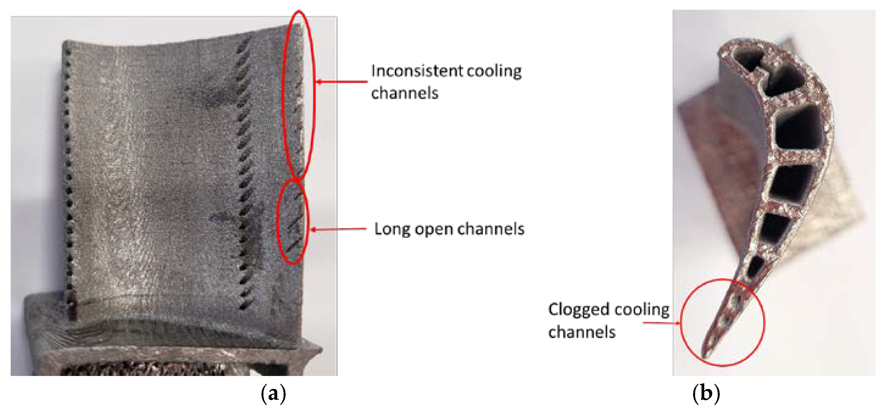
Based on the visual inspection of the additive manufactured models, it can be said that the cooling channels from the leading and trailing edges were not manufactured correctly, as can be observed from the images in
Figure 9. The thickness of the trailing edge is too small to support the 0.5 mm diameter of the cooling channel; therefore, in some areas, they appear as long open channels, not enclosed channels (in
Figure 10, they are presented as a long slit in the material). The diameter of the cooling channels from the leading edge appears to be smaller than the designed 0.5 mm value. Furthermore, there is a possibility of being clogged with unmelted powder particles attached during the manufacturing process. Thereby, as a preliminary conclusion, the leading edge and trailing edge cooling channels are not feasible in this configuration; higher diameter cooling channels should be designed in the areas where it is possible (to overcome the SLM manufacturing process limitations) and to increase the thickness of the trailing edge of the airfoil if such cooling channels are used.
There are several factors behind the development of such defects during the SLM manufacturing process, particularly in such small and complex geometries. For example, localized heat accumulation in narrow or enclosed channels leads to elevated temperatures and melt pool instability. Within reduced dimension cooling channels (0.5 mm in diameter), the heat dissipation is limited, resulting in excessive remelting or widening of the melt pool beyond the intended boundaries. This often causes unwanted powder adhesion or partial melting/sintering of powder particles, especially near channel entrances. Even without direct laser exposure, residual heat from adjacent scans can induce powder agglomeration in small channels, obstructing flow paths.
Additionally, laser-material interaction dynamics can vary in the case of complex geometries, such as turbine blades with internal cooling channels. Inside small channels, the laser beam can interact differently with the material (in a less optimal manner, at different angles, or can undergo reflections), creating hotspots. These variations have a great influence on the energy absorption and promote uneven melting, further causing defects such as balling, sputtering, and lack of fusion defects.
These mechanisms highlight the critical importance of optimization of designs and process parameters to obtain high-quality SLM-manufactured parts.
Nowadays, the published research results regarding additively manufactured turbine blades and the limitations imposed by the manufacturing technology or defects that resulted are limited. Studies have been conducted regarding the optimal configurations of cooling channels performed by simulations [
38,
39], but not experimentally; therefore, there is no data available for comparison in the case of such small gas turbine component geometries.
The dimensional analysis results are presented in
Figure 10 and
Figure 11 for the entire turbine blade conceptual model and for the cross-section. Colored maps were obtained by comparing the scanned SLM-manufactured model with the 3D CAD model.
Based on the colored dimensional maps that contain the dimensional accuracy deviations identified, it can be said that the entire turbine blade conceptual model does not present significant dimensional deviations in the as-printed state. Only a few deviations under ±0.135 mm were measured, with the majority being under ±0.100 mm, except for some areas from the top of the airfoil and in the platform area where deviations lower than +0.250 mm were measured. However, these areas can be easily machined to remove the excess material. In the case of the cross-section part additively manufactured, the deviations are more significant than those measured on the entire turbine blade. Deviations between −0.330 mm and +0.250 mm were measured for the SLM-manufactured turbine blade cross-section. The most negative values measured were in the airfoil area, and it is believed that these deviations were caused by shrinkage and deformation during the manufacturing process due to the reduced thickness of the airfoil walls.
Overall, the deviations recorded were acceptable for metallic parts additively manufactured. Gruber et al. [
40] compared the dimensional accuracy and tolerances of powder bed-based and nozzle-based additive manufacturing processes by 3D scanning and CT scanning, and the results obtained by using the two techniques showed a high consistency in the range of ±100 μm between the results. The deviations encountered on the laser powder bed fusion-manufactured metallic demonstrator were in the range of 0.01–0.200 mm, which is consistent with our recorded values. Cuesta et al. [
41] found out that in the case of the Direct Metal Printing process of stainless-steel cubes manufactured using the ProX 100 machine, some dimensional corrections (compensation of the 3D model) should be performed to enhance the accuracy of the parts. It can be concluded that even in simple configurations, the AM technology has some flaws regarding the accuracy of the manufactured parts. Monzon et al. [
42] highlighted the lack of standards to support consistent data inputs regarding the models and simulation processes that can be applied to improve the dimensional accuracy of parts, process capabilities, distortion, and surface finish to optimize build orientation, criteria for convergence time, accuracy calibration, and comparison of machine performance. This conclusion is also supported by other authors [
43,
44].
In
Table 1 and
Table 2 are given the values recorded for the Ra and Rz roughness in the case of the airfoil of the turbine blade conceptual model and in the case of the cross-section in the as-printed state, without surface improvement, while
Figure 12 presents a graphical representation of the average Ra and Rz results measured.
Based on the results obtained, it can be stated that on the pressure side parallel to the building direction, an average Ra of 12.51 μm (average between measurements type I and III) and an average Rz of 77.01 μm (average between measurements type I and III) were obtained, while slightly higher values were measured perpendicular to the building direction Ra = 15.51 μm, respective Rz = 77.06 μm, and lower values were measured diagonally Ra = 11.82 μm, respective Rz = 64.79 μm.
On the suction side, parallel to the building direction, an average Ra of 11.79 μm (average between measurements type VII and VIII) and an average Rz of 76.14 μm (average between measurements type VII and VIII) were obtained, while slightly lower values were measured perpendicular to the building direction Ra = 13.89 μm, respective Rz = 74.84 μm, and higher values were measured diagonally Ra = 12.82 μm, respective Rz = 67.29 μm.
Lower values were measured on the suction side of the cross-section of the turbine blade conceptual model. Parallel to the building direction, an average Ra of 11.02 μm (average between measurements type VII and VIII) and an average Rz of 67.63 μm (average between measurements type VII and VIII) were obtained, while perpendicular to the building direction, Ra = 12.07 μm, and Rz = 62.48 μm, and diagonally, Ra = 12.69 μm and Rz = 66.85 μm.
The results obtained for the two pieces did not show any significant differences. The Ra values obtained are close to the maximum roughness value of forged parts (Ra = 3.2–12.5 µm) and the minimum roughness value of sand cast parts (Ra = 12.5–25 µm) [
45]. However, to use the experimental model in service, the surface should be prepared using sandblasting or other processes that would lead to a reduction in surface roughness. However, the part could be used in the as-printed state if thermal barrier coatings (TBCs) are applied, as a high roughness favors the adhesion of the bond coat. Chen et al. [
46] showed that the roughness of SLM-manufactured Ti-6Al-4V depends on the position of the building plate and the surface inclination. In another study published by the authors [
47] on Inconel 625 manufactured samples, it was proved that the process parameters have a significant influence on the roughness and density of the material. The Ra values obtained in the current study are consistent with the results obtained in the case of SLM-manufactured parts by Yasa and Kruth (Ra = 12 μm with a 2 μm standard deviation) [
48]. Bernevig-Sava et al. [
49] obtained Ra values in the range of 8.62–15.04 μm for unsandblasted SLM-manufactured Co-Cr samples and in the range of 5.23–14.35 μm for sandblasted SLM-manufactured Co-Cr samples. They showed that the roughness was caused by the balling effect.
The liquid penetrant testing was performed by hanging both the entire turbine blade and the cross-section on a metallic rack and spraying all the elements of the liquid penetrant testing kit. Other authors reported using this method for the investigation of cracks produced in SLM-manufactured samples [
50,
51].
The obtained results are presented in the images from
Figure 13. Based on these images, it can be said that the additively manufactured parts do not have open discontinuities on the surface (cracks, pores, or lack of fusion defects) that resulted during the manufacturing process. From
Figure 11, it can be observed that in the case of the entire turbine blade, the red penetrant dye emerged from the cooling channels; it was not considered a defect as the dye penetrated the orifices during the removal process. The same case was registered in the area of the root of the turbine blade, as it was not mechanically prepared and the penetrant infiltrated the remaining support material.
The same configuration of the turbine blade conceptual model was updated, the diameter of the cooling channels from the leading and trailing edges was increased from 0.5 mm to 1 mm, and a new manufacturing trial was performed just to see if the same defects appeared. The conceptual model of the turbine blade on the building plate and after the removal of the support is presented in
Figure 14.
Based on this new experiment, it was concluded that the cooling channels from the leading edge were manufactured correctly but had a lower diameter than the diameter imposed (were 0.5 mm compared with the 1 mm imposed), but the same defect was encountered at the trailing edge cooling channels, as can be seen in
Figure 15. Furthermore, the last three cooling channels on the top of the airfoil were clogged with unmelted powder during the manufacturing process.
Based on all the experimental results obtained, it can be stated that turbine blades with cooling channels can be manufactured successfully using metal additive manufacturing technology, but increased attention should be paid to the designing phase of the turbine blade. In the current case, the trailing edge of the turbine blade should be re-evaluated and redesigned to allow the correct manufacturing of the cooling channels.
4. Conclusions
During the present research, a turbine blade conceptual model integrating internal cooling channels was designed and developed using additive manufacturing technology, namely, the SLM process. The optimum manufacturing orientation was assessed by simulation using the internal preparation program of the SLM machine as well as by numerical simulation using Ansys software. It was concluded that even if the manufacturing time was higher, the best results could be obtained by manufacturing the part in the vertical position, as in this orientation the support material and the distortion degree are minimal. Two configurations of the model were manufactured: an entire turbine blade conceptual model and a cross-section in the turbine blade conceptual model. After manufacturing the two parts, non-destructive analyses were performed, consisting of dimensional accuracy measurements by 3D laser scanning, surface quality analyses by roughness measurements in various directions and faces, and liquid penetrant testing to detect open discontinuities on the surface resulting from the manufacturing process.
The preliminary visual inspection of the models revealed that the cooling channels from the leading and trailing edges were not manufactured correctly, as the thickness of the trailing edge was too small to support the 0.5 mm diameter of the cooling channel. The diameter of the cooling channels from the leading edge is smaller than the designed 0.5 mm value and can be clogged with unmelted powder particles during the manufacturing process.
The dimensional accuracy deviations are acceptable for metal parts manufactured by SLM; higher deviations were recorded in the case of the cross-sectional part, as they were caused by shrinkage and deformation during the manufacturing process due to the reduced thickness of the airfoil walls.
Average roughness values Ra between 11.02 μm and 15.51 μm, respective Rz between 62.48 μm and 77.06 μm were recorded depending on the area and direction of the measurements, values that were consistent with the results reported in the literature for metal AM.
The liquid penetrant testing revealed that the additive manufactured parts do not have open discontinuities on the surface, such as cracks, pores, or lack-of-fusion defects that could result during the manufacturing process.
Overall, the SLM process can be applied for the manufacturing of turbine blades with internal cooling channels, but significant attention should be paid during the designing phase, and because of the limitations of the process, some features of the turbine blade design were not manufactured correctly (the holes of 0.5 mm were stuck with powder, and the trailing edge of the blade was too thin to ensure the proper manufacturing of the cooling channels from this area). Future studies will be conducted regarding topology optimization of the turbine blade cooling channels to maximize the heat transfer while ensuring manufacturability and providing an increase in the internal cooling surface. Additionally, the future studies will be conducted on proper alloys for turbine blades, namely a Ni-based superalloy—Inconel 718.


 ,
, 


