Article

Cobot Kinematic Model for Industrial Applications

Department of Civil and Mechanical Engineering, University of Cassino and Southern Lazio, Via G. Di Biasio 43, 03043 Cassino, Italy
*
Author to whom correspondence should be addressed.
Inventions 2025, 10(3), 37; https://doi.org/10.3390/inventions10030037
Submission received: 4 April 2025 / Revised: 19 May 2025 / Accepted: 20 May 2025 / Published: 22 May 2025
(This article belongs to the Section Inventions and Innovation in Advanced Manufacturing)

Abstract

In this paper, a specific parametric and open-source algorithm for the direct and inverse kinematics of the UR5e Cobot is formulated by using the (n, o, a, p) transformation matrix, along with the inverse matrices, and then implemented in Matlab for numerical validation purposes. Thus, a specific robotized cell that includes novel mechatronic devices has been designed and built at LARM (Lab. of Robotics and Mechatronics) in Cassino in order to experimentally validate the proposed algorithm. In particular, many experimental points to carry out the whole automatic cycle have been detected by using the corresponding teach-pendant tool and joint positions for different UR5e Cobot poses. In addition, this consistent experimental campaign has allowed to evaluate the percentage accuracy of the robot, which can be useful for the practical applications. Therefore, the proposed kinematic model, along with the parametric and open-source algorithm, of the UR5e Cobot can be useful to simulate different applications in several robotized cells with a good reliability with respect to the real program of the robot.

1. Introduction

In recent decades, the manufacturing industry has evolved significantly with the adoption of new technologies, with collaborative robots (Cobots) emerging as a prominent innovation. Unlike traditional robots designed for repetitive or hazardous tasks in isolated settings, Cobots are engineered to work in close collaboration with human operators. This capability enhances workplace safety, operational flexibility, and productivity, making Cobots suitable for a variety of industrial applications [1]. Reviews have highlighted Cobots advanced human interaction capabilities, their compliance with safety standards, and their roles in current industrial applications, stressing the importance of proper deployment strategies for maximum efficiency [2,3]. The integration of ergonomic design and human factors is essential to optimize Cobot implementation, ensuring safe and productive human-robot interaction [3]. Cobots contribute significantly to smart manufacturing and Assembly 4.0, where they enhance efficiency, reduce downtime, and minimize operational costs [4,5]. The challenges associated with designing and controlling hybrid human-robot systems have been thoroughly studied, with solutions proposed to improve their practical application [6]. Cutting-edge developments, such as brain-computer interfaces, are being explored to improve communication and control between humans and Cobots, promoting intuitive and user-friendly interfaces [7]. Future roadmaps emphasize the necessity of strong safety protocols and seamless interaction systems for continued human-robot collaboration [8]. Optimizing the performance of robotic manipulators is vital for improving Cobot efficiency. Research has shown that the optimization of serial robotic systems, including tendon-driven 4R planar arms, can lead to enhanced flexibility and operational effectiveness [9,10]. Parallel robots have also benefited from technological advancements, as demonstrated through the experimental validation of the CaPaMan (Cassino Parallel Manipulator) as an earthquake simulator, showcasing their application in complex dynamic scenarios [11,12]. The precision and stability of robotic systems have been enhanced through the mechatronic design and sophisticated control of 3-RPS parallel manipulators, reflecting substantial progress in the field [13]. Cobots have also made significant advancements in the medical and rehabilitative sectors. Reviews underline their potential to improve patient care, reduce the workload of healthcare professionals, and enhance overall treatment outcomes [14]. During the COVID-19 pandemic, Cobots were effectively used to minimize healthcare workers’ exposure risks [15]. Systematic reviews in nursing have pinpointed existing applications and gaps that require further research to expand their use in patient care [16]. The development of robotic skin technology has contributed to safer and more immersive interactions, improving teleoperation and emotional engagement between users and robotic systems [17]. In the realm of Healthcare 4.0, Cobots are envisioned to play a crucial role in homecare, providing personalized support and improving the quality of life for patients [18]. Rehabilitation robotics, focusing on upper limb assistance and cooperative control strategies, have demonstrated improvements in therapeutic efficacy and the optimization of exoskeleton performance [19,20,21]. Safety is a paramount concern in human-robot interactions: reviews emphasize the critical need for stringent safety protocols and industry standards to prevent accidents and ensure reliable integration [22]. The role of Cobots in Industry 4.0 is transformative, as they offer increased productivity, adaptability, and flexibility [23]. The anticipated shift towards Industry 5.0 highlights the potential advantages of Cobots over traditional industrial robots, emphasizing their importance in future human-centric manufacturing systems [24].
Recent advancements in kinematic modelling have significantly enhanced the precision and flexibility of robotic systems. A validated method for inverse kinematics in 6-DOF (degree of freedom) industrial robots with offset and spherical joints offers interactive tools for real-time control [25]. Additionally, a kinematic model for a 6-DOF manipulator has been experimentally validated, providing a solid foundation for offline programming and calibration [26]. In collaborative robotics, new kinematic models address both direct and inverse kinematics in shared human-robot tasks, improving system efficiency [27]. For medical applications, an innovative closed-form solution for inverse kinematics in puncture robotics enhances surgical accuracy and optimizes workspace configurations [28]. A versatile kinematic analysis for open architecture 6R robot controllers allows for adaptable models across various robot types, proving accurate in both forward and inverse kinematics [29]. In ecological applications, an improved algorithm for a Tree-Planting Robot significantly enhances trajectory planning and reduces deviation [30]. Furthermore, a comparative study of kinematic analysis methods using the KUKA manipulator shows that particle swarm optimization achieves the highest accuracy, while RoboAnalyzer is the fastest, highlighting the importance of method selection [31]. Moreover, innovations in 5-DoF robot designs combining prismatic and revolute joints have shown potential in replacing traditional 6-DoF robots with greater efficiency and cost-effectiveness [32]. Lastly, improvements in trajectory optimization algorithms, such as an enhanced chicken swarm algorithm, have been validated to improve convergence speed, solution accuracy, and stability in robotic arm applications [33].
Human-robot interaction has become increasingly important in the context of collaborative robotics, where precise control strategies are essential for effective task execution. In particular, force control techniques play a critical role in ensuring stability and adaptability in dynamic and unstructured environments, as demonstrated in recent studies on rough terrain locomotion [34] and horizon-stability control for wheel-legged robots [35].
Thus, although several kinematic models of 6R serial manipulators can be found in literature, instead to merely use commercial and/or available software packages, as RoboDK [27], RoboAnalyzer and Peter Corke Toolbox [31], in this paper, a specific parametric and open-source algorithm for the direct and inverse kinematics of a UR5e Cobot has been formulated and implemented in Matlab, with the aim to analyze the UR5e Cobot kinematic performance for simulation purposes of industrial applications. Moreover, in order to obtain a reliable algorithm, this has been experimentally validated in terms of direct and inverse kinematics, by using a UR5e Cobot and reading the corresponding tool and joint positions by the tech-pendant for several robot poses.
Finally, a specific industrial application regarding the robotized assembling of a multi-cylinder IC engine has been designed in terms of layout, built and experimentally tested. In particular, the IC engine in scale of 1:5 and specific parts of the end-effector, which takes the role of vacuum gripper and torque limiting screwdriver, have been designed and manufactured by using a 3D printer. Thus, the main contributions are:
  • a suitable parametric and open-source algorithm is formulated by using the inverse matrices only;
  • this algorithm has been implemented in Matlab, and a numerical validation has been carried out;
  • a specific robotized cell that includes novel mechatronics devices has been designed and built at LARM (Lab. of Robotics and Mechatronics) in Cassino;
  • the proposed algorithm has been also experimentally validated;
  • the accuracy percentage of the Cobot UR5e has been determined.
The remainder of this paper is structured as follows: Section 1 introduces the back-ground and motivation for the proposed kinematic model and algorithm. Section 2 pre-sents the kinematic model of the UR5e Cobot, including both direct and inverse kinemat-ics formulations. Section 3 describes the experimental setup for the robotized work cell, including the design, implementation, and testing of the multi-cylinder IC engine assem-bly. Finally, Section 4 concludes the paper, summarizing the main contributions and the experimental validation results.

2. Materials and Methods

The Cobot kinematic model is formulated by using the standard D-H method to define the coordinate system that is attached to each link of the serial chain, along with the four corresponding D-H parameters. Thus, the total homogeneous transformation matrix is obtained between the end-effector moving frame and the fixed base frame.
The direct kinematics (DK) problem is crucial for developing manipulator algorithms, because the joint positions are typically measured by the corresponding sensors, which give the relative position between two consecutive links. Thus, the DK problem is solved by calculating the homogeneous transformation matrix between the end-effector moving frame and the fixed base frame. On the other hand, the inverse kinematics (IK) can be developed by determining the joint variable as function of a given end-effector configuration.
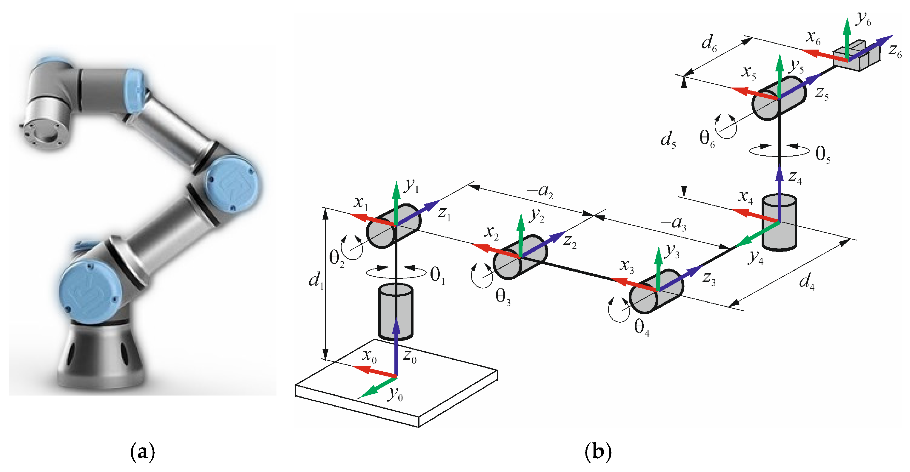
Figure 1 shows a typical 6R serial kinematic chain of 6 (DOFs), which also corresponds to that of the UR5e robotic arm (Figure 1a), along with D-H reference frames (Figure 1b). In particular, the fixed frame x0y0z0 is attached to the robot base, while the i-th moving frame xiyizi is considered as attached to the i-th link for i = 1, …, 6, where the zi-axis is along the joint axis direction, the xi-axis is perpendicular to both zi and zi−1 axis, and the yi-axis is chosen in agreement with the right-hand rule.
The D-H parameters are reported in Table 1, where θi represents the joint angle variable of each UR5e joint, di is the offset of the link, ai denotes the length of the link, αi indicates the joint torsion angle, where i = 1, …, 6 is the joint number.
Thus, the homogeneous transformation matrix between the D-H reference frames that are associated to the joints i − 1 and i, takes the form
T i i 1 = cos θ i cos α i sin θ i sin α i sin θ i a i cos θ i sin θ i cos α i cos θ i sin α i cos θ i a i sin θ i 0 sin α i cos α i d i 0 0 0 1

2.1. Direct Kinematics

The DK problem for a serial kinematic chain consists of finding the position and orientation of the end-effector moving reference frame, when all the joint angles θi (i = 1, …, 6) are given. Referring to Table 1 and Equation (1), the D-H homogeneous transformation matrices are obtained as follows
T 1 0 = c 1 0 s 1 0 s 1 0 c 1 0 0 1 0 d 1 0 0 0 1 T 2 1 = c 2 s 2 0 a 2 c 2 s 2 c 2 0 a 2 s 2 0 0 1 0 0 0 0 1 T 3 2 = c 3 s 3 0 a 3 c 3 s 3 c 3 0 a 3 s 3 0 0 1 0 0 0 0 1 T 4 3 = c 4 0 s 4 0 s 4 0 c 4 0 0 1 0 d 4 0 0 0 1 T 5 4 = c 5 0 s 5 0 s 5 0 c 5 0 0 1 0 d 5 0 0 0 1 T 6 5 = c 6 s 6 0 0 s 6 c 6 0 0 0 0 1 d 6 0 0 0 1
where ci and si (i = 1, …, 6) stand for cos θ i and sin θ i , respectively.
Consequently, the direct kinematics solution is obtained by multiplying in sequence and among them, the six homogeneous transform matrices of the Equation (2), by giving the following T 6 0 resultant matrix
T 6 0 = T 1 0   T 2 1   T 3 2   T 4 3   T 5 4   T 6 5
This can be considered equal to the following 4 × 4 matrix
T 6 0 = n x o x a x p x n y o y a y p y n z o z a z p z 0 0 0 1
that includes the noa rotation matrix, whose entries are the Cartesian components of the corresponding unit vectors n, o, and a, respectively, while (px, py, pz) are those of the tool position vector p.
Thus, equating the corresponding entries of the matrices of Equation (4), one has
n x = s 1 s 5 c 6 + c 1 c 234 c 5 c 6 s 234 s 6 n y = s 1 c 234 c 5 c 6 s 234 s 6 c 1 s 5 c 6 n z = c 234 s 6 + s 234 c 5 c 6 o x = s 1 s 5 s 6 c 1 c 234 c 5 s 6 + s 234 c 6 o y = s 1 c 234 c 5 s 6 + s 234 c 6 + c 1 s 5 s 6 o z = c 234 c 6 s 234 c 5 c 6 a x = s 1 c 5 c 1 c 234 s 5 a y = s 1 c 234 s 5 c 1 c 5 a z = s 234 s 5 p x = s 1 d 4 + d 6 c 5 c 1 d 6 c 234 s 5 + a 2 c 2 d 5 s 234 + a 3 c 23 p y = s 1 d 6 c 234 s 5 a 2 c 2 + d 5 s 234 a 3 c 23 c 1 d 4 + d 6 c 5 p z = d 1 a 3 s 23 a 2 s 2 d 5 c 23 c 4 s 23 s 4 d 6 s 5 c 23 s 4 + s 23 c 4
where s and c stand for sine and cosine, respectively, and one has c 23 = cos ( θ 2 + θ 3 ) , s 23 = sin ( θ 2 + θ 3 ) , c 234 = cos ( θ 2 + θ 3 + θ 4 ) and s 234 = sin ( θ 2 + θ 3 + θ 4 ) .

2.2. Inverse Kinematics

The IK problem for a serial kinematic chain consists of finding the joint angles θi (i = 1, …6) of the serial kinematic chain, when the position and orientation of the end-effector is given in terms of the [n o a p] homogeneous transformation matrix. The required end-effector pose is given by the Equation (4) and thus, multiplying each side of it by the inverse matrix T 1 1 0 , it obtains the following matrix equation
T 6 1 = T 1 1 0 n x o x a x p x n y o y a y p y n z o z a z p z 0 0 0 1
where T 6 1 is given by T 6 1 = T 2 1   T 3 2   T 4 3   T 5 4   T 6 5 and one has
T 6 1 = c 234 c 5 c 6 s 234 s 6 s 234 c 6 c 234 c 5 s 6 c 234 s 5 a 2 c 2 a 3 c 23 d 5 s 234 d 6 c 234 s 5 c 234 s 6 + s 234 c 5 c 6 c 234 c 6 s 234 c 5 s 6 s 234 s 5 a 2 s 2 a 3 s 23 d 5 c 234 d 6 s 234 s 5 s 5 c 6 s 5 s 6 c 5 d 4 + d 6 c 5 0 0 0 1
Similarly, developing the right side of Equation (6), one has
T 6 0 = n x c 1 + n y s 1 o x c 1 + o y s 1 a x c 1 + a y s 1 p x c 1 + p y s 1 n z o z a z p z d 1 n x s 1 n y c 1 o x s 1 o y c 1 a x s 1 a y c 1 p x s 1 p y c 1 0 0 0 1
The joint angles θi for i = 1, …, 6 are obtained by equating the right sides of the Equations (7) and (8), excluding the fourth row, and thus obtaining a system of 12 non-linear equations, which are coupled two by two, in order to obtain six subsystems of two equations for each. In particular, developing the first subsystem, which is obtained by equating the two entries of the third row with the columns three and four, θ1 is given by
θ 1 = atan 2 d 4 , ± a y d 6 p y 2 + p x a x d 6 2 d 4 2 atan 2 a y d 6 p y , p x a x d 6
Likewise, the joint angles θ5 and θ6 are obtained by equating the two entries of the third row with the columns one and two. One has
θ 5 = atan 2 ± n x s 1 n y c 1 2 + o x s 1 o y c 1 2 , a x s 1 a y c 1
θ 6 = atan 2 o x s 1 o y c 1 s 5 , n x s 1 n y c 1 s 5
The joint angle θ234 is obtained by equating the two entries of the first and second rows with the column three and after a suitable development, one has
θ 234 = θ 2 + θ 3 + θ 4 = atan 2 a z s 5 , a x c 1 + a y s 1 s 5
Similarly, the joint angles θ2 and θ23 are obtained by equating the first and second rows with the fourth column and thus, one has
θ 2 = atan 2 a 3 2 a 2 2 A 2 B 2 2 a 2 A 2 + B 2 , ± 1 a 3 2 a 2 2 A 2 B 2 2 a 2 A 2 + B 2 2 atan 2 A , B
θ 23 = atan 2 B a 2 s 2 a 3 , A a 2 c 2 a 3
where the coefficients A and B are expressed as follows
A = p x c 1 + p y s 1 d 5 s 234 + d 6 c 234 s 5 B = p z d 1 + d 5 c 234 + d 6 s 234 s 5
Finally, referring to Equations (12)–(14), the joint angles θ3 and θ4 are given by
θ 3 = θ 23 θ 2
θ 4 = θ 234 θ 23

2.3. Experimental Validation for One Pose

The proposed algorithms for solving the inverse and direct kinematics of the UR5e Cobot have been experimentally validated by referring to an arbitrary Cobot reference pose, which is given by the teach pendant in terms of the tool position vector p and the rotation vector r, along with the joint angles θi for i = 1, …, 6, respectively. Vectors p and r have Cartesian components with respect to the base frame of (px, py, pz) and (rx, ry, rz), respectively. In particular, the rotation vector r of magnitude ϕ, define the rotation axis of the tool end-effector, along with the corresponding rotation angle ϕ, which is not a joint angle, since referred to the axis of unit vector u. In fact, one has
ϕ = r x 2 + r y 2 + r z 2
u = 1 ϕ r x r y r z
where rx, ry and rz are the Cartesian components of r with respect to base frame.
Consequently, the homogeneous transformation matrix T 6 0 , which includes the noa rotation matrix that corresponds to a given rotation vector r of magnitude ϕ and unit vector u, along with the tool position vector p, can be expressed as follows
T 6 0 = u x 2 1 c ϕ + c ϕ u x u y 1 c ϕ u z s ϕ u x u z 1 c ϕ + u y s ϕ p x u x u y 1 c ϕ + u z s ϕ u y 2 1 c ϕ + c ϕ u y u z 1 c ϕ u x s ϕ p y u x u z 1 c ϕ u y s ϕ u y u z 1 c ϕ + u x s ϕ u z 2 1 c ϕ + c ϕ p z 0 0 0 1
Therefore, referring to Table 2 that contains the experimental Cartesian components of vectors p and r for the assigned UR5e Cobot pose, applying Equations (18) and (19) to determine the rotation angle ϕ = 3.111 rad and the unit vector u = 0.7071 0.7071 0.0064 , and finally substituting in Equation (20), one has
T 6 0 = 0.0002 0.9999 0.0123 135.0 0.9995 0.0002 0.0305 292.1 0.0305 0.0123 0.9995 523.8 0 0 0 1
According to the proposed IK algorithm, the assigned experimental Cartesian components of p and r of Table 2, the corresponding joint angles θi for i = 1, …6 are reported in Table 3, as follows
Likewise, the DK is solved by using as input data, the joint angles θi for i = 1, …6 of Table 3, which are substituted into the Equation (2) in order to obtain the whole homogeneous transformation matrix T 6 0 of Equation (3), as follows
T 6 0 = 0.0000 0.9999 0.0119 135.1514 0.9996 0.0003 0.0280 292.2861 0.0280 0.0119 0.9995 523.2706 0 0 0 1
However, the teach pendant of the UR5e Cobot gives the tool end-effector pose in terms of p and r components, for which, the following matrix is introduced
T 6 0 = r 13 r 12 r 13 p x r 21 r 22 r 23 p y r 31 r 32 r 33 p z 0 0 0 1
where the first three numbers of the fourth column of Equation (22) correspond to the Cartesian components of vector p, respectively.
Developing Equation (23), one has
ϕ = cos - 1 r 11 + r 22 + r 33 1 2
u = 1 2 s ϕ r 32 r 23   r 13 r 31   r 21 r 12 T
and thus, the rotation vector r is given by
r = ϕ u x   u y   u z
which numerical results, along with p, are reported in Table 4, as follows
This experimental validation procedure of the proposed algorithm for the UR5e Cobot direct and inverse kinematics is extensively applied in the next session by referring to the robotized assembling of a multi-cylinder IC engine. Particular attention will be devoted to the first Operation of the whole automatic cycle and then all Cobot poses will be also considered for the validation purposes of the proposed kinematic model.
3. Results and Discussion

A specific industrial application regarding the robotized assembling of a multi-cylinder IC engine has been designed in terms of layout and corresponding automatic cycle that is intended as a sequence of the robot elementary actions. In particular, the proposed robotized cell is composed by the UR5e Cobot along with its controller and a suitable electropneumatic circuit that includes a PLC with its user interface, which are both governed by means of a specific electronic board and a switch control box.
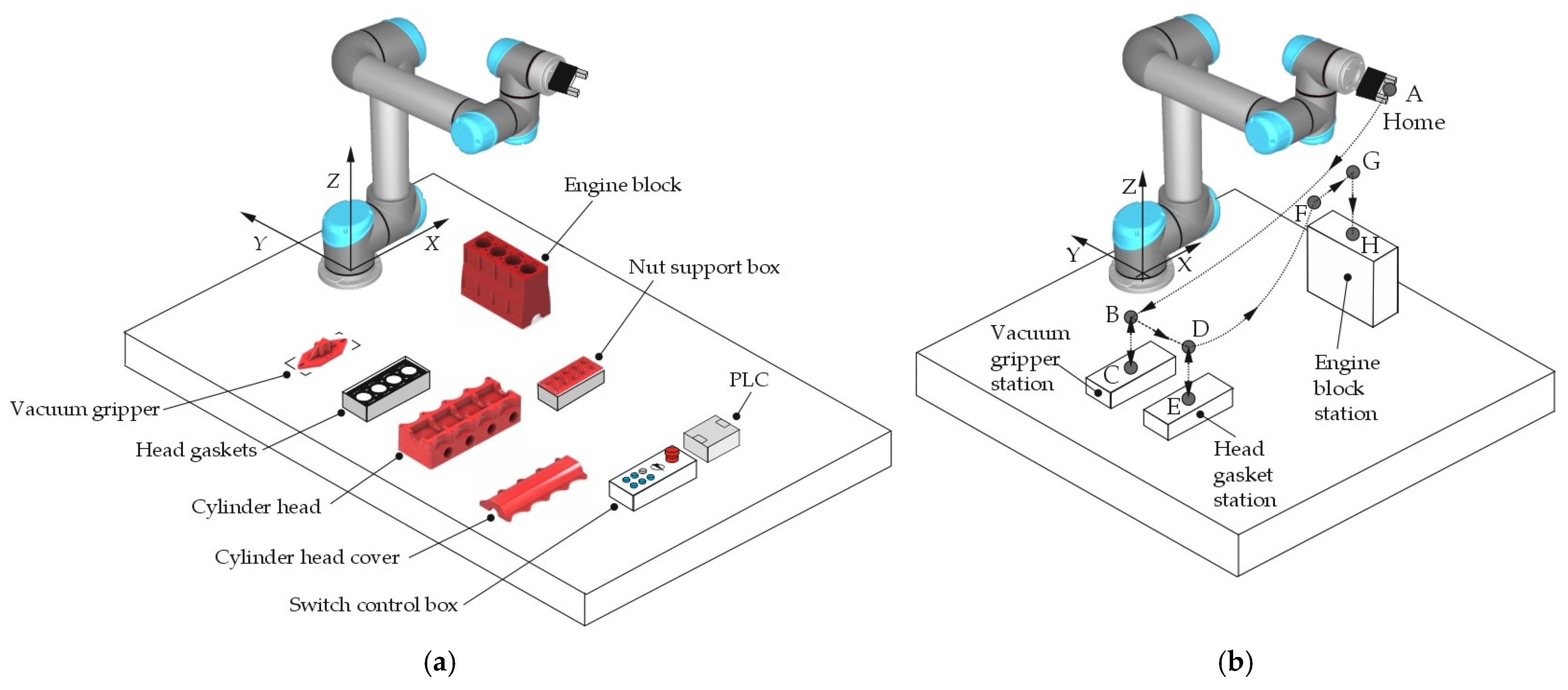
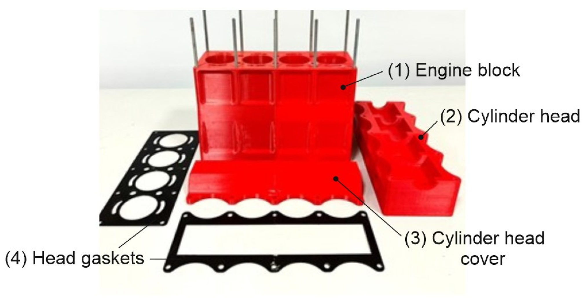
Referring to Figure 2, the robotized assembling of a multi-cylinder IC engine is carried out by means of a suitable automatic cycle and in agreement with the main engine components, which are: (1) engine block; (2) cylinder head; (3) cylinder head cover; (4) head gaskets. Consequently, these components are suitably positioned on a working table and in such a way to be reachable by the Cobot end-effector, as sketched in Figure 3a.
The automatic cycle has been conceived of five fundamental operations, where four consist of the assembling of the following components on the engine block that is fixed on the working table: (1) the first head gasket; (2) the cylinder head; (3) the second head gasket; (4) the cylinder head cover. The fifth operation consists of the nut screwing in order to assembly all engine components safely. Moreover, each operation has been distinguished in a suitable number of elementary actions. The proposed Cobot kinematic model has been further validated during a manipulation and not only in a given pose.

3.1. Automatic Cycle: Operation 1

The first operation of the whole automatic cycle is aimed to assemble the first head gasket on the fixed cylinder block, which elementary actions, starting by the home Cobot position (A) and referring to the sketch of Figure 3b, are: (1) the end-effector reaches the position B; (2) it grasps the vacuum gripper in C; (3) it moves back to B; (4) it moves to D; (5) it grasps the first head gasket in E; (6) it moves to F; (7) it moves to G; (8) it assembles the first head gasket on the cylinder block in H. Therefore, referring to Table 5, which contains the Cartesian components of vectors p and r for each Cobot pose, which corresponds to the end-effector position from A to H for the Operation 1, the proposed IK Cobot model has allowed to determine all the corresponding joint angles θi for i = 1, …, 6.
Moreover, the proposed IK Cobot model has been implemented in Matlab by giving the graphical result of Figure 4 for the Operation 1, along with the corresponding joint angles of Table 6. This has allowed the experimental validation of the proposed Cobot kinematic model during a manipulation and not only in a given pose, as in session 2.3.
In fact, referring to the Operation 1 of Figure 3b and the assigned input data of Table 5, the numerical and experimental six joint angles θi for i = 1, …, 6 of the UR5e Cobot have been obtained by the proposed IK Cobot model and the tech-pendant screen, respectively. These results can be correspondingly compared among them, as reported in Table 7, in terms of their relative errors δi (i = 1, …, 6) for each joint angle θi as follows
δ i = θ i e θ i n
where θie and θin are the experimental and numerical joint angles θi for i = 1. …. 6, respectively. Thus, the proposed parametric and open-source algorithm for the direct and inverse kinematics of the UR5e Cobot has been experimentally validated with a good reliability. Moreover, a further validation has been carried out by calculating both the position and the orientation vectors p and r for each joint and pose of the UR5e Cobot, as reported in Table 8 along with the graphical representation of Figure 4, which shows the Cobot kinematic chain in each pose of the Operation 1. In particular, Figure 4a shows a 3D view, while Figure 4b–d show the XY, XZ and the YZ planar views. The same approach has been used to analyze and simulate the other four Operations of the whole automatic cycle, as reported in the next section.

3.2. Automatic Cycle: Operations 2 to 5

Using the same approach that has been applied in Section 3.1 and referring to the Operations 2 to 5, since the first was considered in the previous section, the numerical and the experimental joint angles have been determined with reference to the input data of Table 9 for the end-effector position and the orientation vectors p and r.
According to the UR5e Cobot inverse kinematics. the numerical results in terms of joint angles are reported on the left side of Table 10, while the corresponding experimental results are shown on the right side. A good approximation is obtained by comparing the corresponding numerical and experimental joint angles.
In addition. the MAPE (mean absolute percentage error) has been applied by using the following equation:
M A P E = 1 n θ i e θ i n θ i e 100 %
where n is the number of fitted points.
In particular, the MAPE measures the average magnitude of the error that is produced by a model, or how far off predictions are on average. A low MAPE value indicates a more accurate prediction, while a high MAPE value indicates a less accurate prediction. The percentage of accuracy between the experimental and numerical joint angles θi (i = 1. …. 6) shown in Table 6 and Table 10 is calculated as follows
ε = 100 % M A P E
Thus, a percentage of accuracy of the proposed Cobot kinematic model is 99.84%.
Moreover, the Pj points could for j = 1 to 39, which correspond to the Operations 2 to 5 of the whole automatic cycle of the robotized work cell, are graphically shown in Figure 5, along with the 8 points, from A to H of the Operation 1 for a total of 47 points, which fall inside the Cobot workspace. In particular, the 3D view is shown in Figure 5a, while Figure 5b–d show its XY, XZ and YZ planar projections.

3.3. Experimental Set-Up of the Robotized Work Cell

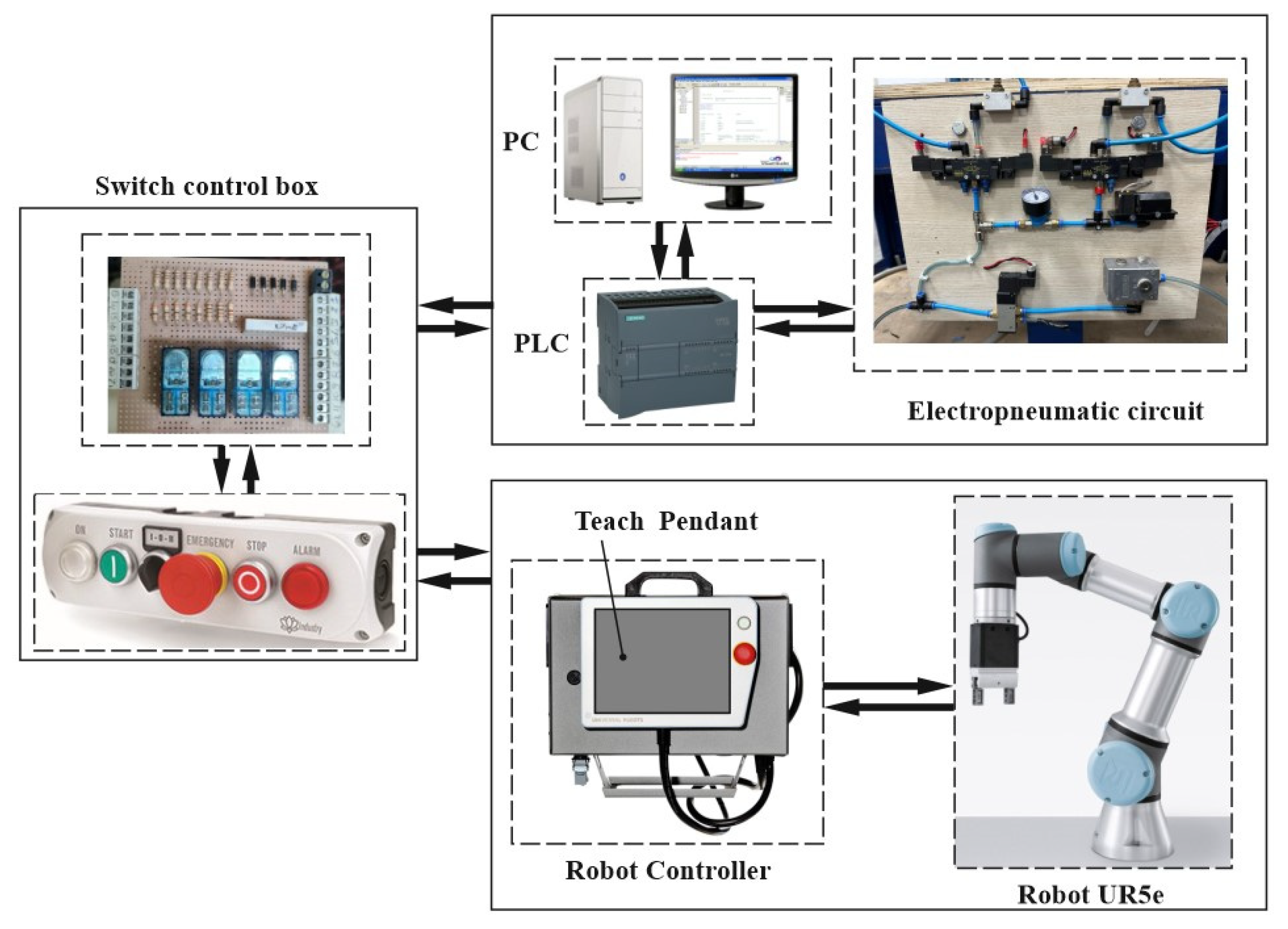
According to the sketch of Figure 3a, the whole robotized work cell for assembling a multi-cylinder IC engine has been designed and built at LARM (Laboratory of Robotics and Mechatronics) of DICEM (Department of Civil and Mechanical Engineering) of the University of Cassino and Southern Lazio. This has required the mechatronic design, along with the building and the assembling of other suitable devices and systems, which cooperate among them and with the UR5e Cobot according to a specific automatic cycle, as reported in Figure 6, Figure 7 and Figure 8.
In particular, the mechatronic scheme of the proposed robotized work cell is shown in Figure 6, where the UR5e Cobot and its controller cooperate with a suitable electropneumatic system that is controlled and programmed through a PLC of Siemens S7-1200 type. Both automatic systems are governed by means of a suitable switch control box, which is installed on the working table.
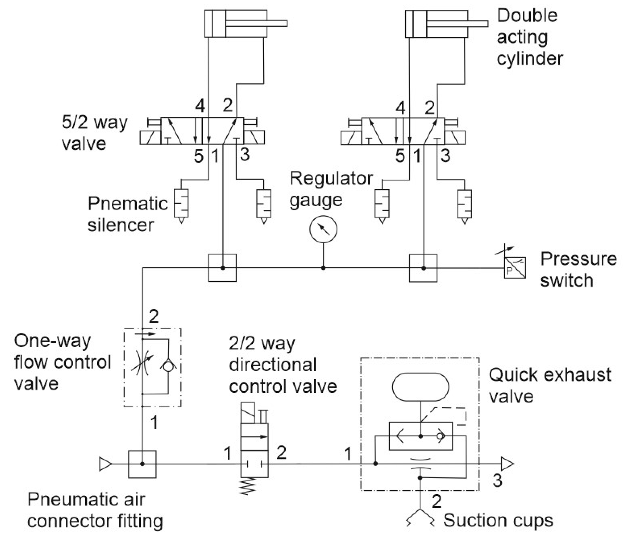
A detail on the electropneumatic circuit is shown in Figure 7, which can be considered as composed by two main parts, where the first part is devoted to perform the vacuum grasp by means of four suction-cups and ejectors (only one is shown in Figure 7), where each of them is provided by a suitable quick exhaust valve, while the second part of the electropneumatic circuit refers to the locking device of the engine block, which is mainly composed by two double-acting pneumatic cylinders, along with their operating electrovalves of 5/2 (five-way/two-positions) type.
Referring to Figure 6, when the operator selects the manual or automatic mode by pressing the suitable starting button, the Cobot controller and the PLC are activated directly and by means of a specific switch control box, respectively. Moreover, the PLC is connected to a PC that is provided with a monitor and keyboard, as user interface, while its I/O electronic board is wired to electrovalves and end-stroke sensors to control the electropneumatic circuit. In particular, the scheme of Figure 7 shows the electropneumatic circuit that is composed by two 5/2 electrovalves, two double-acting cylinders, a pressure switch, and a one-way flow control valve. Moreover, the vacuum gripper is composed of four suction cups, which are actuated by a single ejector with a release device that is operated by a 3/2 electrovalves.
Therefore, the whole robotized work cell for assembling a multi-cylinder IC engine has been experimentally tested at LARM according to the proposed automatic cycle, which is composed of five main Operations.
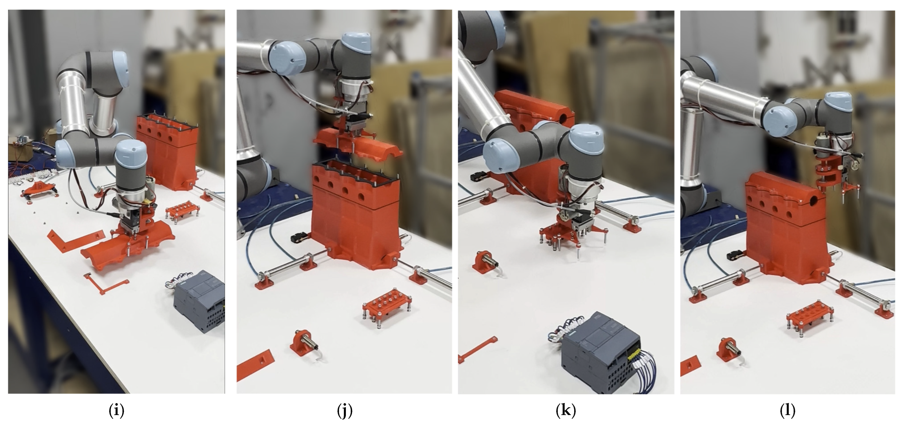
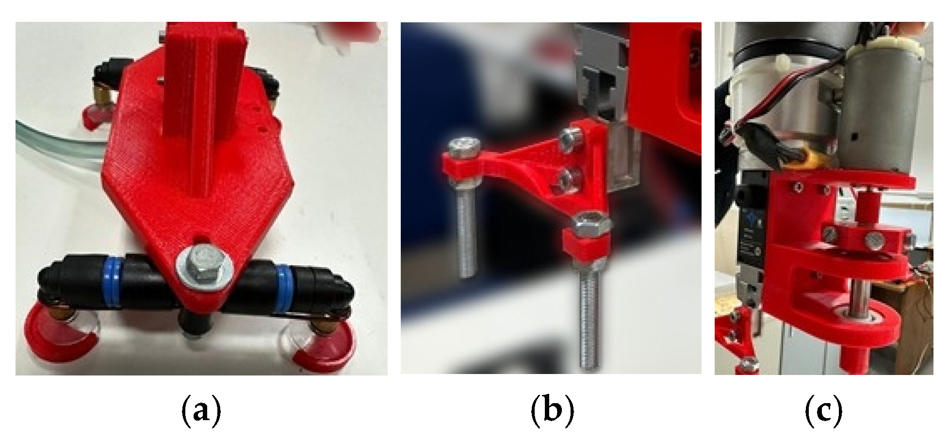
Referring to Figure 8, the Cobot end-effector: grasps the vacuum gripper (Figure 8a); grasps the first head gasket (Figure 8b); assembles it on the cylinder block (Figure 8c); releases the vacuum gripper (Figure 8d); grasps the cylinder head (Figure 8e); assembles the cylinder head by using the two-finger gripper (Figure 8f); grasps the vacuum gripper (Figure 8g); assembles the second head gasket (Figure 8h); release the vacuum gripper and grasps the cylinder head cover (Figure 8i); assembles the cylinder cover on the block (Figure 8j); grasps a nut (Figure 8k); screws one nut for time by using the torque limiting screwdriver (Figure 8l). Moreover, the IC engine in scale of 1:5 and specific parts of the end-effector, have been designed and manufactured by using a 3D printer. Referring to Figure 9, these specific parts consist of the four suction cups of the vacuum gripper (Figure 9a), the two-finger gripper (Figure 9b) and the torque limiting screwdriver (Figure 9c).

4. Conclusions

A specific parametric and open-source algorithm for the direct and inverse kinematics of the UR5e Cobot has been formulated and implemented in Matlab, with the main target to analyze the UR5e Cobot kinematic performance for simulation purposes of industrial applications. Several experimental tests with reference to a specific industrial application for assembling a multi-cylinder IC engine have allowed the validation of the proposed algorithm, demonstrating an accuracy of 99.84%, which confirms its reliability in practical applications. Specific devices for obtaining the end-effector performance, as vacuum gripper and torque limiting screwdriver, have been designed and manufactured by using a 3D printer. The proposed approach and algorithm can be used to simulate and test different robotized cells, which include the UR5e Cobot and electropneumatic systems to perform several industrial applications. However, the current study is limited to a single 6R robot model (UR5e) and does not consider potential sources of error such as sensor drift or mechanical backlash. Future work could focus on extending the proposed algorithm to different robot configurations and integrating real-time optimization techniques to further enhance accuracy and flexibility in dynamic industrial environments.

Author Contributions

Conceptualization, G.F., C.L., and L.T.; Methodology, G.F., C.L., and L.T.; Software, C.L.; Validation, G.F., C.L., and L.T.; Formal analysis, G.F. and C.L.; Investigation, G.F., C.L., and L.T.; Resources, G.F. and L.T.; Data curation, G.F., C.L., and L.T.; Writing—original draft preparation, G.F., C.L., and L.T.; Writing—review and editing, G.F., C.L., and L.T.; Visualization, C.L. and L.T.; Supervision, G.F.; Project administration, G.F.; Funding acquisition, G.F. All authors have read and agreed to the published version of the manuscript.

Funding

This research received no external funding.

Data Availability Statement

The raw data supporting the conclusions of this article will be made available by the authors on request.

Acknowledgments

The authors wish to thank the Master’s students Alessia Ampola, Alessandro Capoccia, Domenico Guida, and Davide Recchia for their technical support in the development of the proposed industrial application at LARM (Laboratory of Robotics and Mechatronics) of DiCEM. University of Cassino and Southern Lazio.

Conflicts of Interest

The authors declare no conflicts of interest.

References

  1. Matheson, E.; Minto, R.; Zampieri, E.G.G.; Faccio, M.; Rosati, G. Human–robot collaboration in manufacturing applications. A review. Robotics 2019, 8, 100. [Google Scholar] [CrossRef]
  2. Taesi, C.; Aggogeri, F.; Pellegrini, N. COBOT Applications—Recent advances and challenges. Robotics 2023, 12, 79. [Google Scholar] [CrossRef]
  3. Faccio, M.; Granata, I.; Menini, A.; Milanese, M.; Rossato, C.; Bottin, M.; Minto, R.; Pluchino, P.; Gamberini, L.; Boschetti, G.; et al. Human factors in Cobot era: A review of modern production systems features. J. Intell. Manuf. 2023, 34, 85–106. [Google Scholar] [CrossRef]
  4. Othman, U.; Yang, E. An Overview of Human-Robot Collaboration in Smart Manufacturing. In Proceedings of the 27th International Conference on Automation and Computing (ICAC), Bristol, UK, 1–3 September 2022; pp. 1–6. [Google Scholar] [CrossRef]
  5. Cohen, Y.; Shoval, S.; Faccio, M. Strategic View on Cobot Deployment in Assembly 4.0 Systems. IFAC-PapersOnLine 2019, 52, 1519–1524, ISSN 2405-8963. [Google Scholar] [CrossRef]
  6. Hashemi-Petroodi, S.E.; Thevenin, S.; Kovalev, S.; Dolgui, A. Operations management issues in design and control of hybrid human-robot collaborative manufacturing systems: A survey. Annu. Rev. Control 2020, 49, 264–276, ISSN 1367-5788. [Google Scholar] [CrossRef]
  7. Dmytriyev, Y.; Zaki, A.M.A.; Carnevale, M.; Insero, F.; Giberti, H. Brain computer interface for human-Cobot interaction in industrial applications. In Proceedings of the 3rd International Congress on Human-Computer Interaction. Optimization and Robotic Applica-tions (HORA), Ankara, Turkey, 11–13 June 2021; pp. 1–6. [Google Scholar] [CrossRef]
  8. Weiss, A.; Wortmeier, A.-K.; Kubicek, B. Cobots in industry 4.0: A roadmap for future practice studies on human–robot collaboration. IEEE Trans. Hum.-Mach. Syst. 2021, 51, 335–345. [Google Scholar] [CrossRef]
  9. Ceccarelli, M.; Lanni, C. Multi objective optimum design of general 3R manipulators for prescribed workspace limits. Mech. Mach. Theory 2004, 39, 119–132, ISSN 0094-114X. [Google Scholar] [CrossRef]
  10. Lanni, C.; Figliolini, G.; D’Angelo, M. Kinematic Synthesis of a Tendon-Driven 4R Planar Robotic Arm. In CISM International Centre for Mechanical Sciences. Courses Lect. 2022, 606, 238–245. [Google Scholar]
  11. Ceccarelli, M.; Carvalho, J.C.M.; Pugliese, F.; Lanni, C. CaPaMan (Cassino Parallel Manipulator) as Sensored Earthquake Simulator. In Proceedings of the International Conference on Robots and Sistems, IROS’99, Kyongju, Republic of Korea; 1999; Volume 3, pp. 1501–1506. [Google Scholar]
  12. Lanni, C.; Pugliese, F.; Ceccarelli, M. An Experimental Validation of CaPaMan as Earthquake Simulator. In Proceedings of the IEEE/ASME Inter-national Conference on Advanced Intelligent Mechatronics AIM’01, Como, Italy, 8–12 July 2001; pp. 153–158. [Google Scholar]
  13. Figliolini, G.; Lanni, C.; Rea, P.; Gallinelli, T. Mechatronic Design and Control of a 3-RPS Parallel Manipulator. In RAAD 2017 Mechanisms and Machine Science; Ferraresi, C., Quaglia, G., Eds.; Advances in Service and Industrial Robotics; Springer: Cham, Switzerland, 2017; Volume 49, pp. 74–81. ISBN 978-3-319-61275-1. [Google Scholar] [CrossRef]
  14. Holland, J.; Kingston, L.; McCarthy, C.; Armstrong, E.; O’Dwyer, P.; Merz, F.; McConnell, M. Service robots in the healthcare sector. Robotics 2021, 10, 47. [Google Scholar] [CrossRef]
  15. Freeman, W.D.; Sanghavi, D.K.; Sarab, M.S.; Kindred, M.S.; Dieck, E.M.; Brown, S.M.; Szambelan, T.; Doty, J.; Ball, B.; Felix, H.M.; et al. Robotics in Simulated COVID-19 Patient Room for Health Care Worker Effector Tasks: Preliminary. Feasibility Experiments. Mayo Clin. Proc. Innov. Qual. Outcomes 2021, 5, 161–170. [Google Scholar] [CrossRef]
  16. Babalola, G.T.; Gaston, J.-M.; Trombetta, J.; Tulk Jesso, S. A systematic review of collaborative robots for nurses: Where are we now. and where is the evidence? Front. Robot. AI 2024, 11, 398140. [Google Scholar] [CrossRef] [PubMed]
  17. Pang, G.; Yang, G.; Pang, Z. Review of robot skin: A potential enabler for safe collaboration. immersive teleoperation. and affective interaction of future collaborative robots. IEEE Trans. Med. Robot. Bionics 2021, 3, 681–700. [Google Scholar] [CrossRef]
  18. Yang, G.; Pang, Z.; Jamal Deen, M.; Dong, M.; Zhang, Y.; Lovell, N.; Rahmani, A.M. Homecare robotic systems for healthcare 4.0: Visions and enabling technologies. IEEE J. Biomed. Health Inform. 2020, 24, 2535–2549. [Google Scholar] [CrossRef]
  19. MajidiRad, A.; Yihun, Y.S. Upper Limb Rehabilitation and Mobility Assistance Using Robotic Devices: A Review. In Proceedings of the ASME 2019 International Design Engineering Technical Conferences and Computers and Information in Engineering Conference. 43rd Mechanisms and Robotics Conference, Anaheim, CA, USA, 18–21 August 2019; Volume 5A, p. V05AT07A039. [Google Scholar] [CrossRef]
  20. Dalla Gasperina, S.; Roveda, L.; Pedrocchi, A.; Braghin, F.; Gandolla, M. Review on Patient-Cooperative Control Strategies for Upper-Limb Rehabilitation Exoskeletons. Front. Robot. AI 2021, 8, 745018. [Google Scholar] [CrossRef]
  21. Chiriatti, G.; Bottiglione, A.; Palmieri, G. Manipulability Optimization of a Rehabilitative Collaborative Robotic System. Machines 2022, 10, 452. [Google Scholar] [CrossRef]
  22. Bogue, R. Robots that interact with humans: A review of safety technologies and standards. Ind. Robot. Int. J. 2017, 44, 395–400. [Google Scholar] [CrossRef]
  23. Sherwani, F.; Asad, M.M.; Ibrahim, B.S.K.K. Collaborative Robots and Industrial Revolution 4.0 (IR 4.0). In Proceedings of the 2020 International Conference on Emerging Trends in Smart Technologies (ICETST), Karachi, Pakistan, 26–27 March 2020; pp. 1–5. [Google Scholar] [CrossRef]
  24. Sahan, A.S.M.; Kathiravan, S.; Lokesh, M.; Raffik, R. Role of Cobots over Industrial Robots in Industry 5.0: A Review. In Proceedings of the 2nd International Conference on Advancements in Electrical. Electronics. Communication. Computing and Automation (ICAECA), Coimbatore, India, 16–17 June 2023; pp. 1–5. [Google Scholar] [CrossRef]
  25. Galin, R.; Meshcheryakov, R.; Samoshina, A. Mathematical Modelling and Simulation of Human-Robot Collaboration. In Proceedings of the 2020 International Russian Automation Conference (RusAutoCon), Sochi, Russia, 6–12 September 2020; pp. 1058–1062. [Google Scholar] [CrossRef]
  26. Dikmenli, S. Forward & Inverse Kinematics Solution of 6-DOF Robots Those Have Offset & Spherical Wrists. Eurasian J. Sci. Eng. Technol. 2022, 3, 14–28. [Google Scholar]
  27. Li, L.; Huang, Y.; Guo, X.X. Kinematics modelling and experimental analysis of a six-joint manipulator. J. Eur. Syst. Autom. 2019, 52, 527–533. [Google Scholar] [CrossRef]
  28. Abdelaziz, O.; Luo, M.; Jiang, G.; Chen, S. Multiple configurations for puncturing robot positioning. Int. J. Adv. Robot. Expert Syst. 2019, 1, 1–19. [Google Scholar]
  29. Wang, C.; Liu, D.; Sun, Q.; Wang, T. Analysis of open architecture 6R robot forward and inverse kinematics adaptive to structural variations. Math. Probl. Eng. 2021, 2021, 4516109. [Google Scholar] [CrossRef]
  30. Wang, X.; Zhang, Z.; Meng, X. Kinematic analysis and trajectory planning for a tree planting robot in forest environment. J. Vibroeng. 2023, 25, 630–640. [Google Scholar] [CrossRef]
  31. Elhadidy, M.S.; Abdalla, W.S.; Abdelrahman, A.A.; Elnaggar, S.; Elhosseini, M. Assessing the accuracy and efficiency of kinematic analysis tools for six-DOF industrial manipulators: The KUKA robot case study. AIMS Math. 2024, 9, 13944–13979. [Google Scholar] [CrossRef]
  32. Karupusamy, S.; Maruthachalam, S.; Veerasamy, B. Kinematic Modeling and Performance Analysis of a 5-DoF Robot for Welding Applications. Machines 2024, 12, 378. [Google Scholar] [CrossRef]
  33. Li, Y.; Lu, Y.; Li, D.; Zhou, M.; Xu, C.; Gao, X.; Liu, Y. Trajectory Optimization of High-Speed Robotic Positioning with Suppressed Motion Jerk via Improved Chicken Swarm Algorithm. Appl. Sci. 2023, 13, 4439. [Google Scholar] [CrossRef]
  34. Du, W.; Fnadi, M.; Ben Amar, F. Rolling Based Locomotion on Rough Terrain for a Wheeled Quadruped Using Centroidal Dynamics. Mech. Mach. Theory 2020, 153, 103984. [Google Scholar] [CrossRef]
  35. Xu, K.; Wang, S.; Shi, L.; Li, J.; Yue, B. Horizon-Stability Control for Wheel-Legged Robot Driving Over Unknown, Rough Terrain. Mech. Mach. Theory 2025, 205, 105887. [Google Scholar] [CrossRef]
Figure 1. UR5e Cobot: (a) a 3D view; (b) D-H reference frames.
Inventions 10 00037 g001
Figure 2. Multi-cylinder IC engine: main components.
Inventions 10 00037 g002
Figure 3. Robotized work cell: (a) parts of the IC engine (red), along with two head gaskets in black; vacuum gripper (red), along with the switch control box and PLC; Cobot and fixed reference frame XYZ; (b) operation 1 of the automatic cycle, where each arrow indicates the versus of each phase.
Inventions 10 00037 g003
Figure 4. Operation 1: (a) 3D view; (b) XY-plane; (c) XZ-plane; (d) YZ-plane.
Inventions 10 00037 g004
Figure 5. Automatic cycle—Operations 1 to 5 (workspace and points cloud): (a) 3D view; (b) XY-plane; (c) XZ-plane; (d) YZ-plane.
Inventions 10 00037 g005
Figure 6. Robotized work cell: mechatronic scheme.
Inventions 10 00037 g006
Figure 7. The electro-pneumatic circuit: 1 (supply), 2 and 4 (output), 3 and 5 (exhaust).
Inventions 10 00037 g007
Figure 8. Robotized assembling of a multi-cylinder IC engine: (a) end-effector grasps the vacuum gripper; (b) first head gasket is grasped and moved, and then assembled (c) on the cylinder block; (d) vacuum gripper is released; (e) cylinder head is grasped and positioned (f) on the cylinder head; (g) vacuum gripper is grasped to take (h) the second head gasket; (i) vacuum gripper is released and cylinder head cover is grasped and positioned (j); (k) each nut is grasped and screwed to assembly the multi-cylinder IC engine (l), with torque limiting screwdriver.
Inventions 10 00037 g008aInventions 10 00037 g008b
Figure 9. End-effector devices: (a) suction cups of the vacuum gripper; (b) two-finger gripper; (c) torque limiting screwdriver.
Inventions 10 00037 g009
Table 1. D-H parameters for the UR5e Cobot.
Link Number iθi [rad]di [mm]ai [mm]αi [rad]
1θ1162.500π/2
2θ20−425.000
3θ30−392.200
4θ4133.300π/2
5θ599.700−π/2
6θ699.6000
Table 2. Cartesian components of p and r for the assigned UR5e Cobot pose.
px [mm]py [mm]pz [mm]rx [rad]ry [rad]rz [rad]
135.00−292.13523.812.222−2.1910.022
Table 3. Joint angles for the assigned UR5e Cobot pose of Table 2.
θ1 [°]θ2 [°]θ3 [°]θ4 [°]θ5 [°]θ6 [°]
90.58−117.06105.39279.93−90.72−89.43
Table 4. Tool end-effector position and orientation.
px [mm]py [mm]pz [mm]rx [rad]ry [rad]rz [rad]
135.15−292.29523.272.201−2.2020.018
Table 5. Operation 1: Experimental Cartesian components of vectors p and r for each Cobot pose.
Pointpx [mm]py [mm]pz [mm]rx [rad]ry [rad]rz [rad]
Home (A)135.00−292.13523.812.220−2.1910.022
B−256.31−213.52255.332.220−2.1820.040
C−255.12−220.86166.422.220−2.223−0.021
D−265.84−375.95241.532.220−2.2100.021
E−265.72−375.91163.902.211−2.2220.021
F29.16−388.82536.413.142−0.001−0.032
G230.32−288.63612.223.013−0.0110.094
H250.10−344.72417.033.142−0.0310.001
Table 6. IK Cobot model: Numerical and experimental joint angles θi (i = 1, …, 6).
Numerical Joint AnglesExperimental Joint Angles
Pointθ1 [°]θ2 [°]θ3 [°]θ4 [°]θ5 [°]θ6 [°]θ1 [°]θ2 [°]θ3 [°]θ4 [°]θ5 [°]θ6 [°]
A90.58−117.06105.39279.93−90.72−89.4389.92−116.75105.33283.18−88.73−89.39
B15.55−107.06140.36235.92−87.87−164.4415.35−107.17140.69234.91−87.93−163.49
C17.56−91.78147.64212.26−89.85−162.4417.67−91.80147.38213.06−90.27−164.11
D37.69−85.44124.65229.16−89.05−142.3037.87−85.27123.70232.34−89.50−141.09
E37.69−75.99129.23215.13−89.05−142.2937.85−76.14128.36218.44−89.51−141.09
F74.79−105.4595.27283.14−91.91−195.0875.01−105.9295.08281.11−91.08−194.97
G107.17−109.1489.54280.91−89.13−162.38107.03−108.8088.91282.65−88.53−162.51
H107.65−101.07111.24260.67−89.53−161.27107.57−101.31109.98261.99−89.49−161.36
Table 7. Operation 1: relative errors δi (i = 1, …, 6) for each joint angle θi.
Pointδ1 [mm]δ2 [mm]δ3 [mm]δ4 [mm]δ5 [mm]δ6 [mm]
A−0.660.31−0.063.251.990.04
B−0.20−0.110.33−1.01−0.060.95
C0.11−0.02−0.260.80−0.42−1.67
D0.180.17−0.953.18−0.451.21
E0.15−0.15−0.873.31−0.461.20
F0.22−0.47−0.19−2.030.830.11
G−0.140.34−0.631.740.60−0.13
H−0.08−0.24−1.261.320.04−0.09
Table 8. Operation 1: Numerical results for the Cartesian components of p and r for each joint in different poses.
PointJoint n.px [mm]py [mm]pz [mm]rx [rad]ry [rad]rz [rad]
Home (A)100162.501.2041.2171.217
2−2.02192.94541.18−0.3771.537−0.361
32.00−191.23620.041.0531.3051.066
4135.30−189.84620.041.1811.193−1.215
5136.34−289.49622.820.016−3.1290.044
6135.15−292.29523.272.201−2.2020.018
B100162.501.5600.2120.2124
2120.4233.40568.710.8241.505−1.23
3−195.46−54.21353.381.591−0.250.665
4−159.86−182.66353.382.0610.281−2.090
5−255.90−209.30354.781.8882.484−0.052
6−256.26−213.19255.252.198−2.2020.039
C100162.501.5570.2410.241
212.724.04587.290.9621.358−1.004
3−197.41−62.62262.911.570−0.5440.993
4−157.10−189.68262.912.0170.312−2.089
5−252.07−219.81266.39−1.845−2.5210.047
6−255.28−221.19166.852.198−2.199−0.020
D100162.501.5080.5150.515
2−26.383−20.39586.190.7651.415−0.652
3−267.204−206.52338.841.671−0.0201.038
4−185.69−311.99338.841.8300.625−1.852
5−264.57−372.95340.061.3802.812−0.028
6−264.57−374.94240.482.210−2.2130.022
E100162.501.5090.5150.515
2−81.35−62.87574.870.8721.335−0.523
3−267.24−206.55260.831.697−0.2311.221
4−185.72−312.02260.831.8120.619−1.866
5−264.57−372.96263.781.3832.817−0.054
6−265.85−376.14164.242.199−2.1990.021
F100162.501.3231.0121.012
229.59108.91572.24−0.0031.586−0.418
3−71.65−263.70641.021.2111.1080.878
456.99−298.65641.021.4461.105−1.372
530.89−394.73635.80−0.411−3.087−0.088
629.06−388.84536.393.082−0.001−0.028
G100162.501.0521.4271.427
2−41.12132.85564.10−0.4901.493−0.026
368.13−220.10695.670.7621.5221.178
4195.47−180.68695.670.8931.212−1.039
5224.62−274.85710.58−0.4653.060−0.226
6230.52−288.62612.113.002−0.0080.090
H100162.501.0411.4401.440
2−27.7583.89578.21−0.4111.5170.086
392.97−281.12500.691.2121.3671.580
4219.53−239.27500.690.9961.378−0.955
5250.81−333.84496.520.497−3.086−0.062
6249.67−340.16397.013.104−0.0290.003
Table 9. Automatic cycle: Operations 2 to 5.
Pointpx [mm]py [mm]pz [mm]rx [rad]ry [rad]rz [rad]
P1249.70−342.81360.583.157−0.0150.004
P2−204.10−533.41306.782.217−2.2470.013
P3−204.10−533.41195.632.224−2.2210.013
P4−207.12−511.45276.622.216−2.2580.013
P5247.87−346.82454.023.1600.0190.029
P6249.59−345.17371.003.161−0.0220.031
P7249.47−343.13404.363.1580.0310.036
P8249.88−343.05391.143.1580.0370.036
P9−212.24−754.73262.862.225−2.231−0.004
P10−212.26−754.73154.672.225−2.231−0.004
P11−208.00−730.99196.682.225−2.231−0.004
P12−208.00−730.99500.272.225−2.231−0.004
P13249.43−343.44407.363.1540.027−0.007
P14249.43−343.44391.063.1540.027−0.007
P1545.39−709.32262.093.143−0.016−0.003
P1645.38−709.34172.663.143−0.016−0.003
P1745.43−709.33164.433.142−0.016−0.003
P1862.98−709.34172.673.142−0.016−0.003
P1962.97−709.34489.973.142−0.016−0.003
P20350.91−219.13457.072.2332.209−0.003
P21350.91−219.13369.342.2332.209−0.003
P2280.48−709.35458.413.142−0.016−0.003
P2362.97−709.34162.523.142−0.016−0.003
P2480.01−709.34170.843.142−0.016−0.003
P2579.98−709.34163.143.142−0.016−0.003
P26148.41−219.39428.212.199−2.247−0.001
P27148.41−219.39373.212.199−2.247−0.001
P28148.14−218.82368.502.199−2.247−0.001
P2996.81−709.35480.333.142−0.016−0.003
P3096.83−709.36169.823.142−0.016−0.003
P3196.85−709.35163.013.142−0.016−0.003
P32351.10−468.05505.432.2332.209−0.003
P33351.10−468.07376.592.2332.209−0.003
P34351.10−468.05368.622.2332.209−0.003
P3545.39−709.32262.093.143−0.016−0.003
P3645.36−709.32452.233.143−0.016−0.003
P37149.74−468.35409.492.199−2.247−0.001
P38149.76−468.34368.402.199−2.247−0.001
P3961.33−710.24272.553.138−0.028−0.001
Table 10. Operations 2 to 5: Numerical and experimental joint angles θi (i = 1. …. 6).
Numerical Joint AnglesExperimental Joint Angles
Pointθ1 [°]θ2 [°]θ3 [°]θ4 [°]θ5 [°]θ6 [°]θ1 [°]θ2 [°]θ3 [°]θ4 [°]θ5 [°]θ6 [°]
P1107.64−99.35117.17253.147−89.54−161.64107.57−99.60116.06254.39−89.56−161.88
P255.44−76.08101.27245.81−89.33−123.8055.36−76.52100.45246.85−89.30−123.86
P355.39−67.55108.75229.80−89.33−123.8555.35−68.33108.27230.86−89.35−125.19
P453.859−76.58106.88240.71−89.36−125.3853.76−77.12106.13241.79−89.33−124.87
P5107.00−101.65105.14267.21−88.65−163.73106.71−101.65103.86268.53−88.64−163.99
P6107.30−99.65115.90254.44−88.64−161.98106.94−99.95114.79255.92−88.56−162.26
P7107.28−101.11112.07259.65−88.30−163.81106.95−101.36110.97260.96−88.43−164.28
P8107.34−100.68113.70257.60−88.30−164.12107.01−100.98112.64258.91−88.44−164.32
P964.51−45.9461.45254.81−90.04−115.2364.51−46.2060.45256.33−89.82−115.30
P1064.51−40.0167.492424.85−90.04−115.2364.50−40.4566.91244.21−89.83−115.27
P1164.01−45.8671.65244.53−90.04−115.7364.02−46.3370.95245.96−89.84−115.76
P1264.01−49.9533.26287.01−90.04−115.7364.03−49.0630.27289.36−89.79−115.86
P13107.67−100.93111.35260.67−89.93−163.42107.74−101.04110.22261.57−89.98−163.23
P14107.67−100.45113.40258.18−89.93−163.42107.74−101.61112.30259.06−89.98−163.23
P1582.87−56.0479.08246.86−90.01−186.4082.91−56.5578.44248.18−89.98−186.47
P1682.83−50.2683.87236.30−89.88−186.5882.90−50.9783.53237.49−90.00−186.45
P1782.84−49.6384.18235.38−89.88−186.5882.90−50.3683.85236.56−90.00−186.45
P1884.30−50.1083.59236.41−90.10−184.9784.33−50.8183.24237.63−90.00−185.02
P1984.30−60.0951.52278.48−90.10−184.9784.35−59.0645.24283.87−89.94−185.11
P20129.25−103.60106.40267.08−90.09−230.24129.33−103.66105.13268.50−90.05−230.04
P21129.24−101.55117.97253.05−90.06−230.00129.30−101.86116.74255.09−90.07−230.04
P2285.73−60.3656.57273.70−90.10−183.5485.78−60.2955.10275.25−89.95−183.66
P2384.30−49.3383.95235.27−90.10−184.9784.33−50.0683.64236.48−90.00−185.02
P2485.69−49.7683.27236.37−90.10−183.5885.72−50.4882.95237.59−89.99−183.63
P2585.69−49.1883.57235.51−90.10−183.5885.71−49.9183.25236.72−89.99−183.63
P2693.905−128.02123.57274.41−90.10−84.5593.85−127.87122.20275.78−89.99−84.92
P2793.89−128.09131.61266.38−90.10−84.5593.81−128.16130.34267.93−89.92−84.92
P2893.85−128.17132.35265.78−90.10−84.6093.75−128.25131.06267.30−89.92−84.99
P2987.05−59.6752.28277.30−90.10−182.3687.11−59.4950.64278.91−89.94−182.34
P3087.06−49.4482.89236.46−90.10−182.3687.09−50.1682.55237.67−89.99−182.26
P3187.06−48.9383.13235.70−90.10−182.3687.09−49.6682.81236.91−89.99−182.26
P32113.72−79.3675.47273.74−90.06−245.77113.79−79.3474.42274.87−89.97−245.61
P33113.71−77.6492.66254.82−90.06−245.77113.77−77.9991.73256.21−90.00−245.58
P34113.71−77.3593.52253.68−90.06−245.77113.77−77.7292.59255.08−90.00−245.58
P3582.87−56.0479.08246.86−90.09−186.5582.91−56.5578.44248.18−89.99−186.47
P3682.86−60.9358.34272.48−90.09−186.5582.92−60.8856.91274.03−89.95−186.52
P3792.02−91.45102.97258.44−90.10−86.4392.02−91.68101.84259.95−89.87−86.75
P3892.02−90.00107.75252.21−90.09−86.4392.01−90.37106.72253.76−89.88−86.75
P3984.16−56.3277.88248.35−90.03−184.8184.19−56.9077.43249.29−89.89−184.75
Disclaimer/Publisher’s Note: The statements, opinions and data contained in all publications are solely those of the individual author(s) and contributor(s) and not of MDPI and/or the editor(s). MDPI and/or the editor(s) disclaim responsibility for any injury to people or property resulting from any ideas, methods, instructions or products referred to in the content.