Review

Review of Printed Log-Periodic Dipole Array Antenna Design for EMC Applications

by
Abdulghafor A. Abdulhameed
1,2,* and
Zdeněk Kubík
1
1
Department of Electronics and Information Technology, Faculty of Electrical Engineering, University of West Bohemia, 301 00 Pilsen, Czech Republic
2
Department of Electrical Techniques, Qurna Technique Institute, Southern Technical University, Basra 61001, Iraq
*
Author to whom correspondence should be addressed.
Inventions 2025, 10(3), 34; https://doi.org/10.3390/inventions10030034
Submission received: 20 March 2025 / Revised: 14 April 2025 / Accepted: 23 April 2025 / Published: 25 April 2025
(This article belongs to the Special Issue Innovative Strategy of Protection and Control for the Grid)

Abstract

This article presents a brief evaluation and discussion of eight proposed printed log-periodic dipole array (PLPDA) antennas that have been introduced in the last decade for EMC applications. These proposed antennas could serve as reference antennas for radiation and immunity tests inside the EMC chamber. Step-by-step design procedures have been detailed with various feeding methods, showing their effect on the wideband characteristic compared to the design complexity. Different miniaturization and bandwidth improvement methods have been utilized to tackle the size reduction and bandwidth enhancement goals. Furthermore, the comprehensive view of the specifications of the reference antenna design inside the EMC chamber has been explained in detail, which presents the motivation for using a printed antenna rather than the classical one for these applications. The achievements of the presented designs have been listed, compared, and discussed with the classical LPDA antenna (HyperLOG 7060) offered for sale. Finally, a brief conclusion presents the recommendations for the design and analysis of the PLPDA antenna for EMC measurements.

1. Introduction

With the rapid growth of wireless communications, the use of ultra-wideband antennas in these communications has become an urgent need to cover the licensed band 3.1–10.6 GHz [1]. The ultra-wideband antennas are utilized in different applications, i.e., communication and electromagnetic compatibility (EMC) applications [2]. Moreover, the drawbacks of bandwidth consumption and interference have motivated researchers to create a new communication form to provide the best exploitation of the spectrum [3]. Therefore, the cognitive radio was the best solution for this matter, it consists of two different antennas, one for sensing (ultra-wideband antenna 3.1–10 GHz) to identify the state of the band, and the other antenna is a communication antenna (reconfigurable antenna) [4,5].
On the other hand, electronic devices have become smaller and integrated into small packages. Therefore, the spectrum is polluted with different electromagnetic waves from these devices since they share the same spatial and frequency, causing malfunction in the devices’ functions due to the electromagnetic interference (EMI). Having these devices work together without any effect on each other is called electromagnetic compatibility (EMC) [6]. In 1992, the United Kingdom (UK) government obligated all the manufacturers and factories to perform EMC tests on their products before releasing them into markets [7].
The radiation and susceptibility measurements are critical and must be performed in the far-field region based on EMC standards like CISPR, ISO, IEC, etc. Furthermore, different means are utilized for these measurements, like Open Site Area (OSA), Reverberation Chamber (RC), and EMC Chamber (full and semi-anechoic chambers) [8]. The reference antennas are a mandatory part of the test process for either collecting the electromagnetic field from the device under the test or radiating a certain amount of an electrical field to the uniform field area (UFA) for the immunity test. The reference antenna should have a broadband frequency response to estimate/radiate the electromagnetic field among different frequency bands related to the device under the test (DUT) [9]. Several broadband antennas have been proposed for this purpose, like the biconical antenna [10,11], LPDA antenna [12,13], Vivaldi antenna [14], horn antenna [15,16], skeletal antenna [17], dipole antenna [18], and monopole antenna [19].
LPDA antennas are extensively used because they meet most reference antenna’s specifications, which provide a high directivity, flat gain over the wideband spectrum, and steady phase center [20]. For instance, in [21], 13 monopole elements were arranged in a logarithmic style to create a log periodic monopole array LPMA antenna working from 2 to 6 GHz. The top-hat and folded top-hat monopoles were utilized to reduce the height of the profile to make it applicable for several communication systems like missile and airborne applications. On the other hand, 15 monopole elements were loaded by hats to achieve the required frequencies in the LPMA antenna covering the band 1.5 to 6.8 GHz with an average gain of 4.5 dBi [22]. Moreover, these antennas become frequency-independent when the ratio between the higher and lower frequencies is more than ten times, i.e., the impedance and radiation characteristics remain constant with the frequency that reflects a steady phase center. The lower frequency band determines the size of the LPDA antenna. The most extended dipole is responsible for the lateral dimension of the antenna, and it is going to be a considerable size since the plan is to use it in the UHF band, which starts from 500 MHz or lower. A reference antenna with a large size inside the EMC Chamber might create a test configuration issue according to the CISPR 16-2-3 standard [6].
The printed log-periodic dipole array (PLPDA) antenna has been proposed recently to overcome size limitations using printed circuit technology’s advantages like low cost, low profile, compact size, and ease of fabrication [23]. All the dimensions of the conventional LPDA antenna will scale by the square root of the effective dielectric constant ( ε e f f ) which has a higher value than absolute permittivity ε o = 1 of the air.
This work presents a comprehensive study of eight articles that discuss a PLPDA antenna designed to serve as a reference antenna inside an EMC chamber. Different techniques have been proposed to achieve bandwidth enhancement and size reduction in lateral and boom directions. The sections of this paper are organized as follows. Section 2 presents the theoretical analysis of the design procedures and the advantages of using a PLPDA antenna. Section 3 demonstrates the structure of each proposed literature review in detail, while its necessary specifications like size, bandwidth, antenna factor, and half-power beamwidth are discussed in Section 4. Finally, a brief conclusion and recommendations for the designers are listed in Section 5.

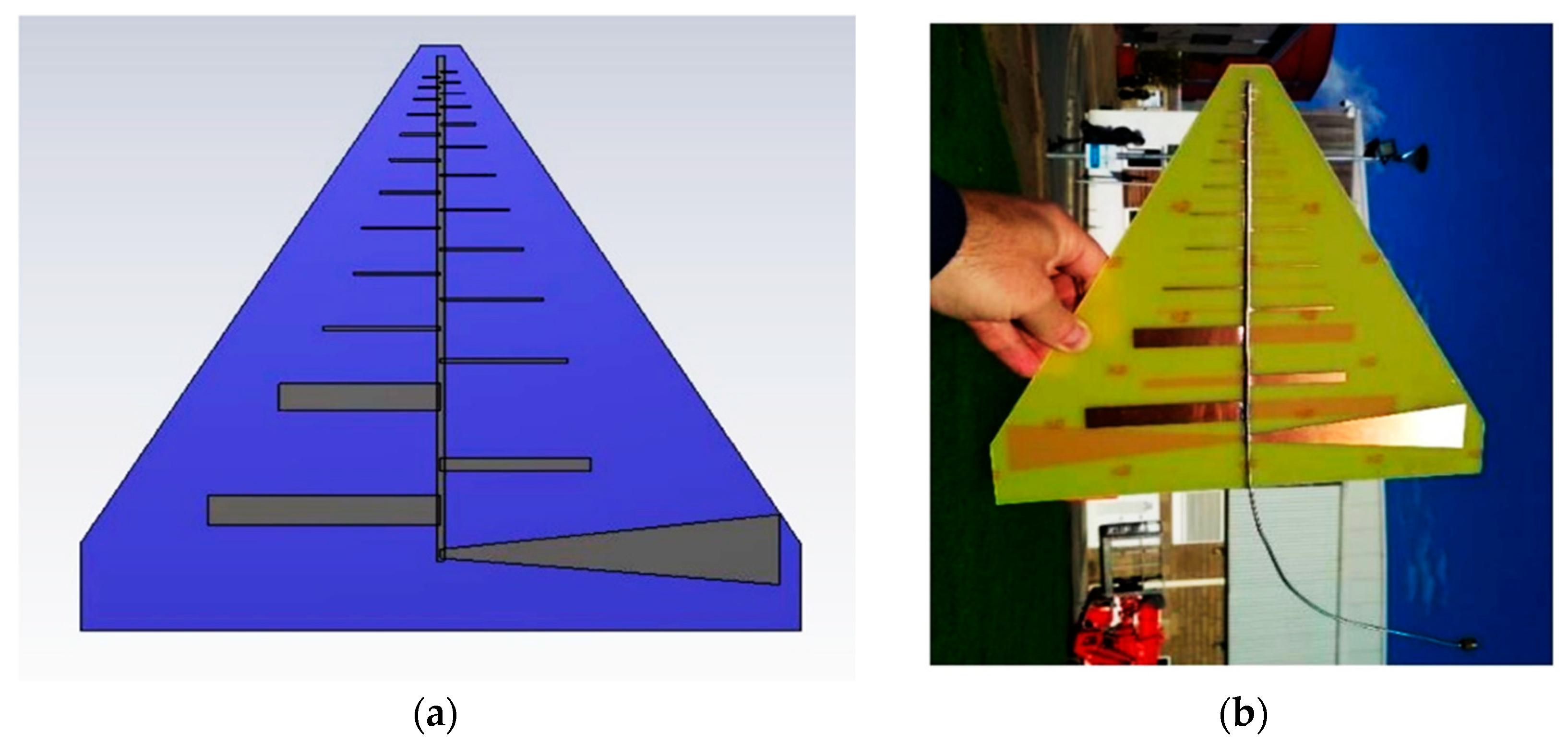
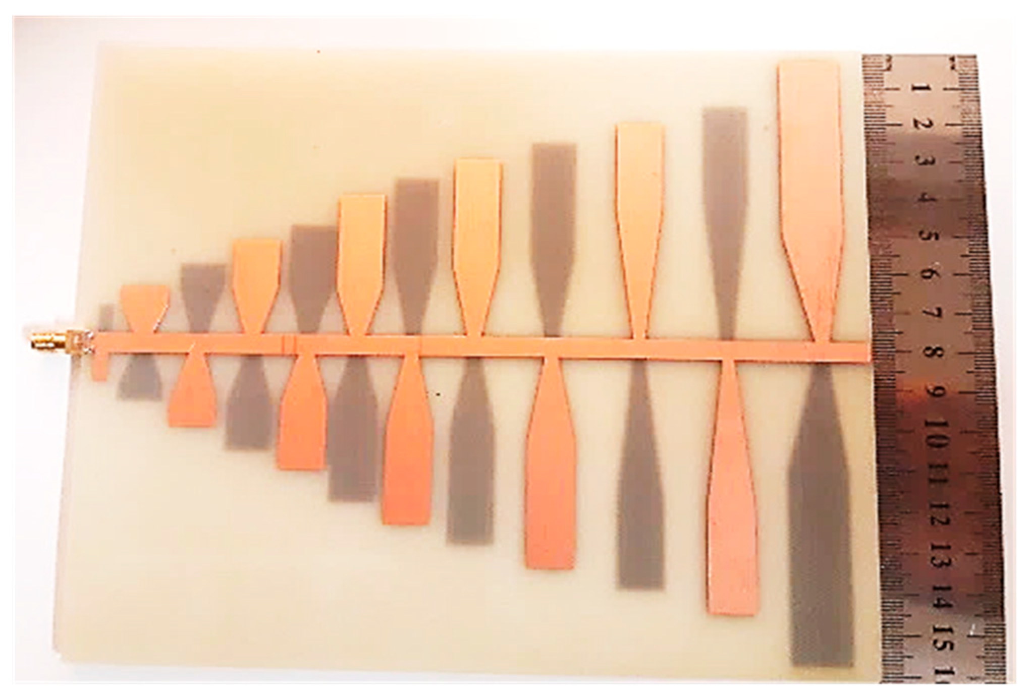
2. Design of PLPDA Antenna

The conventional LPDA was first derived from the traditional dipole in 1958 [24], while an independent frequency antenna was proposed in 1957 [25]. The antenna’s dipoles are arranged in an array style in this design according to each dipole’s wavelength. Three operation regions determine the shape of the radiation in the LPDA antenna. Firstly, the region of the feeding port where the dipoles at this area have a length (L < λ / 2 ), and this region is called the non-active region in which the capacitive effect is dominant. Then, the active region that contains the dipoles in the middle (L = λ / 2 ), where the dipole is starting to radiate, and this region is under the effect of resistance. Finally, the region of dipoles that is far away from the feeding point (L > λ / 2 ), which is called the reflection region. In this region, the inductance effect is dominant. Furthermore, the dipoles in this area reflect the electromagnetic wave and push it back toward smaller length dipoles, making the end-fire radiation pattern [14]. It is worth mentioning that the phase difference between each successive is 180° to ensure the energy will radiate only from the dedicated dipole without any participation from adjacent dipoles.
Designing a traditional LPDA antenna starts by choosing the desired gain or directivity to find out the values of scaling and spacing factors (τ and σ) from the intersection point of the straight line σ = 0.243 τ − 0.051 in the carrel diagram [26]. The number of dipoles can be calculated from Equation (1).
N = 1 + log B S l o g 1 τ
B S = B · B a r = f u p p e r f l o w e r × B a r
B a r = 1.1 + 7.7 ( 1 τ ) 2 4 σ 1 τ
where, B S and B a r present the structure bandwidth and the active region bandwidth, respectively. The length of the most extended dipole (first one), which matches the low frequency, can be found using Equation (4), while the distance between each successive dipole can be calculated using Equation (5).
L 1 = 1 2 × 3 × 10 8 f l o w e r  
R 1 R 2 = L 1 L 2 2 × 4 σ 1 τ  
Equations (6) and (7) are utilized to calculate the length and distance of the successive dipoles.
L n + 1 = τ × L n  
R n + 1 = τ × R n  
The width of the dipole element can be calculated from the following equations:
Z 0 = 377 π ln L n a n 2.25
W n = π × a n
W n + 1 = τ × w n
where Z 0 is the characteristic impedance (50 Ω).
The size limitation issue restricts using LPDA antennas as a reference for EMC measurements, especially at low frequencies starting from 500 MHz or 300 MHz. Therefore, printed log-periodic array antennas were proposed to solve this issue, and these antennas will take into account the effective dielectric constant where the parameters of the conventional LPDA: the length of the dipoles, the width of dipoles, and spacing between dipoles will divide by the square root of the effective dielectric constant, L n ε e f f , W n ε e f f , and R n ε e f f , respectively.
The new design with these updated parameters has a size reduction compared to the conventional structure. Moreover, size reduction and bandwidth enhancement could be achieved by applying different techniques to the PLPDA antenna. Furthermore, the spacing between adjacent dipoles gets smaller as it approaches the high-frequency dipole. Therefore, the spacing should be small to make these sharp bands close to each other, and consequently, it offers a wideband frequency response.
This paper uses the wavelength size and relative bandwidth instead of millimeters and impedance bandwidth. For instance, for a design that operates in the band 800 MHz to 2.5 GHz, the overall size is (160 × 170) mm2. The wavelength of the lower frequency can be calculated as follows:
λ 0 = 3 × 10 8 800 × 10 6 = 375   m m
The   size   in   terms   of   wavelength = S i z e   i n   m m λ 0 = 0.426 × 0.4   λ
The relative bandwidth (RBW) can be calculated from Equation (11)
R B W = f h f l f a v × 100
where,
f a v = f h + f l 2
By substituting the specifications for the example above in Equation (11), we will get R B W = 103 % .
One of the critical parameters in the design of LPDA antennas is the feeding method (type and feed point location) due to its vital role in manipulating the impedance matching, gain, and radiation pattern. In the classical LPDA antennas, the transmission lines are composed of two non-radiated parallel cylindrical bars that connect the successive dipoles at each side. On the other hand, the PLPDA antennas use two non-radiated microstrip lines attached on the top and bottom sides of the substrate. The microstrip line of width w f that reflects input impedance of z 0 =   50 Ω can be estimated from Equation (12), where h is the hight of the substrate while w f stands for the width of the transmission line [27].
z 0 = 87 ε r + 1.41 ln ( 5.98 × h 0.8 × w f )

3. Literature Review of Several PLPDA Antennas for EMC Applications

This section summarizes the latest proposed PLPDA antennas that have been dedicated to working for EMC applications in the last decade.
In 2009 [28], a printed log-periodic dipole array antenna was designed as an EMI sensor. The structure utilizes an FR-4 substrate with a relative permittivity of εr = 4.3 and a loss tangent of tanδ = 0.002. The antenna provides wideband coverage, spanning three significant frequency bands from 625 MHz to 2.6 GHz. The antenna consists of five elements printed on one side and another five on the other side, and each side is connected to the feeding line of width wf = 3 mm and tapered at the end, creating a line width of 20 mm. The reshaping process was applied on the 2nd, 3rd, 4th, and 5th elements to enhance return losses, bandwidth, and gain by adding a triangular shape on the top side of each of the four elements. This structure was designed and optimized using commercial software IE3D (Version 2010). Hence, the optimized size of this design is 0.412 × 0.35 λ, with a relative bandwidth of 125%.
Tapered microstrip lines were applied to each side’s dipole sets for feeding, and these lines have a 20 mm width at the excitation point, as shown in Figure 1.
In 2016 [29], a compact printed log-periodic dipole antenna that operates from 800 MHz to 2.5 GHz was presented. The design process starts with evaluating the antenna parameters in free space conditions, and then modifications were made to take into account the effective dielectric substrate (εeff). This design is based on an epoxy FR-4 substrate with relative permittivity εr = 4.3 and loss tangent tanδ = 0.002. According to the desired gain value of 6.5 dBi, the corresponding scaling and spacing factors were 0.78 and 0.14, respectively. The authors first utilized nine dipoles, but the return losses RL did not satisfy the condition (VSWR < 2). It did not have −10 dB for the whole frequency bands, and there were two frequency bands (RL > −10 dB), one from 1000 MHz to 1050 MHz and another from 1880 MHz to 1985 MHz. Therefore, three extra dipoles were added, and the whole structure was optimized using electromagnetic software to achieve the optimized size. The final design has 12 dipole elements with a size of 0.426 × 0.4 λ and a relative bandwidth of 103%.
A typical microstrip feeding method was used to achieve a characteristic impedance of 50 Ω, and there is a 180° phase shift between the top and bottom array of dipoles, as shown in Figure 2.
In 2016 [30], the authors introduced a balanced feeding technique for a PLPDA antenna designed to operate across a wide frequency range from 500 MHz to 3 GHz, utilizing 12 dipole elements. This approach not only enhances bandwidth but also contributes to size reduction. The performance is benchmarked against the LPDA design in [29], with both antennas featuring the same number of dipoles and using an FR-4 substrate. The balanced feed method addresses the influence of coaxial cable shield soldering, leading to improved radiation performance and a relatively stable gain between 7 and 7.5 dBi. With a scaling factor of 0.86 and a spacing factor of 0.15, the design proves to be a strong candidate for reference antenna applications in EMC measurements. The antenna’s compact form measures 0.443 × 0.25 λ and achieves a relative bandwidth of 143%.
A proposed balance feeding structure was employed in this structure. It modifies the feed lines’ width to balance the current distribution between the top and bottom layers. This method achieves high impedance bandwidth VSWR < 2 from 0.5 GHz to 3 GHz, as shown in Figure 3.
In 2017 [31], The authors presented an optimized compact dipole log-periodic array antenna consisting of 48 elements. Using the built-in optimizer in CST Microwave Studio (version 2015), the antenna’s overall dimensions were fine-tuned to achieve a wideband performance spanning from 0.55 GHz to 9 GHz. The size reduction was accomplished through hat-loading on the first three elements and T-shaped loading on the next three. Additionally, the design incorporates a meandered feedline and trapezoidal stubs to improve impedance matching and broaden the bandwidth, achieving a relative bandwidth of 177%. The antenna is fabricated on a Rogers RO4003 substrate (Rogers Corporation, AZ, USA), characterized by a relative permittivity of εr = 3.55 and a loss tangent of tanδ = 0.0027. The structure uses a scaling factor of 0.93 and a spacing factor of 0.173. While the measured gain varies significantly, ranging from 2.48 to 7.89 dBi, the final compact design has an overall size of 0.49 × 0.355 λ. The geometrical shape is shown in Figure 4. A feedline meander and a trapezoidal stub are attached to the typical transmission lines as impedance matching. These techniques provided good impedance bandwidth for the lower frequency bands.
In 2018 [32], the Trusted Region Framework (TRF) algorithm was used to achieve the optimal parameters of printed log periodic antenna for EMC application. Initially, structure like in [29] was utilized, 12 dipole elements with a scaling factor of 0.86 and spacing factor of 0.14 based on an FR-4 substrate (relative permittivity εr = 4.3 and loss tangent tanδ = 0.002), where the whole parameters in this structure have been optimized. This design has a suitable impedance matching from 800 MHz to 2.5 GHz, with a fluctuated gain of 4.5–6.3 dBi. Using the Trusted Region Framework (TRF) algorithm does not improve bandwidth better than [29]. On the other hand, it provides size reduction as shown in Figure 5. The overall size is 0.426 × 0.373 λ while the relative bandwidth is 103%. The authors applied the Trusted Region Framework (TRF) algorithm on the width of transmission lines. It is found that the best matching is achieved at (Wf = 1 mm).
In 2018 [33], the shortened log-periodic dipole array antenna was achieved using printed dual-band dipole elements instead of the classical dipole. Since each dipole resonates at its frequency band, these dipoles are optimized in a manner where its frequency band overlapping leads to wideband behavior (0.5–10 GHz). This technique achieves bandwidth enhancement (relative bandwidth 181%) and a size reduction of 19%. The number of dipoles used is 25 compared to 40 elements for the conventional dipole. Furthermore, Rogers RO4003 substrate with relative permittivity εr = 3.55 and loss tangent tanδ = 0.0027 is used as a substrate with a scaling factor of 0.916 and a spacing factor of 0.16. The overall size is 0.36 × 0.43 λ, and the realized gain has a fluctuation of 3–6 dBi. The geometrical shape is shown in Figure 6. Two microstrip transmission lines with a characteristic impedance of 50 Ω are attached to the substrate’s top and bottom to connect the successive dual-band dipole elements.
In 2020, [34] a printed log-periodic dipole array antenna with a wide bandwidth ranging from 0.7 to 8 GHz was developed. The enhanced bandwidth was achieved by modifying the shape of the longest dipole from a rectangular to a triangular form and optimizing the lengths of the last four dipole elements. Designed as a reference antenna for EMC measurements, it offers a wide relative bandwidth of 180% and a compact size. However, the antenna does not maintain a return loss below −10 dB across the entire frequency range. Specifically, three frequency bands exhibit return losses above −10 dB: 0.6–0.8 GHz, 1.0–1.2 GHz, and 1.5–1.7 GHz. The authors suggested that further enhancement in return loss performance could be achieved across the full band by replacing the 22nd, 23rd, and 24th dipole elements with triangular-shaped ones. This antenna consists of 25 dipole elements fabricated on an FR-4 substrate with a scaling factor of 0.9 and a spacing factor of 0.16. The realized gain had many fluctuations with an average value of 5.5 dBi, and the overall size is 0.36 × 0.37 λ. The geometrical shape is shown in Figure 7. Moreover, the width of the top and bottom transmission lines are optimized using the Trusted Region Framework (TRF) algorithm, exactly like in [30].
In 2022 [35], a printed log-periodic biconical dipole array (PLPBDA) antenna was presented. Regarding the dipole characteristics and the fact that the thicker dipole had a wider bandwidth, authors replaced the standard dipoles with trapezoidal ones to form a biconical or bow-tie shape and to achieve a wide bandwidth from 0.5 to 6.5 GHz. The design started with eleven biconical dipoles based on an FR-4 substrate with a scaling factor of 0.86 and a spacing factor of 0.16. Then an extra traditional dipole was added to enhance the reflection coefficient and provide a low infatuation gain 4.6–7 dBi. Furthermore, both lateral and boom sizes have been minimized and reflect the size of (0.28 × 0.26 λ) with a relative bandwidth of 170%. Furthermore, a balanced feeding line method was involved in providing impedance matching. The top microstrip line has a width wf1 = 3.5 mm while the width of the bottom microstrip line is wf2 = 5 mm as shown in Figure 8.

4. Specifications of Antenna Design for EMC Applications

4.1. Size Reduction (SR%)

Compact size is one of the benefits of using PCB technology where the whole dimensions of the classical antenna will divide by the square root of the relative permittivity. This feature is helpful to overcome two issues in the electromagnetic compatibility test inside the EMC chamber as follows.

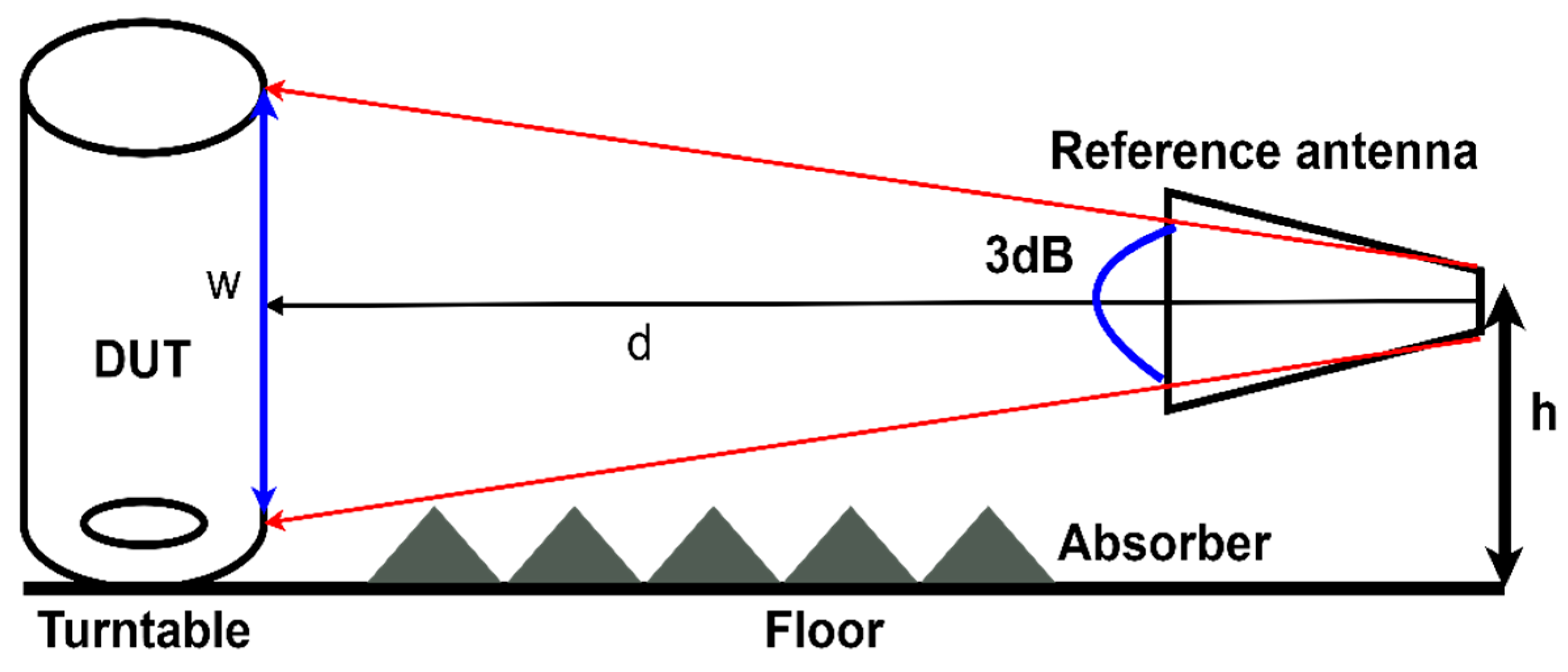
4.1.1. Test Configuration Issue

Based on EMC standard (CISPR 16-2-3), the minimum distance between the reference antenna and the ground plane must not exceed 25 cm. The main problem will occur through the test with the vertical orientation of the antenna, where the antenna will be close to the ground, especially at low frequencies. This problem will lead to wrong measurements due to the interference between the antenna and the ground plane. This problem will not be an issue in the printed reference antennas due to the small size they have (uses substrate with relative permittivity εr = 4.3 to minimize the size). So, it satisfies the condition even with low frequencies.

4.1.2. Short Measurement Distance

During the immunity test, we need a constant level of interference power at the Uniform Field Area (UFA) to measure the robustness of the device under the test with such a power. The problem is that the device under the test maybe has different dimensions, and this uniform field will not be able to cover all sides. Several solutions could address to get the maximum field strength at the UFA to overcome this issue [36]. For instance:
  • Using a power amplifier to increase the power level at the UFA.
  • Using another antenna to get the maximum field strength. This option is not recommended because having many antennae inside the EMC chamber will affect the measurement results.
  • Shorting the measurement distance (the distance between the reference antenna and the device under the test), the problem is that the immunity test should be performed in the far field and shortening this distance will make the measurement in the near field, and the measurement results will not be valid. The biggest dimension of the antenna determines the starting point of the far-field area. However, the reference antenna with a compact size has a starting point of the far-field area closer to the compact antenna than the classical antenna. This antenna gives the flexibility of shortening the measurement distance to achieve the required field strength and guarantees the measurements will be performed in the far-field area.
Unfortunately, most of the reviewed articles did not reveal the size reduction percentage. Therefore, the equivalent conventional size has been calculated by implementing the specifications of each reviewed paper (substrate type, relative permittivity, height, spacing parameter, scaling parameter, lower frequency, and higher frequency) in Matlab. Hence the size reduction has been calculated using the following relation. Table 1 illustrates the proposed articles’ lateral and boom size reduction compared with the equivalent conventional size with the exact specifications.
S i z e   r e d u c t i o n = l e n g t h   o f   t h e   c o n v e n t i o n a l   P L P D A l e n g t h   o f   t h e   p r o p o s e d   P L P D A l e n g t h   o f   t h e   c o n v e n t i o n a l   P L P D A × 100 %

4.2. Bandwidth Enhancement

The tuned dipoles were the best choice to overcome the bandwidth limitation of dipoles for EMC measurements. At the same time, it showed low efficiency as it is time-consuming to cover the whole frequency range and set the configuration at every tuning process. Therefore, other types of antenna have been proposed to mitigate these issues, like biconical antenna [10], log-periodic dipole array antenna [12], and horn antenna [15]. The classical biconical antenna is dedicated to serving in the band from 20 MHz and 300 MHz, while it is still electrically large (1.37 m wide), especially for low frequencies, and based on the test configuration issue that has been addressed in size reduction section, the VSWR would be higher and inefficient. Furthermore, the log-periodic dipole array antenna is dominant in the band, starting from 300 MHz to 1 GHz, and some structures reach up to 6 GHz.
The typical industry frequency range is 30 MHz up to 6 GHz and could be wider. Moreover, this band is considered a very critical band since it is exploited with different applications that have a high probability of interference like GSM 850–900 MHz, mobile 1800 MHz, 3G 2100 MHz, Wi-fi 2400 MHz, Wi-MAX 3.5 GHz, and 5.3 GHz, PAN 4.8 GHz, and WLAN 5.8 GHz. The PLPDA antenna uses the benefits of printed circuit technology like the low profile printed circuit board and the possibility of applying different bandwidth enhancement techniques. Table 2 shows the design specifications for the reviewed papers.

4.3. Antenna Factor (AF)

The antenna factor is a key parameter in the design of electromagnetic sensors, indicating the suitability of an antenna for use as a reference. It defines the ratio between the electric field strength at the antenna’s surface and the voltage induced at its terminals. Additionally, this factor plays a vital role in EMC measurements as it directly influences the measurement accuracy and minimizes uncertainty [37,38].
The noise measurement will be more significant in the high frequencies, and the antenna should have an appropriate, smooth, and balanced antenna factor. Therefore, enhancing the antenna factor requires only improving the gain of the printed antenna with different methods since the realized gain and the antenna factor are related to each other using the following Equation (13) [39].
A F = 20 log 2 π λ   2.4 10 ( G ( d B i ) / 10 )
where λ is the wavelength, and G is the gain of the antenna in dBi.
The achieved antenna factor of the proposed antenna could be compared numerically with the antenna factor of an equivalent classical design that has the same frequency coverage. Unfortunately, this factor is missing in the reviewed articles except for references [28,35]. The antenna factor of the rest of the articles has been calculated from the presented realized gain in dBi according to Equation (13). Moreover, Figure 9 depicts the antenna factor of the literature reviewed compared with the AF of the commercial design HyperLOG® 7060 from the AARONIA AG website (Strickscheid, Germany) [40]. It can be seen that the AF of the proposed structures coincides with the classical antenna factor. For more details, the numerical values of the antenna factor for the reviewed papers are listed in Table 3.
The numerical value of the antenna factor of the proposed structures has been compared with that of the classical commercial design (HyperLOG 7060), as shown in Table 3. The commercial antenna has been considered a reference for comparison since it has the same frequency range and is calibrated according to the CISPR standards. AF of [35] has better performance than other references because it has lower values of the antenna factor with a maximum difference of 1.5 dBm−1 compared to the classical design.

4.4. The Half Power Beamwidth Angle (θ3dB)

The setup of the EMC measurement in both the radiation and susceptibility tests will be valid by covering the device under the test by the far-field radiation of the reference antenna in both horizontal and vertical directions. The horizontal direction is obtained with the turntable under the device under the test, while moving the reference antenna vertically from 1 m to 4 m height which will cover the vertical direction of the DUT. Furthermore, the minimum dimension of a vertical line tangent to the DUT w can be calculated from the beamwidth angle of the reference antenna θ3dB using Equation (14) (Figure 10) [41].
w = 2 × d × t a n   ( 0.5 × θ 3 d B )
The beamwidth angle (θ3dB) and the tangent line distance w for the proposed reviewed literature should be compared with the standard results of the LPDA antenna presented in [41]. Unfortunately, most of the reviewed papers do not have information on the beamwidth angles; the beamwidth angle has been extracted from the radiation pattern for some articles like [31,33]. The beamwidth angle and tangent line distance w for the proposed papers compared with the CISPR standard are listed in Table 4.

5. Discussion and Recommendations

Eight articles related to the PLPDA antenna design for EMC applications have been presented. Furthermore, the specifications of each design are discussed in detail. Some of these structures are intended to have a wide bandwidth using the bandwidth enhancement method. In contrast, the others are focused on size reduction to achieve a compact size suitable for a small relativity chamber. Design recommendations of the PLPDA antenna for EMC measurement are presented as follows:
  • The wide bandwidth: the proposed PLPDA antenna must have a wide bandwidth where Fmax/Fmin > 10 so that the impedance and radiation characteristics remain constant as a frequency function, which is why it is called a frequency-independent antenna [42].
  • The majority of EMC antennas are designed to operate within the 0.7 GHz to 2.4 GHz frequency range, as it encompasses several widely used applications such as GSM (850–900 MHz), mobile networks (1800 MHz), 3G (2100 MHz), and Wi-Fi (2400 MHz), making it highly susceptible to interference. Furthermore, increasing the bandwidth to 6 GHz is essential to catch the interference emitted from Wi-MAX 3.5 GHz and 5.3 GHz, PAN 4.8 GHz, and WLAN 5.8 GHz applications [43].
  • The compact size of the printed antenna will achieve the maximum field strength at the UFA during the immunity test and will satisfy the test configuration issue.
  • The antenna should have a steady phase center where the polarization of the radiation pattern will stay constant with the frequency [44].
  • The axial ratio (AR) is an essential factor in identifying the antenna’s polarization type, linear, elliptical, or circular polarization. The reference antenna is required to be linearly polarized according to the EMC community [45]. The range from 0 to 3 dB value of AR is dedicated to the circular polarization. The elliptical polarization starts from AR with 3 dB up to infinity, and the infinity value of AR stands for the linear polarization. Currently, no practical or industrial standard exists to distinguish elliptically polarized antennas from linearly polarized ones based solely on axial ratio. As a result, linear polarization can be considered a special case of elliptical polarization [46].
  • Unfortunately, a slight deviation in the polarization will occur from the intended design for one reason or another. For instance, even the log-periodic dipole array antenna with a unique distribution of linear dipoles exhibits elliptical polarization instead of linear polarization [47].
  • The co-and cross polarization of radiation pattern for both E and H field are necessary aspects and the acceptable level of cross polarization according to EMC standards lies between −14 dB to −20 dB [45].
  • The reference antenna for measurement has a high directive characteristic: The flat gain is preferable to a fluctuation gain since it distributes the electromagnetic waves inside the chamber. Moreover, the flat realized gain reflects smooth balance and constant antenna factor.
  • The uncertainty of the reference antenna can be determined by finding out the measured error from comparison the measured radiation incident field of the proposed antenna with that of commercial design in a process called calibration. Moreover, this maximum difference should compare with the acceptable level of EMC standard [48,49].
  • Future work on this topic could be included:
    • Proposing new techniques for size reduction and bandwidth enhancement at the same time as [50,51]
    • Enhancing the radiation characteristics like radiation pattern, gain and directivity, especially at high frequencies, using radiation pattern enhancement techniques like metalenses [52].
    • Propose a compact antenna for both radiation emission and immunity tests with the help LPDA antenna as [53].

Author Contributions

Conceptualization, A.A.A. and Z.K.; methodology, A.A.A.; investigation, A.A.A. and Z.K.; resources, A.A.A. and Z.K.; writing—review and editing, A.A.A. and Z.K. All authors have read and agreed to the published version of the manuscript.

Funding

This work was funded by the SGS-2024-005 project, focused on contemporary approaches to the development, design, and implementation of electronic and communication systems.

Data Availability Statement

Data are contained within the article.

Acknowledgments

The authors would like to show their gratitude to the University of West Bohemia and Southern Technical University for their support throughout performing the study.

Conflicts of Interest

The authors declare no conflicts of interest.

References

  1. Abdulhameed, A.A.; Alhamdawee, E.M.; Hayder, I.M. Review of reconfigurable/UWB antenna for interweave cognitive radio applications. Aust. J. Electr. Electron. Eng. 2019, 16, 96–101. [Google Scholar] [CrossRef]
  2. Abdulhameed, A.A.; Kubik, Z. Investigation of Broadband Printed Biconical Antenna with Tapered Balun for EMC Measurements. Energies 2021, 14, 4013. [Google Scholar] [CrossRef]
  3. Alnahwi, F.M.; Abdulhameed, A.; Abdullah, A.S. A Compact Integrated UWB/Reconfigurable Microstrip Antenna for Interweave Cognitive Radio Applications. Int. J. Commun. Antenna Propag. (IRECAP) 2018, 8, 13078. [Google Scholar] [CrossRef]
  4. Alnahwi, F.M.; Abdalhameed, A.A.; Swadi, H.L.; Abdullah, A.S. A compact wide-slot UWB antenna with reconfigurable and sharp dual-band notches for underlay cognitive radio applications. Turk. J. Electr. Eng. Comput. Sci. 2019, 27, 94–105. [Google Scholar] [CrossRef]
  5. Mohammed, A.A.; Alnahwi, F.M.; Abdullah, A.S.; Hameed, A.G.A.A. A Compact Monopole Antenna with Reconfigurable Band Notch for Underlay Cognitive Radio Applications. In Proceedings of the 2018 International Conference on Advance in Sustainable Engineering and Its Application (Icasea), Wasit-Kut, Iraq, 14–15 March 2018; pp. 25–30. [Google Scholar]
  6. Group, M.V. Considerations in Emi Antenna Design. Available online: http://www.interferencetechnology.com/wp-content/uploads/2021/02/Whitepaper-EMC-Considerations-in-EMI-Antenna-Design.pdf (accessed on 10 January 2023).
  7. Maddocks, A. 23—Electromagnetic Compatibility. In Electrical Engineer’s Reference Book, 16th ed.; Laughton, M.A., Warne, D.J., Eds.; Newnes: Oxford, UK, 2003; pp. 16–23. [Google Scholar]
  8. Gifuni, A.; Bastianelli, L.; Gradoni, G.; Moglie, F.; Perna, S.; Smartt, C.; Primiani, V.M. On the Shielding Effectiveness Calculation of Enclosures Through Measurements in Reverberation Chambers. IEEE Trans. Electromagn. Compat. 2021, 63, 1395–1406. [Google Scholar] [CrossRef]
  9. Kubik, Z.; Skala, J. Shielding Effectiveness Simulation of Small Perforated Shielding Enclosures Using FEM. Energies 2016, 9, 129. [Google Scholar] [CrossRef]
  10. Lin, F.; Qi, Y.; Fan, J.; Jiao, Y.-C. 0.7–20-GHz Dual-Polarized Bilateral Tapered Slot Antenna for EMC Measurements. IEEE Trans. Electromagn. Compat. 2014, 56, 1271–1275. [Google Scholar] [CrossRef]
  11. Sapuan, S.Z.; Kazemipour, A.; Mohd Jenu, M.Z. Direct feed biconical antenna as a reference antenna. In Proceedings of the 2011 IEEE International RF & Microwave Conference, Seremban, Malaysia, 12–14 December 2011; pp. 5–8. [Google Scholar]
  12. Velicheti, S.; Mallikarjuna Rao, P. An Analytical Review on Log Periodic Dipole Antennas with Different Shapes of Dipole Elements. In Microelectronics, Electromagnetics and Telecommunications; Lecture Notes in Electrical Engineering; Springer: Singapore, 2021; pp. 621–631. [Google Scholar]
  13. Bang, J.; Han, C.; Jung, K.; Choi, J. High-Frequency Performance Improvement of LPDA for EMC/EMI Measurements. In Proceedings of the 2020 International Symposium on Antennas and Propagation (Isap), Osaka, Japan, 25–28 January 2021; pp. 621–622. [Google Scholar]
  14. Ivsic, B.; Friscic, F.; Dadic, M.; Muha, D. Design and Analysis of Vivaldi Antenna for Measuring Electromagnetic Compatibility. In Proceedings of the 2019 42nd International Convention on Information and Communication Technology, Electronics and Microelectronics (MIPRO), Opatija, Croatia, 20–24 May 2019; pp. 491–495. [Google Scholar]
  15. Jiang, J.; Pan, S.; Wang, S.; Li, G. Miniaturization Design of VHF Broadband Directional Radiation TEM Horn Antenna. In Proceedings of the 2020 International Conference on Microwave and Millimeter Wave Technology (ICMMT), Shanghai, China, 20–23 September 2020; pp. 1–3. [Google Scholar]
  16. Gerber, M.; Odendaal, J.W.; Joubert, J. DRGH Antenna With Improved Gain and Beamwidth Performance. Propagation 2019, 68, 4060–4065. [Google Scholar] [CrossRef]
  17. Mallahzadeh, A.R.; Pazoki, R.; Karimkashi, S. A new UWB skeletal antenna for EMC applications. In Proceedings of the IEEE 2007 International Symposium on Microwave, Antenna, Propagation and Emc Technologies for Wireless Communications, Vols I and Ii, Hangzhou, China, 16–17 August 2007; p. 543. [Google Scholar]
  18. Kim, K.C.; Choi, B.J.; Jung, S.W. Characteristics of the Sleeve Dipole Antenna Used for EMC Applications. IEEE Access 2020, 8, 86957–86961. [Google Scholar] [CrossRef]
  19. Hacene, Y.; Xie, S.G. Study of a Novel Ultra-Wideband Monopole Antenna for EMC Measurement Applications. In Proceedings of the 2012 6th Asia-Pacific Conference on Environmental Electromagnetics (Ceem’ 2012), Shanghai, China, 6–9 November 2012; pp. 393–395. [Google Scholar]
  20. Kuhn, W.; Peterson, G.; Welch, J. Broadband Antenna Probe for Microwave EMC Measurements. In Proceedings of the 2018 IEEE 27th Conference on Electrical Performance of Electronic Packaging and Systems (EPEPS), San Jose, CA, USA, 14–17 October 2018; pp. 199–201. [Google Scholar]
  21. Song, Q.; Shen, Z.; Lu, J. Log-Periodic Monopole Array With Uniform Spacing and Uniform Height. IEEE Trans. Antennas Propag. 2018, 66, 4687–4694. [Google Scholar] [CrossRef]
  22. Hu, Z.; Shen, Z.; Wu, W.; Lu, J. Low-Profile Log-Periodic Monopole Array. IEEE Trans. Antennas Propag. 2015, 63, 5484–5491. [Google Scholar] [CrossRef]
  23. Abdulhameed, A.A. Circular slotted monopole printed antenna with grounded stub WLAN band-notch for UWB applications. Aust. J. Electr. Electron. Eng. 2018, 14, 59–63. [Google Scholar] [CrossRef]
  24. DuHamel, R.; Isbell, D. Broadband logarithmically periodic antenna structures. In Proceedings of the 1958 IRE International Convention Record, New York, NY, USA, 21–25 March 1966; pp. 119–128. [Google Scholar]
  25. Rumsey, V.H. Frequency Independent Antennas. In Proceedings of the 1958 IRE International Convention Record, New York, NY, USA, 21–25 March 1966; Volume 45, p. 385. [Google Scholar]
  26. Carrel, R. The design of log-periodic dipole antennas. In Proceedings of the IRE International Convention Record, New York, NY, USA, 21–25 March 1966; pp. 61–75. [Google Scholar]
  27. Balanis, C.A. Antenna Theory: Analysis and Design; John Wiley & Sons: Hoboken, NJ, USA, 2015. [Google Scholar]
  28. Gupta, N.; Haque, A. Design of printed log periodic EMI sensor. Int. J. Microw. Opt. Technol. 2009, 4, 211–215. [Google Scholar]
  29. Limpiti, T.; Chantaveerod, A.Y. Design of a printed log-periodic dipole antenna (LPDA) for 0.8–2.5 GHz band applications. In Proceedings of the 2016 13th International Conference on Electrical Engineering/Electronics, Computer, Telecommunications and Information Technology (ECTI-CON), Chiang Mai, Thailand, 28 June 2016–1 July 2016; pp. 1–4. [Google Scholar]
  30. Yu, L.B.; Chai, S.L.; Huang, H.; Ding, L.; Xiao, K.; Zhao, F. A Printed Log-periodic Dipole Antenna with Balanced Feed Structure. In Proceedings of the 2016 Progress in Electromagnetics Research Symposium (Piers), Shanghai, China, 8–11 August 2016; pp. 2035–2038. [Google Scholar]
  31. Kyei, A.; Sim, D.U.; Jung, Y.B. Compact log-periodic dipole array antenna with bandwidth-enhancement techniques for the low frequency band. Iet Microw. Antennas Propag. 2017, 11, 711–717. [Google Scholar] [CrossRef]
  32. Mistry, K.K.; Lazaridis, P.I.; Zaharis, Z.D.; Xenos, T.D.; Tziris, E.N.; Glover, I.A. An optimal design of printed log-periodic antenna for L-band EMC applications. In Proceedings of the 2018 Joint Ieee International Symposium on Electromagnetic Compatibility and 2018 Ieee Asia-Pacific Symposium on Electromagnetic Compatibility (Emc/Apemc), Singapore, 14–18 May 2018; pp. 1150–1155. [Google Scholar]
  33. Anim, K.; Jung, Y.B. Shortened Log-Periodic Dipole Antenna Using Printed Dual-Band Dipole Elements. IEEE Trans. Antennas Propag. 2018, 66, 6762–6771. [Google Scholar] [CrossRef]
  34. Mistry, K.K.; Lazaridis, P.I.; Zaharis, Z.D.; Loh, T.H. Design and Optimization of Compact Printed Log-Periodic Dipole Array Antennas with Extended Low-Frequency Response. Electronics 2021, 10, 2044. [Google Scholar] [CrossRef]
  35. Abdulhameed, A.A.; Kubík, Z. Design a Compact Printed Log-Periodic Biconical Dipole Array Antenna for EMC Measurements. Electronics 2022, 11, 2877. [Google Scholar] [CrossRef]
  36. Wu, Q.; Ding, X.; Su, D. A Compact Dipole Antenna With Curved Reflector for 1.0–4.2 GHz EMC Measurement. IEEE Trans. Electromagn. Compat. 2015, 57, 1289–1297. [Google Scholar] [CrossRef]
  37. Sapuan, S.Z.; Herie, F.H.; Jenu, M.Z.M. A New Small Sized Wideband Biconical Antenna For Electromagnetic Compatibility (EMC) Measurements. In Proceedings of the 2016 IEEE Asia-Pacific Conference on Applied Electromagnetics (Apace), Langkawi, Malaysia, 11–13 December 2016. [Google Scholar]
  38. Sapuan, S.Z.; Jenu, M.Z.M.; Kazemipour, A. Calibration of Calculable Wideband Direct Feed Biconical Antenna for EMC Measurements. In Proceedings of the 2013 Asia-Pacific Symposium on Electromagnetic Compatibility (Apemc), Melbourne, VIC, Australia, 20–23 May 2013. [Google Scholar]
  39. McLean, J.; Sutton, R.; Hoffman, R. Interpreting antenna performance parameters for EMC applications: Part 3: Antenna Factor. TDK RF Solut. 2004, 18–26. Available online: https://www.tdkrfsolutions.tdk.com/images/uploads/brochures/antenna_paper_part3.pdf (accessed on 10 January 2023).
  40. Shop, A. HyperLOG® 7060. Available online: https://aaronia.com/en/breitband-antenne-hyperlog7060?srsltid=AfmBOoo_ZMu0VXkpOWGytpv2WWLrRQ8nOa3Ee-hsR3HcGVsc1d604d9p (accessed on 10 January 2023).
  41. CISPR16-1-2; Specification for Radio Disturbance and Immunity Measuring Apparatus and Methods-Part 1-2: Radio Disturbance and Immunity Measuring Apparatus-Ancillary Equipment-Conducted Disturbances. ASEAN Trade Repository: Hanoi, Vietnam, 2006.
  42. Koldaş, M. Ultra Wideband Tightly Coupled Reflectarray Antenna. Master’s Thesis, Middle East Technical University, Çankaya/Ankara, Türkiye, 2022. [Google Scholar]
  43. Sah, S.; Verma, D. 5G Communication Challenges and Opportunities. In Multifunctional MIMO Antennas: Fundamentals and Application; CRC Press: Boca Raton, FL, USA, 2022. [Google Scholar]
  44. Stutzman, W.L.; Thiele, G.A. Antenna Theory and Design; John Wiley & Sons: Hoboken, NJ, USA, 2012. [Google Scholar]
  45. Alexander, M.; Salter, M.; Gentle, D.; Knight, D.; Loader, B.; Holland, K. Calibration and Use of Antennas, Focusing on EMC Applications; NPL: London, UK, 2004. [Google Scholar]
  46. Patre, S.R.; Singh, S.; Singh, S. Effect of dielectric substrate on performance of planar trapezoidal toothed log-periodic antenna. In Proceedings of the 2013 Students Conference on Engineering and Systems (SCES), Allahabad, India, 12–14 April 2013; pp. 1–4. [Google Scholar]
  47. McLean, J.; Sutton, R.; Hoffman, R. Interpreting Antenna Performance Parameters for EMC Applications: Part 1: Radiation Pattern, ain, and Directivity; TDK RF Solutions: Cedar Park, TX, USA, 2004. [Google Scholar]
  48. Ghosh, S.; Srivastava, A.K.; Sarkar, B.K. Measurement of radiated emission using different EMI sensors in the laboratory environment. In Proceedings of the International Conference on Electromagnetic Interference & Compatibility, Pittsburgh, PA, USA, 6–10 August 2012; pp. 217–221. [Google Scholar]
  49. Stecher, M. Uncertainty in RF Emission Measurements: Revision of CISPR 16-4-2. 2009. Available online: https://emc-chap-it.polimi.it/download/MUinEMC_Revision%20of%20CISPR%2016-4-2%20doc.pdf (accessed on 10 January 2023).
  50. Parizi, S.A.R. Bandwidth Enhancement Techniques. In Trends in Research on Microstrip Antennas; Sudipta Chattopadhyay; IntechOpen: Rijeka, Croatia, 2017. [Google Scholar]
  51. Herath, H.M.S.M.; Jayasinghe, J.M.J.W.; Uduwawala, D.N. Performance Improvement of Printed Log Periodic Dipole Array Antennas. In Proceedings of the 2021 IEEE 16th International Conference on Industrial and Information Systems (ICIIS), Kandy, Sri Lanka, 9–11 December 2021; pp. 52–57. [Google Scholar]
  52. Guo, L.; Wang, Z.; Zeng, W.; Hou, S.; Yang, Z.; Liu, Y. A compact and high gain metalens antenna based on impedance matching mechanism. AEU—Int. J. Electron. Commun. 2022, 146, 154113. [Google Scholar] [CrossRef]
  53. Abdulhameed, A.A.; Kubík, Z. Using of LPDA Antenna for UFA Evaluation in Radiated Immunity Test. In Proceedings of the 2023 International Conference on Applied Electronics (AE), Pilsen, Czech Republic, 6–7 September 2023; pp. 1–4. [Google Scholar]
Figure 1. Proposed log-periodic dipole EMI Sensor in [28].
Inventions 10 00034 g001
Figure 2. The photograph of the fabricated shape of the proposed structure in [29].
Inventions 10 00034 g002
Figure 3. Traditional feeding structures for PLPDA antenna in [30].
Inventions 10 00034 g003
Figure 4. Photograph of the fabricated planar LPDA antenna in [31].
Inventions 10 00034 g004
Figure 5. Optimized PLPDA structure based on FR4 substrate in [32].
Inventions 10 00034 g005
Figure 6. Photograph of the fabricated LPDA antenna with dual-band dipole elements in [33].
Inventions 10 00034 g006
Figure 7. (a) A CST model of the proposed PLPDA antenna in [34]; (b) the fabricated shape of the proposed structure [34].
Inventions 10 00034 g007
Figure 8. Fabricated shape of the proposed antenna in [35].
Inventions 10 00034 g008
Figure 9. The antenna factor extracted from gain for the eight configurations and the commercial design, AF HyperLOG 7060 [40], AF “Gupta, 2009” [28], AF “Limpiti, 2016” [29], AF “Kyei, 2017” [31], AF “Mistry, 2018” [32], AF “Anim, 2018” [33], AF “Mistry, 2021” [34], AF “Abdulhameed, 2022” [35].
Inventions 10 00034 g009
Figure 10. The EMC measurements chamber according to the CISPR standard [33].
Inventions 10 00034 g010
Table 1. Lists the size reduction percentage for the reviewed papers.
Ref.Size of the Proposed PLPDASize of the Conventional PLPDASR% BoomSR % Lateral
[28]206 × 185 × 1.6278 × 251 × 1.62526
[29]160 × 150 × 1.6230 × 164 × 1.6308.5
[31]268 × 194 × 1335 × 265 × 12027
[32]150 × 160 × 1222 × 198 × 13219
[33]218 × 260 × 1364 × 310 × 14016
[34]270 × 279 × 1380 × 300 × 1297
[35]170 × 160 × 1.6340 × 320 × 1.65050
Table 2. List the most critical specifications in the PLPDA antenna of the reviewed eight articles.
Ref.F/GHzFBW ε r τ Gain/dBiNSize/λFeeding MethodApplication
[28]0.6–2.6125%4.3---*114 dB50.41 × 0.35taperedEMC
[29]0.8–2.5103%4.30.786.5120.42 × 0.4TypicalEMC
[30]0.5–3143%4.30.867–7.5120.25 × 0.44BalancedEMC
[31]0.55–9177%3.50.932.4–7.8480.49 × 0.35TypicalEMC
[32]0.8–2.396.7%4.30.864.5–6.3120.42 × 0.37OptimizedEMC
[33]0.5–10181%3.50.913–6250.36 × 0.43TypicalEMC
[34]0.7–8180%4.30.95.5250.36 × 0.37typicalEMC
[35]0.5–6170%4.30.864.6–7120.28 × 0.26typicalEMC
---*1 there is no information from the reference.
Table 3. List the numerical values of AF in the PLPDA antenna of the reviewed eight articles.
Freq.AF [28]AF [29]AF [32]AF [31]AF [33]AF [34]AF [35]AF [HyperLOG 7060] [40]
0.5---------20202218.1---
12625252325.529.524.526
1.529.52828.52728.53028.129
231.93031.53031.530.531.531.5
2.53431.532.53233.53232.933
3---------34363434.335
3.5---------3537.53535.136.5
4---------363936.536.237.25
4.5---------37403737.7837.75
5---------37.9413839.538.5
5.5---------3941.538.539.5440.5
6---------40424041.1842
--- there is no information from the reference.
Table 4. Lists the numerical values of beamwidth angle and tangent line distance for different PLPDA antenna structures compared with CISPR standard.
Freq./GHzθ3dBW/mθ3dBW/mθ3dBW/mθ3dBW/mθ3dBW/m
Ref.[31][31][33][33][34][34][35][35]CISPRCISPR
1721.45480.89721.451122.95601.15
2---*1---*1---*1---*1841.81414.28551.04
4721.45651.27831.76551.04551.04
6---*1---*1---*1---*1661.346.40.85551.04
---*1 there is no information from the reference.
Disclaimer/Publisher’s Note: The statements, opinions and data contained in all publications are solely those of the individual author(s) and contributor(s) and not of MDPI and/or the editor(s). MDPI and/or the editor(s) disclaim responsibility for any injury to people or property resulting from any ideas, methods, instructions or products referred to in the content.

