1. Introduction
The aim of the LHCb experiment in its Upgrade-2 incarnation [
1,
2] is to pursue extreme-precision measurements in quark-flavour physics during LHC operation beyond 2030 [
3]. The detector will collect a total integrated luminosity of 300 fb
of
collisions during Runs 5 and 6 and will operate at a maximum instantaneous luminosity of
cm
s
, i.e. about a factor of 10 larger than that of the LHCb Upgrade-1 [
4]. The much higher radiation dose and increased particle flux will require substantial modifications of all LHCb subdetectors. A promising strategy to cope with the much-increased pile-up conditions exploits the fact that primary
collisions in an LHC bunch crossing are spread in time with a root mean square (RMS) of approximately 200 ps. Measuring the time of subdetector hits will allow them to be associated with the corresponding primary vertex, as well as the ghost rate to be reduced. In particular, according to simulations, the electromagnetic calorimeter (ECAL) will have to measure the arrival time of electrons, positrons and photons in the 5–100 GeV range with resolutions of 10–20 picoseconds [
2]. To achieve this level of precision, the implementation of a dedicated timing layer based on microchannel plates (MCPs) is being investigated.
The timing layer will be placed between two sections of a longitudinally segmented ECAL, with the aim of sampling the charged component of electromagnetic showers. The idea of using MCP-based devices in calorimetry dates to the 1990s [
5] but has never been applied in a real case. Photomultipliers based on MCPs (MCP-PMTs) have excellent spatial and time resolutions, and are very promising for the purpose of building a timing-layer detector. For example, using a Cherenkov radiator in front of an MCP-PMT, the authors of Ref. [
6] measured the arrival time of a single particle with a resolution of about 5 ps. However, MCP-PMTs suffer from well-known limitations due to lifetime, deadtime and cost that prevented their application in large-area detectors working in high-rate environments so far.
New opportunities have been put forward with the development of the LAPPD (Large-Area Picosecond Photo-Detector) MCP-PMT, commercialised by Incom Inc. [
7] and based on the design and results of the LAPPD collaboration [
8]. The LAPPD has an active area up to
cm
(the largest MCP-PMT ever built) and is presently available in two different models: Gen-I with delay-line anode and Gen-II with capacitively coupled anode. Both models are equipped with two MCPs in a Chevron configuration, with pores of 20 µm, thickness of 1.2 mm, and made of borosilicate glass, where thin layers of resistive and emissive materials are added using atomic-layer deposition (ALD). Recently, a version of Gen-I of LAPPD has been made available with MCP pores of 10 µm and a thickness of 0.6 mm.
In this work, the results of an intense campaign of feasibility studies to exploit the LAPPD as a timing layer for the LHCb Upgrade-2 ECAL are presented. Tests of Gen-I and Gen-II LAPPDs were conducted with a picosecond laser beam, measuring time performances for single and multiple photoelectrons (PEs). Particular attention was paid to reproduce in the laboratory the conditions of the high-rate environment expected in the central regions of the ECAL. In addition, the two LAPPDs were also tested with electrons of energies between 1 and 5.8 GeV at the DESY beamtest facility [
9]. In these tests, each LAPPD was inserted between two sections of an ECAL module [
2], longitudinally segmented approximately in correspondence of the shower maximum (after about 6 radiation lengths). The LAPPDs were operated either with the photocathode (PC) voltage set to a more negative value than that of the first MCP, or to a less negative value. In the first case, PEs produced on the PC by Cherenkov light, emitted by the passage of electrons and positrons of the electromagnetic showers through the quartz window of the LAPPD, were able to migrate to the multiplication stage. By contrast, in the second case, this migration was inhibited, and it was then possible to study the performance of the LAPPDs in detecting the charged component of electromagnetic showers producing ionisation directly within the MCP wafers, as proposed in Refs. [
10,
11]. In the following, these two configurations will be referred to as PC enabled and PC inhibited, respectively.
The PC-inhibited configuration allows the main issue relating to MCP-PMT lifetime to be overcome. Modern MCP-PMTs are demonstrated to sustain an integrated anodic charge of up to about 30 C/cm
[
12,
13] before showing significant degradation in performance due to the ageing of the PC caused by ion feedback, whereas for our aims, tolerance to an order of magnitude larger charge is required. Avoiding the use of the PC helps prolong the lifetime of the timing-layer detector, leading in addition to a relevant simplification in its design and realisation, with consequent reduction of costs.
2. Laboratory Measurements
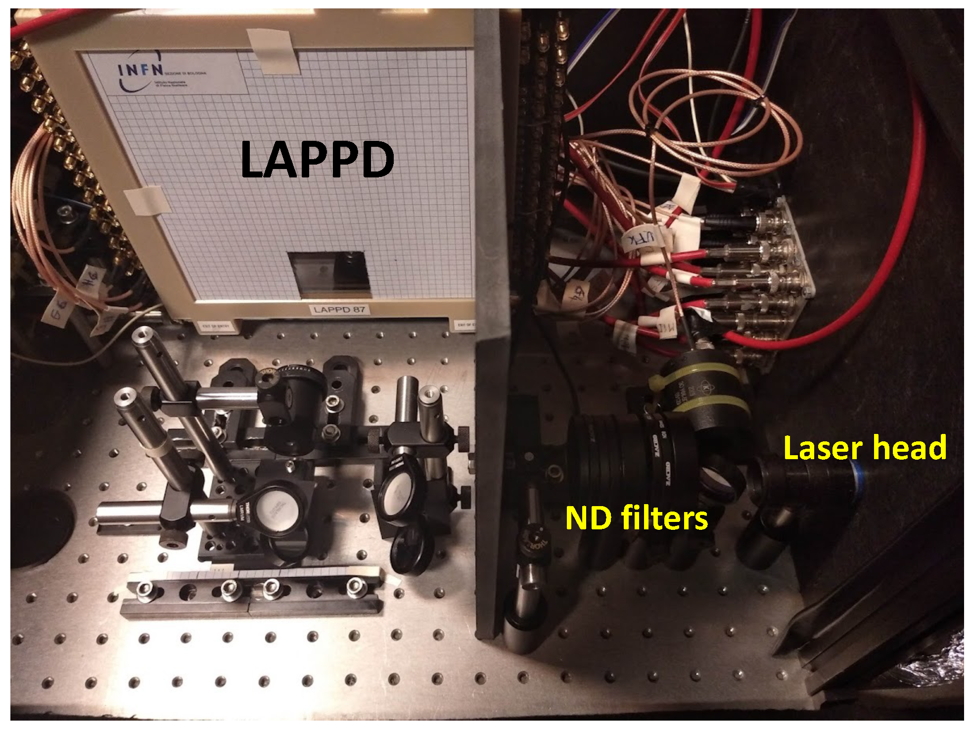
LAPPD Gen-I and Gen-II tiles were first tested in the laboratory using a free-space PICOPOWER
-LD laser produced by ALPHALAS [
14], with 405 nm wavelength and a tunable repetition rate from 1 Hz up to 50 MHz.
Figure 1 shows a picture of the laboratory setup.
The pulse width of the laser was measured by the company prior to shipment to have an RMS of 11.7 ps, while the jitter between the laser pulse and the laser trigger was precisely measured in the laboratory to have an RMS of 3.4 ps. The signals produced by the LAPPD were acquired using a CAEN v1742 digitiser [
15] equipped with DRS4 chips [
16], for a total of 32 channels. The digitiser has a bandwidth of 500 MHz and a maximum sampling rate of 5 GS/s with 1024 points per channel. The digitiser was provided with precalibration constants by the factory. However, the calibration quality was found unsatisfactory for the level of precision required by our studies and a recalibration was performed according to the strategy described in Ref. [
17], with some minimal improvements. To check the goodness of the calibration, pulses with a few ns rise time were generated with a waveform generator, split in two and sent to distinct channels of the board. The RMS of the time difference between the signals was measured to be about 2 ps when the two signals were close in time and about 4 ps when one of the two signals was delayed by 100 ns with respect to the other. In all studies presented in this paper, timestamps are calculated using two points on the rising front around 50% of the pulse height.
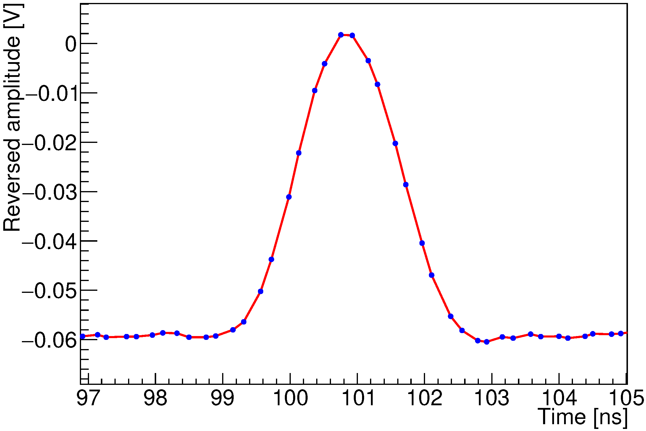
Performances of the LAPPDs with single PEs were measured by attenuating the laser pulse with neutral-density (ND) filters until the amount of non-empty events was about 3%, ensuring that the vast majority were events with a single-PE signal. A typical LAPPD Gen-I pulse shape for a single PE is shown in
Figure 2. The 20–80% risetime is about 700 ps and the pulse FWHM is about 1.8 ns.
When using the Gen-I LAPPD, the position of the laser spot (about 1 mm wide) was tuned to maximise the amplitude of one delay-line anode strip (about 7 mm wide), whereas for Gen-II, the laser was pointed towards the centre of a single capacitively coupled anode pixel (about
cm
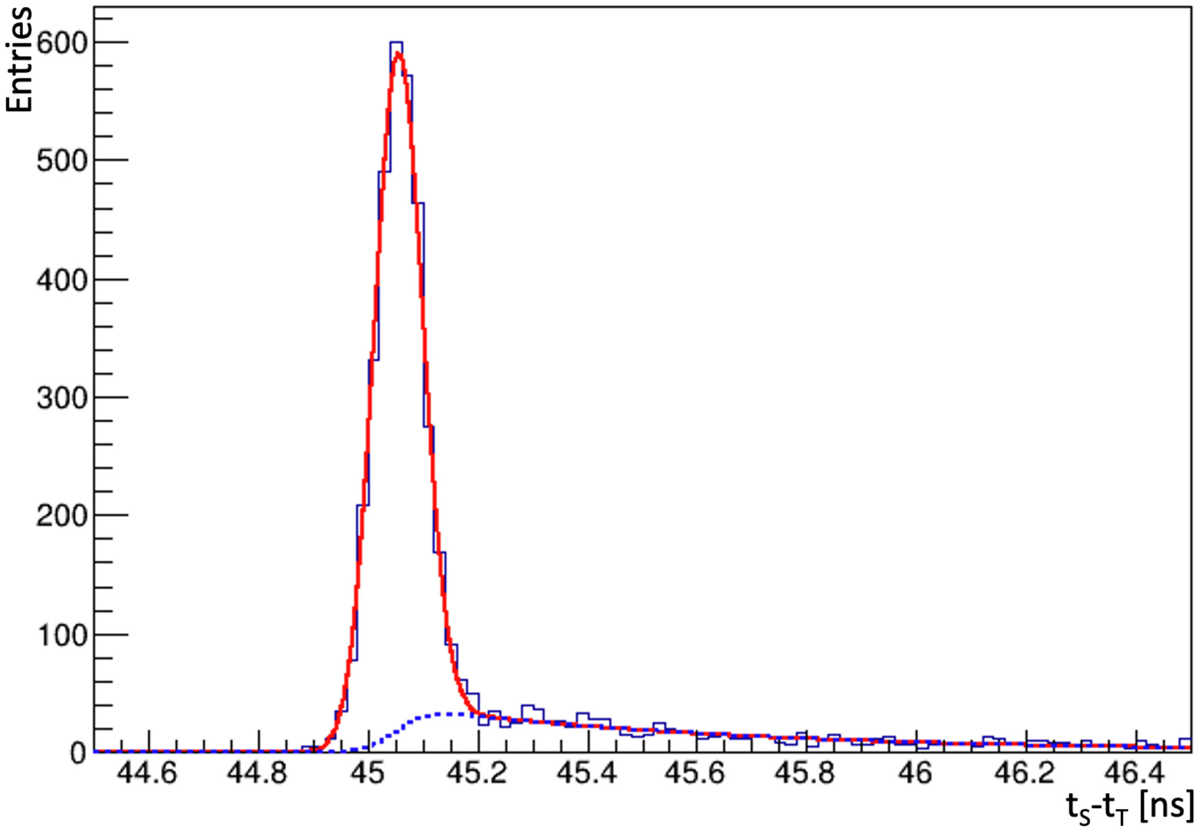
in size). With the Gen-I device, the difference between the time of the LAPPD signal, obtained by averaging the timestamps of both ends of the delay-line anode strip, and the laser trigger was used to measure the time resolution. The distribution of time difference for single-PE events showed a peaked core component plus a tail, due to PEs that bounced on the MCP surface before being captured inside pores by the electric field (backscattered PEs). As an example,
Figure 3 shows the time-difference distribution obtained with the LAPPD Gen-I for single-PE events, when applying a voltage bias of 100 V on the PC and 900 V between the two faces of the MCP wafers. The sum of a Gaussian function (describing the core of the distribution) and an exponential tail convolved with the same Gaussian function (describing the component of backscattered PEs) is fitted to the data. From the result of the best fit, the time resolution of the core component and the number of backscattered PEs are determined.
A relevant dependence of the time-difference distribution and the voltage bias applied to the PC is observed. The width of the core of the distribution is narrowed by increasing the PC bias, but that also causes an increase in the contribution of the tail component. At 900 V per MCP, the core resolution for single PEs of the LAPPD Gen-I varies from about 65 ps at 50 V PC bias, to about 35 ps for 200 V PC bias. Unless stated otherwise, time resolutions are quoted after subtracting experimental effects such as laser-pulse width and digitiser resolution. In the same range of voltage biases, the contribution of backscattered PEs ranges approximately between 10 and 30%. Fixing the PC bias to 200 V, a scan of the bias applied to the MCPs was also performed, finding the best core resolution to be 31 ps when applying 870 V per MCP, with an average amplitude measured at the single-strip end of about 32 mV. The resolution of the time difference between the signals from the two ends of the delay-line anode strip was measured to be about 17 ps. Higher PC voltages were also tested, but no sizeable improvements in single-PE time resolution were found. Similar studies were conducted by other groups in the past. For example, in Ref. [
18] a time resolution of about 50 ps for single PEs, limited by electronics, is reported. Our results are significantly better, and we attribute this mainly to an improved control of the readout electronics and to the optimisation of working voltage biases.
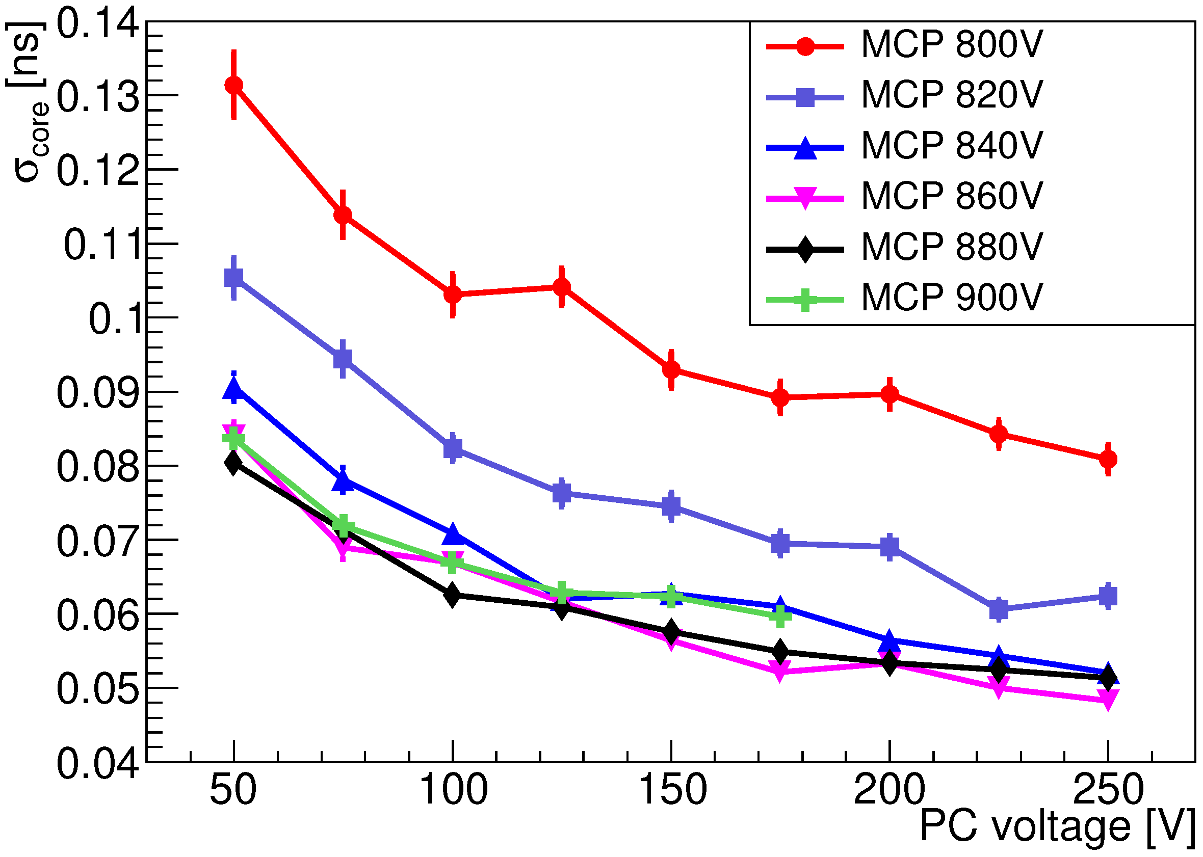
In the case of the Gen-II, a two-dimensional scan of PC and MCP voltages was performed to obtain the best core resolution for single PEs, achieving about 50 ps with 250 V bias for the PC and 860 V for the MCPs (see
Figure 4).
Signal amplitudes for PEs in the tail of the time-difference distribution are found to be significantly lower than those in the Gaussian core. By applying minimal requirements on the amplitude of the signal pulses, it is possible to reduce the tail component at the cost of some efficiency loss. The optimal working point between efficiency loss and number of backscattered PEs must be chosen depending on the physics application. Since the LAPPD Gen-II has a pixelated anode, the effect of PEs associated with different positions across a pixel’s surface was studied. The laser beam was defocused to uniformly illuminate the PC region corresponding to one pixel. The core resolution was evaluated again for single-PE events. The resolutions obtained with defocused and focused laser beams were subtracted in quadrature, allowing for the contribution due to the size of the pixels to be estimated as approximately 24 ps.
To evaluate LAPPD performances when inserted within an ECAL module, a full Geant4 simulation [
19], notably taking into account the quantum efficiency as a function of the wavelength provided by Incom Inc., was used to predict the distribution of PEs produced in the LAPPD by electromagnetic showers originating from 5-GeV electrons impinging on the ECAL surface. The radial spread of the shower entering the LAPPD was predicted to have an RMS of 15 mm with about 20 charged particles (electrons and positrons) on average. For simplicity, it was assumed that all PEs were collected and amplified by the MCP stack. The laser beam was defocused, and the attenuation tuned to reproduce such conditions in the laboratory. The procedure to tune the laser intensity and obtain any given number of PEs was as follows. First, the individual attenuations of a set of ND filters were measured using the same laser system operated in continuous-wave mode and a calibrated photodiode. Then, appropriate filters were added with the laser system in pulsed mode until the rate of non-empty events corresponded to an average of one PE (about 63%). Finally, by removing filters of known attenuation, it was possible to select the required average number of PEs. The voltage settings were optimised to achieve the best time resolution for 20 particles. The LAPPD Gen-I showed time resolutions of approximately 12 ps, while the LAPPD Gen-II reached 8 ps. The difference between the two is due to the fact that the tested Gen-I LAPPD was equipped with a suboptimal PC that had only 5% quantum efficiency, a factor of about 6 lower than the tested Gen-II device. The configuration with the PC inhibited was emulated by reducing the number of PEs to that of ionisation electrons expected in the MCPs when traversed by the electromagnetic shower, assuming for simplicity that each charged particle produces a single initial electron. In this configuration, the Gen-II device showed a time resolution of approximately 19 ps (the same test was not made for Gen-I). It is important to note that these estimates do not take into account the effects due to fluctuations in the number of particles in the shower and their time spread.
A final set of tests performed in the laboratory was aimed at investigating the LAPPD behaviour in a high-rate environment. In the case of the Gen-I device, the laser-beam intensity was set to emulate the response of the LAPPD to electromagnetic showers due to 5-GeV electrons. The frequency of the laser pulses was varied from 500 Hz to 5 MHz. The time resolution of the device stayed approximately flat up to 100 kHz, where it was of about 15 ps. Time resolutions of approximately 50 and 100 ps were observed at 1 and 5 MHz, respectively. This deterioration is due to a well-known issue of MCP-PMTs that need long times to recharge the pores, causing a relevant reduction of signal amplitudes and consequently of signal-to-noise ratio. In fact, the average amplitudes at a single-strip end were measured to be about 160 mV at 500 Hz, 50 mV at 100 kHz, 10 mV at 1 MHz and 5 mV at 5 MHz. Considering that the risetime is order of 1 ns and the noise of the readout electronics is approximately 0.5 mV, it is possible to conclude that the time resolutions at 1 and 5 MHz were largely limited by the small signal-to-noise ratio.
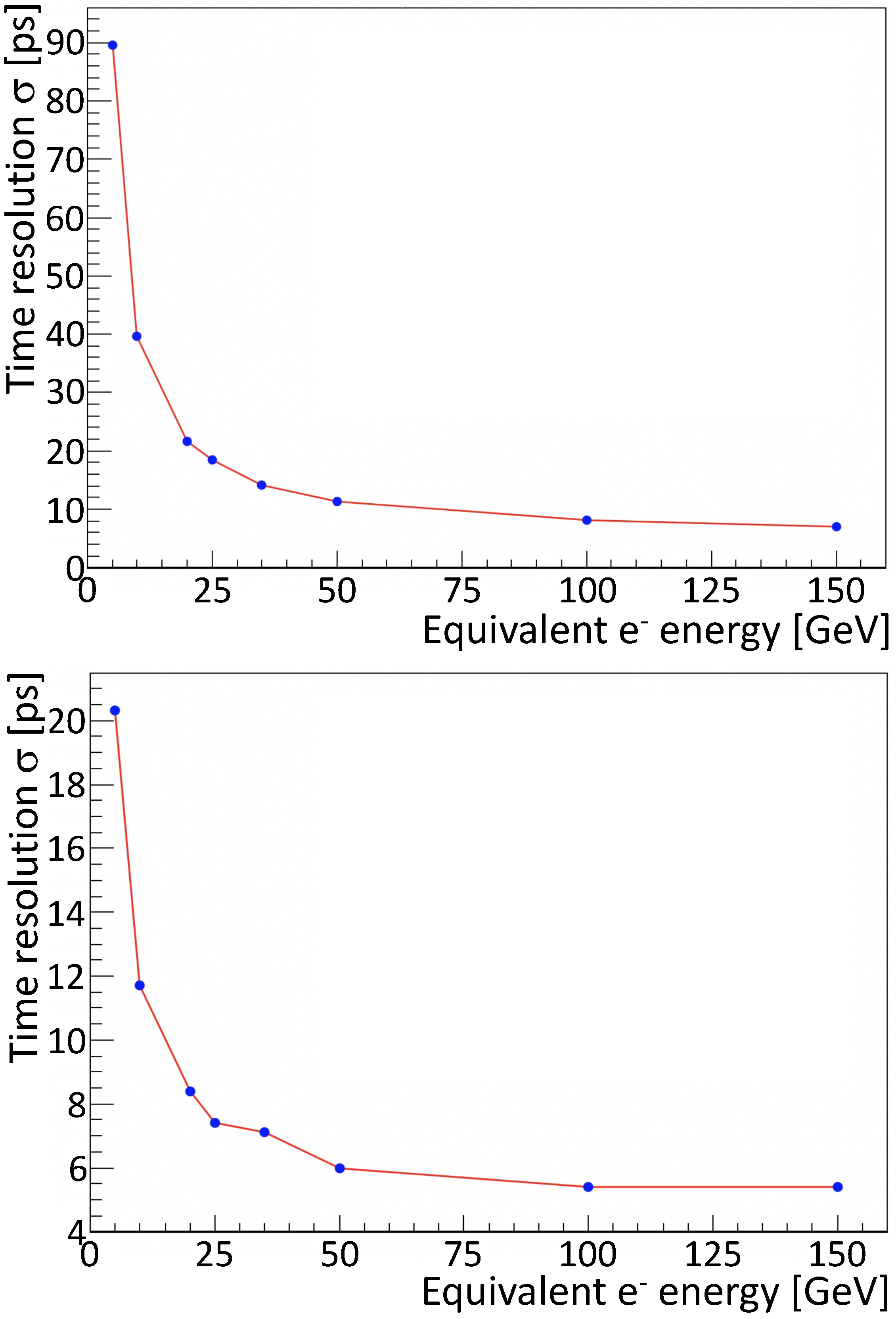
A different test was performed with the LAPPD Gen-II. Accurate simulations were used to determine the amount of ionisation electrons produced in the timing-layer detector with the PC inhibited for
collision events at a luminosity of
cm
s
. The simulations indicated that in the hottest regions of the ECAL, an average of 30 MHz/cm
of charged particles traverse the timing layer. A green LED light was used to constantly illuminate the LAPPD Gen-II surface, and its power tuned to reproduce the required average of charged particles per unit area. Defocused laser pulses were used to reproduce the effect of electromagnetic showers due to electrons of different energies, from 5 GeV up to 100 GeV, impinging on the LAPPD with the PC inhibited. The time resolution, corresponding to 5 GeV electrons, obtained with the LED turned off, was 27 ps, with an average signal amplitude of about 320 mV. Turning on the LED light, the signal amplitude was reduced by approximately a factor of 50, down to 6 mV, and the time resolution degraded to approximately 90 ps. Time resolutions below 20 ps were observed for the emulation of electromagnetic showers due to primary electrons of energies above 20 GeV. The same test was repeated with a UFK-5G-2D MCP-PMT produced by Katod LLC [
20] and equipped with two 0.3-mm thick MCPs with pores of 6µm. With the LED turned off, a time resolution of 15 ps was observed. The resolution degraded to only slightly above 20 ps when turning on the LED light, with a reduction in average signal amplitude by only a factor 8, from 190 mV to 24 mV.
Figure 5 shows the time resolution obtained with the LED light turned on as a function of the emulated primary-electron energy for both LAPPD Gen-II and UFK-5G-2D. Additionally, in this study, the fluctuations in the number of particles in the electromagnetic shower and their time spread were not taken into account. Although such a comparative study does not allow definitive conclusions to be drawn, due to the many differences between LAPPD and UFK photomultipliers, it provides an indication that smaller pore sizes could be a useful leverage to cope with high rates. Ongoing studies with a 10 µm LAPPD will be reported in a future publication.
3. DESY Beamtest
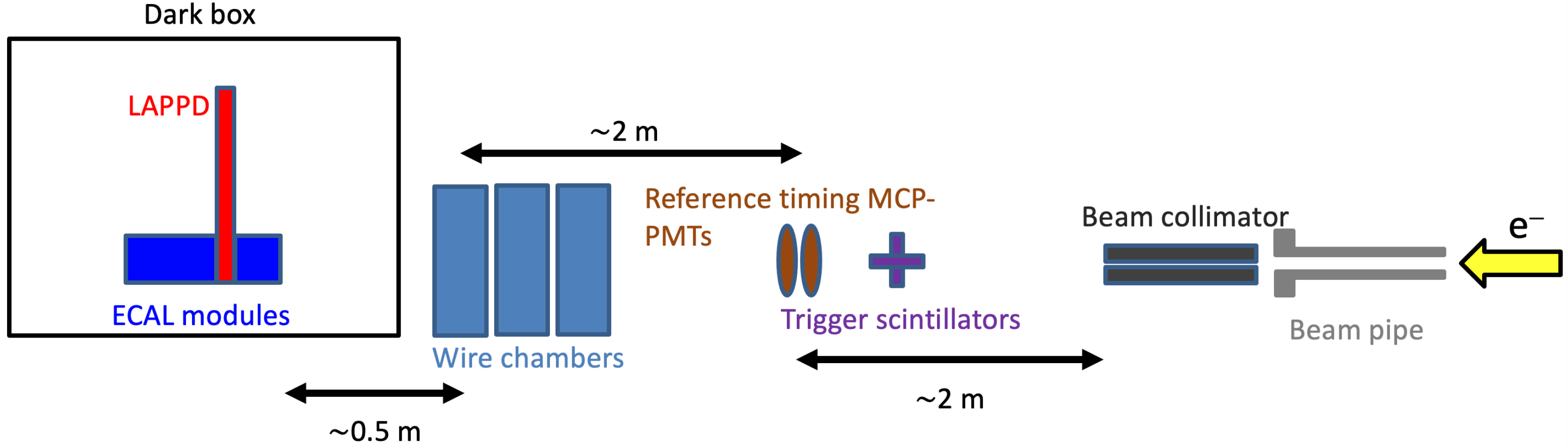
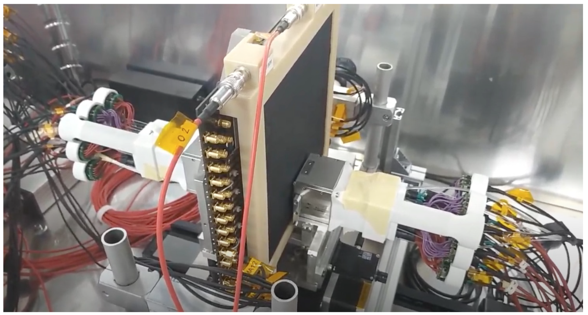
In
Figure 6, a schematic view of the experimental setup used for the testbeam at DESY is shown, while a picture of the LAPPD installed within the two sections of the ECAL module is shown in
Figure 7.
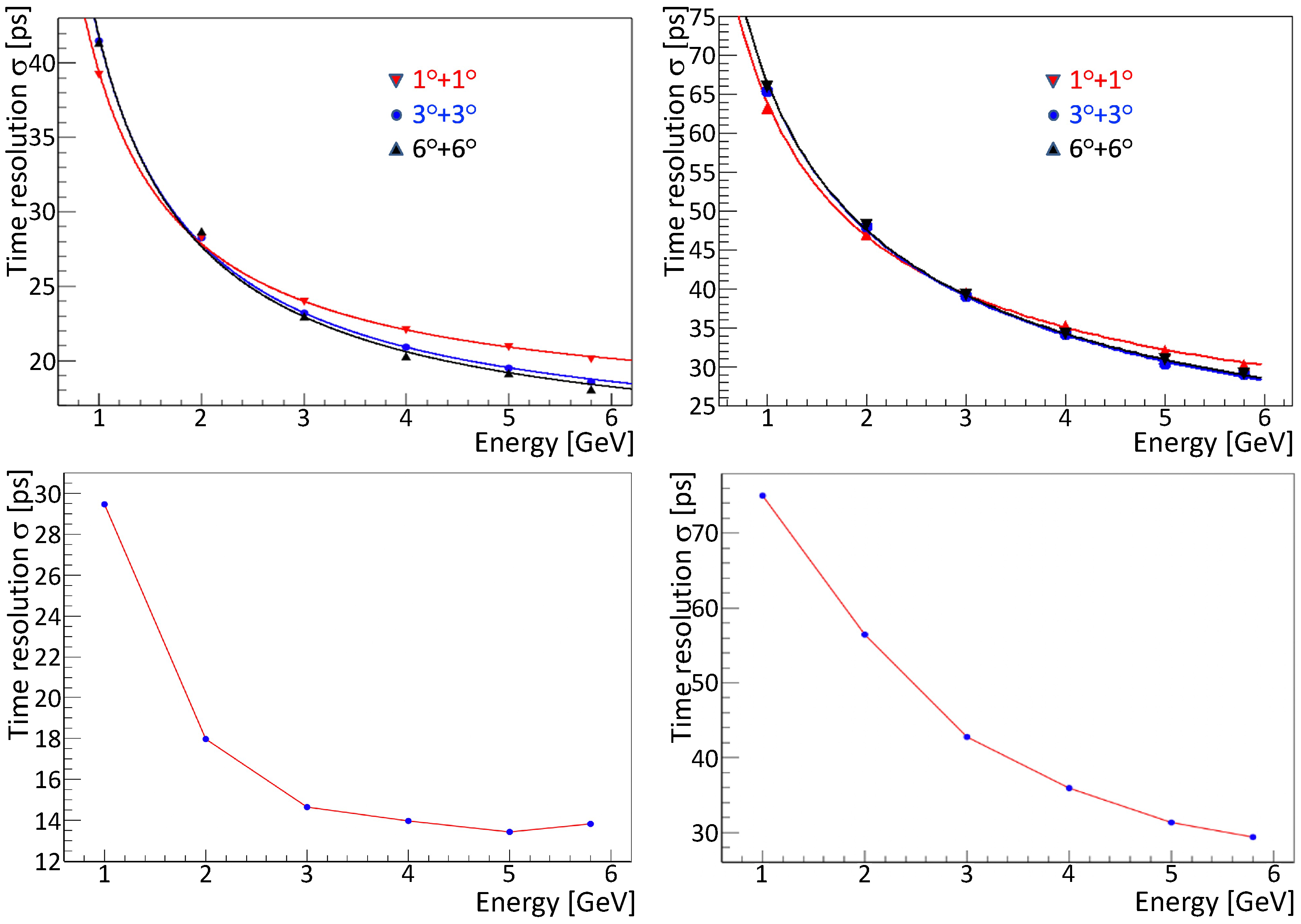
Electrons pointing to the ECAL module were selected using a passive absorber as a collimator. The trigger signal was given by two plastic scintillators in coincidence, and two MCP-PMTs were used to determine the reference time of the incoming electrons, which was found to have a resolution of 12 ps. Three Delay Wire Chambers (DWCs) were used to measure the position of the incoming electrons. The LAPPD was inserted between two sections of the ECAL module, whose front section corresponded to approximately 7 radiation lengths. The system composed of the LAPPD and the ECAL module was inserted inside a dark box and could be rotated to form angles with the electron beam from 0° to 6° in both the horizontal and vertical plane, corresponding to the typical range of incidence angles for particles impinging on the LHCb ECAL surface. Signals produced by the reference MCP-PMTs and the LAPPD were acquired using the same CAEN v1742 digitiser used in the laser-beam tests. Data were taken either with the PC enabled or inhibited. To inhibit the PC, an inverse bias of 50 V was applied between the PC and the first MCP of the Chevron stack. In the configuration with the PC enabled, voltage settings were optimised to achieve the best resolution for electrons with energy of 5 GeV. For the Gen-I device, the optimised biases applied to the PC and MCPs were 400 V and 765 V, respectively. In the case of the Gen-II device, 250 V was applied to the PC and 715 V to the MCPs. In the configuration with the PC inhibited, the optimised biases applied to the MCPs were 900 V and 850 V for the Gen-I and Gen-II devices, respectively. Top plots in
Figure 8 show the time resolution of the Gen-I device, with either PC activated or inhibited, as a function of the energy of primary electrons impinging with different angles on the ECAL module. Time resolutions as good as 19 ps (with PC enabled) and 29 ps (with PC inhibited) were measured for primary electrons with an energy of 5.8 GeV. The time resolution
obtained with the PC enabled shows a dependence on the energy of primary electrons
E that is empirically found to be described reasonably well by the function
, with
E in GeV,
ps GeV and
ps. No difference in time resolution is observed between configurations with incidence angles of 3° and 6° (applied on both horizontal and vertical planes). A slight degradation of the time resolution is observed when reducing the incidence angle to 1°. In the PC-inhibited case, the dependence of the time resolution from the energy of primary electrons is described reasonably well by the empirical function
, with
E in GeV,
ps GeV
and
ps. However, additional tests with higher electron energies are necessary to properly understand the asymptotic performance. In the case of LAPPD Gen-II, only the configuration with incidence angles of 3° in the horizontal and vertical planes was taken into account. Time resolutions as good as 14 ps and 30 ps were measured with the PC enabled and inhibited, respectively. Time resolutions as a function of the energy of primary electrons are shown in the bottom plots of
Figure 8. Due to the higher quantum efficiency of the PC, with respect to the Gen-I device, Gen-II performances were slightly better when operating with the PC enabled. Performances with PC inhibited are similar between the two devices, with the LAPPD Gen-I performing slightly better at lower energies.


 ,
, 


