Temperature Effects on the HOPG Intercalation Process

 ,
, 
 and
and 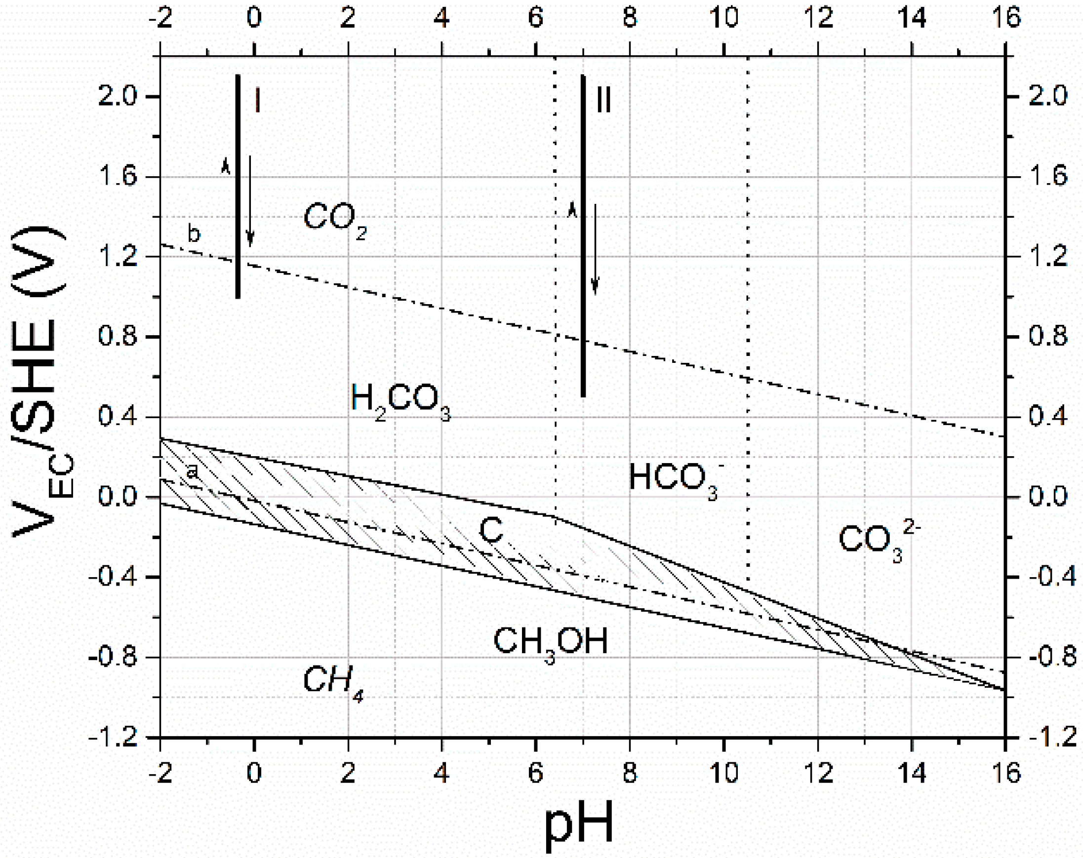
Abstract
1. Introduction
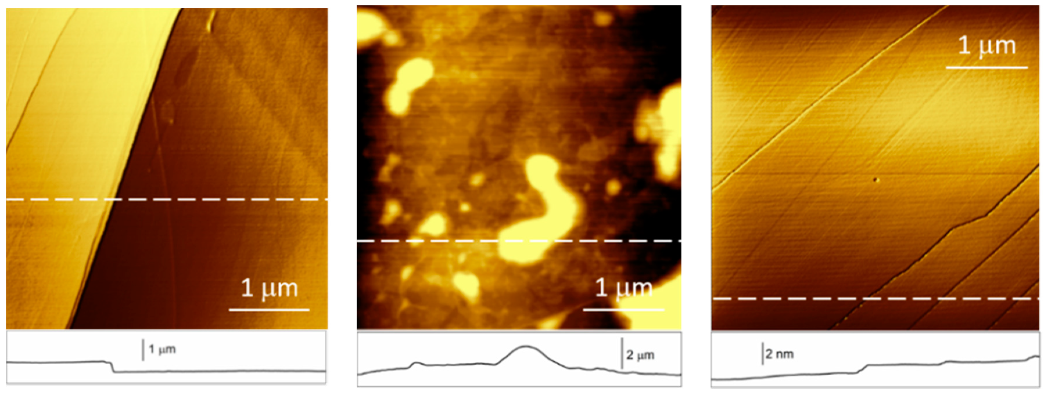
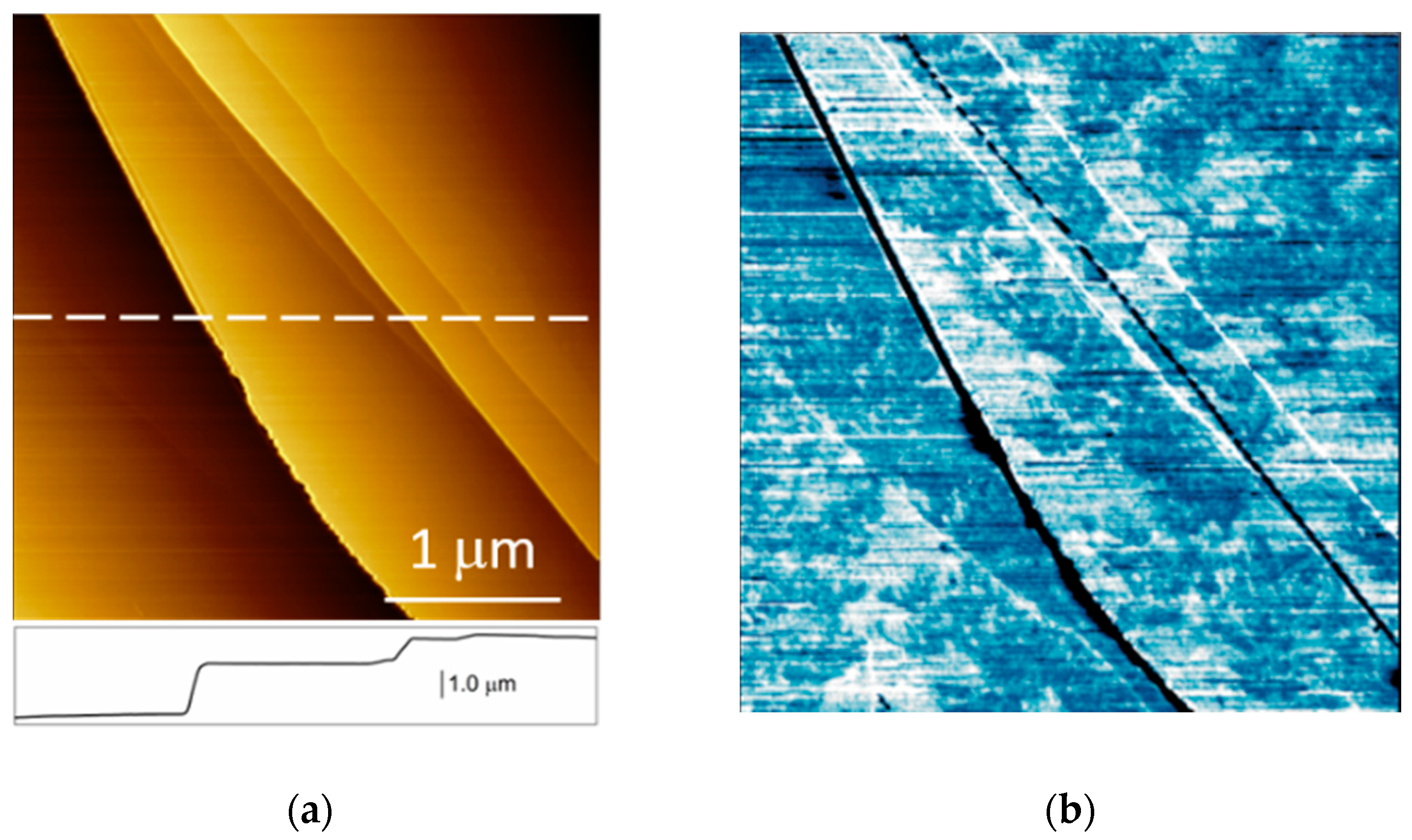
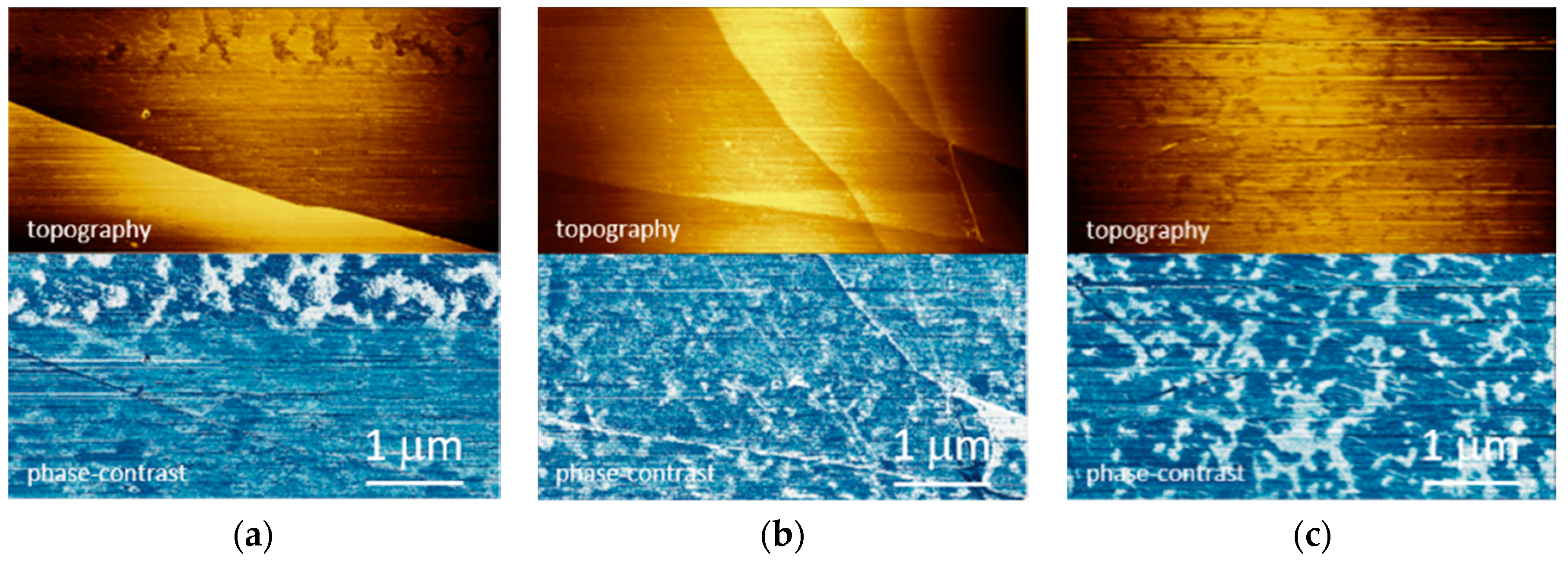
2. Results and Discussion
3. Materials and Methods
4. Conclusions
Author Contributions
Funding
Conflicts of Interest
References
- Shi, P.C.; Guo, J.P.; Liang, X.; Cheng, S.; Zheng, H.; Wang, Y.; Chen, C.H.; Xiang, H.F. Large-scale production of high-quality graphene sheets by a non-electrified electrochemical exfoliation method. Carbon 2018, 126, 507–513. [Google Scholar] [CrossRef]
- Hofmann, M.; Chiang, W.-Y.; Nguyễn, T.D.; Hsieh, Y.-P. Controlling the properties of graphene produced by electrochemical exfoliation. Nanotechnology 2015, 26, 335607. [Google Scholar] [CrossRef] [PubMed]
- Kamali, A.R.; Fray, D.J. Large-scale preparation of graphene by high temperature insertion of hydrogen into graphite. Nanoscale 2015, 7, 11310–11320. [Google Scholar] [CrossRef] [PubMed]
- Nuvoli, D.; Valentini, L.; Alzari, V.; Scognamillo, S.; Bon, S.B.; Piccinini, M.; Illescas, J.; Mariani, A. High concentration few-layer graphene sheets obtained by liquid phase exfoliation of graphite in ionic liquid. J. Mater. Chem. 2011, 21, 3428–3431. [Google Scholar] [CrossRef]
- Yang, S.; Ricciardulli, A.G.; Liu, S.; Dong, R.; Lohe, M.R.; Becker, A.; Squillaci, M.A.; Samorì, P.; Müllen, K.; Feng, X. Ultrafast Delamination of Graphite into High-Quality Graphene Using Alternating Currents. Angewandte Chem. 2017, 56, 6669–6675. [Google Scholar] [CrossRef] [PubMed]
- Goss, C.A.; Brumfield, J.C.; Irene, E.A.; Murray, R.W. Imaging the incipient electrochemical oxidation of highly oriented pyrolytic graphite. Anal. Chem. 1993, 65, 1378–1389. [Google Scholar] [CrossRef]
- Bussetti, G.; Yivlialin, R.; Alliata, D.; Li Bassi, A.; Castiglioni, C.; Tommasini, M.; Casari, C.S.; Passoni, M.; Biagioni, P.; Ciccacci, F.; et al. Disclosing the Early Stages of Electrochemical Anion Intercalation in Graphite by a Combined Atomic Force Microscopy/Scanning Tunneling Microscopy Approach. J. Phys. Chem. C 2016, 120, 6088–6093. [Google Scholar] [CrossRef]
- Alliata, D.; Kötz, R.; Haas, O.; Siegenthaler, H. In Situ AFM Study of Interlayer Spacing during Anion Intercalation into HOPG in Aqueous Electrolyte. Langmuir 1999, 15, 8483–8489. [Google Scholar] [CrossRef]
- Yivlialin, R.; Bussetti, G.; Magagnin, L.; Ciccacci, F.; Duò, L. Temporal analysis of blister evolution during anion intercalation in graphite. Phys. Chem. Chem. Phys. 2017, 19, 13855–13859. [Google Scholar] [PubMed]
- Hathcock, K.W.; Brumfield, J.C.; Goss, C.A.; Irene, E.A.; Murray, R.W. Incipient Electrochemical Oxidation of Highly Oriented Pyrolitic Graphite: Correlation between Surface Blistering and Electrolyte Anion Intercalation. Anal. Chem. 1995, 67, 2201–2206. [Google Scholar] [CrossRef]
- Yivlialin, R.; Magagnin, L.; Duò, L.; Bussetti, G. Blister evolution time invariance at very low electrolyte pH: H2SO4/graphite system investigated by electrochemical atomic force microscopy. Electrochim. Acta 2018, 276, 352–361. [Google Scholar] [CrossRef]
- Rodrigues, M.-T.F.; Sayed, F.N.; Gullapalli, H.; Ajayan, P.M. High-temperature solid electrolyte interphases (SEI) in graphite electrodes. J. Power Sources 2018, 381, 107–115. [Google Scholar] [CrossRef]
- Kulova, T.L.; Skundin, A.M.; Nizhnikovskii, E.A.; Fesenko, A.V. Temperature effect on the lithium diffusion rate in graphite. Russ. J. Electrochem. 2006, 42, 259–262. [Google Scholar] [CrossRef]
- Levi, M.D.; Wang, C.; Aurbach, D.; Chvoj, Z. Effect of temperature on the kinetics and thermodynamics of electrochemical insertion of Li-ions into a graphite electrode. J. Electroanal. Chem. 2004, 562, 187–203. [Google Scholar] [CrossRef]
- Leng, F.; Tan, C.M.; Pecht, M. Effect of Temperature on the Aging rate of Li Ion Battery Operation above Room Temperature. Sci. Rep. 2015, 5, 12967. [Google Scholar] [CrossRef] [PubMed]
- Pereira-Ramos, J.-P.; Messina, R.; Piolet, C.; Devynck, J. Investigation of lithium intercalation materials with organic solvent and molten salts as electrolytes at temperatures between 60 and 175 °C. J. Power Sources 1987, 20, 221–230. [Google Scholar] [CrossRef]
- Gründler, P. History of Modern Thermoelectrochemistry. In In-Situ Thermoelectrochemistry. Monographs in Electrochemistry; Springer: Berlin/Heidelberg, Germany, 2015. [Google Scholar]
- Khateeb, S.A.; Farid, M.M.; Selman, J.R.; Al-Hallaj, S. Design and simulation of a lithium-ion battery with a phase change material thermal management system for an electric scooter. J. Power Sources 2004, 128, 292–307. [Google Scholar] [CrossRef]
- Varcoe, J.R.; Atanassov, P.; Dekel, D.R.; Herring, A.M.; Hickner, M.A.; Kohl, P.A.; Kucernak, A.R.; Mustain, W.E.; Nijmeijer, K.; Scott, K.; et al. Anion-exchange membranes in electrochemical energy systems. Energy Environ. Sci. 2014, 7, 3135–3191. [Google Scholar] [CrossRef]
- Jagadeesh, M.S.; Calloni, A.; Denti, I.; Goletti, C.; Ciccacci, F.; Duò, L.; Bussetti, G. The effect of cyclic voltammetry speed on anion intercalation in HOPG. Surf. Sci. 2019, 681, 111–115. [Google Scholar] [CrossRef]
- Jagadeesh, M.S.; Bussetti, G.; Calloni, A.; Yivlialin, R.; Brambilla, L.; Accogli, A.; Gibertini, E.; Alliata, D.; Goletti, C.; Ciccacci, F.; et al. Incipient Anion Intercalation of Highly Oriented Pyrolitic Graphite Close to the Oxygen Evolution Potential: A Combined X-ray Photoemission and Raman Spectroscopy Study. J. Phys. Chem. C 2019, 123, 1790–1797. [Google Scholar] [CrossRef]
- Bussetti, G.; Campione, M.; Riva, M.; Picone, A.; Raimondo, L.; Ferraro, L.; Hogan, C.; Palummo, M.; Brambilla, A.; Finazzi, M.; et al. Stable Alignment of Tautomers at Room Temperature in Porphyrin 2D Layers. Adv. Funct. Mater. 2014, 24, 958–963. [Google Scholar] [CrossRef]


© 2019 by the authors. Licensee MDPI, Basel, Switzerland. This article is an open access article distributed under the terms and conditions of the Creative Commons Attribution (CC BY) license (http://creativecommons.org/licenses/by/4.0/).
Share and Cite
Bussetti, G.; Yivlialin, R.; Goletti, C.; Zani, M.; Duò, L. Temperature Effects on the HOPG Intercalation Process. Condens. Matter 2019, 4, 23. https://doi.org/10.3390/condmat4010023
Bussetti G, Yivlialin R, Goletti C, Zani M, Duò L. Temperature Effects on the HOPG Intercalation Process. Condensed Matter. 2019; 4(1):23. https://doi.org/10.3390/condmat4010023
Chicago/Turabian StyleBussetti, Gianlorenzo, Rossella Yivlialin, Claudio Goletti, Maurizio Zani, and Lamberto Duò. 2019. "Temperature Effects on the HOPG Intercalation Process" Condensed Matter 4, no. 1: 23. https://doi.org/10.3390/condmat4010023
APA StyleBussetti, G., Yivlialin, R., Goletti, C., Zani, M., & Duò, L. (2019). Temperature Effects on the HOPG Intercalation Process. Condensed Matter, 4(1), 23. https://doi.org/10.3390/condmat4010023