
Article

Waste Bakelite Thermoset as Slag Foaming and Iron Oxide Reduction Agents in EAF Steelmaking: Advancing Fossil Fuel Reduction in Steel Industry

by
Thanaporn Chandransu
,
Krishmanust Sunankingphet
and
Somyote Kongkarat
*
Research Unit in Sustainable Materials and Circular Economy, Faculty of Science and Technology, Thammasat University, Khlong Luang 12120, Thailand
*
Author to whom correspondence should be addressed.
Recycling 2026, 11(6), 97; https://doi.org/10.3390/recycling11060097
Submission received: 13 April 2026 / Revised: 13 May 2026 / Accepted: 25 May 2026 / Published: 27 May 2026

Abstract

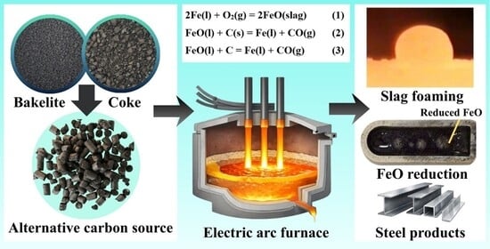
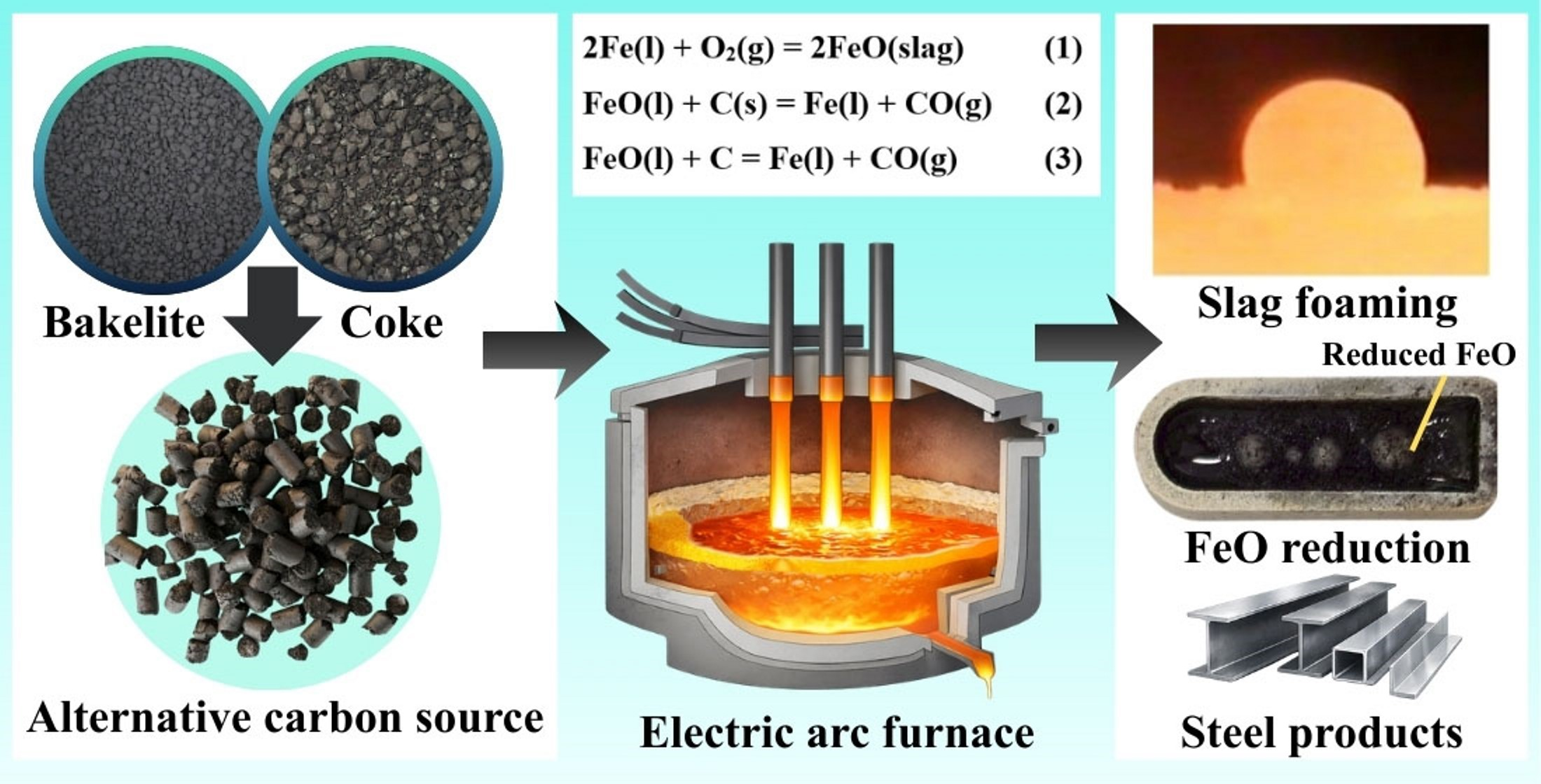
This study evaluates the feasibility of using waste Bakelite thermoset as a slag foaming and iron oxide reduction agent in electric arc furnace (EAF) steelmaking. Bakelite was blended with metallurgical coke at three ratios (10–30 wt% Bakelite), designated as Blend#1 to Blend#3. All carbon samples were heat-treated at 1000 °C under an argon atmosphere to produce char and were subsequently assessed for carbon–slag interactions at 1550 °C, with emphasis on slag foaming behavior and FeO reduction. The incorporation of Bakelite increased the total carbon content and significantly altered coke ash chemistry, marked by reduced SiO2 and Al2O3 and increased CaO contents. Structural analysis revealed enhanced carbon graphitization with increasing Bakelite proportion. Among all samples, Blend#3 exhibited the most stable and pronounced slag foaming, achieving a maximum volume ratio of approximately 1.7 and forming uniformly distributed, multi-sized gas bubbles within the slag. FeO reduction improved with Bakelite addition, with metallization degrees of 77.30, 81.65, 80.56, and 84.41% for coke, Blend#1, Blend#2, and Blend#3, respectively. Blend#3 produced the lowest total gas emission (186,000 ppm), approximately 30% lower than that of pure coke. These findings demonstrate that waste Bakelite thermoset is an effective low-carbon alternative carbon source for EAF steelmaking, enhancing FeO reduction, slag foaming stability, and overall environmental performance.

Graphical Abstract

1. Introduction

Slag foaming is a critical operation in electric arc furnace (EAF) steelmaking. A stable foamy slag layer reduces heat losses, protects refractories from arc radiation, enhances impurity absorption, and improves steel cleanliness, thereby increasing energy efficiency and reducing operating costs [1,2,3]. Therefore, achieving stable and homogeneous slag foams is essential for efficient and sustainable steel production. Slag foaming is governed by gas generation, mainly CO from FeO–C reactions, and slag foamability, which depends on viscosity (μ), surface tension (σ), density (ρ), solid fraction, and melt structure [4,5,6,7]. Foamability is commonly quantified by the foaming index (Σ), defined as the ratio of foam height (H) to superficial gas velocity (U), Σ = H/U [4,5]. Lower FeO contents increase slag viscosity and foam stability (stabilizes bubbles), whereas excessive viscosity hinders refining kinetics and mass transfer [8,9,10,11]. Optimal FeO ranges enable sufficient CO generation while maintaining moderate viscosity, avoiding thin, unstable foams and excessive oxidizing losses [10,11]. FeO reduction by solid or dissolved carbon involves FeO transport to reaction interfaces, interfacial reactions producing CO/CO2, and gas diffusion through boundary layers around carbon particles. The rate-controlling step varies with FeO content: FeO mass transfer dominates at low FeO (<5 wt%), while gas–slag interfacial reactions and gas transport control at intermediate FeO levels (5–40 wt%) [12].
Metallurgical coke is widely used as both a carbon source and reductant in EAFs but contributes substantially to greenhouse gas emissions from coal carbonization and in-furnace oxidation [13,14,15]. Coke typically contains 70–90 wt% carbon with residual ash, volatiles, and sulfur, and its properties vary with production route. Developing alternative carbon materials to replace fossil-derived coke is therefore essential for reducing the carbon footprint of steelmaking and achieving carbon-neutrality targets. Numerous studies have reported sustainability-oriented strategies in steelmaking aimed at reducing dependence on fossil carbon and lowering overall environmental impact by incorporating waste-derived and renewable materials [16,17,18,19,20,21,22,23,24,25,26,27,28,29,30,31]. Waste polymers have been demonstrated to partially or fully replace conventional carbon sources in both steel recarburization processes [16,17,18] and carbon–slag reactions associated with slag foaming and refining [19,20,21,22,23,24]. In particular, blending high-density polyethylene (HDPE) and rubber tire wastes with coke has been shown to enhance carbon–slag interactions at steelmaking temperatures (~1550 °C), resulting in higher rates of CO and CO2 evolution and more stable and voluminous slag foaming behavior [19,20,21,22,23,24]. Compared with coke alone, the use of waste polymers also improves FeO reduction efficiency in slag, which has been attributed to the additional reducing gases, such as CH4 and H2, released during polymer thermal decomposition, acting synergistically with solid carbon to accelerate reduction kinetics [22,23,24]. In parallel, biomass resources [25], including palm shell [26], rice husk [27], and rice straw [28], have been investigated as renewable carbon alternatives for metallurgical applications. Palm shell was reported to function effectively as both a slag foaming agent and FeO reductant in molten slag at steelmaking temperatures [26], while rice husk has been successfully utilized as a combined source of silica and carbon for ferrosilicon production. In this case, simultaneous reduction of SiO2 from rice husk ash and FeO from mill scale at ~1550 °C enabled the synthesis of ferrosilicon alloys with Si contents as high as 81.9–88.4 wt% [27]. Collectively, these studies demonstrate the technical feasibility and metallurgical benefits of using waste polymers and biomass-derived carbons as sustainable substitutes for conventional coke in high-temperature iron and steelmaking processes.
Bakelite is a carbon-rich thermoset polymer typically filled with calcium carbonate (CaCO3), which decomposes to CaO during high-temperature processing. It has been widely used in household and industrial products such as cookware handles, electrical plugs, electronic components, jewelry, billiard balls, and vintage telephones due to its excellent thermal stability, mechanical strength, and electrical insulation properties. However, this same thermal stability prevents Bakelite from being recycled through conventional remelting or reshaping routes, resulting in a significantly lower recycling rate compared with common thermoplastics such as HDPE, LDPE, and PET. As a consequence, most waste Bakelite is currently landfilled or incinerated, highlighting the need to develop alternative recycling and upcycling strategies that can recover its carbon content and inorganic fillers for value-added industrial applications. In the iron and steel industry, waste Bakelite has attracted interest as an alternative carbon resource and functional additive. Previous studies demonstrated its effectiveness as a recarburizer for liquid steel [29] and as a reductant for FeO in ironmaking processes [30,31]. The CaCO3-derived CaO present in Bakelite alters ash chemistry when blended with coke, increasing basicity and acting as a fluxing agent that lowers the melting point of the interfacial ash layer between solid carbon and molten steel. This promotes the formation of a more fluid interfacial layer, which can be readily displaced from the reaction interface, thereby improving contact between carbon and liquid steel and enhancing carbon dissolution kinetics at temperatures around 1550 °C [29,32]. In iron oxide reduction experiments conducted at approximately 1450 °C, raw Bakelite was reported to produce direct reduced iron pellets without clear metal–slag separation, whereas Bakelite char facilitated the formation of discrete iron nuggets and slag phases [30], indicating that thermal pretreatment strongly influences its metallurgical behavior. Despite these promising applications, the potential use of waste Bakelite as a slag foaming agent in electric arc furnace (EAF) steelmaking has not yet been investigated, representing a novel opportunity for its valorization within high-temperature metallurgical processes.
This study investigates the utilization of thermoset Bakelite waste as a carbonaceous additive in electric arc furnace (EAF) steelmaking. Bakelite waste was blended with metallurgical coke at three ratios and heat-treated to produce carbonaceous materials. The reactivity of the carbon blends toward molten slag at 1550 °C was examined to evaluate their potential for enhancing slag foaming and FeO reduction in the molten slag. The influence of plastic filler (CaCO3) present in Bakelite on slag foaming behavior was evaluated. This approach provides a sustainable pathway to reduce fossil fuel consumption and greenhouse gas emissions in steel production.

2. Results and Discussion

2.1. Foaming of Molten Slag

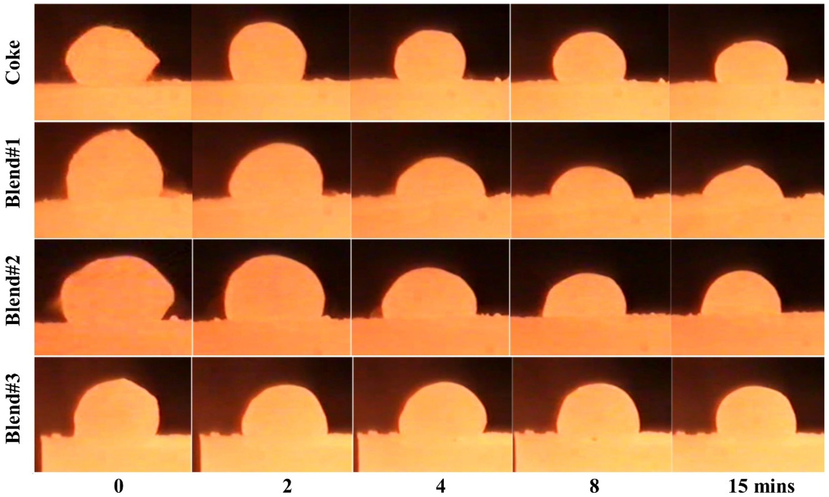
In the present study, Bakelite was blended with coke at three proportions (10–30 wt% Bakelite), referred to as Blend#1 to Blend#3, and used as the carbonaceous material. Their interaction with molten slag was investigated at 1550 °C for 15 min. The morphological evolution of slag droplets reacting with coke and Blend#1–Blend#3 is presented in Figure 1. All samples showed good performance, forming nearly spherical droplets whose size and shape changed over time depending on the amount of CO/CO2 gas released or retained within the droplet during the reaction. The foaming of molten slag typically developed within the first minute of reaction and gradually subsided thereafter. For the coke sample, the initial slag droplets were relatively small and progressively decreased in size, while Blend#1–Blend#3 formed larger droplets overall. To further clarify the slag foaming behavior, the volume ratio (Vt/V0) was determined based on the temporal change in droplet volume.
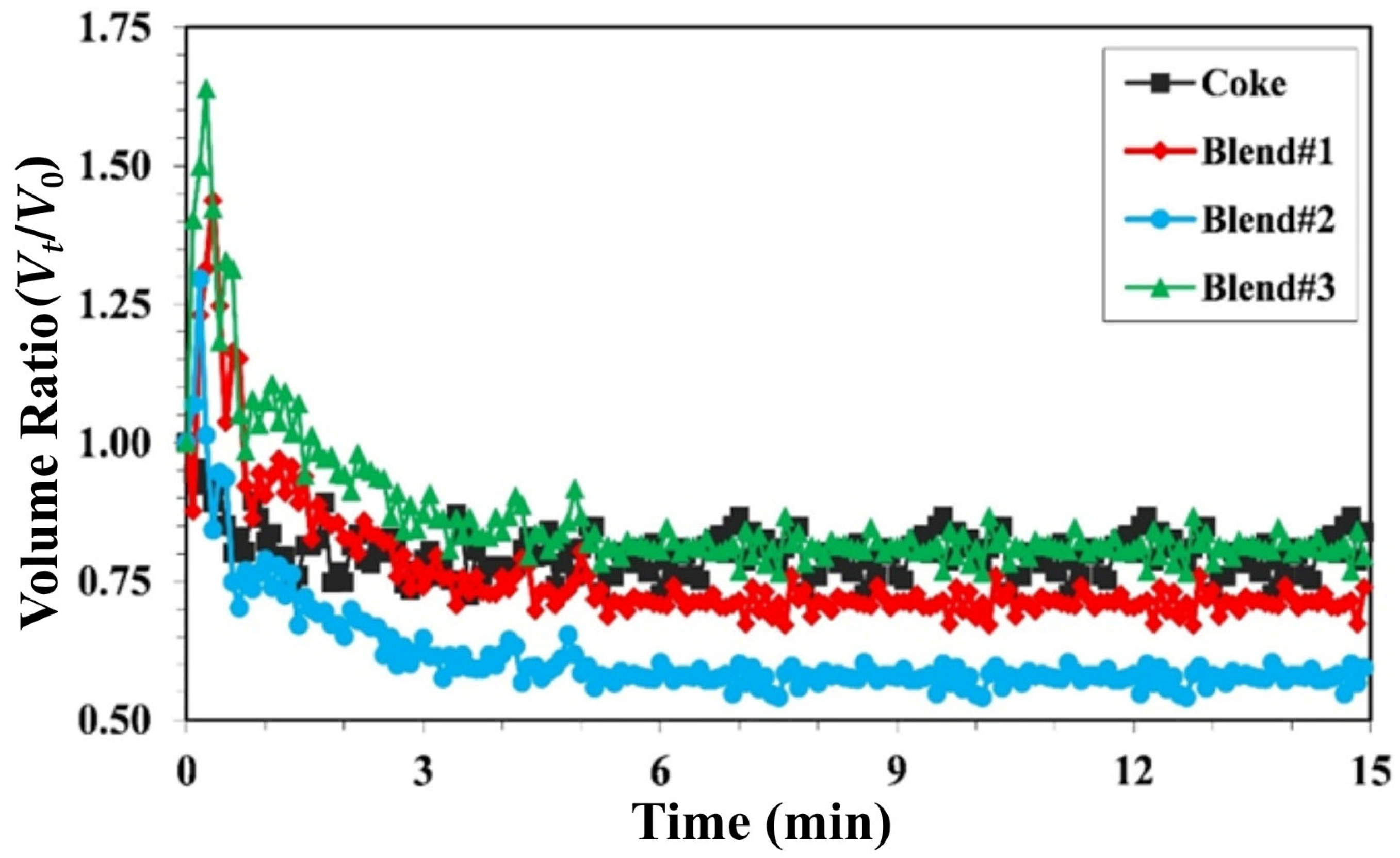
In the present study, slag foaming behavior was characterized by the ratio of the slag droplet volume at time t (Vₜ) to its initial volume at t = 0 (V0). Figure 2 presents the relationship between the volume ratio (Vt/V0) and reaction time. The coke sample exhibited minimal volume change, with Vt/V0 remaining below 1.0 initially and stabilizing at ~0.85. In contrast, the blended samples (Blend#1–Blend#3) showed a rapid expansion within the first minute, followed by a gradual decrease and stabilization after approximately 2 min. Blend#1 displayed a pronounced initial expansion, reaching a maximum Vt/V0 of ~1.45 before stabilizing at ~0.8, indicating temporary slag foaming caused by CO/CO2 evolution from FeO reduction and volatile release from Bakelite. Blend#2 exhibited a smaller initial expansion (Vt/V0 ≈ 1.3) and subsequently decreased to ~0.65, signifying significant foam collapse. Blend#3 showed the greatest expansion, reaching a peak Vt/V0 of ~1.7 and remaining above 1.0 for nearly two minutes. Overall, coke produced limited but stable foaming, while the Bakelite-containing blends exhibited greater expansion and contraction depending on the Bakelite content. The slag foaming tendency followed the order Blend#3 > Blend#1 > Blend#2 > coke, reflecting differences in carbon characteristics and gas retention capacity. Slag foaming originates from gas generation, primarily CO and CO2, produced via the FeO–C reaction in the molten slag and the Boudouard reaction (C + CO2 → 2CO) [19,20,21,22,23,24]. Although Blend#3 reaches a high initial foaming peak, its most significant feature is the sustained foam stability over time. This suggests that the generated gas is effectively retained within the slag rather than escaping rapidly. In contrast, the poor foam stability of Blend#2 may indicate inefficient gas retention, leading to rapid gas escape and reduced reaction efficiency [19,24]. Therefore, the FeO reduction behavior of metallurgical coke and its Bakelite blends, along with gas evolution, will be examined in the subsequent section.

2.2. Reduction of Iron Oxides in Slag

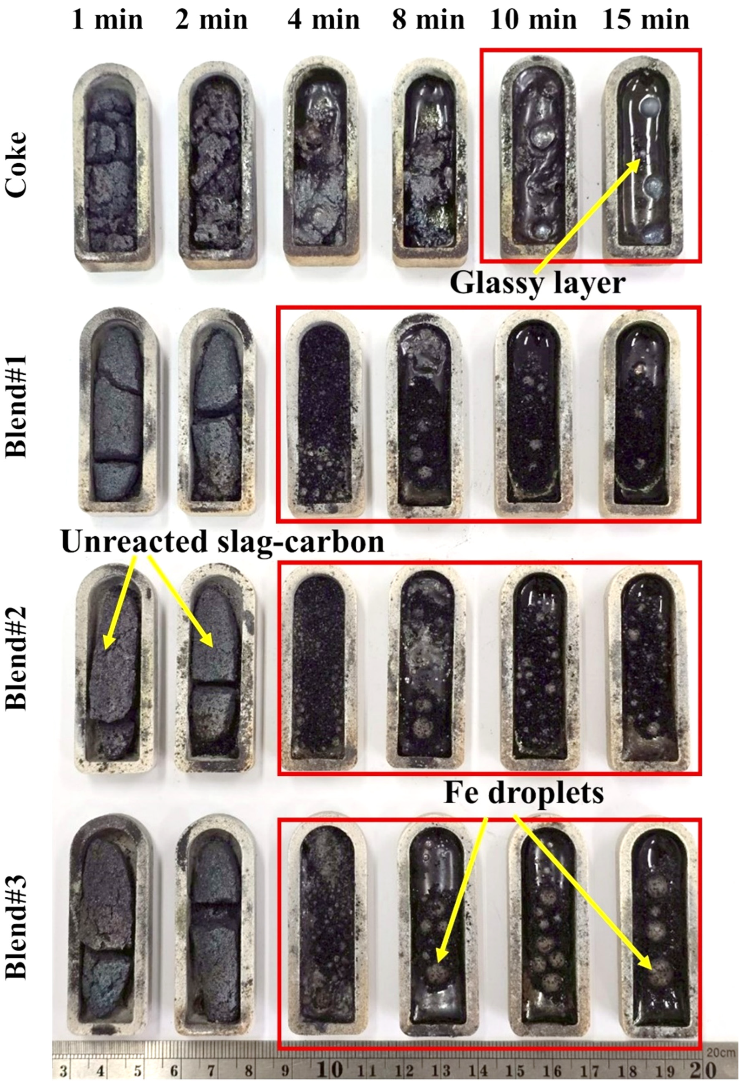
Carbon plays an essential role in steelmaking by reducing FeO to metallic Fe, generating CO/CO2 gases that become entrapped within the slag and promote slag foaming–an important phenomenon during melting. Figure 3 presents the carbon–slag pellets (CSPs) after heating at 1550 °C for 15 min for the coke, Blend#1, Blend#2, and Blend#3 samples. For coke, negligible reaction was observed during the first 1–8 min, and the pellet retained its initial solid morphology. After approximately 10 min, partial melting and the formation of a glassy surface layer were detected, accompanied by limited FeO reduction, as evidenced by a few large but sparsely distributed Fe droplets. In Blend#1, which contained Bakelite-derived carbon, the onset of reaction occurred earlier. Partial slag melting was observed at 4–8 min, although substantial unreacted slag–carbon regions remained. Small Fe droplets appeared from 4 min onward, indicating a faster FeO reduction rate compared with coke, although the extent of reduction remained incomplete at this stage. For Blend#2, FeO reduction was more pronounced. From 4 min onward, liquid–slag separation and numerous fine Fe droplets were observed, suggesting a greater reduction extent relative to coke and Blend#1. Blend#3, containing the highest Bakelite content, exhibited the most rapid and efficient reduction behavior. Fe droplets formed abundantly from 4 min onward and progressively coalesced into larger droplets by 15 min, clearly separating from the residual slag and glassy phase. This blend produced the highest amount of reduced Fe among all samples. Overall, increasing the proportion of Bakelite in the carbon blend trended to accelerate and enhance FeO reduction. This improvement might be attributed to the differences in characteristics of Bakelite carbon, which could promote reduction and result in greater metal droplet formation and larger Fe yields.
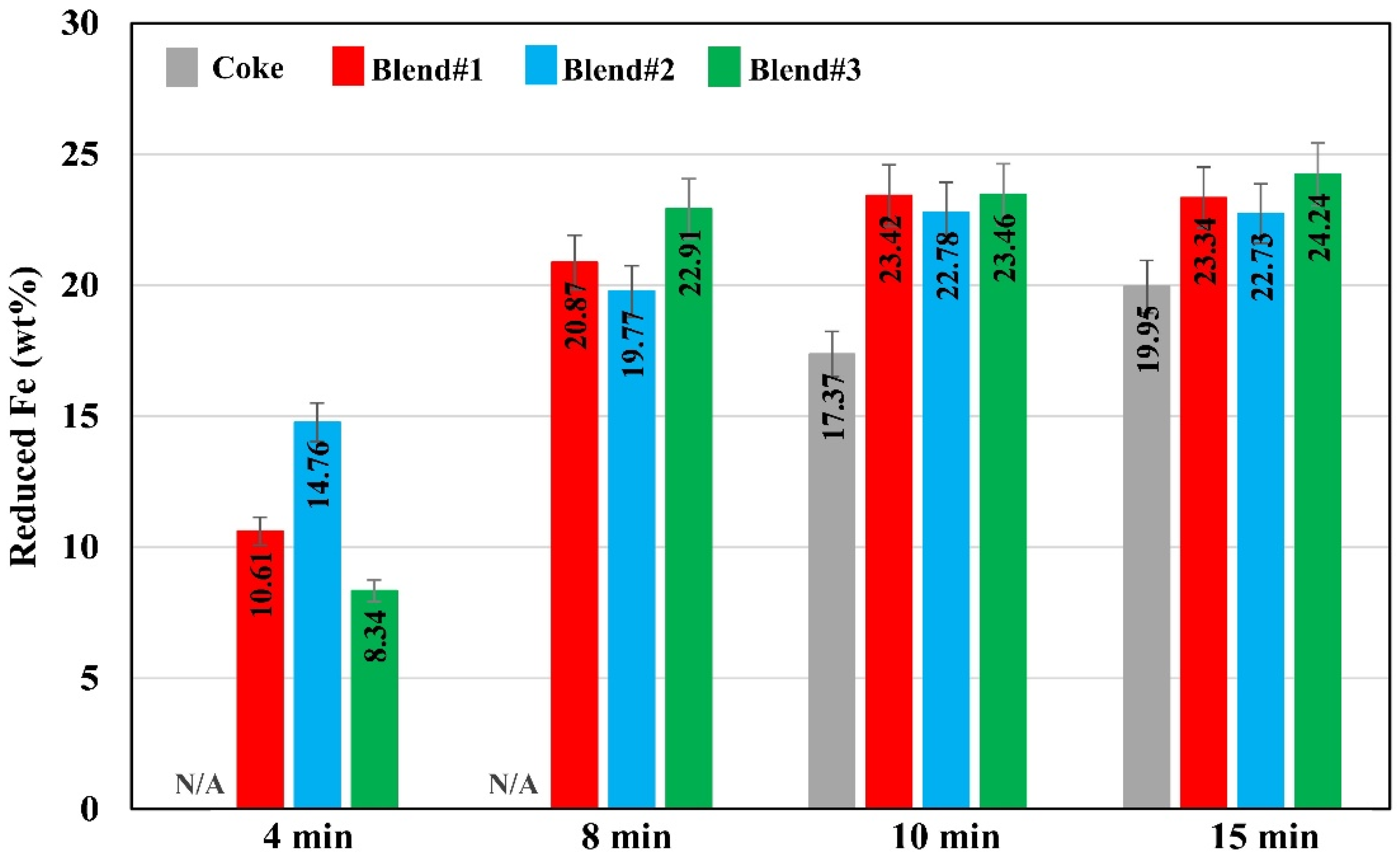
The reduced iron droplets were collected from the crucibles and washed with ethanol to remove any debris adhering to their surfaces. Figure 4 shows the amount of reduced iron (wt%) obtained after heating the slag–carbon pellets (CSP) at 1550 °C for coke, Blend#1, Blend#2, and Blend#3. The results indicate that the reduced Fe content increased with heating time for all samples, with clear differences in reduction efficiency depending on the type of reductant. At 4 min, no measurable Fe droplets were detected for coke due to the absence of significant reaction. In contrast, Blend#1, Blend#2, and Blend#3 had already initiated reduction, yielding 10.61, 14.76, and 8.34 wt% Fe, respectively. At 8 min, the reduced Fe content increased markedly in all blends, particularly in Blend#3 (22.91 wt%), which exhibited the highest value, followed by Blend#1 (20.87 wt%) and Blend#2 (19.77 wt%). Coke still showed negligible reduction at this stage. At 10 min, all four samples produced comparable Fe contents (17.37–23.46 wt%), with Blend#1 and Blend#3 reaching the highest levels (≈23.4 wt%), indicating more complete FeO reduction. At 15 min, the reduced Fe content approached a steady state. Blend#3 remained the most efficient (24.24 wt%), followed by Blend#1 (23.34 wt%), Blend#2 (22.73 wt%), and coke (19.95 wt%). Overall, incorporating Bakelite-derived carbon markedly enhanced FeO reduction compared with coke alone. Blend#3, containing the highest Bakelite fraction, exhibited the fastest reduction rate and the greatest Fe yield at 15 min.
Using the amount of metallic iron obtained, the degree of metallization (DOM) of iron oxides in the slag was calculated, and the results are summarized in Table 1. After heating the slag–carbon pellets at 1550 °C for 15 min, clear differences in DOM were observed among the carbon sources. Coke alone produced a DOM of 77.30%, whereas Blend#1, Blend#2, and Blend#3 yielded 81.65%, 80.56%, and 84.41%, respectively. These results demonstrate that incorporating Bakelite-derived carbon trends to enhance the FeO-to-Fe reduction efficiency, with Blend#3 showing the highest degree of metallization.
In slag foaming practice, oxygen was injected into the molten steel layer, which promotes the oxidation of iron and the formation of FeO, subsequently incorporated into the slag, as described by Equation (1). Carbon is then injected into the slag layer floating on the molten steel surface to reduce FeO to metallic iron, as shown in Equation (2). This reaction generates CO gas within the slag phase, causing the molten slag to expand and form a stable foam. Slag foaming is also influenced by the solute carbon of the molten steel, since FeO in the slag can also react with dissolved atomic carbon, as expressed in Equation (3). Furthermore, the CO gas generated in the system can react with FeO in the slag through slag–gas interactions, producing metallic iron and CO2 gas, as shown in Equation (4). The CO2 generated can subsequently react with injected carbon to regenerate CO via the Boudouard reaction, as described in Equation (5). In the present study, the formation of metallic iron is confirmed in Figure 3, while gas-phase products are quantified and discussed in the following section. These reactions are thermodynamically feasible at steelmaking temperatures (≥1550 °C) [19,20].
Fe(l) + 1/2O2(g) = FeO(slag)
FeO(l) + C(s) = Fe(l) + CO(g)
FeO(l) + [C] = Fe(l) + CO(g)
FeO(l) + CO(g) = Fe(l) + CO2(g)
C(s) + CO2(g) = 2CO(g)

2.3. Gas Evolution During the Reduction of Iron Oxides

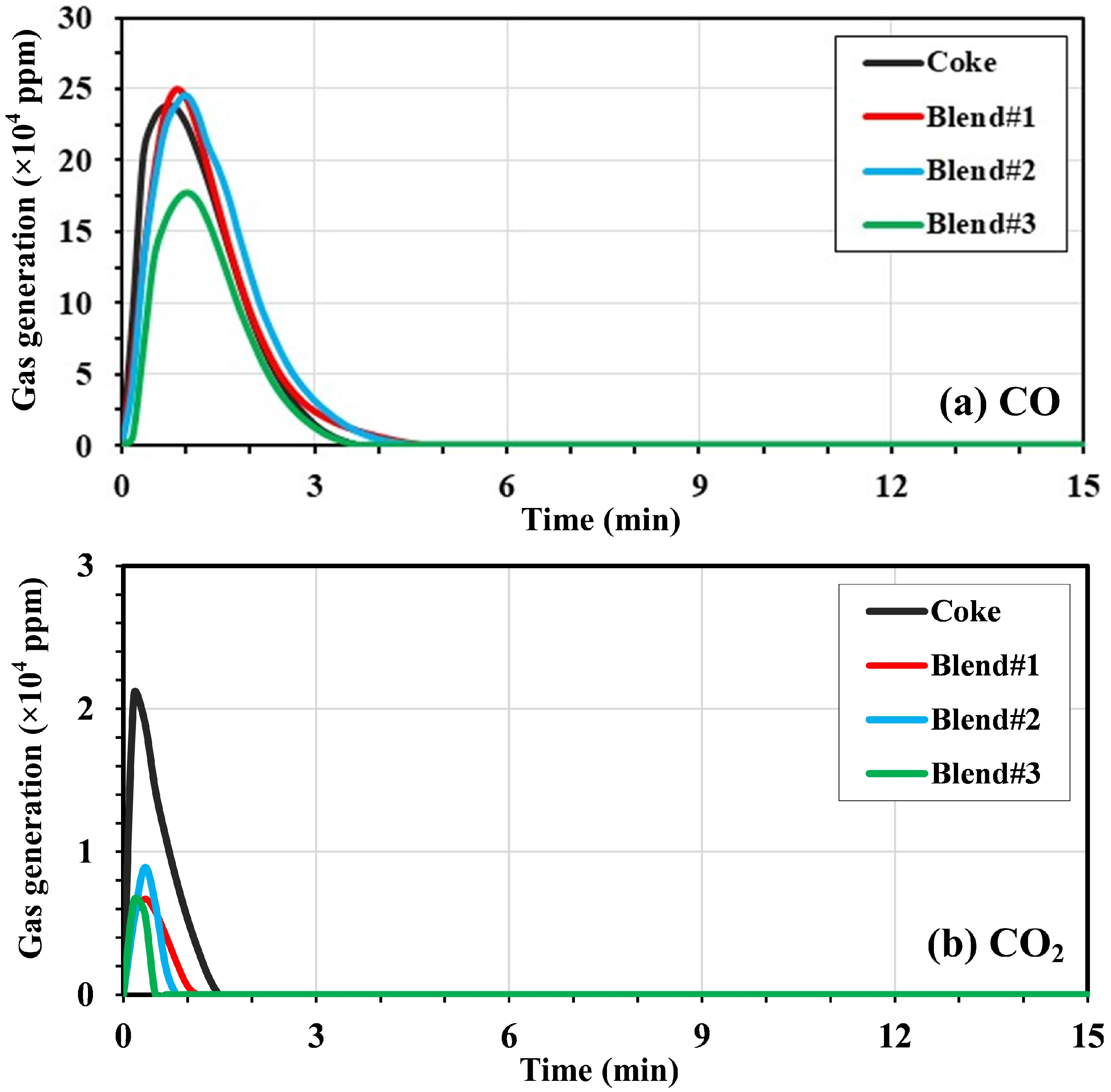
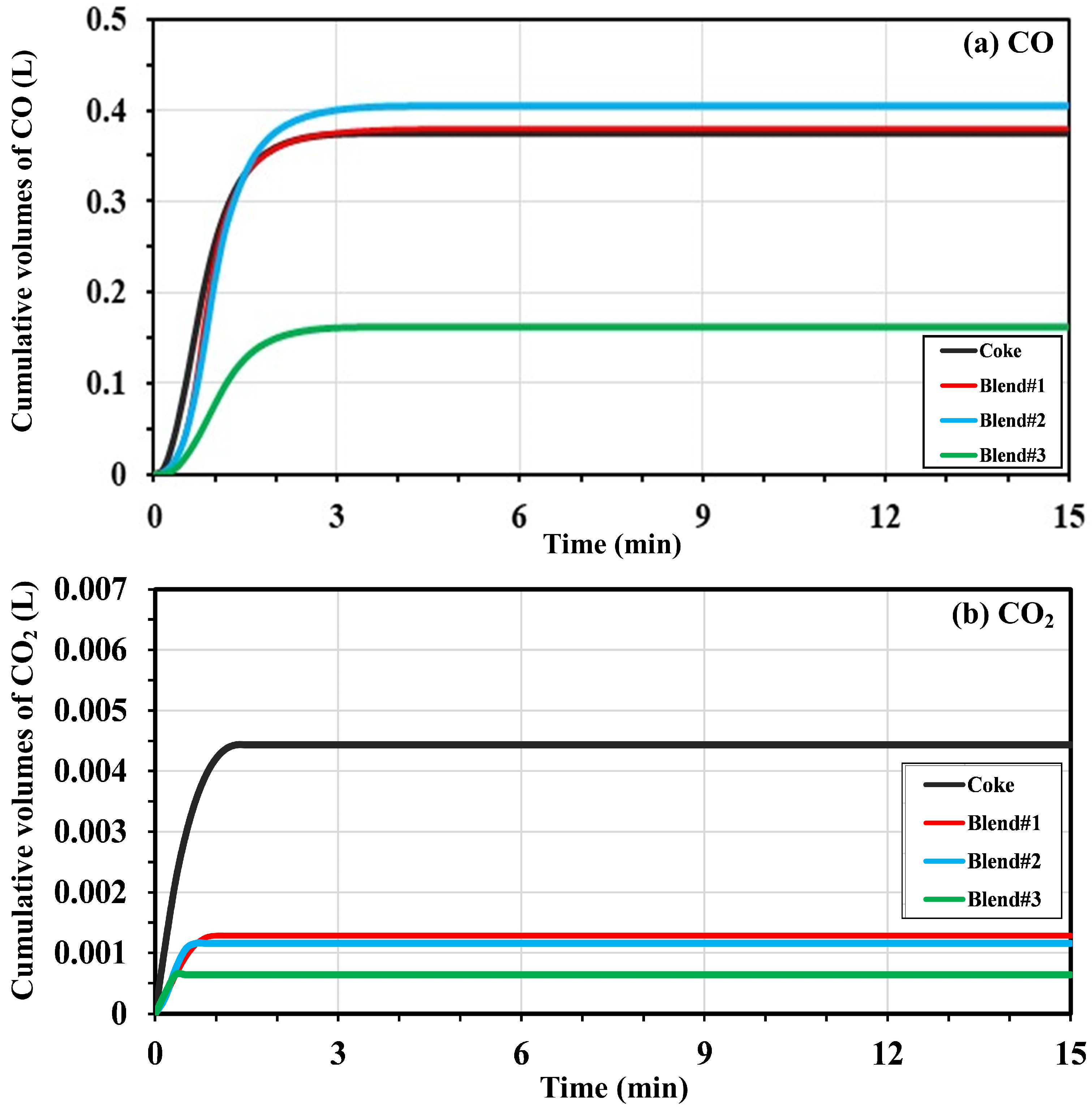
Figure 5 shows the evolution of CO and CO2 during the reduction of iron oxides in slag–carbon pellets heated at 1550 °C for coke, Blend#1, Blend#2, and Blend#3. Gas analysis using an IR analyzer indicates that CO is the dominant species, primarily generated within the first 5 min, whereas CO2 is present in lower amounts and mainly evolves within the first 2 min. These gases originate predominantly from FeO reduction, with a minor contribution from carbon oxidation. Coke exhibits CO and CO2 concentrations of approximately 240,000 and 21,000 ppm, respectively. Blend#1 and Blend#2 show comparable CO levels (~250,000 ppm) and CO2 concentrations of 7000–8000 ppm. In contrast, Blend#3 displays significantly lower gas evolution, with CO reduced by ~30% (~180,000 ppm) and CO2 limited to ~6000 ppm. In industrial EAF operations, FeO is continuously generated through oxygen lancing, whereas in the present study, FeO was initially present in the slag and subsequently reduced. Therefore, the results represent a reduction-controlled condition, while actual EAF practice involves a dynamic balance between FeO generation and reduction.
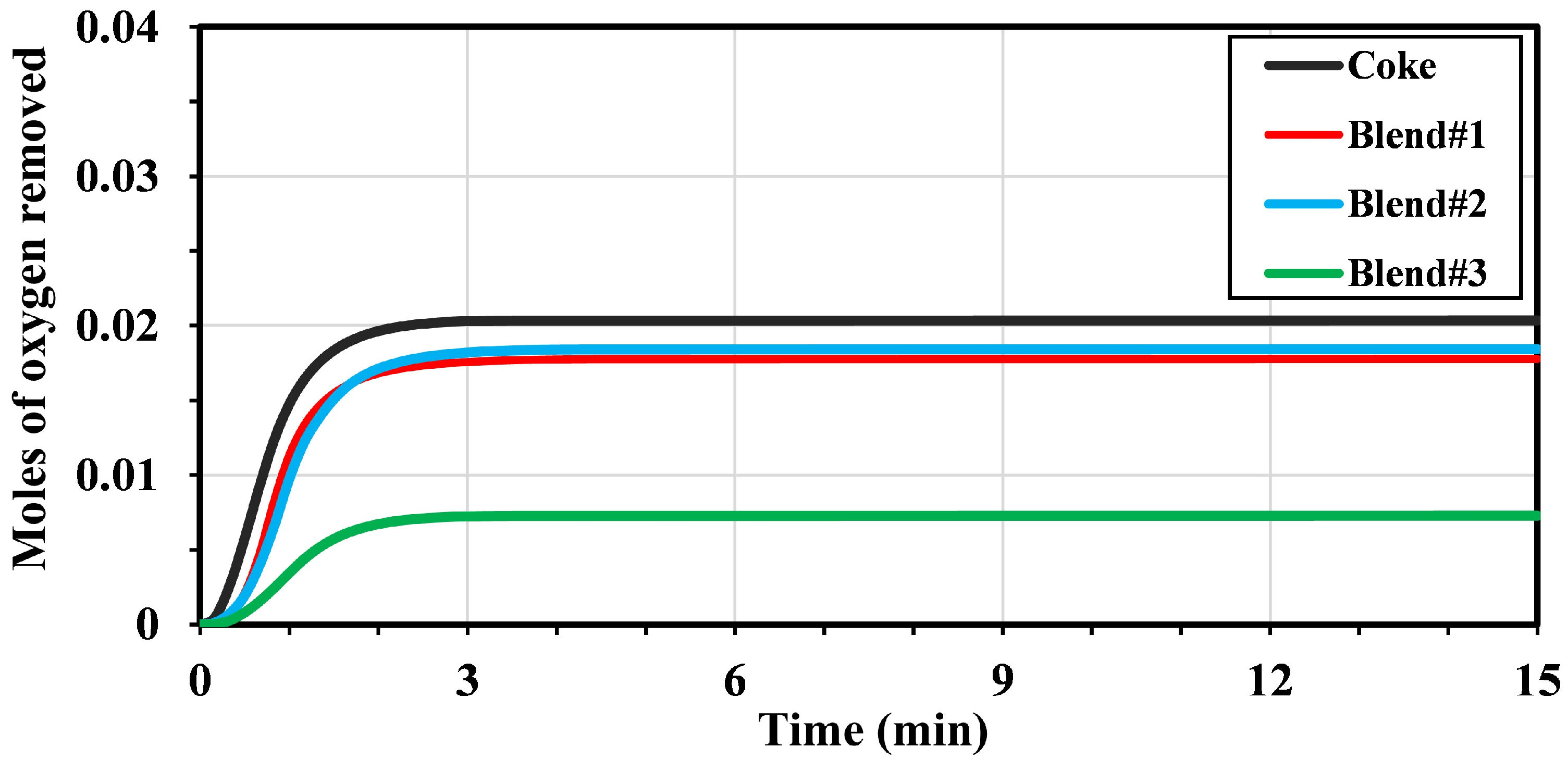
Figure 6 and Figure 7 present the cumulative gas evolution and moles of oxygen removed during heating of slag–carbon pellets at 1550 °C. The cumulative CO release for coke, Blend#1, and Blend#2 is comparable (0.37–0.40 L), whereas Blend#3 produces a significantly lower CO volume (~0.15 L). The CO2 release is substantially lower for all samples, reaching 0.0044 L for coke and ~0.0012 L for Blend#1 and Blend#2, while Blend#3 exhibits the lowest value (~0.0006 L), more than 50% lower than the others. Similarly, coke, Blend#1, and Blend#2 show comparable oxygen removal (0.018–0.020 mol), whereas Blend#3 displays a markedly lower value (~0.007 mol). Despite its lower gas evolution and oxygen removal, Blend#3 yields the highest Fe production and most pronounced slag foaming, suggesting that gas generation occurs at a controlled rate, enhancing gas retention and prolonging bubble residence time within the molten slag, thereby promoting stable slag foaming [19,24].

2.4. Factors Affecting the Slag Foaming and Iron Oxide Reduction

2.4.1. Effect of Carbon Characteristics

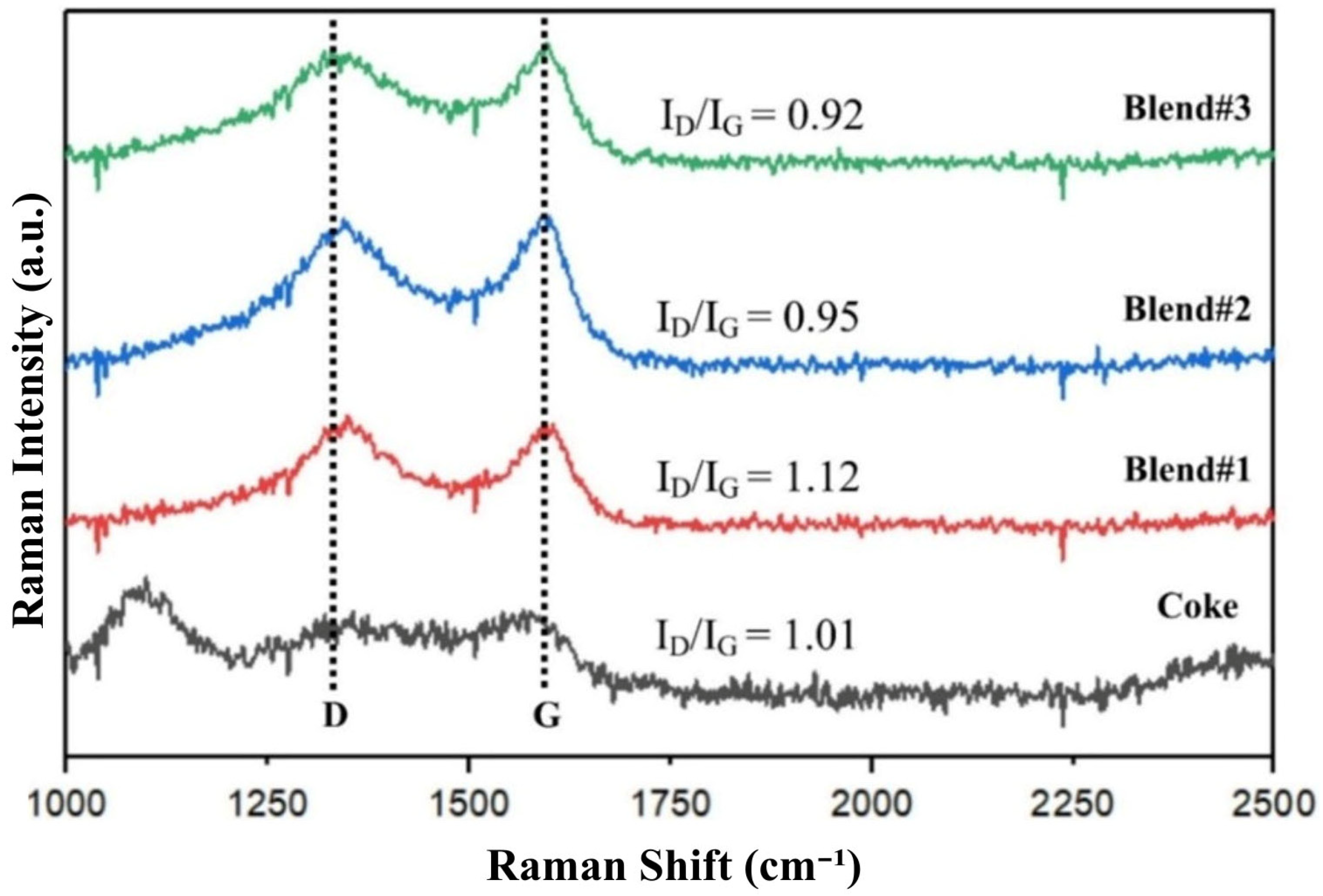
Figure 8 shows the Raman spectra of coke and Blend#1 to Blend#3. Two characteristic Raman bands are observed: the D band, located at approximately 1350 cm−1, which is associated with the amorphous or disordered carbon structure, and the G band, appearing at around 1587 cm−1, which corresponds to the graphitic (crystalline) carbon structure. The ratio of the intensities of the D and G bands (ID/IG) is commonly used to evaluate the degree of graphitization, where a lower ID/IG value indicates a higher crystalline order. As shown in Figure 8, the ID/IG ratios of all four samples fall within a narrow range of 0.92–1.12, indicating comparable carbon structures. The incorporation of Bakelite into coke slightly enhances the crystallinity of the carbon materials. Among the samples, Blend#3 exhibits the highest degree of crystallinity, with the lowest ID/IG ratio of 0.92. This enhancement can be attributed to the thermal decomposition of Bakelite during pyrolysis, resulting in the formation of CH4 and other volatile species. The CH4 may subsequently decompose into graphitic carbon and hydrogen within the system [33]. However, the evolution of hydrocarbon gas species could not be detected due to the limitations of the IR gas analyzer used in this study.
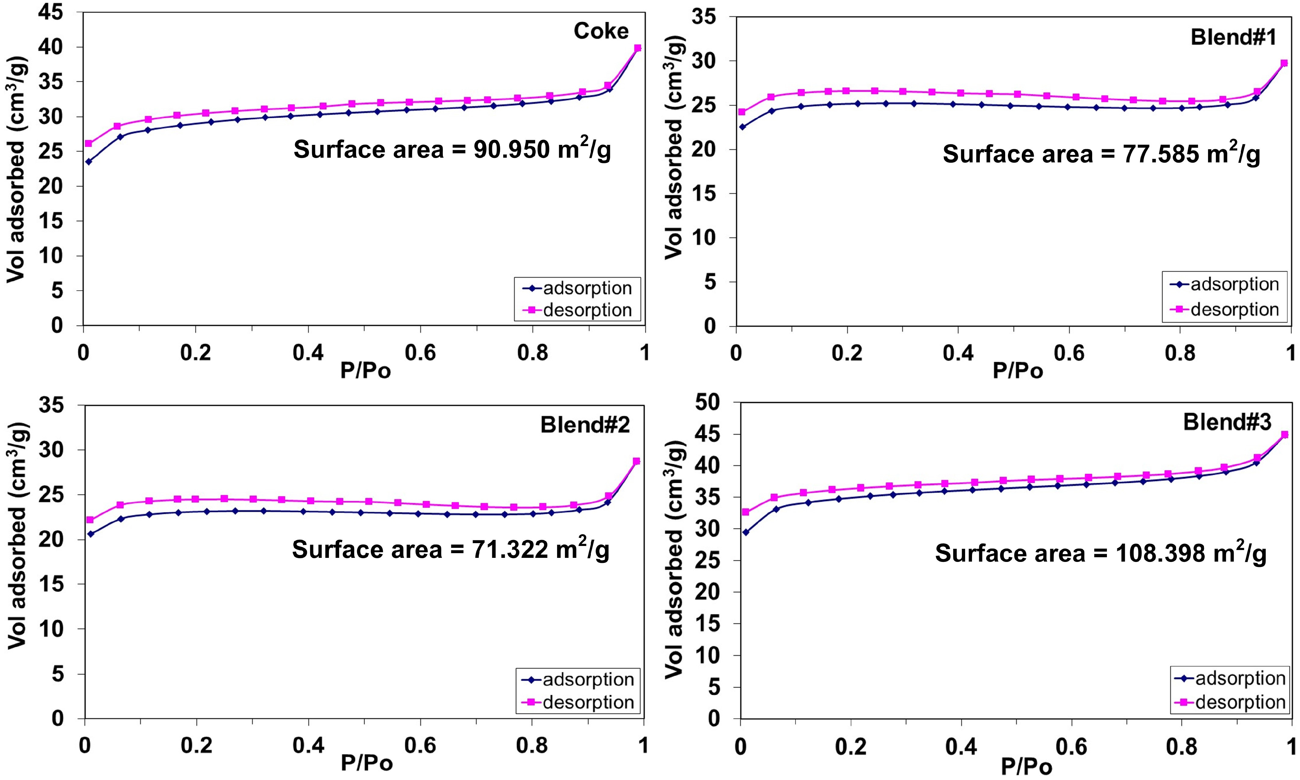
Figure 9 shows the BET surface area analysis of coke and Blend#1 to Blend#3. The coke sample shows a relatively high adsorption capacity with a BET surface area of 90.950 m2/g, indicating a well-developed pore network. In contrast, Blend#1 and Blend#2 show reduced adsorption capacities and lower surface areas of 77.585 and 71.322 m2/g, respectively, suggesting partial pore blockage or less developed porosity, as reflected by the flatter adsorption profiles in the intermediate relative pressure range (P/P0 ≈ 0.2–0.8). Notably, Blend#3 shows the highest adsorption capacity and surface area (108.398 m2/g), with a steeper uptake at low P/P0 and a more pronounced hysteresis loop, indicating enhanced micro–mesoporous structure and improved pore connectivity. Overall, the results suggest that increasing Bakelite content initially reduces porosity (Blend#1–Blend#2), but at higher addition (Blend#3), significantly enhances pore development, likely due to increased volatile release and pore formation during thermal treatment at 1000 °C.
The reduction of iron oxides proceeds sequentially (Fe2O3 → Fe3O4 → FeO → Fe), with the FeO → Fe step being significantly slower than the preceding stages. Otsuka and Kunii [34] reported that this step is markedly enhanced when graphite is used as a reductant, due to the catalytic effect of metallic iron on carbon gasification. The rate of gas generation significantly influences slag foaming and depends on the characteristics of the carbonaceous material. Rahman et al. [19] examined the interaction of EAF slag with metallurgical coke and natural graphite at 1550 °C using the sessile drop technique. Gas evolution (CO and CO2) was notably higher for coke than for graphite, indicating rapid FeO reduction by coke. Despite the high gas generation, poor bubble retention occurred in the slag due to rapid escape of gas. High gas generation also promoted convective transport across the slag–coke interface, partially dissolving ash oxides and altering slag composition [19]. In contrast, natural graphite exhibited slower gas generation and FeO reduction but facilitated efficient bubble entrapment, resulting in enhanced slag foaming [19]. Kongkarat et al. [24] studied interactions between EAF slag and metallurgical coke, as well as blends with waste polyethylene terephthalate (PET) and polyurethane (PU). Both the PET/coke and PU/coke blends exhibited slower gas generation (CO and CO2) compared to pure coke, but enhanced bubble retention in the slag. As PET and PU are polymeric and free of ash oxides, the slower gas evolution reduced slag composition changes and allowed more bubbles to remain trapped, resulting in improved slag foaming relative to coke alone [24].
The greater extent of FeO reduction and improved slag foaming behavior of Blend#3, despite its lower CO/CO2 emission, is attributed to its optimized pore structure and enhanced gas utilization efficiency. Its higher surface area and well-developed micro–mesoporous connectivity promote effective FeO–C interfacial contact, thereby accelerating the reduction reaction. The interconnected pore network also facilitates the retention of internally generated gases (CO and CO2), enabling their participation in the Boudouard reaction and promoting in situ CO regeneration rather than direct gas escape [19,20,21,22,23,24], which contributes to sustained slag foaming with reduced off-gas emission. Despite exhibiting the lowest cumulative gas evolution, Blend#3 achieves the highest degree of FeO reduction, indicating that CO and CO2 release alone is not a reliable indicator of reduction efficiency. Raman analysis reveals a lower ID/IG ratio, corresponding to a more ordered carbon structure that suppresses gasification while enhancing carbon stability and prolonging slag–carbon interaction, thereby promoting direct FeO–C reduction [34]. Furthermore, carbon derived from Bakelite decomposition may improve slag wettability, increasing CO residence time within the slag. Collectively, these factors result in more efficient FeO reduction and stable slag foaming, even with lower apparent CO/CO2 evolution.

2.4.2. Effect of Filler Impurities (CaO)

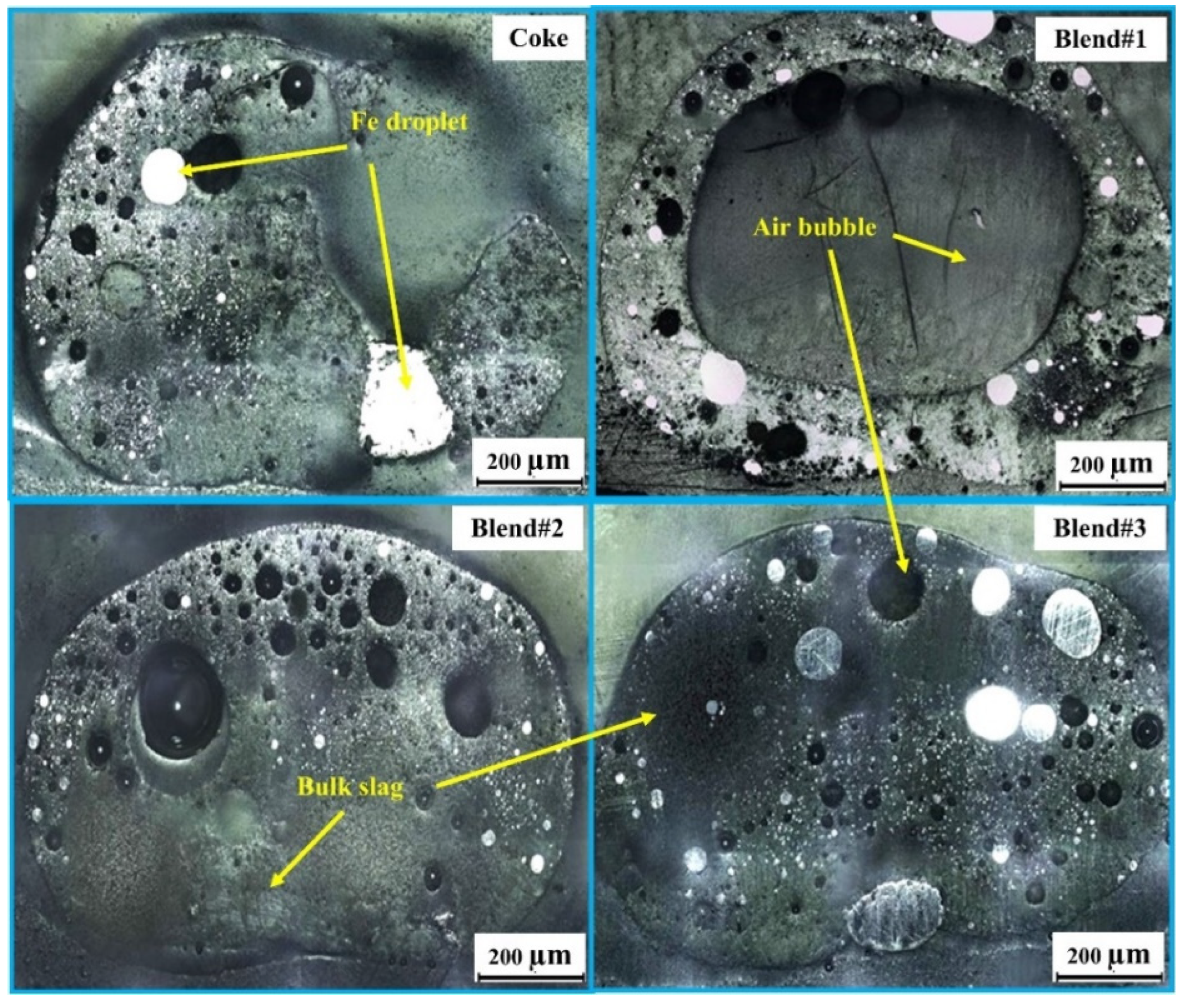
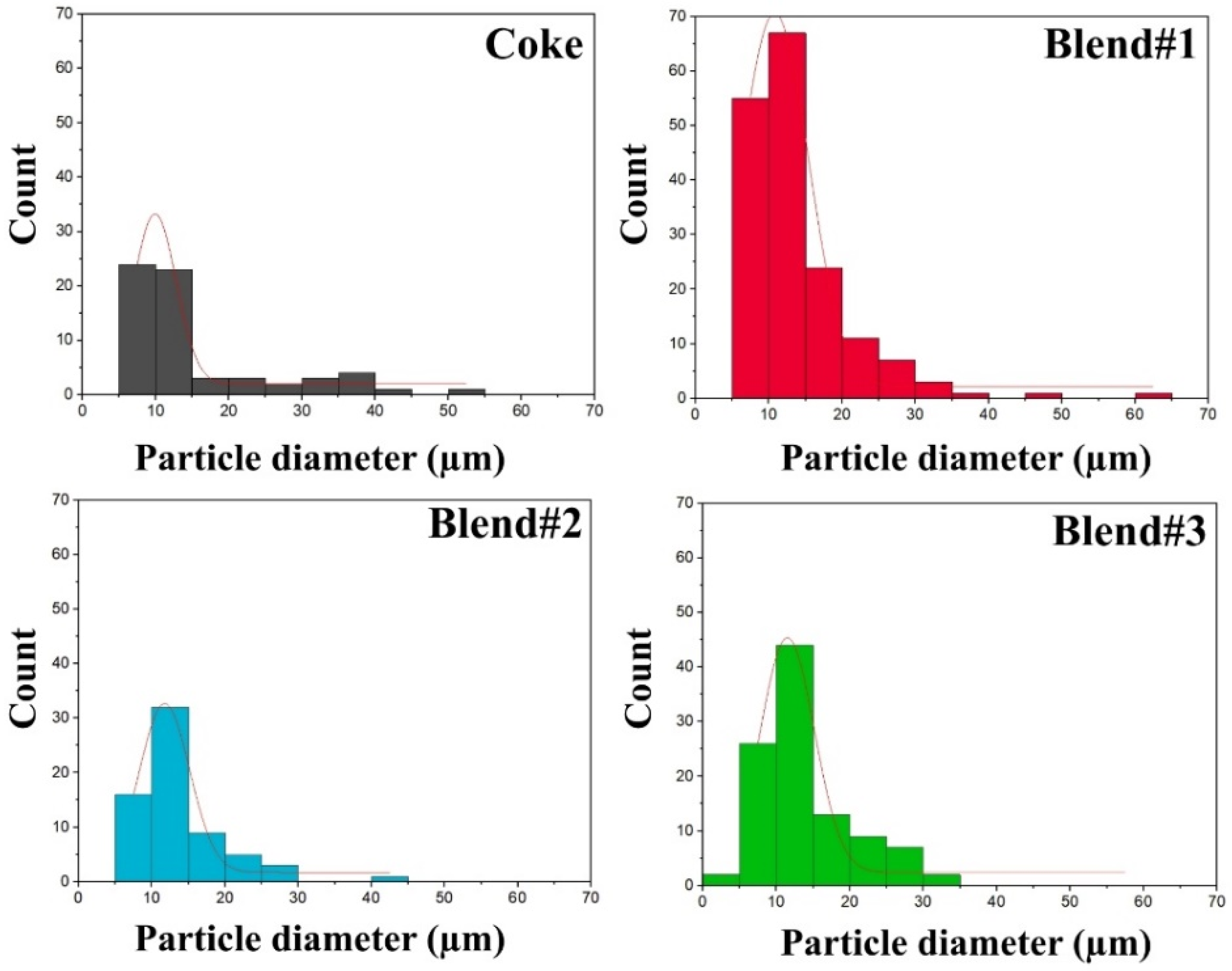
The extent of slag foaming was strongly dependent on characteristics of the carbon and was primarily controlled by FeO reduction by carbon, as well as interfacial phenomena induced by ash oxides that modified the slag’s physicochemical properties, including viscosity, density, and surface tension [4,5]. These changes directly influenced gas retention and slag droplet morphology. As illustrated in Figure 1, the quenched slag droplets were resin-mounted and cross-sectioned to evaluate gas entrapment behavior within the molten slag. Figure 10 presents cross-sectional images of slag droplets reacted with coke, Blend#1, Blend#2, and Blend#3 at 1550 °C for 15 min, enabling comparison of gas bubble morphology and the distribution of reduced Fe particles. Figure 11 shows the corresponding gas bubble size distributions in the slag droplets under the same conditions, quantified from optical micrographs of cross-sectioned samples using the image analysis software ImageJ2 (version 2.14.0/1.54f). The presence of gas bubbles indicates the slag’s ability to retain gas, which contributes to slag foaming. Small, uniformly distributed bubbles enhance foam stability, whereas large and unevenly distributed bubbles lead to unstable foaming with greater fluctuation [8,9]. This heterogeneous bubble structure indicates enhanced gas retention and prolonged gas–slag interaction, consistent with improved slag foaming behavior and higher reduction efficiency.
Distinct differences in bubble morphology were observed among the samples. The coke sample exhibited well-defined metallic Fe particles accompanied by fine, uniformly distributed gas bubbles. The bubble size distribution was narrow and dominated by small bubbles, primarily below ~15 μm, with only a limited number of larger bubbles (~30–50 μm). In contrast, Blend#1 exhibited large gas bubbles occupying a substantial fraction of the droplet volume and a broad, right-skewed bubble size distribution extending beyond ~30–60 μm. For Blend#2, medium-to-small gas bubbles were predominantly concentrated near the droplet surface, while the core region consisted of dense bulk slag with relatively few bubbles. The bubble size distribution was intermediate, with most bubbles in the small-to-medium range (~10–20 μm) and fewer large bubbles than in Blend#1 (~30–40 μm). Blend#3 exhibited a wide bubble size distribution throughout the slag matrix, with the highest population of small and medium-sized bubbles of ~5–30 μm among all samples. This morphology indicates vigorous FeO reduction and significant gas evolution, accompanied by enhanced gas retention in the molten slag. Consequently, the slag reacted with Blend#3 showed strong and sustained foaming behavior throughout the melting period.
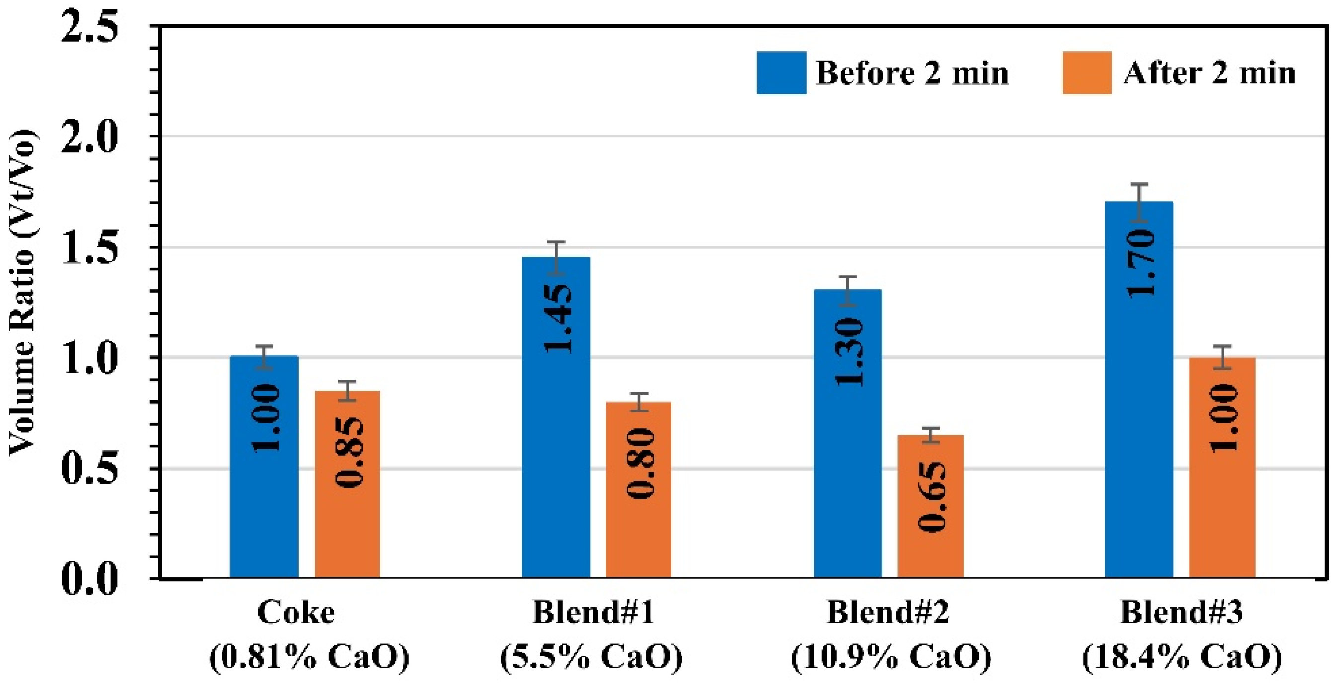
Figure 12 compares the normalized slag volume ratio (Vt/V0) measured before and after 2 min for coke and the three blended carbon systems with increasing CaO content. Before 2 min, the slag volume increased for all blends relative to coke, with Vt/V0 values of 1.45 for Blend#1, 1.30 for Blend#2, and the highest expansion of 1.70 for Blend#3, compared with 1.00 for coke. After 2 min, a volume decrease was observed for all samples, indicating partial collapse of the foamed slag. Coke showed a modest reduction to 0.85, while Blend#1 and Blend#2 exhibited more pronounced shrinkage to 0.80 and 0.65, respectively. In contrast, Blend#3 retained a higher slag volume after 2 min (Vt/V0 ≈ 1.00), suggesting improved foam stability and gas retention compared with the other systems. Overall, the data indicate that higher-CaO-containing blends, particularly Blend#3, promote greater initial slag expansion and enhanced foam stability over time.
The higher CaO content in Blend#3, resulting from its greater Bakelite fraction, likely alters the slag composition and its physical properties, particularly viscosity, thereby enhancing CO retention and suppressing bubble escape. This could be one of the factors prolonging bubble residence time, contributing to more stable slag foaming [8,9]. However, due to the limitations of the sessile drop technique employed in this study, the physical properties of the slag droplet could not be directly determined. Moreover, the added CaO is beneficial for steelmaking, as lime (CaO) is routinely added during refining; thus, substituting part of the coke with Bakelite could help reduce lime consumption and overall production costs. Given that Blend#3 exhibits the lowest CO emissions while providing superior slag foaming and the highest FeO reduction efficiency, it represents a promising alternative to conventional carbon sources such as coke, offering reduced carbon emissions and lower fossil fuel consumption.

3. Materials and Methods

3.1. Materials

EAF slag was obtained from UMC Metal Co., Ltd., a steelmaking plant located in Chonburi, Thailand. The slag was ground and sieved to obtain particles smaller than 180 µm. The chemical composition, determined by X-ray fluorescence (XRF, Model ZSX Primus, Rigaku, Japan), is presented in Table 2. Iron oxide (Fe2O3) was identified as the major constituent, accounting for 34.48 wt% (equivalent to 30.69 wt% FeO). The basicity index (B3) of the slag was calculated to be 1.1.
The metallurgical coke sample was supplied by UMC Metal Co., Ltd., while Bakelite waste was collected from GD Plastics, a recycling facility in Phra Samut Chedi District, Samut Prakan Province, Thailand. Bakelite is a thermoset polymer composed primarily of carbon (56.2 wt%), along with hydrogen (4.3 wt%), oxygen (11.4 wt%), and sulfur (0.01 wt%). It also contains approximately 31.32 wt% calcium carbonate (CaCO3) as a filler. Both Bakelite and metallurgical coke were ground using a ball mill and sieved to obtain particles smaller than 180 µm. The powders were then blended at three different coke-to-Bakelite ratios using a rolling mill, designated as Blend#1–Blend#3. Each mixture was heat-treated at 1000 °C for 1 h in a horizontal tube furnace under an argon atmosphere (flow rate: 1 L/min) to produce carbonaceous chars. The blend ratios and compositions of the resulting chars are summarized in Table 3 using a LECO CHN628 analyzer. LECO is the commercial company for the chemical analyzer, LECO Corporation, St. Joseph, MI, USA. The oxide composition of the ash residues was analyzed by XRF, as shown in Table 4. The major oxides present were SiO2, Al2O3, Fe2O3, and CaO. The presence of CaO is attributed to the thermal decomposition of the CaCO3 filler during heat treatment, with CaO content increasing proportionally with Bakelite concentration in the blends. The surface area of the char samples was determined using the Brunauer–Emmett–Teller (BET) method with a Micromeritics 3Flex surface characterization analyzer, Norcross, GA, USA.

3.2. Experimental

3.2.1. Slag Foaming

Approximately 1 g of carbon-blend powder was pressed into ~2 cm diameter pellets and dried at 90 °C for 48 h to remove moisture. Each pellet was placed on a sample holder, and ~0.3 g of slag powder was added to its center. The assemblies were heated at 1550 °C for 15 min in a horizontal tube furnace under an argon atmosphere (flow rate: 1 L/min), with the reaction recorded by video. Slag droplets, initially spherical, were captured every 5 s, and their volumes (V) were determined using image analysis. Minor deviations from an ideal spherical shape were ignored (estimated error < 5%). Quantitative assessment of slag foaming behavior for the four carbon samples can be enabled via the calculation of Vt/V0 ratios using ImageJ2 (version 2.14.0/1.54f). Vt represents the volume of the slag droplet at time t, whereas V0 denotes its initial volume at t = 0. The program extracted selected frames for analysis and stored the computed data in output files. Details of the software are reported elsewhere [19,24].

3.2.2. FeO Reduction

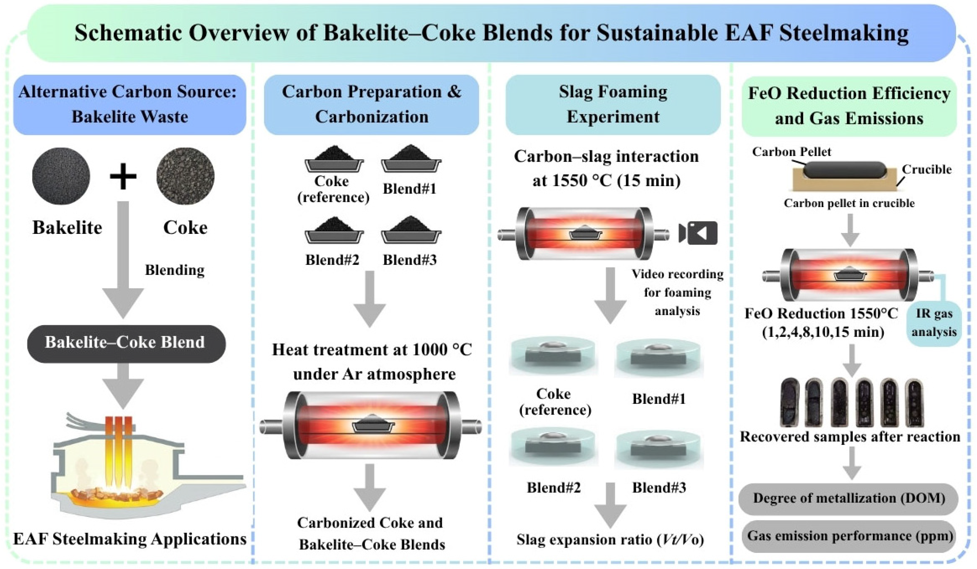
To assess the potential of the carbon samples for steelmaking applications, four types of carbon samples were mixed with slag powder according to Table 5. To produce carbon–slag pellets (CSPs), the mixtures were moistened with water, hand-shaped into ~10 g pellets, and dried at 90 °C for 48 h. The dried pellets were then heated at 1550 °C, and quenched at 1, 2, 4, 8, 10, and 15 min in a horizontal tube furnace under an argon atmosphere. The FeO reduction behavior was monitored by measuring CO and CO2 evolution with an IR gas analyzer (Model IR202, Yokogawa, Tokyo, Japan). The metallic iron produced was subsequently analyzed to determine the degree of metallization. Sample preparation and an experimental overview of this study are shown in Figure 13.

4. Conclusions

This study evaluated the feasibility of utilizing waste Bakelite thermoset blended with metallurgical coke as an alternative carbon source for FeO reduction and slag foaming in EAF steelmaking at 1550 °C. The results demonstrate that Bakelite–coke blends can effectively replace conventional coke while enhancing process performance. Incorporation of Bakelite modified the carbon structure and ash composition. Compared with coke, all blends enhanced slag foaming behavior, with Blend#3 exhibiting the highest slag expansion (Vt/V0 ≈ 1.7) and most stable foam due to the formation of uniformly distributed multi-sized gas bubbles. FeO reduction was accelerated with increasing Bakelite content, leading to earlier and more metallic iron formation, and resulting in higher degrees of metallization, reaching 84.41% for Blend#3. In addition, Blend#3 achieved the highest reduction performance despite ~30% lower gas emissions, indicating that gas retention and utilization are more important than total gas evolution. This behavior is attributed to its optimized pore structure, improved gas retention, and more ordered carbon structure, which promote effective FeO–C reactions and stable foaming. CaO present as an impurity in Bakelite may influence the slag composition and its physical properties, which could contribute to prolonged bubble residence time and improved slag foaming stability. Overall, Bakelite waste (30 wt%) shows strong potential as a sustainable carbon substitute, reducing fossil fuel use while improving process efficiency.

Author Contributions

Conceptualization, T.C. and S.K.; methodology, T.C., K.S. and S.K.; software, T.C. and S.K.; validation, T.C. and S.K.; formal analysis, T.C. and S.K.; investigation, T.C., K.S. and S.K.; resources, S.K.; data curation, T.C. and S.K.; writing—original draft preparation, T.C. and S.K.; writing—review and editing, S.K.; visualization, T.C. and S.K.; supervision, S.K.; project administration, S.K.; funding acquisition, S.K. All authors have read and agreed to the published version of the manuscript.

Funding

This study was supported by the Faculty of Science and Technology, Contract No. SciGR 23/2567.

Data Availability Statement

The original contributions presented in this study are included in the article. Further inquiries can be directed to the corresponding author.

Acknowledgments

The authors gratefully acknowledge the financial support provided by the Faculty of Science and Technology, Thammasat University, Contract No. SciGR 23/2567.

Conflicts of Interest

The authors declare no conflicts of interest.

References

  1. Echterhof, T. Review on the Use of Alternative Carbon Sources in EAF Steelmaking. Metals 2021, 11, 222. [Google Scholar] [CrossRef]
  2. Heo, J.; Park, J. Effect of Slag Composition on Dephosphorization and Foamability in the Electric Arc Furnace Steelmaking Process: Improvement of Plant Operation. Metall. Mater. Trans. B 2021, 52, 3613–3623. [Google Scholar] [CrossRef]
  3. Hara, S.; Ogino, K. Slag-foaming phenomenon in pyrometallurgical processes. ISIJ Int. 1992, 32, 81–86. [Google Scholar] [CrossRef]
  4. Ito, K.; Fruehan, R.J. Study on the Foaming of CaO-SiO2-FeO Slags. Part I: Foaming Parameters and Experimental Results. Metall. Mater. Trans. B 1989, 20, 509–514. [Google Scholar] [CrossRef]
  5. Ito, K.; Fruehan, R.J. Study on the Foaming of CaO-SiO2-FeO Slags. Part II: Dimensional analysis and foaming in iron and steelmaking processes. Metall. Mater. Trans. B 1989, 20, 515–521. [Google Scholar] [CrossRef]
  6. Kieush, L.; Schenk, J.; Koveria, A.; Hrubiak, A.; Hopfinger, H.; Zheng, H. Evaluation of Slag Foaming Behavior Using Renewable Carbon Sources in Electric Arc Furnace-Based Steel Production. Energies 2023, 16, 4673. [Google Scholar] [CrossRef]
  7. DiGiovanni, C.; Li, D.; Ng, K.W.; Huang, X. Ranking of Injection Biochar for Slag Foaming Applications in Steelmaking. Metals 2023, 13, 1003. [Google Scholar] [CrossRef]
  8. Zhang, Y.; Fruehan, R.J. Effect of the bubble size and chemical reactions on slag Foaming. Metall. Mater. Trans. B 1995, 26, 803–812. [Google Scholar] [CrossRef]
  9. Son, W.Y.; Kee, S.H.; Kang, Y. Influence of Bubble Size on the Foaming Behavior of Molten Slag Containing FeO. Metall. Mater. Trans. B 2021, 52, 2951–2959. [Google Scholar] [CrossRef]
  10. Luz, A.P.; Tomba Martinez, A.G.; López, F.; Bonadia, P.; Pandolfelli, V.C. Slag foaming practice in the steelmaking process. Ceram. Int. 2018, 44, 8727–8741. [Google Scholar] [CrossRef]
  11. Chang, W.T.; Lin, C.M.; Su, Y.L.; Li, C.C.; Chang, Y.E.; Shen, J.M.; Wu, W. Effect of FeO Content on Foaming and Viscosity Properties in FeO-CaO-SiO2-MgO-Al2O3 Slag System. Metals 2021, 11, 289. [Google Scholar] [CrossRef]
  12. Wang, G.; Zhang, J.; Wang, Y.; Tan, Y.; Li, Z.; Zhang, B.; Liu, Z. Study on the Bath Smelting Reduction Reaction and Mechanism of Iron Ore: A Review. Metals 2023, 13, 672. [Google Scholar] [CrossRef]
  13. Worldsteel Association. Sustainability Indicators 2023 Report; Worldsteel Association: Brussels, Belgium, 2023; Available online: https://worldsteel.org/media/press-releases/2023/sustainability-indicators-2023/ (accessed on 31 January 2026).
  14. Kim, Y.; Tanaka, K.; Matsuoka, S. Environmental and economic effectiveness of the Kyoto Protocol. PLoS ONE 2020, 15, e0236299. [Google Scholar] [CrossRef]
  15. World Economic Forum. Net-Zero Industry Tracker 2024; World Economic Forum: Davos, Switzerland, 2024; Available online: https://www.weforum.org/publications/net-zero-industry-tracker-2024/steel-net-zero-tracker-2024/ (accessed on 31 January 2026).
  16. Kongkarat, S.; Khanna, R.; Koshy, P.; O’Kane, P.; Sahajwalla, V. Interactions of Polymer/Coke Blends with Molten Steel at 1823K: Interfacial Phenomena. Steel Res. Int. 2013, 84, 362–369. [Google Scholar] [CrossRef]
  17. Kongkarat, S.; Cherdhirunkorn, B.; Thongreang, R. Utilization of Waste HDPE for Sustainable EAF Steelmaking: Carbon Dissolution into Liquid Steel. Steel Res. Int. 2017, 88, 1600168. [Google Scholar] [CrossRef]
  18. Nath, D.C.; Mansuri, I.A.; Zaharia, M.; Saha-Chaudhury, N.; Sahajwalla, V. Recycling of end-of-life melamine at 1600 °C for carbon dissolution into liquid iron. ISIJ Int. 2012, 52, 922–927. [Google Scholar] [CrossRef]
  19. Rahman, M.; Khanna, R.; Sahajwalla, V.; O’Kane, P. The Influence of Ash Impurities on Interfacial Reactions between Carbonaceous Materials and EAF Slag at 1550 °C. ISIJ Int. 2009, 49, 329–336. [Google Scholar] [CrossRef]
  20. Sahajwalla, V.; Rahman, M.; Khanna, R.; Saha-Chaudhury, N.; O’Kane, P.; Skidmore, C.; Knights, D. Recycling waste plastics in EAF steelmaking: Carbon/slag interactions of HDPE-Coke blends. Steel Res. Int. 2009, 80, 535–543. [Google Scholar]
  21. Zaharia, M.; Sahajwalla, V.; Khanna, R.; Koshy, P.; O’Kane, P. Carbon/slag interactions between coke/rubber blends and EAF slag at 1550 °C. ISIJ Int. 2009, 49, 1513–1521. [Google Scholar] [CrossRef]
  22. Dankwah, J.R.; Koshy, P.; Saha-Chaudhury, N.; O’Kane, P.; Skidmore, C.; Knights, D.; Sahajwalla, V. Reduction of FeO in EAF steelmaking slag by metallurgical coke and waste plastics blends. ISIJ Int. 2011, 51, 498–507. [Google Scholar] [CrossRef]
  23. Dankwah, J.R.; Koshy, P.; O’Kane, P.; Sahajwalla, V. Reduction of FeO in EAF steelmaking slag by blends of metallurgical coke and end-of-life tyre. Steel Res. Int. 2012, 83, 766–774. [Google Scholar] [CrossRef]
  24. Kongkarat, S.; Khanna, R.; Koshy, P.; O’Kane, P.; Sahajwalla, V. Recycling Waste Polymers in EAF Steelmaking: Influence of Polymer Composition on Carbon/Slag Interactions. ISIJ Int. 2012, 52, 385–393. [Google Scholar] [CrossRef]
  25. Darbaz, K.; Ciarán, M.; Julian, H.; Zushu, L. A comprehensive literature review of biomass characterization and application for iron and steelmaking processes. Fuel 2024, 368, 131459. [Google Scholar]
  26. Yunos, N.; Zaharia, M.; Idris, M.A.; Nath, D.; Khanna, R.; Sahajwalla, V. Recycling Agricultural waste from palm shells during electric arc furnace steelmaking. Energy Fuels 2012, 26, 278. [Google Scholar] [CrossRef]
  27. Kongkarat, S.; Boonyaratchinda, M.; Chobtham, C. Formation of ferrosilicon alloy at 1550 °C via carbothermic reduction of SiO2 by coal and graphite: Implication for rice husk ash utilization. Solid State Phenom. 2021, 315, 16–24. [Google Scholar] [CrossRef]
  28. Kazuaki, K.; Hiroyuki, Y.; Masahiro, S. GHGs Reduction by Utilizing Rice Straw in Steelmaking Process: Estimation of the Effect of Varying the Amount of Plowing. ISIJ Int. 2025, 65, 2064–2068. [Google Scholar] [CrossRef]
  29. Kongkarat, S.; Khanna, R.; Koshy, P.; O’Kane, P.; Sahajwalla, V. Use of Waste Bakelite as a Raw Material Resource for Recarburization in Steelmaking Processes. Steel Res. Int. 2011, 82, 1228–1239. [Google Scholar] [CrossRef]
  30. Dhunna, R.; Khanna, R.; Mansuri, I.; Sahajwalla, V. Recycling Waste Bakelite as an Alternative Ironmaking Applications. ISIJ Int. 2014, 54, 613–619. [Google Scholar] [CrossRef]
  31. Farzanz, R.; Rajarao, R.; Sahajwalla, V. Synthesis of ferrosilicon alloy using waste glass and Plastic. Mat. Lett. 2014, 116, 101–103. [Google Scholar] [CrossRef]
  32. McCarthy, F.; Khanna, R.; Sahajwalla, V.; Simento, N. Interfacial phenomena occurring during Iron/Char interactions in a blast furnace. ISIJ Int. 2005, 45, 1261–1268. [Google Scholar] [CrossRef]
  33. Barin, I.; Modigell, M.; Safert, F. Thermodynamic and kinetics of coal gasification in liquid iron bath. Metall. Trans. B 1987, 18, 347–354. [Google Scholar] [CrossRef]
  34. Otsuka, K.; Kunii, D. Reduction of powdery ferric oxide mixed with graphite particles. J. Chem. Eng. Jpn. 1969, 2, 46–50. [Google Scholar] [CrossRef]
Figure 1. Variation of molten slag droplets during reaction with carbon samples at various reaction times at 1550 °C.
Recycling 11 00097 g001
Figure 2. Variation in volume ratio (Vt/V0) illustrating slag foaming behavior of molten slag during reaction with carbon samples at 1550 °C.
Recycling 11 00097 g002
Figure 3. Appearance of the CSPs after heating at 1550 °C for 15 min.
Recycling 11 00097 g003
Figure 4. Metallic iron yield of the CSPs after heating at 1550 °C for coke, Blend#1, Blend#2, and Blend#3.
Recycling 11 00097 g004
Figure 5. Evolution of (a) CO and (b) CO2 during heating of slag–carbon pellets at 1550 °C for coke, Blend#1, Blend#2, and Blend#3.
Recycling 11 00097 g005
Figure 6. Cumulative (a) CO and (b) CO2 volume generated during heating of slag–carbon pellets at 1550 °C for coke, Blend#1, Blend#2, and Blend#3.
Recycling 11 00097 g006
Figure 7. Moles of oxygen removed during heating of slag–carbon pellets at 1550 °C for coke, Blend#1, Blend#2, and Blend#3.
Recycling 11 00097 g007
Figure 8. Raman spectra of carbon from coke/Bakelite blends.
Recycling 11 00097 g008
Figure 9. BET surface area analysis of the carbon from coke/Bakelite blends.
Recycling 11 00097 g009
Figure 10. Cross-sectional micrographs of slag droplets after reacting with the carbon samples at 1550 °C for 15 min.
Recycling 11 00097 g010
Figure 11. Size distribution of gas bubbles entrapped in the slag, determined from optical micrographs of the cross-sectioned slag droplets.
Recycling 11 00097 g011
Figure 12. Comparison of the slag volume ratio (Vt/V0) after reaction with carbon samples containing different CaO concentrations at 1550 °C.
Recycling 11 00097 g012
Figure 13. Sample preparation and experimental overview.
Recycling 11 00097 g013
Table 1. Metallic iron content in the CSPs before and after heating at 1550 °C for 15 min.
CSPBeforeObtained%DOM
Slag (g)Fe2O3 (g)Fe(T) (g)Fe(Met) (g)
Coke8.903.072.141.5477.30
Blend#19.003.102.171.9181.65
Blend#28.873.062.131.8380.56
Blend#39.043.122.182.0584.41
Table 2. Chemical composition of the EAF slag.
Chemical Composition (wt%)B3 = % C a O % S i O 2 + % A l 2 O 3
Fe2O3Al2O3SiO2CaOMgOMnOOther
34.488.2415.9826.595.014.675.031.1
Table 3. Chemical composition of carbon from coke/Bakelite blends.
CarbonCoke/Bakelite Ratios (wt%)Ultimate Analysis (wt%)
CHNS
Coke100/063.234.451.310.30
Blend#190/1060.800.771.000.26
Blend#280/2069.610.761.000.27
Blend#370/3072.950.771.160.27
Table 4. Ash composition of the carbon from coke/Bakelite blends.
CarbonAsh Oxides (wt%)
SiO2Al2O3Fe2O3CaOSO3TiO2K2OP2O5Other
Coke61.6032.401.500.810.141.050.310.691.50
Blend#157.4029.202.205.501.911.020.350.621.80
Blend#253.3026.502.1010.902.820.980.320.582.50
Blend#347.9023.102.1018.403.480.870.340.563.25
Table 5. Composition of carbon–slag pellets (CSPs).
CSPCarbon (wt%)Slag (wt%)Total (wt%)
Coke10.9589.05100
Blend#110.0289.98100
Blend#211.3588.65100
Blend#39.6390.37100
Disclaimer/Publisher’s Note: The statements, opinions and data contained in all publications are solely those of the individual author(s) and contributor(s) and not of MDPI and/or the editor(s). MDPI and/or the editor(s) disclaim responsibility for any injury to people or property resulting from any ideas, methods, instructions or products referred to in the content.