Article

Graphite Separation from Lithium-Ion Battery Black Mass Using Froth Flotation and Quality Evaluation for Reuse as a Secondary Raw Material Including Non-Battery Applications

by
Johannes Rieger
1,*,
Stephan Stuhr
2,
Bettina Rutrecht
1,
Stefan Morgenbesser
3,
Thomas Nigl
3,
Astrid Arnberger
4,
Hartwig Kunanz
5 and
Stefanie Lesiak
1
1
K1-MET GmbH, 4020 Linz, Austria
2
UVR-FIA GmbH, 09599 Freiberg, Germany
3
Chair of Waste Processing Technology and Waste Management, Montanuniversitaet Leoben, 8700 Leoben, Austria
4
Saubermacher Dienstleistungs AG, 8073 Feldkirchen bei Graz, Austria
5
RHI Magnesita GmbH, 8700 Leoben, Austria
*
Author to whom correspondence should be addressed.
Recycling 2025, 10(2), 75; https://doi.org/10.3390/recycling10020075
Submission received: 24 February 2025 / Revised: 10 April 2025 / Accepted: 11 April 2025 / Published: 14 April 2025
(This article belongs to the Special Issue Lithium-Ion and Next-Generation Batteries Recycling)

Abstract

:
This study investigates graphite separation from Lithium-Ion Battery (LIB) black mass (which is a mixture of anode and cathode materials) via froth flotation coupled with an open-loop recycling approach for the graphite (froth) product. Black mass samples originating from different LIB types were used to produce a carbon-poor and a carbon-enriched fractions. The optimization of the flotation parameters was carried out depending on the black mass chemistry, i.e., the number of flotation stages and the dosing of flotation agents. The carbon-enriched product (with a carbon content of 92 wt.%, corresponding to a recovery of 89%) was subsequently used as a secondary carbon source for refractory material (magnesia carbon brick). Analyses of brick chemistry, as well as thermo-mechanic properties in terms of density, porosity, cold crushing strength (CCS), hot modulus of rupture (HMOR—the maximum bending stress that can be applied to a material before it breaks), and thermal conductivity showed no negative influence on brick quality. It could be demonstrated that flotation graphite can principally be used as a secondary source for non-battery applications. This is a highly valuable example that contributes to a more complete closure of a battery’s life cycle in terms of circular economy.

1. Introduction

Currently, graphite is the most widely used anode material for Lithium-Ion Batteries (LIBs). Its low electrochemical potential, low cost, low toxicity, high energy density (high capacity with a low de-/lithiation potential), and very long life cycle make it ideally suited for a variety of applications, such as batteries for devices, transportation, and grid-based storage [1,2,3]. Within an LIB, the graphite anode is the negative electrode that is responsible for storing and releasing electrons during the charging and discharging process; a typical electrical vehicle battery contains around 50–100 kg of graphite [4].
Graphite is of high economic importance not only for electric vehicles but also for other industries (e.g., refractory materials or bearings) and due to its global availability, graphite is defined as a critical raw material by the European Commission [5]. Therefore, the recovery of graphite from spent LIBs is an essential aspect to save primary graphite resources and to close material cycles with regard to LIB recycling.
Reusing recovered graphite from LIBs can generally follow a closed-loop or an open-loop approach. A closed-loop approach means the direct reuse of the graphite for the anode of an LIB. Although closed-loop recycling is obvious and there are enhanced levels of recycling targets set by the European Parliament within the latest regulation amendment concerning batteries and waste batteries (Regulation EU 2023/1542 [6]), it is difficult to meet the strict quality requirements for LIB-grade graphite with the current methods. For this reason, a significant amount of research efforts is aimed at open-loop recycling as a feasible and necessary alternative to closed-loop recycling. An open-loop approach includes the use of secondary graphite for other purposes. An exemplary open-loop approach is the use of graphite for organic wastewater treatment. In this case, graphite (or generally carbon) can support the catalytic degradation of pollutants; however, the mechanism of its influence on preparation and catalysis has not been studied in depth at present [7].
The mechanical recycling processes of graphite from active material (also called black mass, which is a fine-grained fraction originating from mechanical–thermal end-of-life battery treatment processes) represent one possibility to recover graphite. The centrifugal fractionation of an aqueous anode slurry using a decanter centrifuge containing carbon black mass and graphite to separate the graphite from the carbon black mass revealed a graphite recovery level of up to 90% [8]. However, this technology was not applied to an actual black mass slurry from end-of-life LIBs to separate the carbon black mass (graphite). Another mechanically based approach to reuse graphite from spent LIBs is directly recycling LIB electrode materials. Electrodes are comminuted in a cutting mill down to ~20 mm pieces and are put into a stirred vessel for a solvent-based recovery, whereas water is used as a solvent for the anode. A graphite recovery rate of 96% was found in small-scale tests (50 g batch per trial). A sieved fraction (500 µm grain size) was used for electrode production and was tested regarding its electrochemical performance. Regarding the cell performance of the LIBs produced, cells with a recyclate share of 10% achieved similar performances to the respective reference cells without recyclate [9].
The coupling of mechanical and pyrometallurgical treatments of spent LIBs focuses on recovering electrode materials including graphite. An LIB discharged in a 15% sodium chloride solution and disassembled after it was air-dried was treated in a pyrolysis reactor at 650 °C under a nitrogen atmosphere, whereas the anode and cathode were processed separately. The pyrolyzed electrode plates were ground in a ball mill and were subsequently sieved. Analyses revealed an anode graphite recovery rate of 86.9% [10]. It was also determined that the reductive pyrolysis gases reduced the chemical valences of the recovered metals. In contrast, the graphitization degree of the recovered graphite decreased dramatically because of the presence of pyrolysis char [10]. This reduced graphitization degree may also affect the electrochemical performance of the graphite when reusing it in an LIB, which was not in the scope of the study by Zhao et al. [10].
Additionally, the recycling of carbon from other industrial sectors for possible reuse in LIBs has been explored [11]. Exemplarily, dust from a blast furnace cast house (dust generated during hot metal tapping from the blast furnace) was purified by applying a flotation–acid leaching treatment process, where a mixture of hydrochloric acid and hydrofluoric acid (HCl-HF) was used. A maximum graphite content of 95.6% was reached in a separate concentrate. The use of the recovered graphite in an LIB anode was also studied, revealing a high reversible capacity of ~370 mAh⋅g−1 and a coulombic efficiency of 99.6% after 350 cycles [11]. Although promising electrochemical properties were demonstrated, blast furnace cast house dust availability is somewhat limited on the market since it is mainly internally recycled within an integrated steel plant (reuse in the sinter plant or the blast furnace [12]).
A closed-loop approach was explored by treating spent graphite separated in a lab-scale microwave oven to remove impurities and to expand the graphite interlayers, whereas puffed graphite was produced. Accompanied treatment was performed with K2S2O8 and H3PO4 to support the interlayer expansion. This method of graphite processing aimed to provide a graphite quality that is suitable for anode production. In a further step of the study conducted by Jia et al. [13], FeCl3 6 H2O was added to the puffed graphite in an ultrasonic bath to integrate Fe2O3 into the carbon layers, forming a sandwich composite with a high Lithium storage capacity. Electrochemical investigations revealed a specific capacity of 1100 mAh g−1 at 200 mA g−1, delivering a stable performance for ~500 cycles. The potential of this technology in larger-scale trials has not yet been proven. Another research approach related to direct graphite recycling separated the graphite via washing in water and dimethyl carbonate followed by thermal treatment for graphite purification and re-graphitization. A total of 53% of the initial graphite was recovered [14]. Electrochemical properties were also tested, showing a battery capacity of 80% after 170 continuous charge/discharge cycles [14]. No validation on a larger scale was carried out within this study. Apart from LIBs, Sodium-Ion Batteries (SIBs) are considered as an alternative to traditional LIBs due to their potential advantages, such as abundance, the uniform geographical distribution of sodium, and low cost per kWh [15]. Related research was conducted to quantify the reuse of spent graphite separated via treatment in a dimethyl formamide bath before being ground. A SIB was produced using the recovered graphite as the anode and a carbon-coated Na3V2(PO4) as the cathode. Electrochemical properties were investigated using voltammetry and cyclic charging/discharging, whereas a stable performance was found for a duration of 300 cycles [15].
To recover graphite from spent LIBs, hydrometallurgical treatment (acid leaching using HCl or sulfuric acid—H2SO4), heat treatment (pyrolysis), or water leaching, as well as flotation, are known exemplary techniques [7]. Leaching, grinding, and pyrolysis can be used as supporting technologies for flotation processes. Froth flotation using the wettability properties of material surfaces as a basis is also a known flotation technique to separate graphite from the black mass [16]. For leaching-assisted flotation, a postprocessing of the leaching solution is important since soluble Lithium salt is being transferred into the leaching solution; however, a graphite purity of 84% was reported in the literature [7]. In recent years, froth flotation has been applied to the <100 μm black mass fraction to obtain a high-metal-grade product before hydrometallurgical treatment. Some authors have also proposed the use of froth flotation to directly recover lithium metal oxide particles enabling high material recovery from black mass when combining flotation and hydrometallurgy. Recovering graphite together with metal-rich fractions from black mass increases considerably the overall recovery efficiency during LIBs recycling as graphite represents 14–22 wt.% of a LIB [17]. The use of frothing agents, such as Methyl Isobutyl Carbinol (further referred as MIBC), increases the hydrophobicity of graphite particles supporting one advantage of the flotation technique for enhanced graphite separation. Further advantage of froth flotation is lower energy demand compared to heat treatment (pyrolysis) for graphite separation. Studies exist using synthetically produced black mass (mixing of pure NMC (Nickel–Manganese–Cobalt Oxide) cathode and anode materials) together with a mixture of MIBC and kerosene as collector [17]. Similar results were found out in other studies [18]; however, synthetically mixed black mass was used in many other research works, and not black mass from real industrial LIB processes.
Closed-loop recycling approaches reported for the black mass coming from spent LIBs in the literature regarding the reuse of secondary graphite from flotation for battery production are often hindered by the quality of the derived flotation product. The graphite for LIB anodes should meet the highest quality standards.
While previous studies have demonstrated the feasibility of graphite recovery from spent LIBs using various mechanical, hydrometallurgical, and pyrometallurgical approaches, there is limited research on the scalability and optimization of froth flotation for graphite recovery. Whilst closed-loop recycling practices might be most favorable, certain shares of the other elements, e.g., Ni, Co, Mn, Al, and Cu, are transferred into the carbon-rich froth product. This may hinder the direct reuse of the flotation graphite for battery anodes, which gives way to the potential for open-loop recycling applications, such as the use of recovered graphite in refractory materials; this remains underexplored, highlighting the need for comprehensive studies that bridge this knowledge gap. This challenge of transferring metals into the graphite-rich fraction was also discovered by studies in which industrially produced black mass was used in a froth flotation together with ESCAIDTM (hydrocarbon fluid from Exxon Mobil) as collector and MIBC as frother. The resulting graphite product comprised metals from the black mass feed inducing the need of a chemical post-processing (reaction with caustic soda at ~500 °C) to derive a graphite product being useable for LIB again [19]. There is a lack of research work to better understand the behavior of graphite separated from froth flotation in non-battery applications. Additionally, it was not yet clearly demonstrated how the flotation graphite can be used without any other subsequent treatment, such as hydroleaching, or another physical treatment e.g., with caustic soda, at higher temperatures. Therefore, the focus of this study is to evaluate the open-loop recycling possibilities of the graphite separated from LIB black mass (a mixture of anode and cathode materials) in refractory applications without any other treatment than froth flotation. In the current study, froth flotation is applied to black mass samples from different LIB types to produce a carbon-poor and a carbon-enriched fraction and to vary flotation parameters and flotation reagents to optimize the graphite fraction purity (i.e., the flotation efficiency). Froth flotation is a wet mechanical sorting process in which different solid–fine disperse materials are separated due to their different surface wettability. The most hydrophobic materials attach to rising air bubbles in the aqueous media and are recovered in the froth product, whereas hydrophilic materials remain in the pulp (cell product) [20,21]. The graphite contained in the black mass is naturally hydrophobic; therefore, it is expected to recover it in the froth product [22]. The sorting can be enhanced by the addition of reagents (surfactants). Reagents, which enhance the natural hydrophobic surface of the graphite, such as kerosene, diesel or n-dodecan, are called collectors. With other reagents, the froth is stabilized for process control [23]. Sometimes dispersants are added to prevent undesired aggregates [24]. For the refractory industry, carbon represents an important raw material to produce magnesia carbon (MgO-C) bricks. Such bricks are used for the steel industry in metallurgical aggregates, such as for crude steelmaking using a Basic Oxygen Furnace (BOF) or an Electric Arc Furnace (EAF), as well as in metallurgical ladles that are used for crude steel refining (secondary metallurgical operation). The carbon-enriched product is evaluated in terms of its use as a secondary carbon source for a refractory material (magnesia carbon bricks, which are used in the iron and steel industry).
Finally, an outlook also demonstrates the required use of carbon sources for future steelmaking, even after the ongoing transformation to low-carbon steelmaking processes is complete.

2. Materials and Methods

Five black mass samples, comprising a mixture of anode and cathode materials, from a mechanical recycling process of thermally pre-treated end-of-life LIBs were provided by an industrial project partner and used for the froth flotation tests [25]. The sample nomenclature is as follows:
  • NMC (Nickel–Manganese–Cobalt Oxide) cathode material + graphite anode material with Copper (Cu) and Aluminum (Al) as conductive foils, whereas two different black mass batches used (denoted as NMC 1 and NMC 2).
  • LFP (Lithium–Iron–Phosphate) cathode material + graphite anode material with Cu and Al as conductive foils (denoted as LFP).
  • LIBs from power tools, pedelecs, and e-bikes, as well as a mixture of NMC and LCO (Lithium–Cobalt–Oxide), cathode materials + graphite anode material with Cu and Al as conductive foils (denoted as PSP).
  • LIBs from mobile phones and laptops, as well as a mixture of NMC and LCO, cathode materials + graphite anode material with Cu and Al as conductive foils (denoted as HL).

2.1. Material Characterization

The characterization of the black mass mainly comprised particle size distribution, evaluation, chemical analysis, and density measurements. The particle size distribution was determined using a dry ultrasonic-assisted sieve analysis according to DIN ISO 3310-1. X-ray diffraction (XRD, Siemens D5000 system, Siemens AG, Munich/Germany), and X-ray fluorescence (XRF, NITON XL3t 980, Thermo Fishher Inc., Munich/Germany) as well as a carbon analyzer (LECO CS744, combustion method) were used for qualitative chemical analysis and quantitative elemental analysis, respectively. The latter carbon analyzer was also used to quantify the carbon contents in the flotation products. Finally, density was determined by applying helium pycnometry according to DIN 66137 with a Multivolume Pycnometer from Micromeritics.

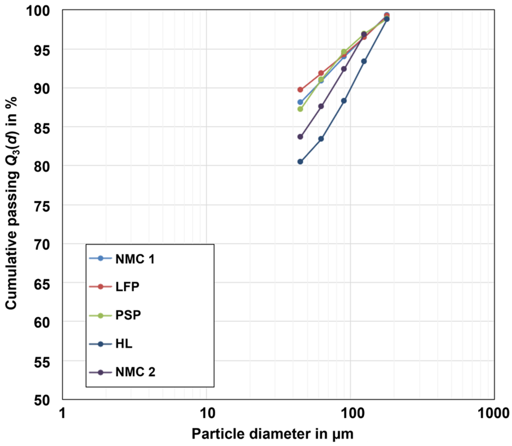
2.1.1. Particle Size Distribution (PSD)

Figure 1 shows the particle size distributions of the five black mass samples. The particle size distribution shows that approx. 90% of the NMC 1, LFP, and PSP samples are <45 µm. The HL and NMC 2 samples are coarser, with 90% < 90 µm.

2.1.2. Chemical Composition and Density

From the investigation of the element distribution in the particle size fractions, it was found that there is an enrichment for Al and Cu in fractions >45 µm. For each of the 5 black mass samples, the share of Al in fractions >45 µm was approx. 32–49% and the share of copper was approx. 36–60%. The carbon share for all the samples >45 µm was approx. 1–4%. A minor recovery of 4–7% nickel, cobalt, and manganese (Ni+Co+Mn) in fractions >45 µm was found for NMC1, NMC2, PSP, and HL samples. For the LFP sample, approx. 4% of Iron (Fe) was recovered in fractions >45 µm. In summary, the majority (>90–95%) of the metal content in the cathode active materials, as well as in the anode active materials, accumulates in the fractions <45 µm. In contrast, the residues of current collector foils, consisting of Al and Cu, are enriched in fractions >45 µm. For this reason, the samples were sieved with a mesh size of 45 µm prior to flotation in order to reduce the aluminum and copper content for the flotation feed.
Table 1 lists the chemical composition and the density of the black mass samples used for the investigations with particle size <45 µm. The main chemical elements underline the cathode materials that were present in the samples (e.g., PSP and HL black mass samples mainly contain NMC, with LCO as the second most abundant cathode active material). From the XRD measurements, it can also be seen that during thermal treatment, active materials NMC and LCO were reduced to NiO, MnO, and CoO, or were even further reduced to metallic Co and Ni.

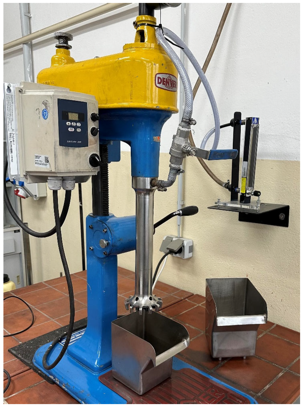
2.2. Froth Flotation for Graphite Separation

A laboratory Denver D-12 mechanical flotation machine (Metso AG, former Denver Ltd., Sparks, NV, USA) with up to 2.4 L of cell volume (see Figure 2) was used for the froth flotation tests. At the beginning of the test, the dry sample was dispersed in deionized water, with a resulting solid content of 200 g solids per liter of suspension. Then, the conditioning of the reagents was carried out with a rotational speed of 2000 rpm. The conditioning times for the dispersant were 10 min and 5 min for the collector and 1 min for the frother. The same conditioning times and rotational speed were used for subsequent reagent doses. After the first conditioning, deionized water was added to the suspension to achieve a solid content of 100 g L−1 for the froth flotation. During froth flotation, a rotational speed of 1000 rpm was applied. Regarding the air flow rate, 1.5 L min−1 was used for the 1.2 L cell, and 2 L min−1 was used for the 2.4 L cell. All recovered products were dewatered via vacuum filtration and were subsequently dried at approx. 105 °C. Finally, the dried products were deagglomerated and homogenized with a mortar and pestle for the following sample splitting and analysis. Two primary goals should be achieved during the tests, which are the production of a carbon-rich fraction (a high-carbon product, which is denoted as the froth product since the carbon is expected to accumulate in the froth) and a carbon-poor fraction (a low-carbon product, which is denoted as the cell product).
The flotation tests are performed according to the general flotation scheme shown in Figure 3 to achieve a low-carbon product and a high-carbon product. The flotation scheme consists of different flotation stages—the rougher, scavenger, and cleaner stages. The test procedure is defined in a way to reach the desired froth and cell products. The upper part of Figure 3 represents the process steps for the low-carbon (Low-C) product, whereas the lower part depicts the process steps for the carbon-rich (High-C) product.
To achieve a low-carbon product (the cell product), the samples are subjected to one rougher and several scavenger stages until there is no further froth formation. After these flotation stages, several intermediate froth products (carbon-enriched) and one cell product (Low-C) are obtained. With the froth products from the rougher and scavenger stages, a cleaner flotation is performed in sub-stages. The obtained froth products subsequently form the final high-carbon (High-C) froth product. The cell products derived from the cleaner stages are considered as intermediate products. As shown in Figure 3, flotation reagents are added at different steps during the flotation process. Based on findings from a prior study, kerosene and diesel were used as collectors, while FLOTANOLTM 7026 from Clariant (Muttenz, Switzerland) (referred to as pine oil) and Methyl–Isobutyl–Carbinol (referred to as MIBC) from Merck (Darmstadt, Germany) were used as frothers [26,27,28,29,30]. A ligninsulfonate from Borregaard (Sarpsborg, Norway) (PioneraTM DP-750) was applied as the dispersant.
To evaluate the use of the flotation graphite as a secondary raw material in refractory products representing an open-loop recycling approach for the flotation graphite, a Magnesia Carbon brick was chosen in this study (MgO-C). Two MgO-C bricks were compared, one standard MgO-C brick mixture (low-carbon MgO-C brick with ~3 wt.% carbon) and a mixture in which 1 wt.% of the carbon was substituted by the flotation graphite. Results of material analyses in terms of thermal and mechanical strength are discussed below (Section 3.3).

3. Results

In the following section, the results, especially in relation to the qualities of the froth product (carbon-rich fraction) and the cell product (carbon-poor fraction) obtained, are analyzed and compared.

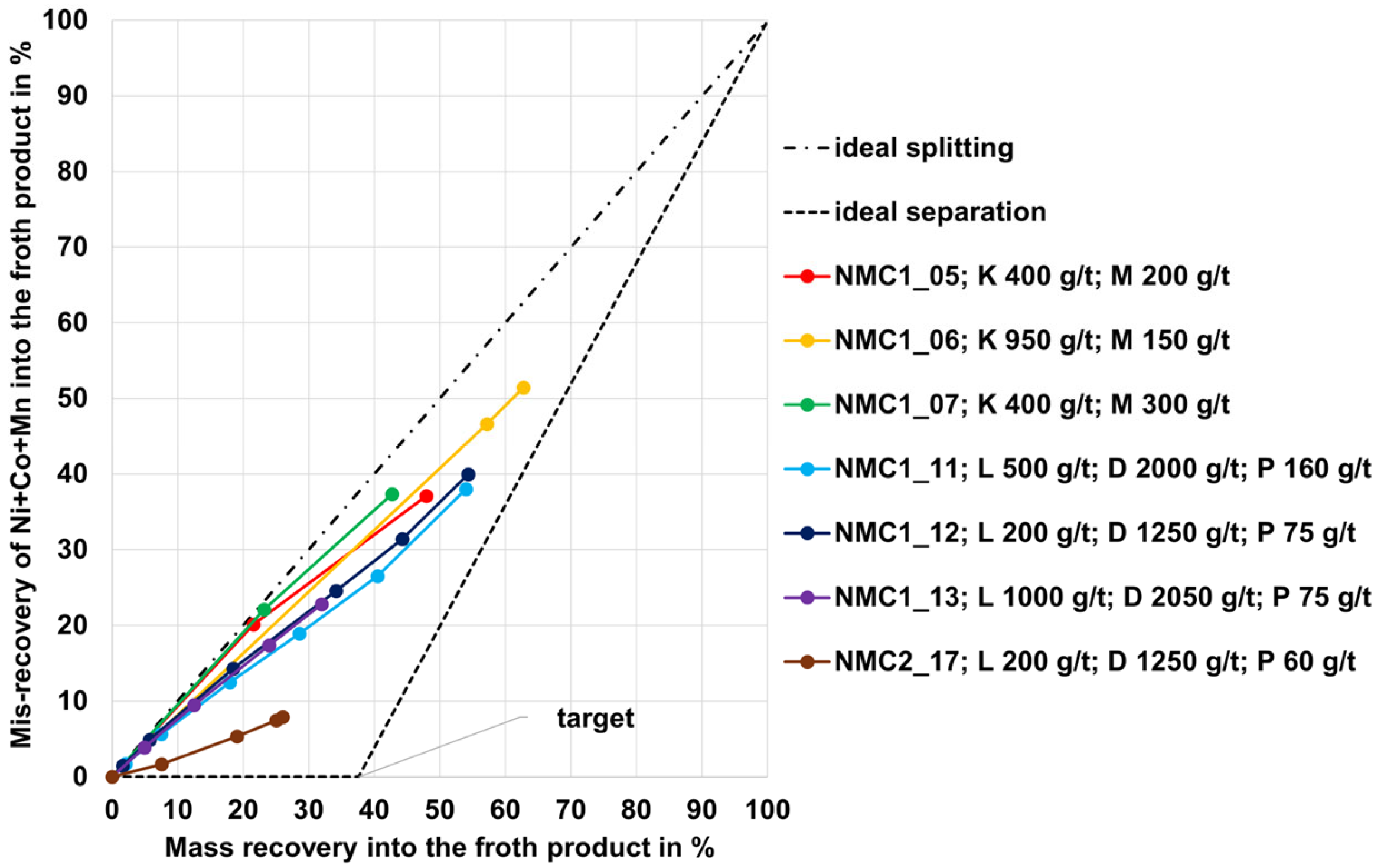
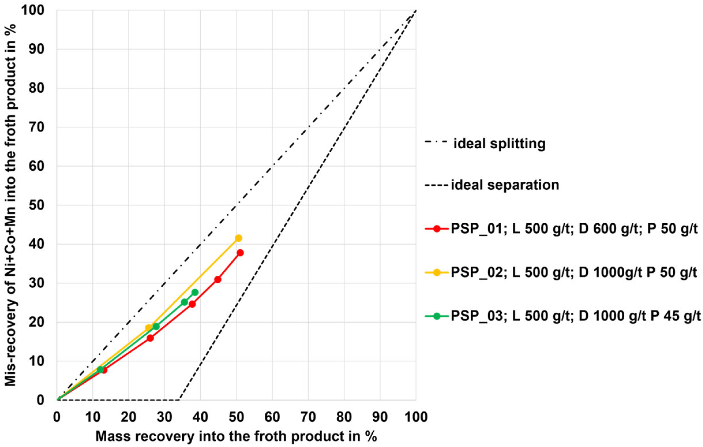
3.1. Flotation Results for the NMC, PSP, and LFP Black Mass

Figure 4 shows an exemplary illustration of the flotation test results for the NMC 1 and NMC 2 black mass samples, illustrated in the form of Mayer upgrading curves. This kind of diagram is a visualization of the separation efficiency that enables the evaluation of the flotation tests without the need to execute an explicit carbon analysis. The corresponding test results in the form of the grade of the final froth product (all froth products together) are given for the best sorting results in Table 2.
In Figure 4, the mis-recovery of Ni+Co+Mn (which is the undesirable recovery of these elements into the froth product) from the NMC samples is represented on the y-axis, while the mass recovery into the froth product is represented on the x-axis. Two conceptual curves are shown in Figure 4. One of them is the ideal splitting (straight dashed-dotted line) representing a separation process without any enrichment of the carbon in the froth product (worst case). The other curve represents the ideal separation (dashed line) and ranges horizontally in the first part up to the optimum mass recovery at a mis-recovery of 0%. The optimum mass recovery corresponds to the carbon grade in the flotation feed (NMC1 37.6 wt.% carbon, see Table 1). This point (“target”) represents a total recovery of the carbon in the froth product without any impurities of Ni+Co+Mn (best case). In the second part, the curve runs straight to 100% mis-recovery into the froth product and 100% mass recovery into the froth product. This means that any further mass recovery would lead to a mis-recovery of Ni+Co+Mn. The result is a triangular area between the two conceptual curves. Upgrading curves within this area represent sorting results with an enrichment of carbon in the froth product. The closer the upgrading curve is to the ideal separation and the closer it ends to the target point, the better the sorting result. This means that there is less mis-recovery and therefore the graphite is more selectively enriched and recovered into the froth product. Conversely, this means that upgrading curves close to the ideal splitting mean a poor sorting result. In this case, a higher mis-recovery of Ni+Co+Mn takes place. This means a non-selective enrichment of the graphite in the froth product. Upgrading curves to the left of this triangular area would represent a separation result that corresponds to an enrichment of Ni+Co+Mn in the froth product instead of carbon, whereas upgrading curves to the right are not physically possible. Each data point on the upgrading curves shown in Figure 4 represents a rougher and subsequent scavenger stage (further details stages numbers and reagent dosages can be found in Appendix A, Table A1).
The flotation testing for sample NMC1 can be divided into two different reagent regimes. From Figure 4, the trend can be seen that the upgrading curves for the regime that uses ligninsulfonate as dispersant, diesel as collector, and pine oil as frother (further referred as regime LDP) are underneath the upgrading curves for the regime that uses kerosene as collector and MIBC as frother (further referred as regime KM). From this, it can be concluded that the sorting results for regime LDP are better. However, with a mass recovery between 42 and 62% and a mis-recovery of Ni+Co+Mn between 37 and 51%, all upgrading curves for sample NMC1 exceed the optimum mass recovery of the “target point” (37.6%) and are close to the ideal splitting and therefore represent an inadequate sorting result. Nevertheless, it can be stated that the variation of the reagent dosage in regime KM has nearly no influence on the sorting result (in terms of selective enrichment of carbon). For the LDP regime, a higher dosage of lignosulfonate requires an increased dosage of diesel and pine oil. However, the upgrading curves are almost on top of each other in this case, which means that the sorting result (selective enrichment of carbon) is not affected. The upgrading curve for sample NMC2 with reagent regime LDP is clearly below that of sample NMC1 and thus shows the most selective enrichment of carbon in the froth product.
The exemplary chosen grades of the froth and the cell products reflect the findings from Figure 4 in absolute values (see Table 2). The analyses shown here only include the elements of main interest (C, Co, Ni, Mn, Al, Cu). The high mis-recovery of Ni+Co+Mn into the froth product (approx. 40%) for sample NMC 1 corresponds to a grade of approx. 28 to 30 wt.%. As a result, the carbon grade is only enriched to approx. 63 to 65 wt.%. Sample NMC 2 shows a more selectively enriched froth product since the grade of Ni+Co+Mn is only at approx. 9 wt.%. Al+Cu are enriched in the cell product and the final carbon grade in the cell product account in the range between approx. 7 and 10 wt.%. Tests with the LFP sample are unsuccessful since the sample is non-dispersible in water.
For the PSP black mass sample (mixture of graphite anode material and NMC as well as LCO cathode material), the flotation results are given in Figure 5 as MAYER upgrading curves. For the tests, the reagent regime LDP is applied with different dosages and numbers of flotation stages. The resulting upgrading curves are quite similar to those of sample NMC 1. With a mass recovery between 38 and 51% and a mis-recovery of Ni+Co+Mn between 27 and 41%, all curves exceed the optimum mass recovery of 33.9%. Thus, these sorting results are also inadequate regarding the selective enrichment of carbon in the froth product. The absolute values in the form of the grade of the final froth product are given in Table 2 (last row), which are comparable to those from sample NMC 1.

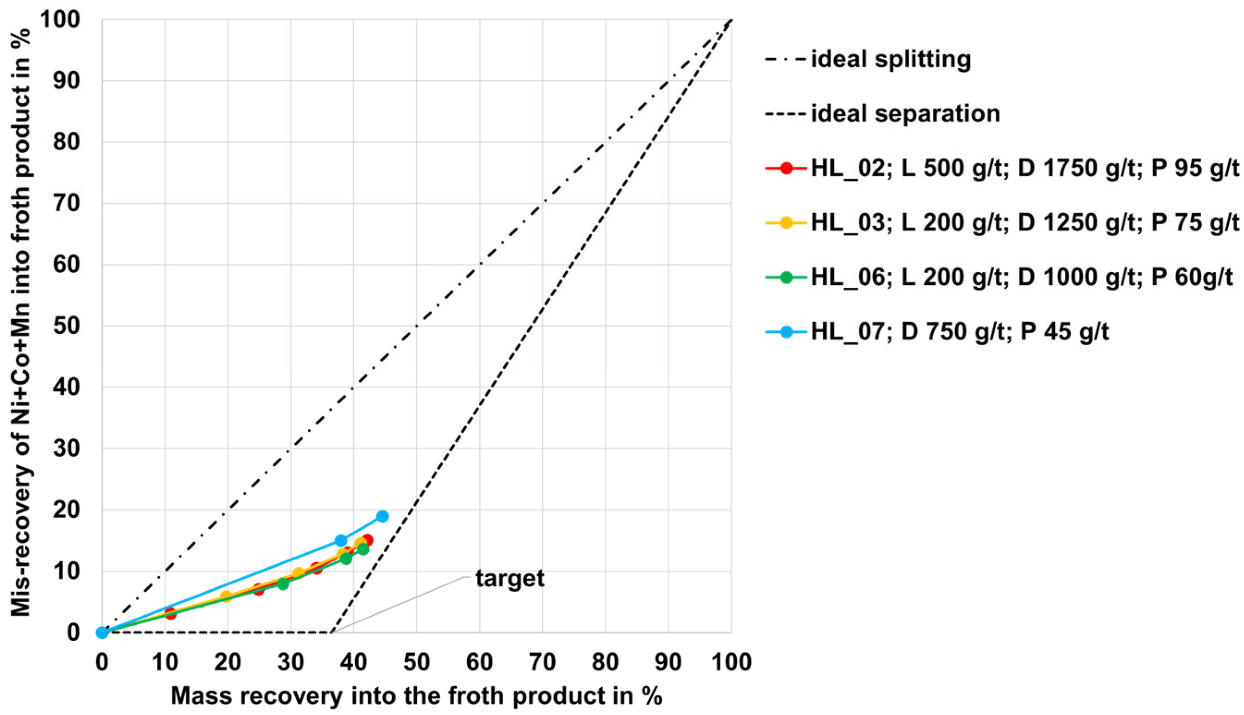
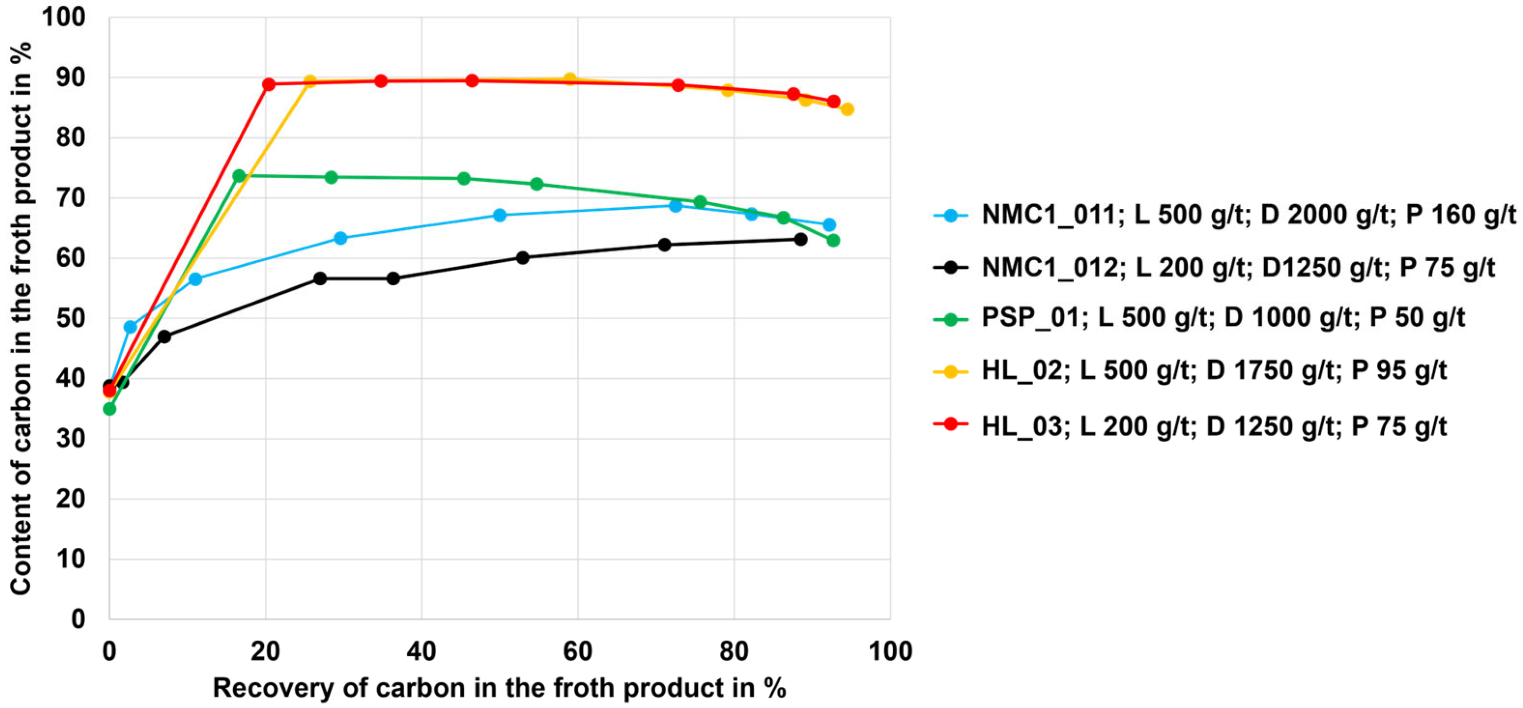
3.2. Flotation Results for the HL Black Mass

Table 3 summarizes some exemplary compositions of the froth and cell products for the HL black mass samples (mixture of graphite anode material and NMC as well LCO as cathode material). All flotation test results are shown as MAYER upgrading curves in Figure 6. With a mis-recovery between 15 and 20% for Ni+Co+Mn into the froth product with a corresponding mass recovery into the froth product between 34 and 45% the upgrading curves are close to the ideal separation curve, and they end near the “target point”. This shows an acceptable selective enrichment of carbon in the froth product. The use of ligninsulfonate as a dispersant shows that a lower misrecovery and thus a more selective enrichment of carbon is achieved (upgrading curve HL_07 is above the others). Furthermore, the use of pine oil instead of MIBC as a frother shows that the same sorting result is achieved, whereby the dosage of collector and frother can be reduced in total (comparison HL_01). Further optimization of the reagent regime shows no improvement in the sorting result. However, it can also be determined for sample HL that a lower dosage of lignosulfonate leads to a decrease in the required diesel and pine oil dosage.
Froth products with a carbon content of approx. 85 wt.% are thus achieved, which contain impurities of approx. 15 wt.% Ni+Co+Mn.
Based on the findings from the rougher and scavenger stages, a test with a cleaner stage was performed. The test parameters and results can be found in Table 4. With the rougher stage and two scavenger stages, a carbon recovery of 94% with a carbon grade of 86 wt.% could be achieved in the froth product (see columns “Carbon grade” and “Carbon recovery” in the line “Ro-Scav2-Froth” in Table 4). A further improvement in the carbon grade was achievable with the cleaner flotation stage ranging from 94 to 91 wt.%, with recovery from 63 to 89% (see columns “Carbon grade” and “Carbon recovery” in lines “Clnr1-Froth1” to “Cnlr1-Froth4” in Table 4). In the resulting high-carbon product, the main impurities are Ni, Co, Mn, Al, and Cu. The final high-carbon product (denoted as “Clnr1-Froth4” in Table 4) was used as a secondary carbon source for refractory material tests (see Section 3.3).

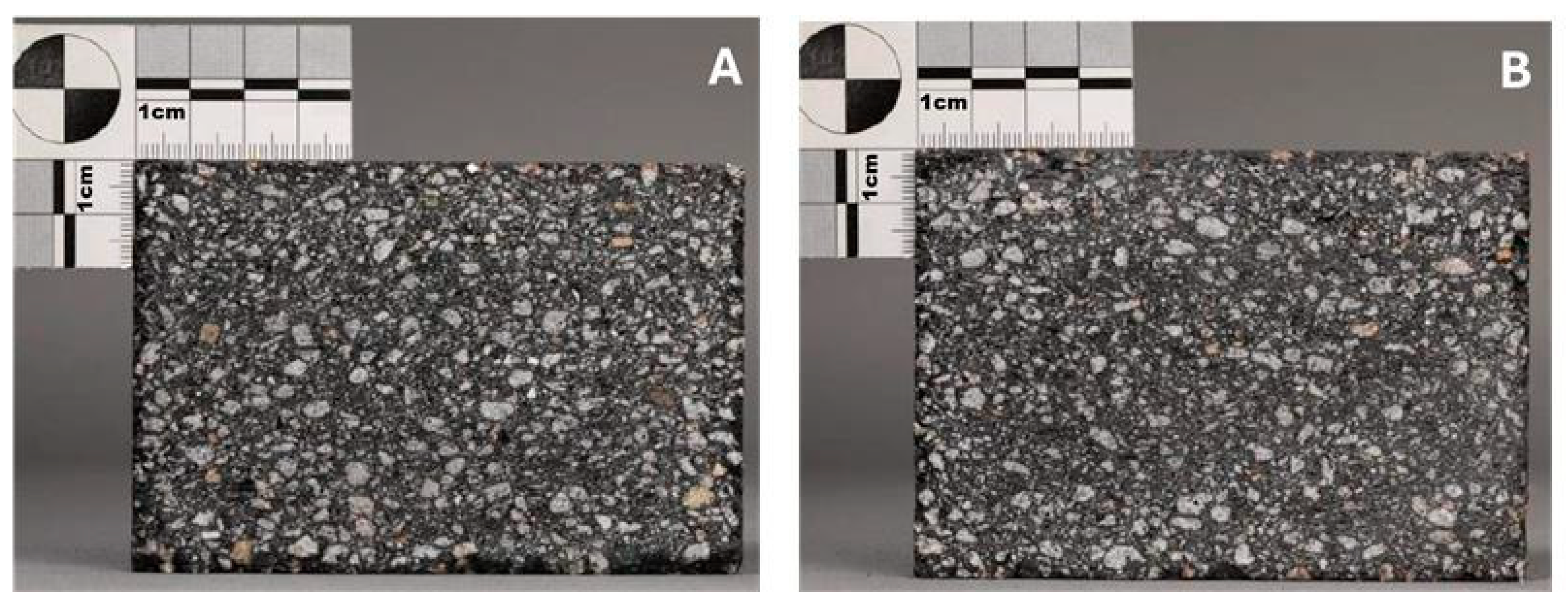
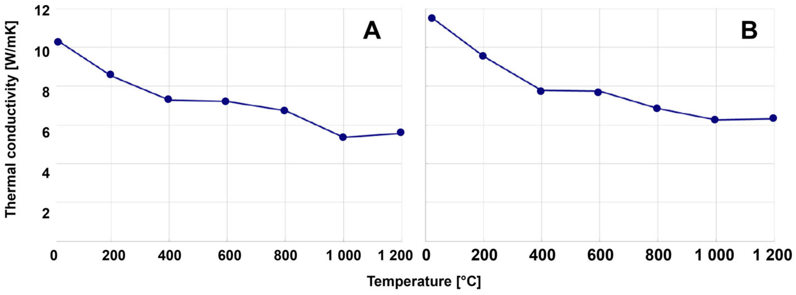
3.3. Evaluation of the Flotation Graphite as a Secondary Raw Material for Refractory Production

As described and illustrated in Section 3.1 and Section 3.2, certain shares of the other elements, Ni, Co, Mn, Al, and Cu, are transferred into the carbon-rich froth product. This may hinder a direct reuse of the flotation graphite for battery anodes. Open-loop recycling practices contribute towards higher recycling rates of LIB fractions. For the refractory industry, carbon represents an important raw material to produce magnesia carbon (MgO-C) bricks. Such bricks are used for the steel industry in metallurgical aggregates, such as for crude steelmaking via a Basic Oxygen Furnace (BOF) or an Electric Arc Furnace (EAF), as well as in metallurgical ladles that are used for crude steel refining (as a secondary metallurgical operation). To evaluate the use of the flotation graphite as a secondary raw material in MgO-C brick products, two MgO-C bricks were compared—one standard MgO-C brick mixture (low-carbon MgO-C brick with ~3 wt.% carbon) and a mixture in which 1 wt.% of the carbon was substituted by flotation graphite. The addition of carbon black, and in this case the flotation graphite, is aiming a porosity reduction in the MgO-C brick. A typical amount for the pore filling materials is 1 wt.%. Adding more of this ultra-fine material (soot fraction as standard source) induces negative production-related issues. This is why 1 wt.% was selected as the ratio for the flotation graphite substitution and not the whole 3 wt.%. Figure 7 shows a cut section of the two studied MgO-C bricks (A: standard refractory brick with 3 wt.% carbon; B: refractory brick with 1 wt.% recycled graphite content). Both samples show a flawless microstructure with an overall homogeneous distribution of the components, which is an important indicator that flotation graphite does not negatively affect the brick structure.
Certain relevant properties were determined via chemical analysis and physical parameters, such as density, porosity, cold crushing strength (CCS), hot modulus of rupture (HMOR—the maximum bending stress that can be applied to that material before it breaks), thermal conductivity, or hot relaxation. Figure 8 shows a comparison of the thermal conductivity for both tested bricks. Thermal conductivity is slightly higher for the brick with flotation graphite (e.g., ~8 W m−1 K−1 at 600 °C for the brick with the flotation graphite compared to ~7 W m−1 K−1 for the standard brick) but still within an acceptable range according to the expertise of refractory producers. No further material properties were analyzed since the ones mentioned here represent the main important parameters to compare the principal quality of refractory bricks independent of the raw materials used. From refractory producer side, it can therefore be considered that the brick comprising flotation graphite seems to be mechanically and thermally stable from current state of knowledge.
Table 5 shows the trends in some of the physical parameters when partially substituting standard carbon (fine-grained pore filling soot fraction) with flotation graphite.
Although some mechanical parameters that are important for brick strength are lower when using flotation graphite (cf. CCS and HMOR), the values for the coked sample (coking at 1500 °C) lead to the assumption that the recycling graphite from the froth flotation is principally suitable as a carbon source for MgO-C bricks.

4. Discussion

As shown in Section 3, a certain degree of selectivity is reached when applying froth flotation to black mass samples. However, it was also found that not all black mass samples, especially when considering the cathode material fractions, show the same level of selectivity, which leads to a mis-recovery of undesired elements (i.e., Co, Ni, Mn, Al, and Cu) into the carbon-rich flotation product.

4.1. Comparison of Black Mass Types According to the Carbon Content

An extended carbon determination was carried out for the most optimum test results obtained so far. Therefore, specific test results are shown in the form of FUERSTENAU-2 upgrading curves in Figure 9.
In Figure 9, the recovery of carbon into the froth product is shown on the y-axis, while the recovery of tailings (i.e., every other element except carbon) into the froth product is shown on the x-axis. There are two conceptual curves; the first is a diagonal dashed line depicting ideal splitting with the meaning of no selective carbon enrichment in the froth product (worst case). The other ideal curve is represented by the y-axis, depicting an ideal separation (best case). Upgrading curves inside of the triangular area between those two conceptual curves have a selective enrichment of carbon into the froth product. This is because the recovery of carbon is higher than the recovery of the tailings. For selective carbon separation, the aim is that the end of the upgrading curves is near the left upper corner.
The results reveal that each black mass sample needs a different reagent regime and flotation scheme. High carbon recovery rates in the froth product of 90% or even higher are reached for all black mass samples (except the LFP black mass sample as it could not be completely dispersed in water; see Section 3.1). The NMC and PSP samples show a similar tailings recovery rate of ~30%. The HL sample shows the lowest undesired recovery of non-carbon elements in the froth product (~10%), representing the best flotation behavior in terms of a selective carbon enrichment into the froth product. Figure 10 illustrates the carbon recovery in the froth product, depending on the corresponding carbon content (Halbich upgrading curves).
The y-axis shows the carbon content in the froth product, whereas the carbon recovery into the froth product is displayed on the x-axis. The curve begins with a recovery of 0%, representing the feed material (corresponding to an initial carbon content in the black mass samples of ~40 wt.%). The curves must be interpreted from left to right, where each data point on the curve represents an intermediate froth product during the flotation scheme (i.e., after every rougher and scavenger stage). It is evident that the HL black mass sample shows the best separation selectivity for the chosen flotation parameters and reagents. The final carbon contents in the froth product of ~90 wt.% are reached. The PSP black mass shows the second best flotation selectivity, followed by the NMC samples (NMC 1 and NMC 2).
It is also relevant to have a closer look into the quality of the cell product to evaluate flotation efficiency. Therefore, Figure 11 illustrates the flotation results in the form of HALBICH upgrading curves.
The y-axis displays the recovery of carbon in the cell product, while the carbon content in the cell product is shown on the x-axis. The curve begins with a recovery of 100%, representing the feed material. The curves must be interpreted from right to left, where each data point on the curves represents an intermediate cell product during the flotation scheme (i.e., after every scavenger step). The recovery of carbon was in the range of 5–10% for the different black mass samples with corresponding carbon contents between 4 and 10 wt.%. In case a certain carbon content was valuable, e.g., to reduce the demand of a reducing agent during a subsequent pyrometallurgical black mass treatment (assuming that solid carbon powder is used to pyrometallurgically reduce metals from the black mass), the flotation process can principally be stopped at any position on the curve, i.e., after a certain number of scavenger steps.

4.2. Use of Flotation Graphite as a Secondary Carbon Carrier in Other Energy-Intensive Industries

The principal suitability to use the flotation graphite in the energy-intensive refractory industry as a secondary raw material for MgO-C refractory bricks was demonstrated in Section 3.3. The steel industry is another important energy- and resource-intensive sector that requires certain quantities of carbon. Even in future decarbonized steel production routes, carbon is still required to a certain extent. For example, carbon sources are of great importance in the Electric Arc Furnace (EAF), occupying two main roles. On the one hand, it is required for energetic use as an additional (chemical energy) input alongside electrical energy. On the other hand, carbon sources are used as slag foaming agents. Solid carbon sources are principally used in the EAF in two ways. The charge carbon is used together with scrap or other iron sources (e.g., sponge iron originating from a direct reduction in the briquetted form, i.e., hot briquetted iron—HBI) into the EAF, together with additives, at the beginning of the heating process. This carbon serves to carburize the melt, thereby contributing to slag foaming and, via the direct oxidation of the carbon during meltdown, achieving a chemical energy input. On the other hand, the injection carbon is brought into the EAF via lances or injectors, together with oxygen, to generate CO/CO2 bubbles within the slag and thereby foaming the slag [31]. According to the Best Available Techniques (BATs) reference document for iron and steel production, ~15 kg of coal is used per ton of steel produced in the EAF (sum of charge and injected carbon) [12]. Slag foaming in the EAF is a well-established and widely used method to significantly increase the efficiency of the energy transfer in the furnace. The shielding of the electric arcs by the foaming slag reduces the energy loss via the water-cooled furnace walls and roof, thus enabling a significantly improved energy transfer from the arc to the melt. In addition, slag foaming has a stabilizing effect on the arcs and reduces the noise emissions of the EAF. Approximately 5–10 kg of injected carbon is used in EAFs per ton of crude steel [32]. In particular, the use of flotation graphite as an injection carbon could be interesting considering the grain size of ~45 µm being principally useful for an injection system. One critical point here is the content of undesired metals coming with the flotation graphite into the EAF process, other than the carbon, which are, depending on the black mass feed material used, Co, Cu, Ni, Mn, or Al. Special attention is necessary since some metals, such as Cu, cannot be removed from the steel melt anymore. Depending on the final steel grade to be produced, different tramp element levels must be kept. Furthermore, tramp elements can negatively influence steel properties during further downstream processing.

5. Conclusions

This study investigated the question of open-loop recycling for graphite separated from LIB black mass (which is a mixture of anode and cathode materials) via froth flotation. Black mass samples originating from different LIB types were used to produce a carbon-poor and a carbon-enriched fraction. The optimization of the flotation parameters was carried out depending on the black mass chemistry, i.e., the number of flotation stages (i.e., carbon separation and cleaning stages) and the dosing of flotation agents. The following main findings were discussed:
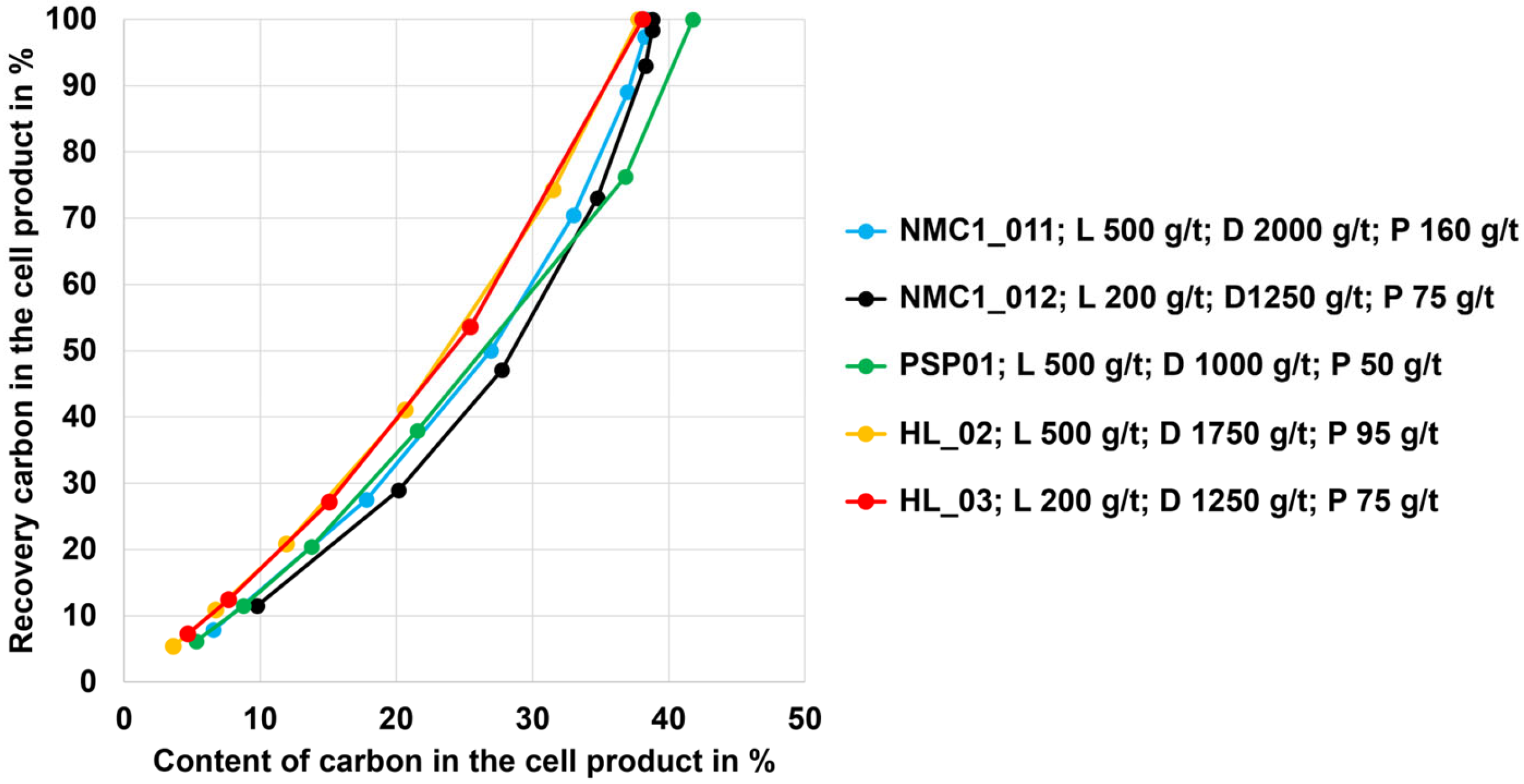
  • Black mass containing NMC and LCO cathode materials could be treated using froth flotation with graphite recovery rates in the range between 90 and 95%; the low-carbon (cell) products showed final carbon contents between 4 and 10 wt.% (as such, the goal to derive a low-carbon product was reached).
  • The currently investigated black mass containing the LFP cathode material did not disperse well in water and therefore showed no selectivity with regard to graphite separation via froth flotation (dispersion may be different with other LFP samples).
  • For each of the different black mass samples investigated, a separate flotation scheme including a reagent regime must be developed. There is likely an influence of the conditions during the thermal LIB pre-processing step or another influence of the different cell geometries on the separation efficiency (this hypothesis needs to be investigated more intensively). The black mass sample HL (mixture of NMC and LCO cathode and graphite anode material) and the NMC black mass samples showed the highest selectivity (carbon-enriched product with 8–10 wt.% of undesired metals Co, Cu, Ni, Mn, and Al from the black mass). The PSP black mass (also a mixture of NMC and LCO cathode and graphite anode material) showed less selectivity with ~30 wt.% undesired metal contents in the carbon-enriched product.
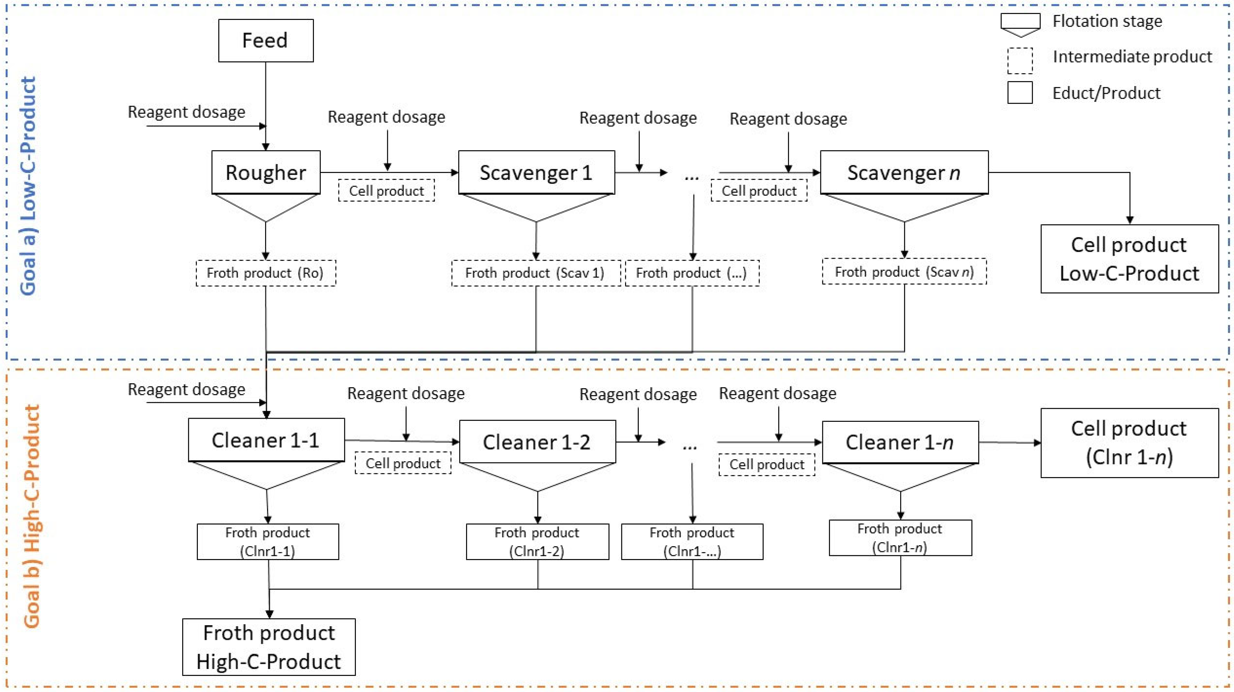
  • A flotation scheme was elaborated, comprising rougher and scavenger steps, and the separation of carbon-enriched products was achieved. Additionally, the flotation concept allows for a certain flexibility in terms of required product quality, i.e., it is possible to end the flotation process at an earlier stage (i.e., at a lower number of scavenger stages) to end with a higher carbon content in the cell product (if carbon is required as a reducing agent for a subsequent pyrometallurgical treatment to recover metals from the black mass).
  • The carbon-enriched product was used as a secondary carbon source for a refractory material (magnesia carbon bricks), whereas an analysis of the brick chemistry, as well as thermo-mechanic properties in terms of density, porosity, cold crushing strength, hot modulus of rupture (the maximum bending stress that can be applied to a material before it breaks), or thermal conductivity, showed no negative influence on brick quality.
  • It could be demonstrated that flotation graphite can be used as a secondary source for non-battery applications, representing a valuable positive example that contributes to a more complete closure of the battery life cycle and thus to a more circular economy.
For future research, several following challenges should be considered, whereas more insights into economic and environmental impact analyses would also be required to gain more information about the potential to implement specific flotation steps into existing LIB recycling processes:
  • Upscaling of the currently used froth flotation (process sequence and flotation reagents) to obtain more reproducible data about the expected graphite product quality including impurities (tramp elements) present in the flotation graphite.
  • Elaboration of a comprehensive connection between operating conditions of the thermal spent LIB pre-processing step and carbon separation efficiencies obtained via froth flotation.
  • In case the flotation graphite is considered to be used for open-loop recycling practices in industrial sectors other than battery production, different application-oriented scenarios must be comprehensively investigated; in case the flotation graphite is used as carbon carrier in an EAF for crude steelmaking, slag foaming efficiency, as well as the transfer of tramp elements into the metal melt, should be comprehensively investigated; in case the flotation graphite is used for refractory production (magnesia-carbon bricks), the high-temperature behavior of the bricks with the flotation graphite should be investigated in long-term trials.
  • In-depth discussion on the economic viability of open-loop recycling approaches compared to other graphite recovery methods.
  • Comparison of the environmental impact of graphite flotation and subsequent graphite recycling versus primary graphite production to gain added value with regards to circular economy contributions.

Author Contributions

Conceptualization: J.R. and S.S.; methodology: J.R. and S.S.; validation: S.S., B.R., A.A. and H.K.; formal analysis: J.R.; investigation: S.S., S.M. and B.R.; resources: S.S., A.A. and H.K.; data curation: S.S.; writing—original draft preparation: J.R.; writing—review and editing: S.S., B.R., S.M., A.A., H.K, T.N. and S.L.; visualization: S.S. and J.R.; supervision: B.R., A.A. and H.K.; project administration: B.R. and J.R.; funding acquisition: J.R. and S.L. All authors have read and agreed to the published version of the manuscript.

Funding

This research was funded by the Austrian Research Promotion Agency (grant number 888343/FO999888343).

Data Availability Statement

The data are contained in the study.

Acknowledgments

The authors gratefully acknowledge the funding support of K1-MET GmbH, the metallurgical competence center. The Module FuLIBatteR is supported by COMET (Competence Center for Excellent Technologies), the Austrian program for competence centers. COMET is funded by the Federal Ministry for Climate Action, Environment, Energy, Mobility, Innovation and Technology, the Federal Ministry for Labour and Economy, the Federal States of Upper Austria and Styria, as well as the Styrian Business Promotion Agency (SFG). Furthermore, Upper Austrian Research GmbH continuously supports the Module. In addition to the public funding from COMET, this Module is partially financed by the company partners Audi, BRAIN Biotech, Ebner Industrieofenbau, RHI Magnesita, Saubermacher, TÜV SÜD Landesgesellschaft Österreich, VTU Engineering, and voestalpine High-Performance Metals, as well as the scientific partners ACIB, Coventry University, Montanuniversitaet Leoben, BOKU University, and UVR-FIA.

Conflicts of Interest

Astrid Arnberger was employed by the company Saubermacher Dienstleistungs AG. Hartwig Kunanz was employed by the company RHI Magnesita GmbH. The authors declare no conflicts of interest.

Appendix A

The current appendix (Table A1) is dedicated to Section 2.2 and represents an amendment to Figure 3 to explain the different flotation agents used for the black mass samples.
Table A1. Summary of flotation stages, reagents, and dosages (g/t) for the tested black mass samples.
Test No.Flotation StageReagent Test No.Flotation StageReagent
Type and Dosage in g/t Type and Dosage in g/t
NMC_1_05Ro *K 250; M 150 PSP_02RoL 500; D 500; P 30
Scav1K 150; M 50 Scav1D 500; P 15
TotalK 400; M 200 TotalL 500; D 1000; P 45
NMC_1_06RoK 800; M 150 PSP_03RoD 500; P 10
Scav1K 150 Scav1D 250; P 10
TotalK 950; M 150 Scav2D 250; P 10
NMC_1_07RoK 250; M 250 Scav3D 250; P 10
Scav1K 150; M 50 TotalD 1250; P 40
TotalK 400; M 300 HL_01RoL 500; D 800; M 100
NMC_1_11RoL 500; D 500; P 30 Scav1D 500; M 100
Scav1D 250; P 15 Scav2D 500; M 100
Scav2D 250; P 15 Scav3D 500; M 100
Scav3D 250; P 15 Scav4D 500; M 100
Scav4D 250; P 15 TotalL 500; D 2800; M 500
Scav5D 250; P 20 HL_02RoL 500; D 500; P 30
TotalL 500; D 1750; P 110 Scav1D 250; P 15
NMC_1_12RoL 200; D 500; P 30 Scav2D 250; P 15
Scav1D 250; P 15 Scav3D 250; P 15
Scav2D 250; P 15 Scav4D 500; P 20
Scav3D 250; P 15 TotalL 500; D 1750; P 95
Scav4D 250; P 15 HL_03RoL 200; D 500; P 30
Scav5D 300; P 20 Scav1D 250; P 15
TotalL 200; D 1800; P 110 Scav2D 250; P 15
NMC_1_13RoL 1000; D 1300; P 30 Scav3D 250; P 15
Scav1D 250; P 15 TotalL 200; D 1250; P 75
Scav2D 250; P 15 HL_06RoL 200; D 500; P 30
Scav3D 250; P 15 Scav1D 250; P 15
TotalL 1000; D 2050; P 75 Scav2D 250; P 15
NMC_2_17RoL 200; D 500; P 30 TotalL 200; D 1000; P 60
Scav1D 500; P 15 HL_07RoD 500; P 30
Scav2D 250; P 15 Scav1D 250; P 15
Scav3D 500; P 15 TotalD 750; P 45
TotalL 200; D 1750; P 75
PSP_01RoL 500; D 100; P 10
Scav1D 100; P 10
Scav2D 100; P 10
Scav3D 100; P 10
Scav4D 100; P 10
TotalL 500; D 600; P 50
* Ro—Roughger; Scav—Scavenger.

References

  1. Goodenough, J.B.; Park, K.-S. The Li-ion rechargeable battery: A perspective. J. Am. Chem. Soc. 2013, 135, 1167–1176. [Google Scholar] [CrossRef] [PubMed]
  2. Asenbauer, J.; Eisenmann, T.; Kuenzel, M.; Kazzazi, A.; Chen, Z.; Bresser, D. The success Story of graphite as a Lithium-Ion anode material—Fundamentals, remaining challenges, and recent developments including silicon (oxide) composites. Sustain. Energy Fuels 2020, 4, 5387–5416. [Google Scholar] [CrossRef]
  3. Larcher, D.; Beattie, S.; Morcrette, M.; Jumas, K.E.; Tarascon, J. Recent findings and prospects in the field of pure metals as negative electrodes for Li-ion batteries. J. Mater. Chem. 2007, 17, 3759–3772. [Google Scholar] [CrossRef]
  4. European Carbon and Graphite Association. Graphite in Batteries. Available online: https://ecga.net/wp-content/uploads/2023/02/Graphite-in-batteries_Infosheet_final.pdf (accessed on 16 September 2024).
  5. European Commission. Framework for Ensuring a Secure and Sustainable Supply of Critical Raw Materials (COM(2023) 160 Final); European Commission: Brussels, Belgium, 2023. [Google Scholar]
  6. European Union. Regulation (EU) 2023/1542 Concerning Batteries and Waste Batteries. 2023. Available online: https://eur-lex.europa.eu/legal-content/EN/TXT/PDF/?uri=CELEX:32023R1542 (accessed on 5 December 2024).
  7. Han, S.-J.; Xu, L.; Chen, C.; Wang, Z.-Y.; Fu, M.-L.; Yuan, B. Recovery of graphite from spent lithium-ion batteries and its wastewater treatment application: A review. J. Sep. Purif. Technol. 2024, 330, 125289. [Google Scholar] [CrossRef]
  8. Yildiz, T.; Wiechers, P.; Nirschl, H.; Gleiß, M. Direct recycling of carbon black and graphite from an aqueous anode slurry of lithium-ion batteries by centrifugal fractionation. Next Energy 2023, 2, 100082. [Google Scholar] [CrossRef]
  9. Ahuis, M.; Aluzoun, A.; Keppeler, M.; Melzig, S.; Kwade, A. Direct recycling of lithium-ion battery production scrap—Solvent-based recovery and reuse of anode and cathode coating materials. J. Power Sources 2024, 593, 233995. [Google Scholar] [CrossRef]
  10. Zhao, L.; Xin-yu, Z.; Yi-ye, L.; Hao, J.; Yan-qin, H.; Ming-xin, X.; Qiang, L. Recovery of electrode materials from a spent Lithium-Ion Battery through a pyrolysis-coupled mechanical milling method. Energy Fuels 2024, 38, 9280–9319. [Google Scholar] [CrossRef]
  11. Rong, T.; Yuan, Y.; Yang, H.; Yu, H.; Zuo, H.; Wang, J.; Xue, Q. Investigation of the enrichment-purification process and electrochemical performance of kish graphite in dust from blast furnace tapping yard. J. Waste Manag. 2024, 175, 121–132. [Google Scholar] [CrossRef]
  12. Remus, R.; Aguado Monsonet, M.A.; Roudier, S.; Delgado Sancho, L. Best Available Techniques (BAT) Reference Document for Iron and Steel Production; European Commission, Joint Research Centre: Brussels, Belgium, 2013. [Google Scholar]
  13. Jia, P.; Sun, J.; Li, S.; Wang, W.; Song, Z.; Zhao, X.; Mao, Y. A feasible recycling route for spent graphite: Microwave-assisted puffing with Fe2O3 loading to construct high-performance anode for lithium-ion batteries. Mater. Today Sustain. 2024, 25, 100620. [Google Scholar] [CrossRef]
  14. Mancini, M.; Hoffmann, M.F.; Martin, J.; Weirather-Kostner, D.; Axmann, P.; Wohlfahrt-Mehrens, M. A proof-of-concept of direct recycling of anode and cathode active materials: From spent batteries to performance in new Li-ion cells. J. Power Sources 2024, 595, 233997. [Google Scholar] [CrossRef]
  15. Subramanyan, K.; Jyothilakshmi, S.; Ulaganathan, M.; Lee, Y.-S.; Aravindan, V. An efficient upcycling of graphite anode and separator for Na-ion Batteries via solvent-co-intercalation process. Carbon 2024, 216, 118525. [Google Scholar] [CrossRef]
  16. Milian, Y.e.; Jamett, N.; Cruz, C.; Herrera-Leon, S.; Chacana-Olivares, J. A comprehensive review of emerging technologies for recycling spent lithium-ion batteries. Sci. Total Environ. 2024, 910, 165843. [Google Scholar] [CrossRef]
  17. Vanderbruggen, A.; Sygusch, J.; Rudolph, M.; Serna-Guerrero, R. A contribution to understanding the flotation behavior of lithium metal oxides and spheroidized graphite for lithium-ion battery recycling. Colloids Surf. A Physicochem. Eng. Asp. 2021, 626, 127111. [Google Scholar] [CrossRef]
  18. Savihirta, H.; Wilson, B.P.; Lundström, M.; Serna-Guerrero, R. A study on recovery strategies of graphite from mixed lithium-ion battery chemistries using froth flotation. Waste Manag. 2024, 180, 96–105. [Google Scholar] [CrossRef] [PubMed]
  19. Olutogun, M.; Vanderbruggen, A.; Frey, C.; Rudolph, M.; Bresser, D.; Passerini, S. Recycled graphite for more sustainable lithium-ion batteries. Carbon Energy 2024, 6, e483. [Google Scholar] [CrossRef]
  20. Drzymała, J.; Swatek, A. Mineral Processing: Foundations of Theory and Practice of Mineralogy, 1st ed.; Wroclaw University of Technology: Wroclaw, Poland, 2008. [Google Scholar]
  21. Wills, B.A.; Finch, J.A. Chapter 12—Froth Flotation. In Wills’ Mineral Processing Technology, 8th ed.; Butterworth-Heinemann: Oxford, UK, 2016; pp. 265–380. [Google Scholar]
  22. Chehreh Chelgani, S.; Rudolph, M.; Kratzsch, R.; Sandmann, D.; Gutzmer, J. A review of graphite beneficiation techniques. Miner. Process. Extr. Metall. Rev. 2016, 37, 58–68. [Google Scholar] [CrossRef]
  23. Vasumathi, N.; Sarjekar, A.; Chandrayan, H.; Chennakesavulu, K.; Reddy, G.; Ramanjaneya, V.K. A Mini Review on Flotation Techniques and Reagents Used in Graphite Beneficiation. Int. J. Chem. Eng. 2023, 2023, 1007689. [Google Scholar] [CrossRef]
  24. Andreola, F.; Castellini, E.; Ferreira, J.M.F.; Olhero, S.; Romagnoli, M. Effect of sodium hexametaphosphate and ageing on the rheological behaviour of kaolin dispersions. Appl. Clay Sci. 2006, 31, 56–64. [Google Scholar] [CrossRef]
  25. Arnberger, A.; Coskun, E.; Rutrecht, B. Recycling von Lithium-Ionen Batterien. In Recycling und Rohstoffe, 11th ed.; Thiel, S., Thomé-Kozmiensky, E., Goldmann, D., Eds.; Thomé-Kozmiensky Verlag GmbH: Neuruppin, Germany, 2018; pp. 583–599. [Google Scholar]
  26. Salces, A.M.; Bremerstein, I.; Rudolph, M.; Vanderbruggen, A. Joint recovery of graphite and lithium metal oxides from spent lithium-ion batteries using froth flotation and investigation on process water re-use. Miner. Eng. 2022, 184, 107670. [Google Scholar] [CrossRef]
  27. Vanderbruggen, A.; Hayagan, N.; Bachmann, K.; Ferreira, A.; Werner, D.; Horn, D.; Peuker, U. Lithium-Ion Battery Recycling—Influence of Recycling Processes on Component Liberation and Flotation Separation Efficiency. ACS EST Eng. 2022, 2, 2130–2141. [Google Scholar] [CrossRef]
  28. Zhang, Y.; Zhu, H.; Zhu, J.; Min, F.; Chen, J.; Shi, O. Effect of inorganic cations on enhancing graphite/kerosene adsorption and reducing carbon emission in graphite flotation. Fuel 2022, 314, 122740. [Google Scholar] [CrossRef]
  29. Verdugo, L.; Zhang, L.; Saito, K.; Bruckard, W.; Menacho, J.; Hoadley, A. Flotation behavior of the most common electrode materials in lithium-ion batteries. Sep. Purif. Technol. 2022, 301, 121885. [Google Scholar] [CrossRef]
  30. Nazari, S.; Zhou, S.; Hassanzadeh, A.; Li, J.; He, Y.; Bu, X.; Kowalczuk, P.B. Influence of operating parameters on nanobubble-assisted flotation of graphite. J. Mat. Res. Technol. 2022, 20, 3891–3904. [Google Scholar] [CrossRef]
  31. Echterhof, T. Review on the use of alternative carbon sources in EAF steelmaking. Metals 2022, 11, 222. [Google Scholar] [CrossRef]
  32. Zulhan, Z. Der Einfluss unterschiedlicher Kohlenstoffträger auf die Schaumschlackenbildung im Elektrolichtbogenofen. In Berichte aus dem Institut fuer Eisenhuettenkunde (German Document); Bleck, W., Krupp, U., Muenstermann, S., Senk, D., Eds.; Shaker Verlag: Aachen, Germany, 2006; Volume 8. [Google Scholar]
Figure 1. Particle size distributions of the black mass samples derived from sieve analyses.
Recycling 10 00075 g001
Figure 2. Laboratory Denver D-12 flotation machine (with 1.2 and 2.4 L cells).
Recycling 10 00075 g002
Figure 3. General scheme of the performed flotation tests for graphite separation.
Recycling 10 00075 g003
Figure 4. Flotation results for NMC 1 and 2 samples in the form of Mayer upgrading curves. Abbreviations: K—kerosene; D—diesel; M—MIBC; P—Pine oil; L—ligninsulfonate.
Recycling 10 00075 g004
Figure 5. Flotation results for the PSP sample in the form of Mayer upgrading curves. Abbreviations: D—diesel; P—pine oil; L—ligninsulfonate.
Recycling 10 00075 g005
Figure 6. Flotation results for the HL sample in the form of Mayer upgrading curves. Abbreviations: D—diesel; P—pine oil; L—ligninsulfonate.
Recycling 10 00075 g006
Figure 7. Low-carbon-containing MgO-C brick with standard carbon mixture (A); flotation graphite partially substituting the soot fraction (B).
Recycling 10 00075 g007
Figure 8. Thermal conductivity of a standard MgO-C brick (A) and a brick with flotation graphite (B).
Recycling 10 00075 g008
Figure 9. Carbon recovery in the froth product (FUERSTENAU-2 upgrading curves) for the different black mass types; abbreviations of dosing reagents and their quantities used are also mentioned (D—diesel, P—pine oil, L—ligninsulfonate).
Recycling 10 00075 g009
Figure 10. Carbon enrichment (HALBICH upgrading curves; carbon recovery rate versus carbon content) in the froth product of the black mass samples used.
Recycling 10 00075 g010
Figure 11. Carbon recovery and content in the cell product (HALBICH upgrading curves) of the different black mass types.
Recycling 10 00075 g011
Table 1. Chemical analysis (extraction showing some of the elements) and density of the black mass samples with particle size <45 µm.
PropertyUnitNMC 1NMC 2LFPPSPHL
Nickel + Cobalt + Manganese (Ni+Co+Mn)wt.%38.028.40.635.541.0
Iron + Phosphorus (Fe+P)wt.%1.81.733.33.91.3
Aluminum + Copper (Al+Cu)wt.%8.319.38.59.810.4
Carbonwt.%37.6n.a. *32.633.936.5
Densityg/cm33.1n.a. *2.83.13.4
* not explicitly analyzed.
Table 2. Chemical analyses (excerpt of analyzed elements) of the froth and cell products for the NMC and PSP black mass samples (values given in wt.%).
Flotation TestFroth ProductCell Product
C
wt.%
Ni+Co+Mn
wt.%
Al+Cu
wt.%
C
wt.%
Ni+Co+Mn
wt.%
Al+Cu
wt.%
NMC 1_11 165.627.83.56.653.316.9
NMC 1_12 163.229.64.09.852.917.4
NMC2_17 2n.a.8.75.2n.a.35.429.6
PSP_02 363.026.83.35.346.817.2
1 Black mass sample NMC 1; 2 black mass sample NMC 2; 3 black mass sample PSP.
Table 3. Chemical analyses (excerpt of the analyzed elements) of the froth and cell products for the HL black mass samples (values given in wt.%).
Flotation TestFroth ProductCell Product
C
wt.%
Ni+Co+Mn
wt.%
Al+Cu
wt.%
C
wt.%
Ni+Co+Mn
wt.%
Al+Cu
wt.%
HL_0284.814.73.63.660.322.1
HL_0386.014.43.64.7.59.021.0
Table 4. Cleaner flotation results for the HL sample based on the main components. Abbreviations: Ro—rougher; Scav—scavenger; Clnr—cleaner; L—lignisulfonate; D—diesel; P—pine oil. The values of the mass recovery, carbon grade, and carbon recovery for the froth products gathered from the cleaner stages Clnr1-Froth1 to Clnr4-Froth4 are given in cumulative form.
Stage-ProductReagent Dosage
g t−1
Mass
Recovery
Carbon GradeCarbon
Recovery
LDP%wt.%%
Ro-Feed200 10037.9100
Ro-Scav2-Froth 10006041.386.394.1
Scav2-Cell 58.73.85.9
Clnr1-Feed100 41.386.394.1
Clnr1-Froth1 1257.51594.237.3
Clnr1-Froth2 1007.525.594.063.3
Clnr1-Froth3 1007.531.793.478.3
Clnr1-Froth4 1007.536.791.989.0
Clnr1-Cell 4.6442.35.2
Table 5. Comparison of physical parameters for a MgO-C brick when using flotation graphite instead of the standard carbon fine.
ParameterStandard MgO-C BrickMgO-C Brick with
1 wt.% Flotation Graphite
Before coking at 1500 °C
Bulk density [g/cm3]3.163.17
Apparent porosity [%vol]5.75.9
CCS [MPa]6959
HMOR 1400 °C [MPa]7.86.9
HMOR 1500 °C [MPa]5.15.0
After coking at 1500 °C
Bulk density [g/cm3]3.123.13
Apparent porosity [%vol]10.0%9.9
CCS [MPa]38%44
Disclaimer/Publisher’s Note: The statements, opinions and data contained in all publications are solely those of the individual author(s) and contributor(s) and not of MDPI and/or the editor(s). MDPI and/or the editor(s) disclaim responsibility for any injury to people or property resulting from any ideas, methods, instructions or products referred to in the content.

