

Secondary Treatment Facilitating the Mechanical Recycling of Film-Coated Waste Automobile Bumpers


Abstract
1. Introduction
- (1)
- Material recycling is the process of re-molding waste to produce molded products.
- (2)
- Chemical recycling is the process of breaking waste down into monomers to obtain raw materials.
- (3)
- Thermal recycling is the process of incinerating waste to obtain heat energy.
2. Experiment Procedure
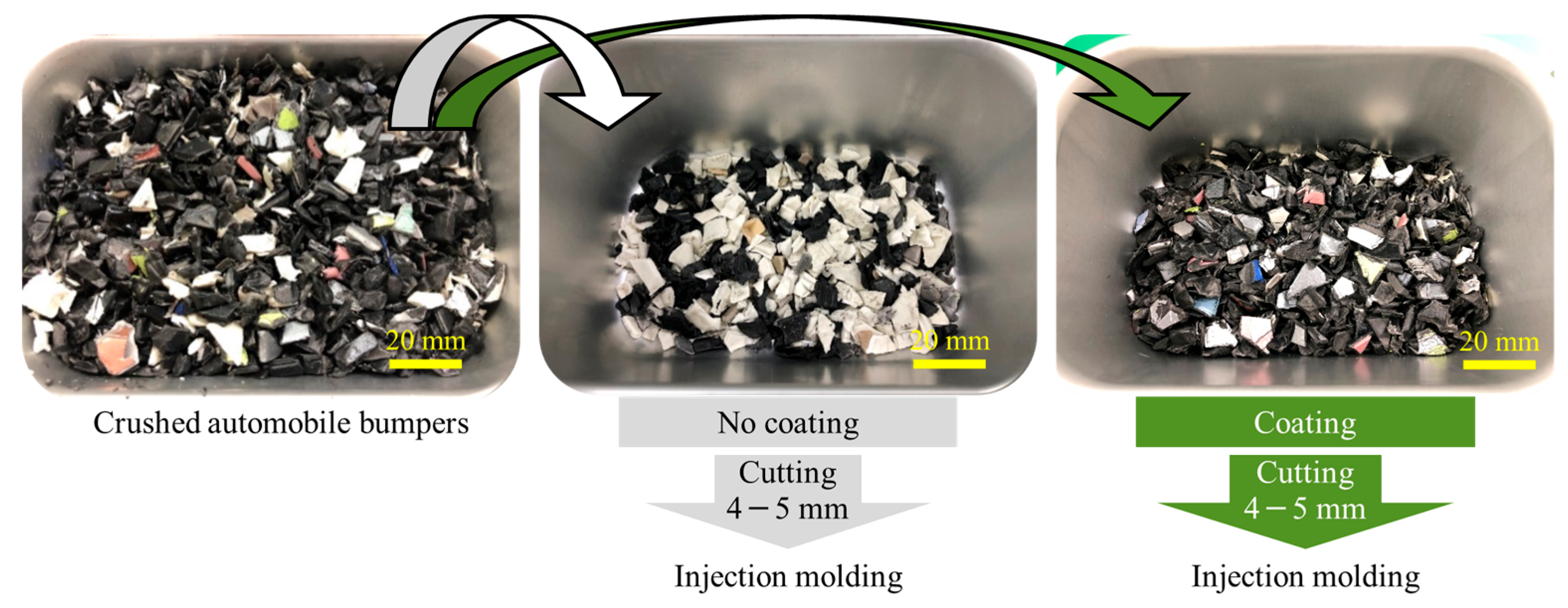
2.1. Materials
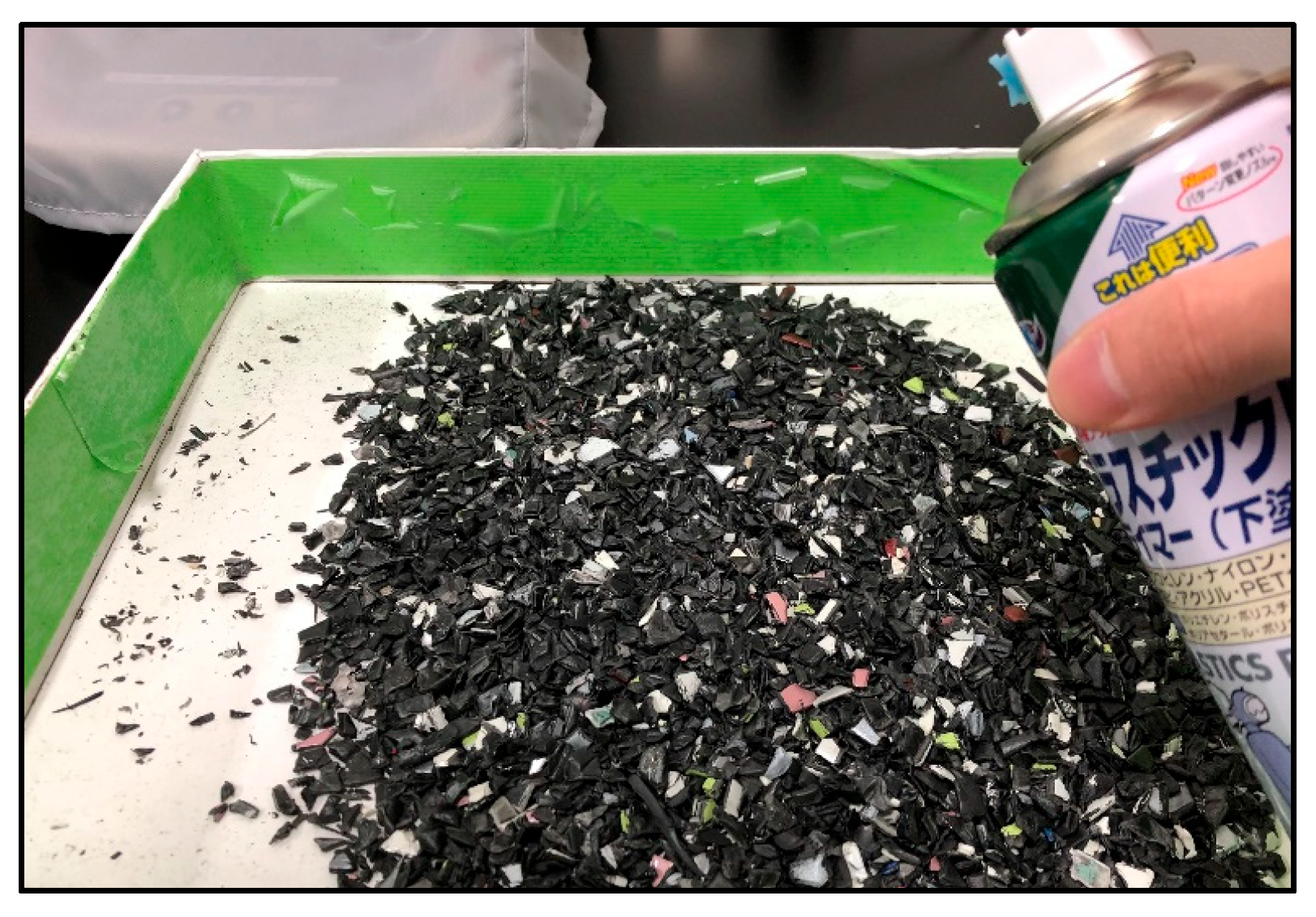
2.2. Primer Coating
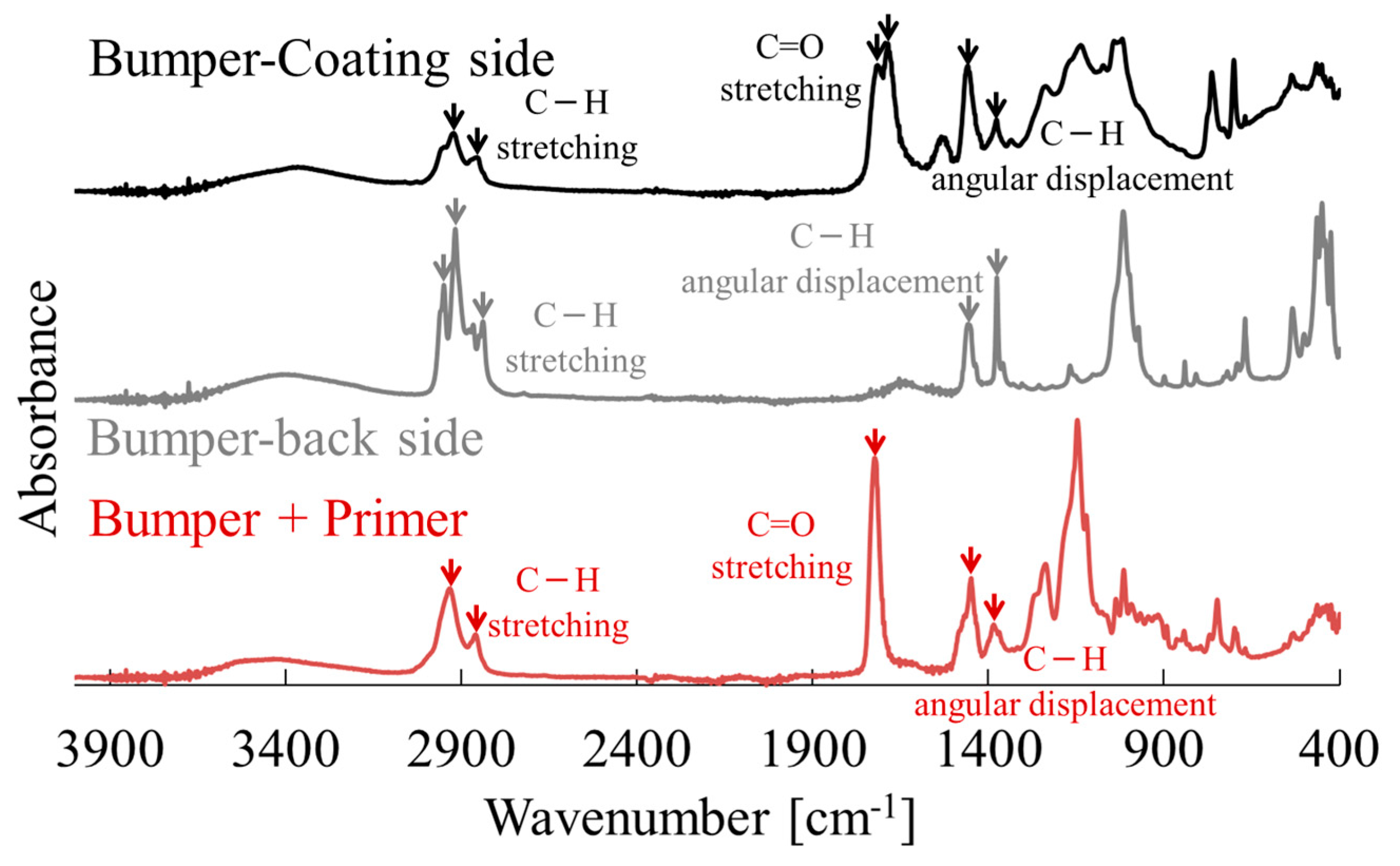
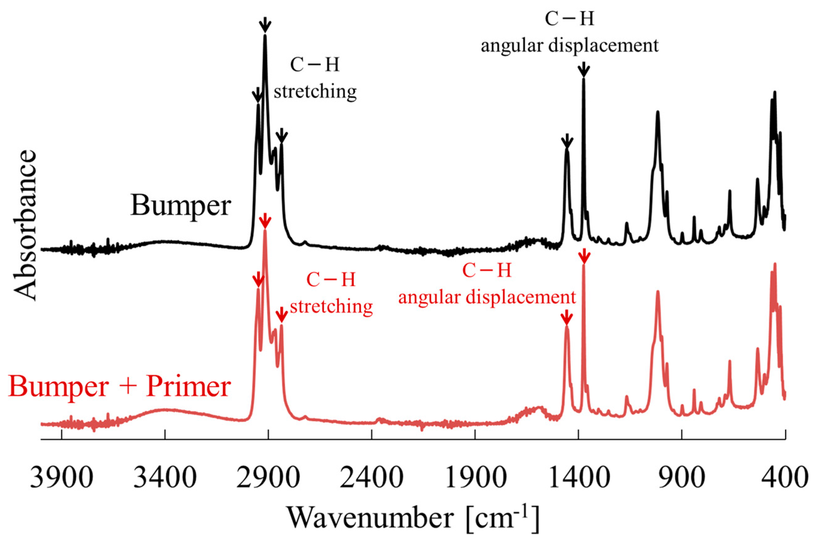
2.3. FT-IR Measurement
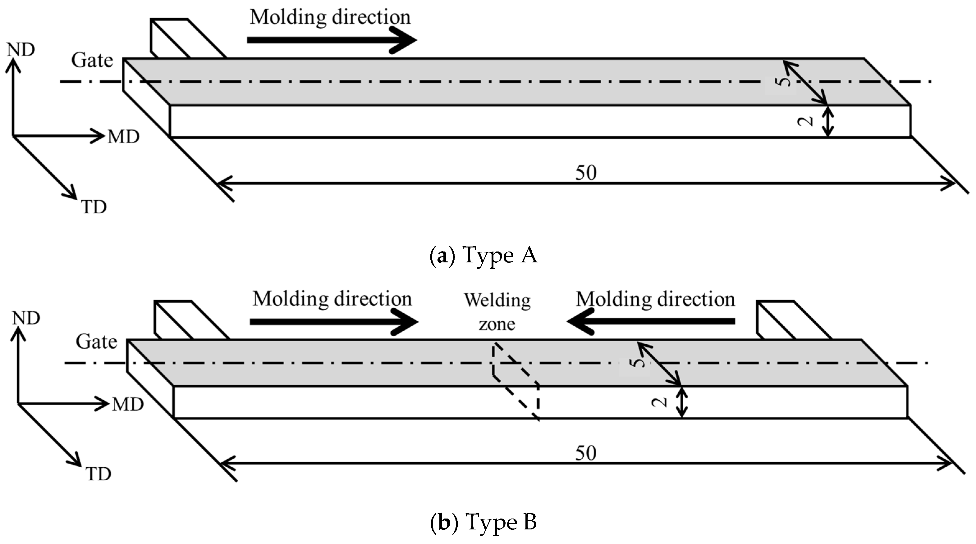
2.4. Injection Molding
2.5. Three-Point Bending Tests
2.6. Notched Charpy Impact Tests
2.7. Tensile Tests
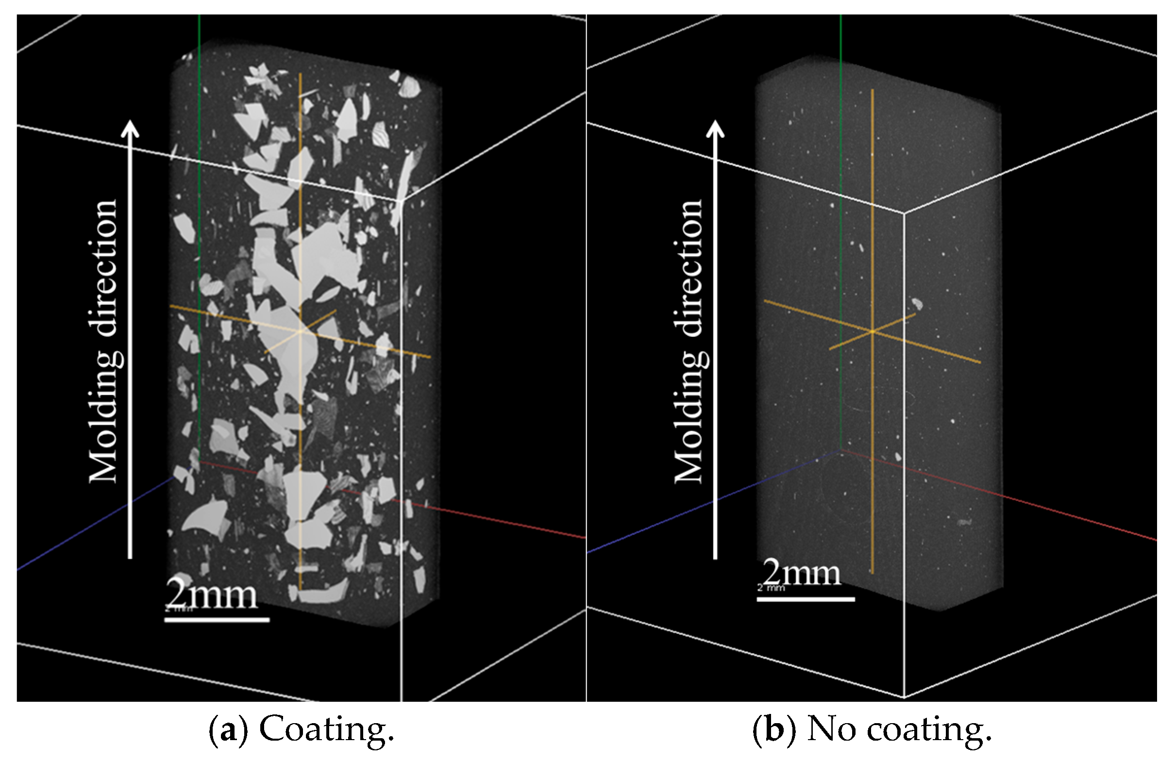
2.8. Microfocus X-Ray CT Observation
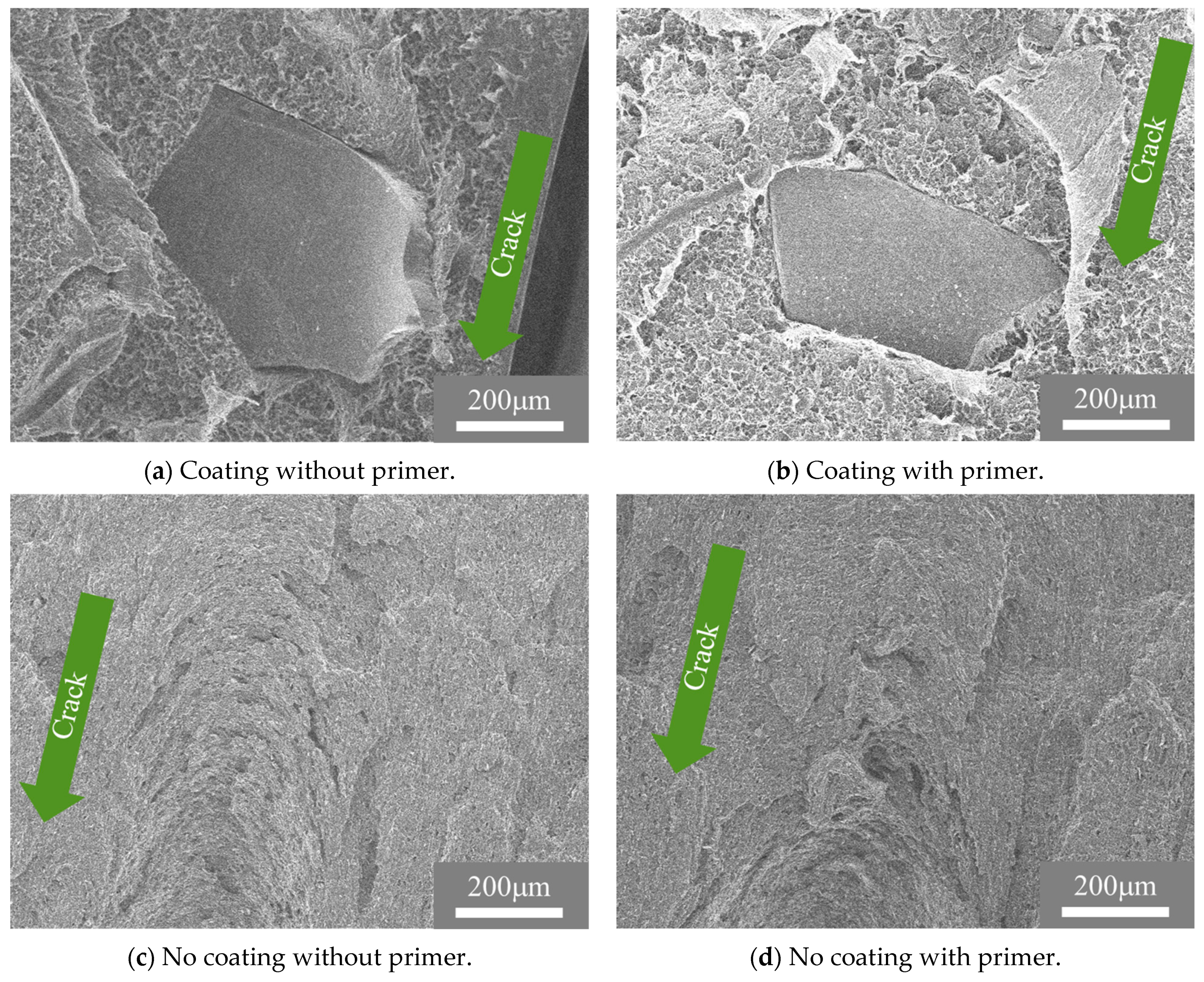
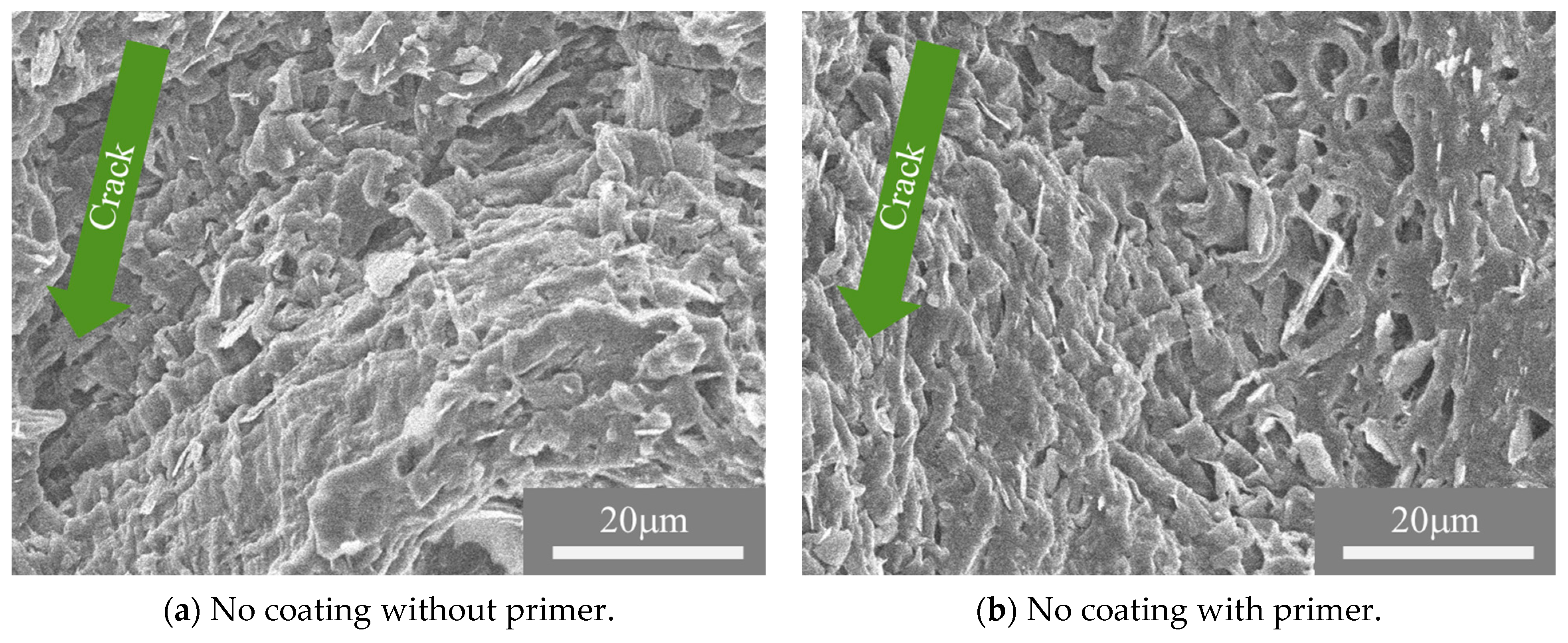
2.9. Scanning Electron Microscope Observation
3. Results
3.1. Coating and Primer Composition
3.2. Dispersion State of the Coating Film Inside the Molded Product
3.3. Effects of Primer Coating on Bending Properties and Impact Strength
3.4. Primer Coating Effect on Interfacial Strength
4. Discussion
4.1. Primer Coating Effects on Bending Properties of Injection-Molded Products
4.2. Primer Treatment Effects on Impact Fracture Properties of Injection-Molded Products
5. Conclusions
Author Contributions
Funding
Data Availability Statement
Conflicts of Interest
References
- MacArthur, E. The New Plastics Economy Rethinking the future of plastics. In World Economic Forum; Ellen Macarthur Foundation: Isle of Wight, UK, 2016. [Google Scholar]
- Jeong, C.B.; Won, E.J.; Kang, H.M.; Lee, M.C.; Hwang, D.S.; Hwang, U.K. Microplastic Size-Dependent Toxicity, Oxidative Stress Induction, and p-JNK and p-p38 Activation in the Monogonont Rotifer (Brachionus koreanus). Environ. Sci. Technol. 2016, 50, 8849–8857. [Google Scholar] [CrossRef]
- Tanaka, K.; Takada, H. Microplastic fragments and microbeads in digestive tracts of planktivorous fish from urban coastal waters. Sci. Rep. 2016, 6, 34351. [Google Scholar] [CrossRef] [PubMed]
- Lee, M.Y.; Cho, N.H.; Lee, S.J.; Um, N.; Jeon, T.W.; Kang, Y.Y. Application of material flow analysis for plastic waste management in the Republic of Korea. J. Environ. Manag. 2021, 299, 113625. [Google Scholar] [CrossRef] [PubMed]
- Salem, S.M.A. Influential parameters on natural weathering under harsh climatic conditions of mechanically recycled plastic film specimens. J. Environ. Manag. 2019, 230, 355–365. [Google Scholar] [CrossRef] [PubMed]
- Hajj, N.E.; Seif, S.; Zgheib, N. Recycling of poly(propylene)-based car bumpers as carrier resin for short glass fiber composites. J. Mater. Cycles Waste Manag. Dordr. 2021, 23, 288–300. [Google Scholar] [CrossRef]
- Czarnecka-Komorowska, D.; Kanciak, W.; Barczewski, M.; Barczewski, R.; Regulski, R.; Sedziak, D.; Jedryczka, C. Recycling of Plastics from Cable Waste from Automotive Industry in Poland as an Approach to the Circular Economy. Polymers 2021, 13, 3845. [Google Scholar] [CrossRef]
- Adekunle, A.S.; Adeleke, A.A.; Sam Obu, C.V.; Ikubanni, P.P.; Ibitoye, S.E.; Azeez, T.M. Recycling of plastics with compatibilizer as raw materials for the production of automobile bumper. Cogent Eng. 2020, 7, 1801247. [Google Scholar] [CrossRef]
- Deng, Y.; Dewil, R.; Appels, L.; Ansart, R.; Baeyens, J.; Kang, Q. Reviewing the thermo-chemical recycling of waste polyurethane foam. J. Environ. Manag. 2021, 278, 111527. [Google Scholar] [CrossRef]
- Eriksen, M.K.; Pivnenko, K.; Faraca, G.; Boldrin, A.; Astrup, T.F. Dynamic Material Flow Analysis of PET, PE, and PP Flows in Europe: Evaluation of the Potential for Circular Economy. Environ. Sci. Technol. 2020, 54, 16166–16175. [Google Scholar] [CrossRef]
- Jin, H.; Yu, J.; Okubo, K. Life cycle assessment on automotive bumper: Scenario analysis based on End-of-Life vehicle recycling system in Japan. Waste Manag. Res. J. A Sustain. Circ. Econ. 2021, 40, 765–774. [Google Scholar] [CrossRef]
- Liang, Y.; Tan, Q.; Song, Q.; Li, J. An analysis of the plastic waste trade and management in Asia. Waste Manag. 2021, 119, 242–253. [Google Scholar] [CrossRef] [PubMed]
- Kamo, T. Current Status of Waste Plastics and Issues for Recycling. J. Jpn. Assoc. Sustain. Based Co-Innov. Compet. 2021, 1, 28–44. [Google Scholar]
- Oblak, P.; Gonzalez-Gutierrez, J.; Zupancic, B.; Aulova, A. Processability and mechanical properties of extensively recycled high density polyethylene. Polym. Degrad. Stab. 2015, 114, 133–145. [Google Scholar] [CrossRef]
- Dorigato, A. Recycling of polymer blends. Adv. Ind. Eng. Polym. Res. 2021, 4, 53–69. [Google Scholar] [CrossRef]
- Demets, R.; Roosen, M.; Vandermeersch, L.; Ragaert, K.; Walgraeve, C.; De Meester, S.D. Development and application of an analytical method to quantify odour removal in plastic waste recycling processes. Resour. Conserv. Recycl. 2020, 161, 104907. [Google Scholar] [CrossRef]
- Yu, J.; Liu, X.; Manago, G.; Tanabe, T.; Osanai, S.; Okubo, K. New Terahertz Wave Sorting Technology to Improve Plastic Containers and Packaging Waste Recycling in Japan. Recycling 2022, 7, 66. [Google Scholar] [CrossRef]
- Okubo, K.; Manago, G.; Tanabe, T.; Yu, J.; Liu, X.; Sasaki, T. Identifying plastic materials in post-consumer food containers and packaging waste using terahertz spectroscopy and machine learning. Waste Manag. 2025, 196, 32–41. [Google Scholar] [CrossRef]
- Yada, K.; Moritomi, S. Trend of Technology and Development of Automotive PP Materials. Seikei-Kakou 2015, 27, 457–461. [Google Scholar] [CrossRef]
- Wyss, K.M.; De Kleine, R.D.; Couvreur, R.L.; Kiziltas, A.; Mielewski, D.F.; Tour, J.M. Upcycling end-of-life vehicle waste plastic into flash graphene. Commun. Eng. 2022, 1, 3. [Google Scholar] [CrossRef]
- Bodude, M.A.; Akano, T.T.; Owa, A.F. Mechanical and microstructural characterization of rubber particle reinforced thermoplastic for automobile bumper application. MANAS J. Eng. 2019, 7, 89–93. [Google Scholar]
- Rajasekaran, D.; Maji, P.K. Recycling of waste PP and crumb rubber together by use of self-healing ionomer as process compatibilizer. J. Mater. Cycles Waste Manag. 2021, 23, 1058–1070. [Google Scholar] [CrossRef]
- Ladhari, A.; Kucukpinar, E.; Stoll, H.; Sangerlaub, S. Comparison of Properties with Relevance for the Automotive Sector in Mechanically Recycled and Virgin Polypropylene. Recycling 2021, 6, 76. [Google Scholar] [CrossRef]
- Kumada, M. Recycle Technology for the Automotive Bumper. J. Surf. Finish. Soc. Jpn. 1997, 48, 154–158. [Google Scholar] [CrossRef]
- Sover, A.; Zink, M.; Michalak, M. Paint removal from thermoplastic materials and its influence on the physical–mechanical properties for the recycling of the polymer. IOP Conf. Ser. Mater. Sci. Eng. 2021, 1037, 012032. [Google Scholar] [CrossRef]
- Sover, A. Research on the Process of Paint Removal from Thermoplastic Materials by Laser. IOP Conf. Ser. Mater. Sci. Eng. 2019, 564, 012028. [Google Scholar] [CrossRef]
- ISO 178:2019; Plastics—Determination of Flexural Properties. The British Standards Institution: London, UK, 2019.
- ISO 179-1:2023; Plastics—Determination of Charpy Impact Properties Part 1: Non-Instrumented Impact Test. The British Standards Institution: London, UK, 2023.
- ISO 527-1:2019; Plastics—Determination of Tensile Properties—Part 1: General Principles. The British Standards Institution: London, UK, 2019.
- Takayama, T. Weld strength of injection molded short fiber reinforced polypropylene. Mech. Mater. 2019, 136, 103064. [Google Scholar] [CrossRef]
- Rosemal, M.; Haris, H.; Sathasivam, K.; Mohan, S. FT-IR and FT-Raman Spectra and Normal Coordinate Analysis of Poly methyl methacrylate. Der Pharma Chem. 2010, 2, 316–323. [Google Scholar]
- Abdel-Hamid, H.M. Effect of electron beam irradiation on polypropylene films—Dielectric and FT-IR studies. Solid-State Electron. 2005, 49, 1163–1167. [Google Scholar] [CrossRef]
- Takayama, T.; Kobayashi, S.; Yuasa, Y.; Jiang, Q. Effect of Carbon Nanofiber Distribution on Mechanical Properties of Injection-Molded Aramid-Fiber-Reinforced Polypropylene. Polymers 2024, 16, 1110. [Google Scholar] [CrossRef]
- Takayama, T.; Motoyama, Y. Injection molding temperature dependence of elastic coefficients obtained using three-point bending tests to ascertain thermoplastic polymer coefficients. Mech. Eng. J. 2021, 8, 20–00414. [Google Scholar] [CrossRef]


| Materials | Coating | Primer | σF [MPa] | EF [MPa] | aiN [kJ/m2] | Weld [MPa] |
|---|---|---|---|---|---|---|
| Bumper | Yes | No | 27.6 ± 0.1 | 1667 ± 27 | 25.4 ± 4.5 | 9.0 ± 0.5 |
| Yes | Yes | 29.2 ± 0.2 | 1761 ± 24 | 23.4 ± 4.0 | 10.1 ± 0.4 | |
| No | No | 25.0 ± 0.1 | 1523 ± 14 | 40.0 ± 4.4 | - | |
| No | Yes | 22.9 ± 0.4 | 1314 ± 45 | 73.6 ± 8.5 | - |
| Materials | Coating | Primer | υ [-] | E [MPa] | YS [MPa] |
|---|---|---|---|---|---|
| Bumper | No | No | 0.443 ± 0.001 | 451 ± 5 | 11.6 ± 0.1 |
| No | Yes | 0.444 ± 0.002 | 384 ± 13 | 10.6 ± 0.2 |
Disclaimer/Publisher’s Note: The statements, opinions and data contained in all publications are solely those of the individual author(s) and contributor(s) and not of MDPI and/or the editor(s). MDPI and/or the editor(s) disclaim responsibility for any injury to people or property resulting from any ideas, methods, instructions or products referred to in the content. |
© 2025 by the authors. Licensee MDPI, Basel, Switzerland. This article is an open access article distributed under the terms and conditions of the Creative Commons Attribution (CC BY) license (https://creativecommons.org/licenses/by/4.0/).
Share and Cite
Takayama, T.; Niiyama, T.; Tanabe, T.; Yu, J. Secondary Treatment Facilitating the Mechanical Recycling of Film-Coated Waste Automobile Bumpers. Recycling 2025, 10, 74. https://doi.org/10.3390/recycling10020074
Takayama T, Niiyama T, Tanabe T, Yu J. Secondary Treatment Facilitating the Mechanical Recycling of Film-Coated Waste Automobile Bumpers. Recycling. 2025; 10(2):74. https://doi.org/10.3390/recycling10020074
Chicago/Turabian StyleTakayama, Tetsuo, Toshiyuki Niiyama, Tadao Tanabe, and Jeongsoo Yu. 2025. "Secondary Treatment Facilitating the Mechanical Recycling of Film-Coated Waste Automobile Bumpers" Recycling 10, no. 2: 74. https://doi.org/10.3390/recycling10020074
APA StyleTakayama, T., Niiyama, T., Tanabe, T., & Yu, J. (2025). Secondary Treatment Facilitating the Mechanical Recycling of Film-Coated Waste Automobile Bumpers. Recycling, 10(2), 74. https://doi.org/10.3390/recycling10020074