Abstract
Effective and environmentally benign removal of polyvinylidene fluoride (PVDF) binders from spent battery electrodes remains a critical hurdle in sustainable recycling, primarily due to issues related to the mitigation of fluorinated compound emissions. This work evaluates PVDF binder removal from cathode active material using either a green solvent-based dissolution process or pyrolysis, analyzed by time-of-flight secondary ion mass spectrometry (ToF-SIMS). The solvent pretreatment involved mixing dihydrolevoglucosenone (Cyrene™) with PVDF-coated NMC811 at 100 °C, followed by hot filtration to separate the Cyrene-PVDF solution. Pyrolysis was conducted at 800 °C under an argon atmosphere. Positive ToF-SIMS spectra for Cyrene showed characteristic peaks at ketene (42 m/z) and 1,3-dioxole (86 m/z), along with intense C2H3O+, C3H3O+, C4H7+, and C3H5O+ peaks. The characteristic peaks used to identify PVDF were C3H2F5+ (133 m/z), C3H2F3+ (95 m/z), and C3HF4+ (113 m/z). Both processes resulted in PVDF removal, with pyrolysis demonstrating higher effectiveness. Particle agglomeration was observed in both pretreated NMC811 samples, however agglomeration was more pronounced with Cyrene pretreatment due to PVDF redeposition. Following pyrolysis, PVDF was transformed into a defluorinated carbonaceous material.
1. Introduction
The demand for lithium-ion batteries (LIBs) is rapidly increasing, a trend that is expected to continue for the foreseeable future [1]. One major concern faced by the battery industry is the increasing number of spent LIBs entering the recycling value chain, as they pose a risk to the environment and by extension our society [2]. As a result, much research has been conducted on different processing techniques that can be employed when recycling spent LIBs, these include direct recycling, hydrometallurgy and pyrometallurgy [3,4]. Pinegar and Smith [5] reviewed some of the most well-known commercial battery recycling processes, these include the Umicore, Inmetco, Glencore, Accurec, Retriev, Recupyl and EcoBat processes. Regardless of the processing technique chosen, there are a variety of processing stages that need to be employed to deal with the complex nature of battery material. Informative reviews [1,6] which thoroughly discuss the different processing stages that can be employed when recycling spent LIBs are also available. The choice of process is highly dependent on the chemistry of the spent batteries as some batteries are low value (lithium iron phosphate) while others hold significantly more value (nickel and cobalt based batteries), thus it is necessary to understand the market in which they are operating. A life cycle assessment also provides a good resource for better understanding the battery value chain, as such highlighted in the review article of Arshad and coworkers [3]. Finally, to understand the battery industry in an Australian context, the latest market data for the battery industry by Langdon and coworker [7], provided an overview by mapping of battery flows, including battery sales, batteries in use, and spent batteries collection and reprocessing, by battery chemistry, format or size and application.
Lithium-ion batteries contain several components that can negatively impact the environment, including perfluoroalkyl and polyfluoroalkyl substances (PFAS). Perfluoroalkyl and polyfluoroalkyl substances describe a large group of synthetic fluorinated organic compounds, which are chemically stable due to the presence of strong C-F bonds [8]. They are persistent chemicals meaning they do not degrade easily and thus accumulate in the environment [9].
The release of PFAS into the environment can result in devastating environmental, financial, and health implications for the surrounding communities (e.g., requires expensive environmental remediation, can damage the immune system, thyroid, and liver [9,10], particularly when the material is either in a soluble or in a micro-dispersed solid form, making these material highly mobile in the environment. The potential environmental and health risks linked with PFAS have prompted governing bodies like the European Commission to propose banning their usage. If successful, such legislation could be implemented as soon as 2026 [11], however, significant quantities of spent batteries would require safe recycling techniques.
Polyvinylidene fluoride (PVDF), is one such PFAS and has applications in a host of different industries, due to its good physical and chemical properties which make it resistant to chemical and thermal degradation [12,13]. Polyvinylidene fluoride is ideal to be used as a binder in LIBs as it allows for the strong adhesion of cathode active material (CAM) particles to the conductive Al foil and absorption of the electrolyte, thereby allowing for the transfer of lithium (Li) ions to the CAM material, and offering a high degree of electrochemical stability [1,12,14,15]. Water soluble binders such as carboxymethyl cellulose-styrene-butadiene rubber (CMC-SBR) offer alternatives to PFAS binders [14,16], however they are more likely applied to the anode electrodes.
The focus of this study is to compare the effectiveness of greener technologies (i.e., technologies that have a smaller environmental impact than current industrial technologies) in removing binders from cathode materials as found in nickel-manganese-cobalt (NMC) based lithium-ion batteries (LIBs), specifically PVDF as it is the state-of-the-art binder used in CAMs and some anodes [17].
During battery recycling, it is important to remove binders prior to any processing techniques as they can affect the recovery/separation efficiencies of processes such as flotation and leaching. In the case of froth flotation, binders alter the surface wettability of CAMs and anode active materials (AAMs, i.e., graphite), reducing their separation efficiency [18,19,20]. On the other hand, during leaching, the presence of PVDF on CAMs particles can impact the dissolution of target metals [21,22]. The PVDF binder adheres the CAMs to the Al foil and binds the individual CAM particles to one another resulting in the formation of agglomerates post crushing/shredding [23]. The decrease in the exposed CAM particle surface area leads to reductions in the leaching efficiencies of CAM.
Currently, two main strategies are employed to remove PVDF during LIBs recycling, namely thermal pretreatment or chemical dissolution [24]. In this context, thermal pretreatment describes a process that operates at elevated temperatures (400–600 °C) for the decomposition of an organic binder [17] and is typically performed under an inert atmosphere to prevent graphite oxidation. Pyrolysis is one of the most common thermal pretreatments employed to remove PVDF from spent LIBs/CAM and the decomposition of PVDF occurs at temperatures between 400 °C and 500 °C [17,25,26]. The main advantages of using pyrolysis include its effectiveness in removing PVDF [27] as well as the reduction in overall process complexity as spent batteries can be pyrolyzed without the need for a separate battery discharge stage, as typically seen when using hydrometallurgical routes [28]. However, there are numerous drawbacks, including the generation of toxic off-gases from the decomposition of PVDF and other organics [17]. Off-gases include halogenated hydrocarbons, hydrofluoric acid (HF), polynuclear organic substances and other toxic hydrocarbons [27,29,30], all of which are harmful to the environment and human and animal health. Scrubbing of the gases provides an “end-of-pipe” solution, but transfers many problems to liquid effluents that requires costly downstream treatment.
An alternative to pyrolysis is the dissolution of PVDF in dipolar aprotic solvents, the most common of which include dimethylacetamide (DMA), dimethylformamide (DMF) and N-methyl-2-pyrrolidone (NMP) [14,31]. These solvents are often toxic, adversely affect the human reproductive system and cause numerous health issues [32,33]. As such, the use of solvents such as NMP are strictly regulated [24]. Thus, many researchers are investigating greener solvents that can be used for PVDF dissolution.
Dihydrolevoglucosenone (refer to Figure 1), going by the commercial name of “Cyrene™”, shows promise in replacing the aforementioned solvents for PVDF dissolution [34,35,36]. Cyrene is a bio-derived dipolar aprotic solvent that is produced through the pyrolysis of cellulose, e.g., from agricultural and wood-derived wastes, producing levoglucosenone which is then hydrogenated, creating dihydrolevoglucosenone [33]. Cyrene has a high boiling point (227 °C), is miscible in water and thus offers a system in which the solvent polarity can be adjusted by altering the water to Cyrene ratio [31,33]. The advantages of using Cyrene, as opposed to conventional dipolar aprotic solvents, includes no significant toxicity, non-mutagenic, non-genotoxic, and readily biodegradable within 28 days [37].
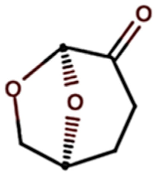
Figure 1.
Structure of dihydrolevoglucosenone (adapted from Sigma-Aldrich [37]).
Heating is essential for dissolving PVDF in Cyrene. Previous research [38,39] has demonstrated that temperatures exceeding 80 °C are necessary to achieve dissolution. Once dissolved, PVDF can be recovered through thermally induced phase separation (TIPS) as it precipitates from Cyrene upon cooling [36,38]. For battery recycling applications, it is crucial to consider Cyrene’s sensitivity to strongly oxidizing, reducing, acidic, or basic environments [33]. This is particularly relevant because metals like cobalt (Co) and nickel (Ni), commonly found in batteries, are strong reducing agents.
One of the most challenging aspects of the PVDF removal process is in the analysis of PVDF residuals in the CAM or black mass material (fine fraction from LIB comminution). Common analytical techniques such as inductively coupled plasma mass spectrometry (ICP-MS), energy dispersive X-ray spectroscopy (EDS), X-ray fluorescence spectroscopy (XRF), and X-ray diffraction spectroscopy (XRD) have trouble analysing light elements [40,41] and several of the above techniques (EDS, XRF, and ICP-MS) cannot be applied when analysing organic compounds.
Industrially, there was previously little incentive for companies to analyse residual PVDF, however as the EU tightens its regulations around PFAS materials, companies are becoming more interested in accounting for PVDF in their process streams. Currently, most of the research utilizes combinations of Fourier-transform infrared spectroscopy (FTIR), Raman spectroscopy, and EDS when trying to identify the extent to which PVDF is removed [38,42,43] as well as inductively coupled plasma optical emission spectroscopy (ICP-OES) to identify any deportment of lithium or other metal species during Cyrene pre-treatment [38]. The amount of fluorine in the sample before and after the pre-treatment can be analysed by quantitative EDS [24,38]). FTIR and Raman spectroscopy can be used to identify the presence of PVDF in a sample as well as provide insight into the structure of PVDF [38,43].
Time-of-flight secondary ion mass spectrometry (ToF-SIMS) is a surface-sensitive analytical technique capable of detecting light elements, trace elements, and organic compounds. Sui and co-workers [40] investigated the analysis of battery materials using a combination of ToF-SIMS and focused ion beam —scanning electron microscope (FIB-SEM) to perform nano-scale chemical mapping on LIB CAM and analysis on the mobility or lack thereof of elements such as Li, Co and Mn during the charging and discharging of LIBs.
To the best of authors’ knowledge, ToF-SIMS has not been used to qualitatively evaluate the removal of PVDF during LIB recycling through pyrolysis and Cyrene-based pre-treatment techniques. The sensitivity of the technique, coupled with the ability to produce high spatial-resolution chemical/molecular maps makes ToF-SIMS a suitable analysis technique for detecting light elements and organic binders in battery materials. The aim of this research is to investigate the removal of PVDF through either Cyrene or pyrolysis pretreatments. Using ToF-SIMS, this research also aims to identify the unique spectra of pristine Cyrene and PVDF, which can then be applied to identify their presence in battery materials. Techniques such as Raman spectroscopy, FTIR, and SEM are used to support the ToF-SIMS findings.
2. Methods & Materials
2.1. Materials
Various battery materials were studied to determine the presence and removal of PVDF on battery materials namely, pristine CAM without PVDF—NMC 111 (LiNi0.33Mn0.33Co0.33O2, MSE supplies, Product No. PO0126), PVDF-coated CAM—NMC 811 (PVDF—LiNi0.8Mn0.1Co0.1O2, Targray, Lot No. NMC 811-003T) and battery grade PVDF (≥99.6%, MSE supplies, batch No. 22420A2, Tucson, AZ, USA). Cyrene solvent (99.3% dihdyrolevoglucosenone, batch no. DCyD12_220308) with a purity of 99.28% was supplied by the Circa Group, Melbourne, Australia.
2.2. Methods
2.2.1. PVDF Dissolution—Cyrene Pretreatment Experiments
The dissolution of PVDF was initially investigated by dissolving 0.5 g pure PVDF into 20 mL Cyrene at 100 °C. Figure 2 depicts a simple Cyrene-PVDF dissolution experiment which involved mixing PVDF powder with Cyrene at room temperature (A), heating the mixture to 100 °C and achieving complete PVDF dissolution (B) and cooling the solution to 50 °C, resulting in the formation of a gel-like material (C). The room temperature Cyrene-PVDF mixture (D) was centrifuged to recover a single lump of PVDF (E).
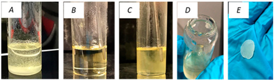
Figure 2.
PVDF dissolution with Cyrene: Cyrene-PVDF mixture at room temperature, (A) heated solution at 100 °C (B), mixture cooled at 53 °C (C), mixture at room temperature (D), and recovered PVDF after centrifugation of mixture at room temperature (E).
To determine the effect of Cyrene pretreatment at elevated temperatures on pristine CAM, 5 g NMC 111 and 30 mL Cyrene were mixed, heated, and held at 100 °C for 1 h. The heated NMC 111-Cyrene mixture was separated by a heated vacuum filtration using a filter paper (Whatman®, GE Healthcare Companies, Chicago, IL, USA) with a pore size of 11 µm. Heated filtration was achieved by placing a typical Büchner funnel filtration set up into a drying oven at 100 °C. To investigate the removal of PVDF from CAM, 5 g of NMC 811 coated with PVDF was contacted with 30 mL of Cyrene following the procedure above. If no heated filtration was used, the Cyrene-PVDF solution was observed to be more viscous than pure Cyrene, leading to a longer filtration time. This causes cooling of the solution to temperatures below 80 °C. After filtration, the Cyrene-PVDF solution was cooled down to room temperature, after which the mixture was vacuum-filtered or centrifuged to recover PVDF.
2.2.2. PVDF Removal—Pyrolysis Pretreatment Experiments
Pyrolysis pretreatment was simulated using thermogravimetric analysis (TGA) equipment. Approximately 30 mg of PVDF-coated NMC 811 was loaded into an alumina crucible and heated to 800 °C. The samples were held at 800 °C for 5 min, ensuring that enough time was given for PVDF decomposition.
The above pre-treatments of pristine materials resulted in the production of: two NMC 111 samples: no pretreatment and pretreated with Cyrene. Along with, four NMC 811 samples, two of which were treated identically to the NMC 111 above, however the third sample was washed post-filtration, and the fourth sample underwent a simulated pyrolysis pretreatment. Figure S1 in the Supplementary Material presents detailed process flow diagrams that describe the preparation of each material examined in this research.
2.3. Analytical Techniques
2.3.1. Scanning Electron Microscope (SEM)
The surface morphologies of the pristine, Cyrene pretreated, and pyrolysed CAM were characterized using SEM. The loose powder samples were mounted on aluminium stubs using double-sided carbon tape (PELCO Tabs TM, 6 mm OD from TED PELLA, Inc., Redding, CA, USA). Two SEMs were used, namely the TESCAN LYRA3 field emission SEM (Tescan, Brno, Czech Republic) at the John de Laeter Centre (JdLC), Curtin University, Perth, Australia and the FEI Quanta 600 F SEM (FEI, Hillsboro, OR, USA) at the Helmholtz Institute Freiberg for Resource Technology (HIF), Dresden, Germany. False colour images were produced at HIF by superimposing the secondary and backscattered electron (BSE) images. The BSE image provides information pertaining to material composition (variations in densities), with blue representing elements with high densities (i.e., Ni, Co, Mn) and black colouring the lighter elements such as carbon. The SE image provides topographical information of the analysed surface and has been given an orange colour.
2.3.2. Thermogravimetric Analyser (TGA)
TGA was performed on PVDF and PVDF-coated NMC 811 to determine the decomposition temperature of PVDF. Pyrolysis was simulated using TGA, namely the Mettler Toledo TCA/DSC 1 STAR System, Chicago, IL, USA. 25–30 mg samples were weighed out into platinum crucibles and were heated from 35 °C to 800 °C at a rate of 10 K/min in an argon atmosphere (gas flow rate = 25 mL/min). The samples were held at 800 °C for 5 min, after which they were cooled down to 35 °C at a rate of 10 K/min.
2.3.3. Fourier-Transform Infrared Spectroscopy (FTIR)
FTIR spectroscopy was used to identify the presence of PVDF in both the untreated and Cyrene-pretreated CAM as well as to determine any changes in PVDF and Cyrene (chemical or thermal) during the pretreatment process. A PerkinElmer Springfield the United States Spectrum 100 FT-IR Spectrometer (PerkinElmer, Waltham, MA, USA) with a diamond/ZnSe crystal was used and the analysis was conducted over a wavelength range of 600–4000 cm−1 with a resolution of 4 cm−1.
2.3.4. Raman Spectroscopy
Raman spectroscopy was used to determine if Cyrene post-PVDF dissolution contained residual PVDF or if Cyrene or PVDF underwent any chemical or thermal degradation during the pretreatment. The analysis was conducted using a LabRam HR 800 confocal Raman microscope HORIBA France SAS, Palaiseau, France and the spectra were interpreted and analysed using LabSpec5. The excitation wavelength of the laser was 632.817 nm at a laser intensity of 2 mW, a spectrometer grating of 600/mm was used and spectra from Raman shifts of 200 cm−1 to 3500 cm−1 were acquired. The lens used was at a 10× magnification (NA of 0.25) and the spectra were recorded with 5 s exposures and 5 repetitions.
2.3.5. Time-of-Flight Secondary Ion Mass Spectrometry (ToF-SIMS)
ToF-SIMS was used to investigate the surface of the CAM particles in order to characterise organic materials and map their spatial distribution. Prior to ToF-SIMS analysis, the powdered samples were pressed into pellets. The powder was loaded into a pellet dye and then pressed at 2000 kg for 1 min using the 5T electric press (model YLJ-5TA, KJ MTI Group, St Richmond, CA, USA). The final pellets had a diameter of approximately 5.5 mm and a thickness of 0.5 mm.
The ToF-SIMS analyses were carried out on a M6 instrument (IONTOF GmbH, Münster, Germany) at the JdLC. The instrument was operated in Spectrometry mode with a 30 kV Bi3+ primary ion source at a pulsed current of 0.06–0.14 pA. Positive ions were collected using High Mass Resolution mode for the mass analyser at a cycle time of 100 µs. The analytical conditions resulted in a lateral resolution of ~3 µm and a mass resolution of >10,000 M/ΔM. A random primary ion beam raster pattern and an electron flood gun was used to minimise charging effects during the analysis. SIMS maps were collected over a 50 to 200 µm field of view with 128 × 128 pixels in each frame. The mass spectra included all masses up to 250 mass/charge ratio. To remove surface contamination, the field of view was pre-sputtered with a Ar2000+ cluster ion source (10 kV, 8 nA) over a 500 × 500 µm area for 30 s. Data were analysed with Surface Lab version 7.3.
3. Results and Discussion
3.1. Pure PVDF Dissolution
The dissolution experiment demonstrated the ability of Cyrene to dissolve PVDF at elevated temperatures and the recovery of PVDF from solution upon cooling, which is consistent with the findings of previous research [38,39]. The recovered solution and solid were analysed using Raman spectroscopy to determine whether the Cyrene (post-PVDF dissolution) contained residual PVDF or underwent any changes (i.e., chemical or thermal degradation). The characteristic Raman shifts for different PVDF phases are: α-phases (410, 489, 611/612, 795) cm−1, β-phase (839 cm−1) and γ-phase (874 cm−1) [42,43].
Figure 3A shows a comparison between the Raman shifts obtained from a pure PVDF sample to that of Cyrene post-PVDF dissolution. These results illustrate that no PVDF is detected in the spent Cyrene solvent, suggesting that there is no build-up of PVDF in the Cyrene solvent. To confirm that Cyrene did not undergo any chemical or thermal degradation, a comparison of the Raman shifts for pure Cyrene and Cyrene post-PVDF dissolution are shown in Figure 3B. It was observed that peaks in the fingerprint region (300–1900 cm−1) are retained, and no new peaks appeared, implying that Cyrene did not undergo chemical or thermal degradation on the basis of this analysis. However, a minimal shift to higher energies after PVDF removal is observed in the peaks which can be explained by a change in molecular strains and stresses, as a result of heating Cyrene to 100 °C.
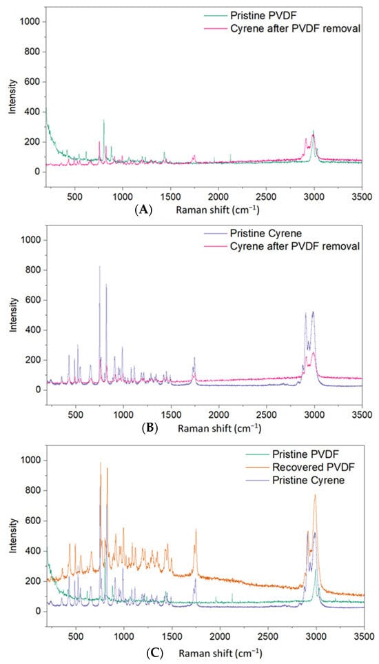
Figure 3.
Raman spectra of pristine PVDF and recovered Cyrene after PVDF dissolution (A), pristine Cyrene and recovered Cyrene (B), and pristine Cyrene and PVDF and recovered PVDF (C).
The above results allude to the possibility of recycling Cyrene as there is no build-up of PVDF in solution and no chemical/thermal degradation. Raman analysis on the recovered PVDF (Figure 3C) shows similar Raman peaks, however residual amounts of Cyrene were retained. This is most likely due to the high viscosity of Cyrene, making it difficult to completely remove through centrifugation. The high boiling point of Cyrene (227 °C) also requires elevated temperatures to completely remove Cyrene from PVDF. Thus, any PVDF recovered through this process should be washed thoroughly with water to remove residual Cyrene.
3.2. Cyrene Solvent Treatment
All reported solvents and diluents of PVDF fall under the dipolar aprotic category [36]. Cyrene, a dipolar aprotic solvent, is theoretically capable of dissolving PVDF. The Hansen solubility parameters of Cyrene (dispersion δD: 18.8; polar δp: 10.6; and hydrogen bonding δH: 6.9) are nearly identical to those of the conventional solvent NMP (δD: 18.0; δp: 12.3; and δH: 7.2) [36], suggesting that Cyrene should be able to dissolve PVDF under specific conditions. However, some research [35] has highlighted that the solubility of PVDF can vary significantly with molecular weight. More so, the higher viscosity of the Cyrene-PVDF solution likely played a critical role. It has been reported [44] that a PVDF-Cyrene solution exhibited a high viscosity of 810 mPa·s. As a comparison, PVDF at 10% w/v in NMP has viscosities of 120 mPa·s (Mw = 2.7 × 10⁵ g/mol) or 350 mPa·s (Mw = 4.4 × 10⁵ g/mol).
The high viscosity negatively impacted filtration, consequently hindering the separation of the Cyrene-PVDF solution from NMC 811. This led to extended filtration times and cooling of the solution below 80 °C, triggering thermally induced phase separation (TIPS) of PVDF and thus resulted in the non-selective redeposition of PVDF onto the NMC particles. Hot water (100 °C) was added to aid filtration. Figure 4A presents a false-coloured SEM image of pristine NMC 811 particles in comparison with those post-Cyrene pretreatment in Figure 4B,C. In these images, blue particles represent NMC 811, while dark gray material indicates PVDF coating. Figure 4A shows minimal particle agglomeration in the untreated material, with agglomerate sizes not exceeding 50–100 μm. However, Figure 4B–D demonstrate a significant increase in agglomeration post-Cyrene pretreatment, with agglomerates reaching up to 500 μm. This increased agglomeration is attributed to PVDF redeposition during filtration.
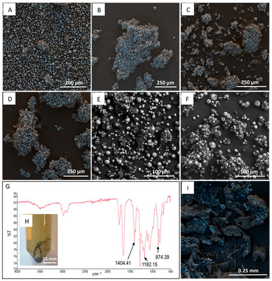
Figure 4.
SEM images of NMC and PVDF material. NMC 811 coated with PVDF (A), NMC 811 post Cyrene pretreatment (only washing with 100 °C water) (B–D), SEM-BSE of NMC 811 post Cyrene pretreatment (E,F), FTIR spectra of PVDF recovered from Cyrene solution (G). Cyrene-water solution and recovered PVDF (H). SEM image of recovered PVDF (I).
To mitigate PVDF redeposition, hot filtration was performed in an oven. The results are presented in the SEM-BSE images of Figure 4E,F. In these images, lighter (white) particles represent NMC 811, and dark gray regions indicate PVDF. Figure 4E, F, similar to Figure 4A, exhibit particle agglomeration with a maximum agglomerate size of 50–150 μm, demonstrating a significant reduction in agglomeration compared to the non-heated filtration (Figure 4B–D).
Upon cooling the Cyrene-water filtrate to room temperature, a polymer-like material formed (Figure 4H). The SEM image in Figure 4I revealed the presence of fine NMC 811 particles within this material. This contamination can be minimized by using filter paper with a smaller pore size, albeit at the cost of slower filtration rates. The FTIR spectrum in Figure 4G confirmed the material’s composition as PVDF, showing three characteristic peaks at 874, 1182, and 1404 cm−1. These peaks, although slightly shifted, confirm partial PVDF removal.
3.3. ToF-SIMS Base Spectra for Cyrene and PVDF
ToF-SIMS was used to characterise both the organic and inorganic components/molecules present in the samples. Molecules fragment during the SIMS ionisation process and as such the resultant mass spectra contains a series of characteristic peaks from the parent and fragment ions. In order to identify the presence of PVDF ((C2H2F2)n) and Cyrene (C6H8O3) in CAM, pristine materials were first analysed to determine the characteristic ions. This is illustrated in Figure 5A where the positive ToF-SIMS spectra for PVDF are provided. According to Feng et al. [45], PVDF fragments into carbon-containing molecules with 1, 2 or at most 3 carbon atoms. Feng and co-workers identified C3H2F5+ (133 m/z) as a characteristic PVDF peak along with several fluorinated peaks, some of which are present in Figure 5A. In this research, the characteristic C3H2F5+ peak at 133 m/z along with two other larger fluorinated molecules, namely C3H2F3+ (95 m/z) and C3HF4+ (113 m/z) were used to identify PVDF.
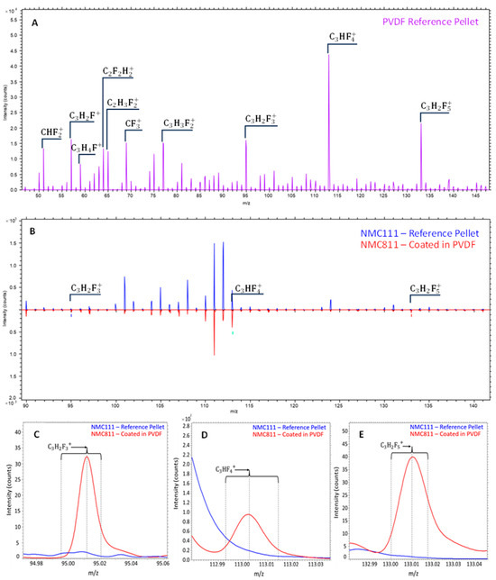
Figure 5.
Positive ToF-SIMS spectra of PVDF (A), comparison of the spectra for NMC 111 and NMC 811 coated in PVDF (B), and characteristic PVDF peaks from Figure 4B (C–E).
To confirm whether the PVDF peaks identified above could be detected in a battery material, the positive ToF-SIMS spectra from pristine NMC 111 and PVDF-coated NMC 811 powders were compared. As expected, the only difference between NMC 811 and 111 would be the peak intensities for the different metals as well as the PVDF peaks. Figure 5B shows that the base NMC spectra are almost identical, with only varying metal intensities due to different metal concentrations. The spectra for the PVDF-coated NMC 811 contains extra peaks including those of the three heavier fluorinated compounds mentioned above (see Figure 5C–E), confirming the capabilities of ToF-SIMS in detecting PVDF coatings in battery materials.
The positive ToF-SIMS spectra for Cyrene were also determined, which to the best of our knowledge had not yet been reported in literature. Liu et al. [46] proposed that when Cyrene molecule is hit by an electron beam during electron impact mass spectrometry (EI-MS), it fragments into smaller molecules, namely ketene (42 m/z), 2-methylene-1,3-dioxole (84 m/z), 2-methylene-1,3-dioxolane (85 m/z), and 1,3-dioxole (86 m/z). When analysing Cyrene with ToF-SIMS, similar compounds to those found by Liu and coworkers [46] were identified. For the analysis, Cyrene in liquid form was applied to silicon wafers and placed into a vacuum chamber to determine its stability under vacuum. After two days, the excess liquid was subsequently removed to obtain a thin layer of Cyrene on the silicon wafer. Figure 6A presents the positive ToF-SIMS spectra for Cyrene, the ketene (42 m/z) and 1,3-dioxole (86 m/z) molecules were detected along with intense C2H3O+, C3H3O+, C4H7+ and C3H5O+ peaks which is well comparable to the fragmentation patterns from EI-MS [46].
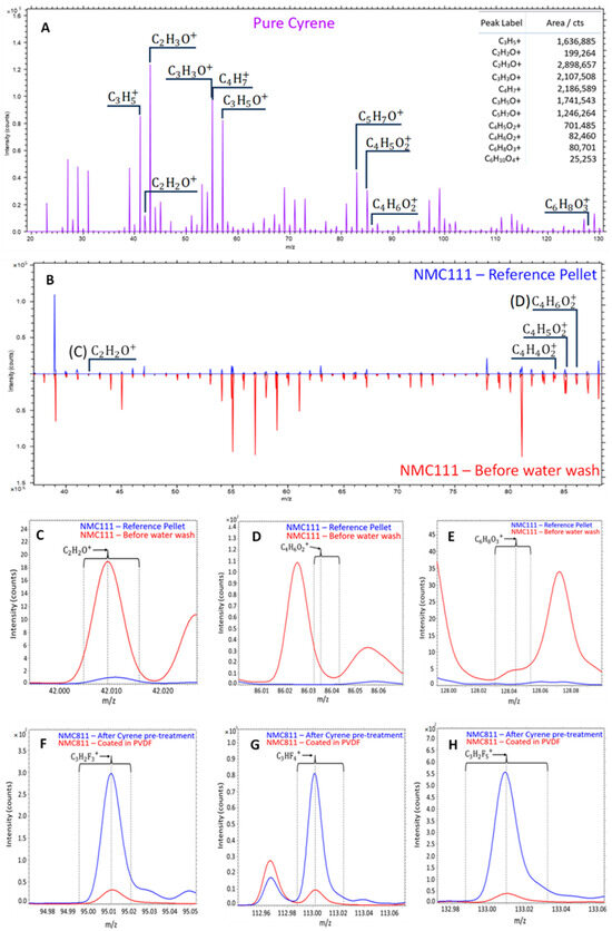
Figure 6.
Positive ToF-SIMS spectra of Cyrene (A), comparison of the spectra for NMC 111 and Cyrene washed NMC 111 (B), characteristic Cyrene peaks from Figure 5B (C–E), and characteristic PVDF peaks after Cyrene pretreatment of NMC811 (F–H).
A molecule with a m/z of 146 (higher than that of Cyrene) was also noted and identified as a hydrated Cyrene molecule with the formula C6H10O4 (Cyrene—C6H8O3). Further investigations around the heavier molecules will be conducted as this will shed light on possible compounds/chains that Cyrene may form. Due to Cyrene’s low volatility and high viscosity, its presence on the surface of CAMs after exposure/contact is also investigated. Figure 5B compares the spectra for pristine NMC111 to that of NMC111 soaked in Cyrene. This comparison illustrates (see Figure 5C,D) that ketene (42 m/z) and 1,3-dioxole (86 m/z) were detected on the surface of NMC111, showing that ToF-SIMS can be used when identifying Cyrene in battery materials.
3.4. ToF-SIMS as a Technique for Process Evaluation
Positive ToF-SIMS spectra (Figure 5A and Figure 6A) were used to verify Cyrene or pyrolysis as methods for PVDF removal. Contrary to expectations, the intensity of PVDF peaks was higher after Cyrene pretreatment (Figure 6F–H). Two possible explanations exist for this increase. First, the SIMS matrix effect, where secondary ion intensity depends on both element/molecule concentration and material composition. Second, and more likely, PVDF redeposition onto particle surfaces, as demonstrated in the pure PVDF dissolution experiments showing PVDF segregation from Cyrene below 80 °C. Figure 7A–C show substantial PVDF presence post-Cyrene pretreatment. PVDF redeposition results in particle agglomeration (Figure 4B–D). Uncontrolled PVDF redeposition during cooling leads to thick coatings, unlike those applied by cell manufacturers, resulting in higher PVDF readings. Figure 7C visually demonstrates this, showing a ~4 µm NMC particle coated by ~4 µm of PVDF. To confirm these coatings as PVDF, Figure 7D presents a chemical mapping using ToF-SIMS peak information, with green areas representing Li (NMC 811) and red areas shows C3H4F+, representing PVDF.
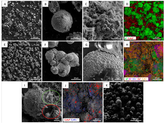
Figure 7.
SEM and ToF-SIMS chemical mapping of the treated battery materials. Cyrene pretreated NMC 811 (A–C), ToF-SIMS chemical mapping of Cyrene pretreated NMC 811 (D), pyrolyzed NMC 811 samples (E–G), ToF-SIMS chemical mapping of pyrolyzed NMC 811 (H), NMC 811 particle after pyrolysis (I), chemical mapping of the characteristic PVDF peaks after pyrolysis (J) and residue from PVDF pyrolysis at 800 °C (K).
While ToF-SIMS is limited in providing quantitative PVDF or Cyrene concentrations, it can qualitatively indicate pretreatment effectiveness. ToF-SIMS analysis of pyrolyzed samples (Figure S2) showed minimal PVDF peak intensities, suggesting low residual PVDF. ToF-SIMS chemical mapping (Figure 7H) of pyrolyzed material revealed C4H7+, consistent with de-fluorination. SEM imaging (Figure 7I) visualized organic matter distribution in pyrolyzed samples, revealing two regions on NMC 811 particles. The red zone, likely organic residue from PVDF decomposition, and the green region, likely residual PVDF (Figure 7J). Chemical mapping (Figure 7J) identified traces of fluorinated hydrocarbons C3H4F+ and C3HF4+, characteristics of PVDF. Li et al. [47] reported incomplete PVDF pyrolysis, with up to 26% residual mass, consistent with the 29% residue observed in TGA at 800 °C (Figure S3). SEM imaging (Figure 7K) showed that pyrolyzed PVDF particles retained their spherical shape, suggesting minimal change in residual PVDF on NMC 811. Pyrolyzed residue exhibited a melt texture (Figure 7G), binding NMC 811 particles and causing ~100 µm agglomerates. This carbonaceous coating may alter surface properties affecting subsequent recycling processes such as froth flotation.
Comparing Figure 7D,J, pyrolysis demonstrates substantially less PVDF than Cyrene pretreatment. Thus, pyrolysis is currently more effective. However, Cyrene solvent pretreatment is yet to be optimized, and thus it remains a promising technique for PVDF removal.
4. Conclusions
The recycling of spent LIBs presents a significant challenge in dealing with PVDF binder, which hinders particle liberation and alters the surface properties of active materials. Methods like thermal treatment and solvent-based techniques are commonly used to remove the PVDF binder. However, accurately quantifying their efficiency for binder removal using conventional analytical tools has remained a challenge. In response to this, this study utilised ToF-SIMS to produce high spatial-resolution chemical maps of cathodic material, offering a detailed insight into the distribution of PVDF within CAM. The positive ToF-SIMS characteristic peaks for Cyrene and PVDF were also identified. Cyrene had two characteristic peaks, namely ketene (42 m/z) and 1,3-dioxole (86 m/z) along with intense C2H3O+, C3H3O+, C4H7+ and C3H5O+ peaks. While the characteristic peaks for PVDF were identified to be C3H2F5+ (133 m/z), C3H2F3+ (95 m/z) and C3HF4+ (113 m/z).
The SEM and ToF-SIMS analysis concluded that both the Cyrene and pyrolysis pretreatments remove PVDF. However, both techniques do not fully remove the binder and lead to some degree of particle agglomeration. When using Cyrene pretreatment, the PVDF redeposited onto the CAM, resulting in thick layers of PVDF on the particle surfaces and large amounts of particle agglomeration. It was determined that the amount of PVDF redeposition could be minimized using hot filtration (>100 °C). After dissolution of pristine PVDF with Cyrene, both the recovered PVDF and spent Cyrene showed no residual PVDF in the Cyrene (post cooling). The recovered PVDF only contained some excess Cyrene which in theory can be removed through water rinsing. On the other hand when the CAM is pyrolyzed, a large amount of the PVDF decomposed (producing toxic halogenated hydrocarbons), leaving behind a carbonaceous material, that still binds the CAM particles to one another.
As of our current understanding, thermal treatment (i.e., pyrolysis) stands out as the most effective method for removing PVDF from CAMs. Nonetheless, this research has unveiled a promising alternative: the solvent-pretreatment of CAM with Cyrene, followed by a hot filtration process to separate the Cyrene-PVDF solution. It is crucial to underscore the substantial potential of the Cyrene pretreatment method. Through optimization of the operating parameters, Cyrene pretreatment could become a competitive alternative to pyrolysis, particularly when considering its ability to recover PVDF in an unaltered state and the elimination of harmful halogenated hydrocarbons as a waste product.
Supplementary Materials
The following supporting information can be downloaded at: https://www.mdpi.com/article/10.3390/recycling10020056/s1. Figure S1. Process flow diagrams for pre-treatment of PVDF (A), and NMC 111 and PVDF-coated NMC 811 (B). Figure S2. Comparison of positive ToF-SIMS spectra for NMC 811 post Cyrene and pyrolysis pretreatments (A). Enlarged images around characteristic PVDF peaks (B–D). Figure S3. TGA curve of pristine PVDF, 800 °C under Ar atmosphere at a heating rate of 10 K/min.
Author Contributions
Conceptualization, J.E. and A.V.; Methodology, M.S.H., A.M.S., W.D.A.R. and A.V.; Validation A.M.S. and M.S.H.; Formal Analysis, ToF-SIMS was performed by W.D.A.R.; Raman Spectroscopy was conducted by M.R. and SEM imaging was conducted by A.V., A.M.S. and M.S.H.; Investigation, M.S.H., A.M.S. and Á.J.R.M.; Resources, J.E. and M.R.; Data Curation, A.M.S. and M.S.H.; Writing—original draft preparation, M.S.H. and A.M.S. and A.V.; Writing—Review and Editing, M.S.H., A.M.S., A.V., C.C.B., J.E., M.R., E.A.O., W.D.A.R. and D.F.; Data Visualization, M.S.H., A.M.S., A.V. and W.D.A.R.; Supervision, A.V, J.E., M.R., E.A.O. and C.C.B.; Project Administration, A.V., J.E., M.R., E.A.O. and C.C.B.; Funding Acquisition, A.V., J.E. and M.R. All authors have read and agreed to the published version of the manuscript.
Funding
The RES-65109 RESTORE Project (Sustainable Recycling and Recovery of Electrode Materials from Spent lithium-ion Batteries) has been funded by the Future Battery Industries CRC (FBI-CRC, as part of the Australian Government Cooperative Research Centres Program) and the Universities Australia Deutscher Akademischer Austauschdienst (AU-DAAD). Curtin University and the Helmholtz Zentrum Dresden Rossendorf contributed to staff salaries and fee scholarships (for Mr Henderson). The IONTOF M6 ToF-SIMS at the JdLC, Curtin University, was obtained using funding from the Australian Research Council LIEF program (LE190100053).
Data Availability Statement
Data will be made available upon request to the corresponding author.
Conflicts of Interest
The authors declare no conflicts of interest.
References
- Ali, H.; Khan, H.A.; Pecht, M. Preprocessing of spent lithium-ion batteries for recycling: Need, methods, and trends. Renew. Sustain. Energy Rev. 2022, 168, 112809. [Google Scholar]
- Raj, T.; Chandrasekhar, K.; Kumar, A.N.; Sharma, P.; Pandey, A.; Jang, M.; Jeon, B.H.; Varjani, S.; Kim, S.H. Recycling of cathode material from spent lithium-ion batteries: Challenges and future perspectives. J. Hazard. Mater. 2022, 429, 128312. [Google Scholar]
- Arshad, F.; Li, L.; Amin, K.; Fan, E.; Manurkar, N.; Ahmad, A.; Yang, J.; Wu, F.; Chen, R. A Comprehensive Review of the Advancement in Recycling the Anode and Electrolyte from Spent Lithium Ion Batteries. ACS Sustain. Chem. Eng. 2020, 8, 13527–13554. [Google Scholar] [CrossRef]
- Mohanty, A.; Sahu, S.; Sukla, L.B.; Devi, N. Application of various processes to recycle lithium-ion batteries (LIBs): A brief review. Mater. Today Proc. 2021, 47, 1203–1212. [Google Scholar] [CrossRef]
- Pinegar, H.; Smith, Y.R. Recycling of End-of-Life Lithium Ion Batteries, Part I: Commercial Processes. J. Sustain. Metall. 2019, 5, 402–416. [Google Scholar] [CrossRef]
- Khodadadmahmoudi, G.; Tabar, K.J.; Homayouni, A.H.; Chelgani, S.C. Recycling spent lithium batteries—An overview of pretreatment flowsheet development based on metallurgical factors. Environ. Technol. Rev. 2023, 12, 2248559. [Google Scholar] [CrossRef]
- Langdon, R.; Dominish, E.; Lara, H. B-Cycle Benchmarking Program: Market Analysis & Fate Mapping, and Life Cycle Analysis; Institute for Sustainable Futures: Sydney, Australia, 2023; Available online: https://bcycle.com.au/wp-content/uploads/2023/05/Battery-MA-Report-FINAL-20230927.pdf (accessed on 12 March 2025).
- National Institute of Environmental Health Sciences. Perfluoroalkyl and Polyfluoroalkyl Substances (PFAS). 2023. Available online: https://www.niehs.nih.gov/health/topics/agents/pfc/index.cfm (accessed on 20 September 2023).
- Fenton, S.E.; Ducatman, A.; Boobis, A.; Dewitt, J.C.; Lau, C.; Ng, C.; Smith, J.S.; Roberts, S.M. Per- and Polyfluoroalkyl Substance Toxicity and Human Health Review: Current State of Knowledge and Strategies for Informing Future Research. Environ. Toxicol. Chem. 2021, 40, 606–630. [Google Scholar]
- Ehsan, M.N.; Riza, M.; Pervez, M.N.; Khyum, M.M.O.; Liang, Y.; Naddeo, V. Environmental and health impacts of PFAS: Sources, distribution and sustainable management in North Carolina (USA). Sci. Total Environ. 2023, 878, 163123. [Google Scholar]
- Scott, A.; c&en. The Battle over PFAS in Europe. Chemical and Engineering News: American Chemical Society, 18 September 2023. Available online: https://cen.acs.org/policy/chemical-regulation/battle-over-PFAS-Europe/101/i31#:~:text=The%20European%20Commission%20(EC)%20is,a%20major%20subset%20of%20PFAS (accessed on 16 October 2023).
- Kaspar, P.; Sobola, D.; Částková, K.; Knápek, A.; Burda, D.; Orudzhev, F.; Dallaev, R.; Tofel, P.; Trčka, T.; Grmela, L.; et al. Characterization of Polyvinylidene Fluoride (PVDF) Electrospun Fibers Doped by Carbon Flakes. Polymers 2020, 12, 2766. [Google Scholar] [CrossRef]
- Medeiros, K.A.R.; Rangel, E.Q.; Sant’anna, A.R.; Louzada, D.R.; Barbosa, C.R.H.; D’almeida, J.R.M. Evaluation of the electromechanical behavior of polyvinylidene fluoride used as a component of risers in the offshore oil industry. Oil Gas. Sci. Technol.-Rev. D’ifp Energ. Nouv. 2018, 73, 48. [Google Scholar]
- Versaci, D.; Nasi, R.; Zubair, U.; Amici, J.; Sgroi, M.; Dumitrescu, M.A.; Francia, C.; Bodoardo, S.; Penazzi, N. New eco-friendly low-cost binders for Li-ion anodes. J. Solid. State Electrochem. 2017, 21, 3429–3435. [Google Scholar]
- Zhong, X.; Han, J.; Chen, L.; Liu, W.; Jiao, F.; Zhu, H.; Qin, W. Binding mechanisms of PVDF in lithium-ion batteries. Appl. Surf. Sci. 2021, 553, 149564. [Google Scholar]
- Bresser, D.; Buchholz, D.; Moretti, A.; Varzi, A.; Passerini, S. Alternative binders for sustainable electrochemical energy storage—The transition to aqueous electrode processing and bio-derived polymers. Energy Environ. Sci. 2018, 11, 3096–3127. [Google Scholar] [CrossRef]
- Rensmo, A.; Savvidou, E.K.; Cousins, I.T.; Hu, X.; Schellenberger, S.; Benskin, J.P. Lithium-ion battery recycling: A source of per- and polyfluoroalkyl substances (PFAS) to the environment? Environ. Sci. Process Impacts 2023, 25, 1015–1030. [Google Scholar]
- Vanderbruggen, A.; Hayagan, N.; Bachmann, K.; Ferreira, A.; Werner, D.; Horn, D.; Peuker, U.; Serna-Guerrero, R.; Rudolph, M. Lithium-Ion Battery Recycling—Influence of Recycling Processes on Component Liberation and Flotation Separation Efficiency. ACS EST Eng. 2022, 2, 2130–2141. [Google Scholar] [CrossRef]
- Vanderbruggen, A.; Salces, A.; Ferreira, A.; Rudolph, M.; Serna-Guerrero, R. Improving Separation Efficiency in End-of-Life Lithium-Ion Batteries Flotation Using Attrition Pre-Treatment. Minerals 2022, 12, 72. [Google Scholar] [CrossRef]
- Salces, A.; Bremerstein, I.; Rudolph, M.; Vanderbruggen, A. Joint recovery of graphite and lithium metal oxides from spent lithium-ion batteries using froth flotation and investigation on process water re-use. Miner. Eng. 2022, 184, 107670. [Google Scholar] [CrossRef]
- Golmohammadzadeh, R.; Dimachki, Z.; Bryant, W.; Zhang, J.; Biniaz, P.; Holl, M.M.B.; Pozo-Gonzalo, C.; Chakraborty Banerjee, P. Removal of polyvinylidene fluoride binder and other organics for enhancing the leaching efficiency of lithium and cobalt from black mass. J. Environ. Manag. 2023, 343, 118205. [Google Scholar]
- Wang, M.; Liu, K.; Dutta, S.; Alessi, D.S.; Rinklebe, J.; Ok, Y.S.; Tsang, D.C.W. Recycling of lithium iron phosphate batteries: Status, technologies, challenges, and prospects. Renew. Sustain. Energy Rev. 2022, 163, 112515. [Google Scholar]
- Kaya, M. State-of-the-art lithium-ion battery recycling technologies. Circ. Econ. 2022, 1, 100015. [Google Scholar]
- Ji, Y.; Jafvert, C.T.; Zyaykina, N.N.; Zhao, F. Decomposition of PVDF to delaminate cathode materials from end-of-life lithium-ion battery cathodes. J. Clean. Prod. 2022, 367, 133112. [Google Scholar]
- Jaleh, B.; Gavary, N.; Fakhri, P.; Muensit, N.; Taheri, S.M. Characteristics of PVDF Membranes Irradiated by Electron Beam. Membranes 2015, 5, 1–10. [Google Scholar] [CrossRef] [PubMed]
- Zhang, G.; He, Y.; Feng, Y.; Wang, H.; Zhang, T.; Xie, W.; Zhu, X. Enhancement in liberation of electrode materials derived from spent lithium-ion battery by pyrolysis. J. Clean. Prod. 2018, 199, 62–68. [Google Scholar]
- Huang, H.; Liu, C.; Sun, Z. In-situ pyrolysis based on alkaline medium removes fluorine-containing contaminants from spent lithium-ion batteries. J. Hazard. Mater. 2023, 457, 131782. [Google Scholar]
- Armand, M.; Axmann, P.; Bresser, D.; Copley, M.; Edström, K.; Ekberg, C.; Guyomard, D.; Lestriez, B.; Novák, P.; Petranikova, M.; et al. Lithium-ion batteries–Current state of the art and anticipated developments. J. Power Sources 2020, 479, 228708. [Google Scholar]
- Chen, Y.; Liu, N.; Jie, Y.; Hu, F.; Li, Y.; Wilson, B.P.; Xi, Y.; Lai, Y.; Yang, S. Toxicity Identification and Evolution Mechanism of Thermolysis-Driven Gas Emissions from Cathodes of Spent Lithium-Ion Batteries. ACS Sustain. Chem. Eng. 2019, 7, 18228–18235. [Google Scholar] [CrossRef]
- Wang, M.; Liu, K.; Yu, J.; Zhang, Q.; Zhang, Y.; Valix, M.; Tsang, D.C.W. Challenges in Recycling Spent Lithium-Ion Batteries: Spotlight on Polyvinylidene Fluoride Removal. Glob. Chall. 2023, 7, 2200237. [Google Scholar] [CrossRef]
- Citarella, A.; Amenta, A.; Passarella, D.; Micale, N. Cyrene: A Green Solvent for the Synthesis of Bioactive Molecules and Functional Biomaterials. Int. J. Mol. Sci. 2022, 23, 15960. [Google Scholar] [CrossRef]
- De Bruyn, M.; Budarin, V.L.; Misefari, A.; Shimizu, S.; Fish, H.; Cockett, M.; Hunt, A.J.; Hofstetter, H.; Weckhuysen, B.M.; Clark, J.H.; et al. Geminal Diol of Dihydrolevoglucosenone as a Switchable Hydrotrope: A Continuum of Green Nanostructured Solvents. ACS Sustain. Chem. Eng. 2019, 7, 7878–7883. [Google Scholar] [CrossRef]
- Kong, D.; Dolzhenko, A.V. Cyrene: A bio-based sustainable solvent for organic synthesis. Sustain. Chem. Pharm. 2022, 25, 100591. [Google Scholar] [CrossRef]
- Sherwood, J.; Bruyn, M.D.; Constantinou, A.; Moity, L.; Mcelroy, C.R.; Farmer, T.J.; Duncan, T.; Raverty, W.; Hunt, A.J.; Clark, J.H. Dihydrolevoglucosenone (Cyrene) as a Bio-Based Alternative for Dipolar Aprotic Solvents. Chem. Commun. 2014, 50, 9650–9652. [Google Scholar]
- Zhenova, A. Green Solvents for Polymer Applications. Ph.D. Thesis, University of York, York, UK, 2019. [Google Scholar]
- Marshall, J.E.; Zhenova, A.; Roberts, S.; Petchey, T.; Zhu, P.; Dancer, C.E.J.; Mcelroy, C.R.; Kendrick, E.; Goodship, V. On the Solubility and Stability of Polyvinylidene Fluoride. Polymers 2021, 13, 1354. [Google Scholar] [CrossRef] [PubMed]
- Sigma-Aldrich. Cyrene 99%, 1907/2006. Available online: https://www.sigmaaldrich.com/ZA/en/product/sial/807796?srsltid=AfmBOoquFtkhwM2PoU4R4AgqOMdtBMEObWSVJ-95bEEuPJRaLnFbmXQM (accessed on 13 March 2025).
- Bai, Y.; Hawley, W.B.; Jafta, C.J.; Muralidharan, N.; Polzin, B.J.; Belharouak, I. Sustainable recycling of cathode scraps via Dihydrolevoglucosenone-based separation. Sustain. Mater. Technol. 2020, 25, e00202. [Google Scholar]
- Zhou, H.; Pei, B.; Fan, Q.; Xin, F.; Whittingham, M.S. Can Greener Cyrene Replace NMP for Electrode Preparation of NMC 811 Cathodes? J. Electrochem. Soc. 2021, 168, 40536. [Google Scholar]
- Sui, T.; Song, B.; Dluhos, J.; Lu, L.; Korsunsky, A.M. Nanoscale chemical mapping of Li-ion battery cathode material by FIB-SEM and ToF-SIMS multi-modal microscopy. Nano Energy 2015, 17, 254–260. [Google Scholar]
- Vanderbruggen, A.; Gugala, E.; Blannin, R.; Bachmann, K.; Serna-Guerrero, R.; Rudolph, M. Automated mineralogy as a novel approach for the compositional and textural characterization of spent lithium-ion batteries. Miner. Eng. 2021, 169, 106924. [Google Scholar] [CrossRef]
- Elashmawi, I.S.; Gaabour, L.H. Raman, morphology and electrical behavior of nanocomposites based on PEO/PVDF with multi-walled carbon nanotubes. Results Phys. 2015, 5, 105–110. [Google Scholar]
- Pramod, K.; Gangineni, R.B. Influence of solvent evaporation rate on crystallization of polyvinylidene fluoride thin films. Bull. Mater. Sci. 2015, 38, 1093–1098. [Google Scholar]
- Sun, A.C.; Kosar, W.; Zhang, Y.; Feng, X. A Study of Thermodynamics and Kinetics Pertinent to Formation of PVDF Membranes by Phase Inversion. Desalination 2013, 309, 156–164. [Google Scholar]
- Feng, J.; Chag, C.-M.; Weng, L.-T. Influence of chain sequence structure of polymers on ToF-SIMS spectra. Polym. Commun. 2000, 41, 2695–2699. [Google Scholar] [CrossRef]
- Liu, X.; Pollard, B.; Banwell, M.G.; Yu, L.-J.; Coote, M.L.; Gardiner, M.G.; van Vugt-Lussenburg, B.M.A.; van der Burg, B.; Grasset, F.L.; Campillo, E.; et al. Simple and modestly scalable synthesis of iso-Cyrene from levoglucosenone and its comparison to the bio-derived and polar aprotic solvent Cyrene. Aust. J. Chem. 2022, 75, 331–344. [Google Scholar]
- Li, W.; Li, H.; Zhang, Y.-M. Preparation and investigation of PVDF/PMMA/TiO2 composite film. J. Mater. Sci. 2009, 44, 2977–2984. [Google Scholar]
Disclaimer/Publisher’s Note: The statements, opinions and data contained in all publications are solely those of the individual author(s) and contributor(s) and not of MDPI and/or the editor(s). MDPI and/or the editor(s) disclaim responsibility for any injury to people or property resulting from any ideas, methods, instructions or products referred to in the content. |
© 2025 by the authors. Licensee MDPI, Basel, Switzerland. This article is an open access article distributed under the terms and conditions of the Creative Commons Attribution (CC BY) license (https://creativecommons.org/licenses/by/4.0/).