1. Introduction
As the demand for environmental protection increases, numerous countries have implemented policies aimed at reducing the emission of carbon dioxide. This drive has catalyzed the robust momentum towards the adoption of mobile electronic devices and electric vehicles, consequently engendering augmented requisites for lithium-ion batteries (LIBs) concerning both energy density and safety considerations [
1,
2,
3]. Conventional LIBs traditionally employ liquid electrolytes typified by their inflammable nature, such as carbonates [
4,
5]. However, over prolonged cycling, the formation of lithium (Li) dendrites within the liquid electrolyte milieu can breach its integrity, precipitating short circuits and culminating in instances of combustion and detonation [
6]. In this context, the integration of ceramic electrolytes and Li anodes within all-solid-state lithium metal batteries has garnered considerable scholarly and industrial interest owing to their inherent safety features and remarkable energy density attributes [
7].
Li
7La
3Zr
2O
12 (LLZO), a garnet-type oxide, has emerged as a subject of extensive scholarly investigation as a prospective electrolyte material for all-solid-state lithium metal batteries (ASSLMBs) due to its remarkable attributes encompassing a broad electrochemical window, elevated ionic conductivity, and commendable mechanical robustness [
8,
9]. But, during cycling, the formidable concern of Li filament intrusion within the LLZO framework, particularly along the grain boundaries (GBs), has surfaced as a critical challenge [
10,
11]. Recent studies have shown that the generation of Li filaments is mainly attributed to the inhomogeneous interfacial ion transport and current leakage resulting from the heterogeneous electron transport at the GBs. Furthermore, pronounced incongruities in the physicochemical properties inherent to the LLZO grains vis-à-vis their adjacent GBs engender uneven ion concentrations along the LLZO–lithium metal interface [
12,
13,
14,
15,
16]. The decomposition byproducts originating from LLZO, exemplified by constituents such as Zr
3O and La
2O
3, alongside the discernibly narrower bandgap (ranging approximately from 1 to 3 eV) characterizing the GBs within the LLZO matrix synergistically accentuate the magnitude of the electron-driven current leakage [
17,
18]. The presence of defects and Li
2CO
3 in the grain boundaries can cause uneven ion transport within the polycrystals. This intricate interplay can ultimately precipitate the selective reduction of Li ions at these GB sites, thereby instigating the localized genesis and accumulation of Li filaments, culminating in eventual short-circuiting events [
19,
20]. In the past, extensive efforts have been undertaken to mitigate the formation of dendrites and minimize detrimental side reactions, including the use of electrolyte additives [
21,
22,
23] and nanostructured electrolytes [
24,
25]. Nevertheless, implementing these measures would inevitably introduce complexities and raise the cost of structural design. Another viable and effective strategy to alleviate irreversible lithium loss and hinder dendrite growth involves the application of a surface coating on the electrodes or the creation of a protective buffer layer on the surface of the lithium anode. This approach provides a viable solution without significantly altering the overall design and manufacturing process [
26,
27]. Most traditional GB modification methods using new substances are added to improve the physical and chemical characteristics at the GBs [
27,
28,
29]. However, controlling the thickness of the introduced grain boundary modification layer is often challenging. Achieving a significant performance improvement requires precise control of the modification layer’s thickness, which poses technical difficulties. Compared with other methods, an ALD-modified layer on the surface of LLZO permeates into the interior of the LLZO and can effectively modify the GBs, forming a GB modification layer with a controllable thickness. This approach also ensures a more uniform grain boundary modification layer. Several surface coating methods can be utilized for this purpose, including chemical vapor deposition, electrochemical deposition, and magnetron sputtering. However, among these options, ALD is considered an ideal strategy for improving a battery’s lifetime. ALD offers a precise and uniform coating thickness, excellent conformality on complex electrode structures, and the ability to deposit a wide range of materials with a high degree of control, making it a promising technique for enhancing battery performance and longevity. This is because of its exceptional coating layer uniformity, high chemical stability, and good compactness [
30,
31,
32,
33,
34]. Recently, there have been some studies on GB modification using a surface coating layer followed by annealing, including employing magnetron sputtering to deposit Indium (In) on the surface of LLZO, followed by annealing, resulting in an outstanding interface resistance [
28]. However, due to the non-uniformity of the coating layer produced by magnetron sputtering, the modification layer that infiltrates into the grain boundary also varies. In addition to its function in inhibiting dendrite formation, the Al
2O
3 interlayer also plays a role in improving the Li
+ conductivity during the charging and discharging cycles. The Al
2O
3 interlayer reacts with Li
+, resulting in the formation of a Li-Al-O compound that exhibits favorable Li
+ conductivity. This phenomenon further improves the overall performance of the solid-state batteries by facilitating the efficient transport of Li
+ ions within the system [
35]. The reported ion conductivity in Al-LLZO ceramics has been improved through the complex substitution of Al
3+-Li
+ and the segregation of Li
xAlO
y [
36]. More importantly, by utilizing ALD technology, the controllable and uniform deposition of Al
2O
3 can be achieved on the LLZO surface to achieve a controllable and uniform GB modification layer.
In this work, we employed ALD to achieve the deposition of an Al2O3 coating layer with an approximate thickness of 10 nm onto the surface of Li6.4La3Zr1.4Ta0.6O12 (LLZTO). Subsequent to a thermal treatment process conducted at 700 °C, the coated layer exhibited successful infiltration into the internal structure of the LLZTO, leading to a modification of the GBs. The electrochemical performance testing showed that the novel design structure effectively improved the ion conductivity of the electrolyte, and the capacity retention rate reached 96.8% after 50 cycles when matching with the NMC811 cathode. Our deduction posits that, over the course of battery charge and discharge cycles, the Al2O3 within the grain boundaries progressively undergoes a transformation into Li-Al-O. This chemical transformation serves to heighten the ion conduction capabilities at the grain boundaries, thereby significantly mitigating the onset and proliferation of Li dendritic formations. The implications of this study extend to the realm of interface engineering within solid-state electrolytes, providing practical and viable recommendations for the advancement of interfacial designs.
2. Experimental Section
2.1. Synthesis of LLZTO Solid Electrolyte
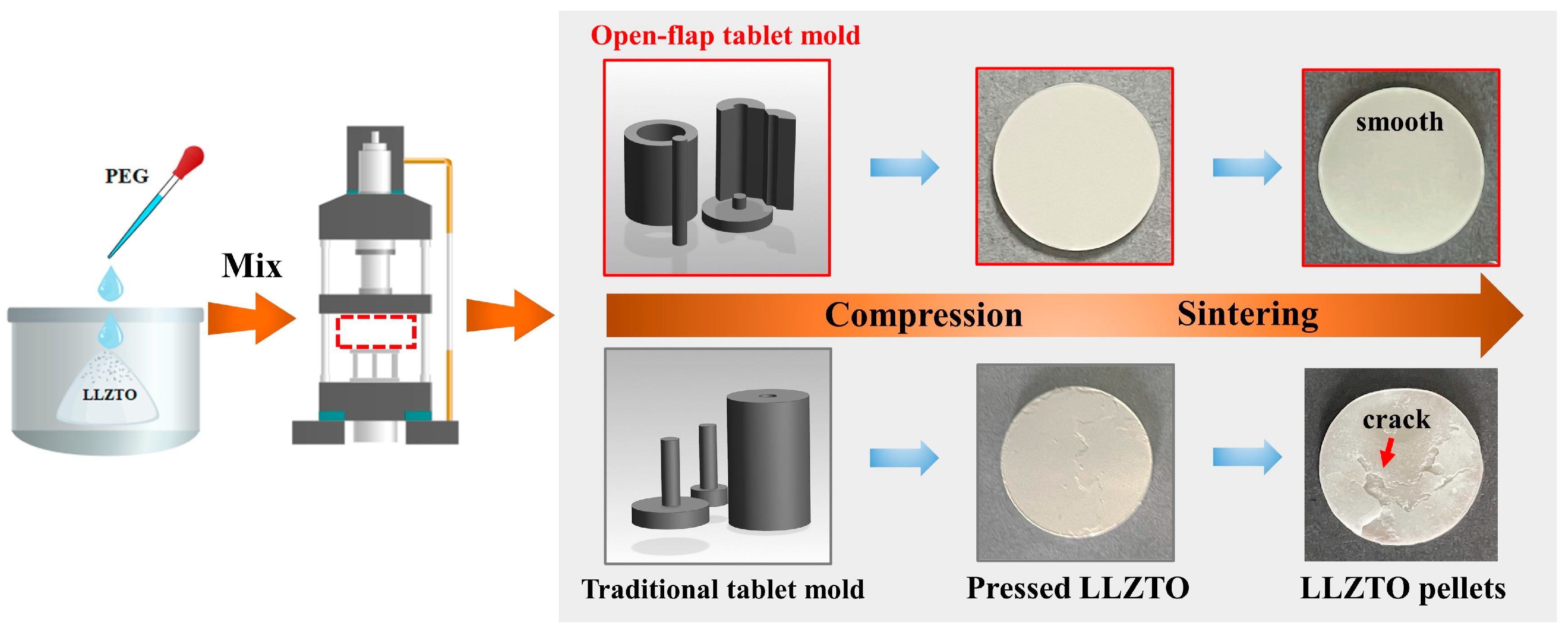
In the experimental setup, the materials used included high-purity LLZTO (with a purity of 99.99%) obtained from Kejing Zhida Co. Ltd (China). To act as a binder, polyethylene glycol (PEG) with a purity of 99% was added. The process began by weighing the PEG powders and subsequently dissolving them in deionized water at a ratio of 1:10. The dissolution process took place at a temperature of 40 °C. The cooled PEG solution was mixed with an appropriate amount of LLZTO powder. In order to prevent the block from being damaged during the demolding process, an open-flap tablet pressing mold was designed. After the PEG-containing mixture was prepared, it was pressed at a pressure of 20 MPa to form a compact block with a diameter of 12 mm. To obtain the LLZTO solid electrolyte bulks, a two-step sintering method was employed. The first step involved sintering the pressed block at a temperature of 800 °C for a duration of 120 min. Subsequently, the sintered block was further treated by sintering at a higher temperature of 1200 °C for a total duration of 600 min. This process resulted in the formation of the final LLZTO solid electrolyte bulks used for further experimentation and analysis. The entire sintering process was carried out within an alumina crucible, with the sintering atmosphere being selected as ambient air. The sintered LLZTO was ground by 460/1000/2000/3000 sandpaper in sequence to obtain a smooth surface. The sample without any additional coating is referred to as “bare LLZTO”.
2.2. ALD Surface Coating Combined with Annealing to Realize the Grain Boundary Design
The deposition of Al2O3 was carried out within a reaction chamber using ALD equipment integrated into a glovebox. This setup ensured that the oxygen and water content remained below 0.1 ppm, creating a meticulously controlled environment for the deposition process. Trimethyl aluminum (TMA) and deionized water were chosen as the sources for aluminum and oxygen, respectively. The ALD process involved using argon as a cleaning gas with a flow rate of 50 standard cubic centimeters per minute (SCCM) to purge any excess precursor gas and maintain a stable and precise deposition environment. This meticulous control of the deposition process ensures the desired characteristics and performance of the Al2O3 interlayer for solid-state batteries. Operating at a temperature of 150 °C, the ALD process effectively produces a uniform and conformal Al2O3 layer on the surface of the sample. In the ALD process, each cycle comprises seven steps. Firstly, water vapor is introduced for 0.5 s, followed by the introduction of argon gas for 15 s to remove residual water vapor. Next, TMA is introduced for 0.3 s, and then argon gas is introduced for 15 s to remove any remaining TMA. Finally, a mechanical pump is used for 15 s to clear all residual gases. The inclusion of a 0.3 s static period after introducing the water vapor and TMA allows for a more thorough and efficient reaction process. Here, about 10 nm of Al2O3 was deposited on the LLZTO. This sample is called “LLZTO@Al2O3”. The samples coated with Al2O3 were placed in a muffle furnace for annealing at 700 °C for about 2 h in an ambient air atmosphere to obtain the “LLZTO@Al2O3-annealed” sample.
2.3. Characterization of Materials
X-ray diffraction (XRD) using an Advance D8 instrument was utilized to analyze the phase structure of the material. The surface and cross-sectional morphology as well as the microstructure of the material were observed using a scanning electron microscope (SEM), specifically the TESCAN8000 model. To prepare specimens for transmission electron microscopy (TEM) and to analyze both the surface and cross-sectional morphology, a combination of a focused ion beam (FIB) and scanning electron microscopy (SEM), referred to as the FIB-SEM technique, was utilized. The specific FIB-SEM instrument used was the Helios Nanolab 600i manufactured by FEI. The transparent lamellae were obtained by Ga ion FIB milling (30 keV, 0.79 nA) and later fine polishing (2 keV, 9 pA). The microstructure characterization, energy-dispersive X-ray (EDX) analysis, and mapping were conducted using a Titan G2 TEM instrument, which operates at 300 kV and is manufactured by FEI.
2.4. Battery Sample Preparation and Electrochemical Testing
The investigation involved the use of Li||NCM811 full-cell and symmetric battery configurations. Three different SEs were utilized for the study, including bare LLZTO, LLZTO@Al2O3, and LLZTO@Al2O3-annealed. To prepare the LiNi0.8Mn0.1Co0.1O2 (NMC811) cathode, the following steps were followed. First, carbon black (CB) was mixed with NMC811 powders from Timcal, MTI Corporation, USA. The mixture was thoroughly ground to achieve a uniform distribution of components. Second, Poly (vinylidene fluoride) (PVDF) was added to the mixture in N-methyl-2-pyrrolidone (NMP). The mass fraction ratio employed was 8:1:1, corresponding to the NMC811, CB, and PVDF components, respectively. Third, the slurry obtained in the previous step was coated onto the surface of the solid electrolyte. Fourth, the coated solid electrolyte was subjected to drying in a vacuum drying oven at a temperature of 80 °C for a duration of 6 h under vacuum conditions. Fifth, the final cathode obtained after drying had an average active material loading mass of 1.8–2.0 mg cm−2. Sixth, type-2032 coin cells were assembled or disassembled within an ultrapure argon-filled glovebox. This controlled environment was maintained to prevent exposure to moisture and ensure a controlled experimental setup. Seventh, the assembly of the coin cells was accomplished using a manual hydraulic coin cell sealing machine (MSK-110, MTI Corporation, USA). This procedure was employed to achieve appropriate sealing and to prevent any potential exposure to moisture or impurities.
A CT-2001A electrochemical test system was employed to assess the cycle and rate capability of the lithium symmetrical battery. Additionally, a CHI660E electrochemical workstation was utilized to measure the internal resistance of the lithium symmetrical battery. The testing frequency range spanned from 0.01 Hz to 1 MHz, while the voltage amplitude was set to 10 mV.
The experimental setup and testing procedures for the solid-state batteries were as follows. The working voltage window of the solid-state batteries was set to be 2.7–4.3 V. Two formation cycles were conducted at a low rate of 0.1 C (1 C = 180 mA g−1) before initiating the cycling tests. After the formation cycles, the solid-state batteries were subjected to cycling tests at two different rates, namely 0.5 C and 1 C. The tests were carried out at a temperature of 25 °C. A liquid electrolyte with a composition of 1.0 M LiTFSI dissolved in a mixture of DME/DOL (1:1 Vol %) with 1.0% LiNO3 was used. The LLZTO surface of the solid-state electrolyte disc, which had a diameter of 12 mm and a thickness of 0.5 mm, was impregnated with a liquid electrolyte. A total of 5 μL per side of the liquid electrolyte was applied. The solid-state batteries were assembled using a curling pressure of 50 MPa to ensure proper contact and adhesion between the components. The cycle and rate capability of the lithium symmetrical battery were assessed through the utilization of an electrochemical test system (CT-2001A). Furthermore, the internal resistance of the lithium symmetrical battery was gauged via an electrochemical workstation (CHI660E), which operated within a test frequency range spanning from 0.01 Hz to 1 MHz. Additionally, a voltage amplitude of 10 mV was employed in these measurements.
3. Results and Discussion
The synthetic route of LLZTO is illustrated in
Figure 1. To fabricate LLZTO pellets, a mixture of LLZTO powder and PEG was compressed into circular plates using a specifically designed open-flap tablet pressing mold. The resulting plates had a diameter of 12 mm. Using traditional cold pressing molds can lead to an uneven stress distribution, causing edge cracking or fracturing during demolding. Cracks may be present on the green compacts formed by cold pressing, and these cracks do not heal during sintering, resulting in cracks in the final sintered products [
37,
38,
39]. These internal cracks in the solid-state electrolyte significantly affect ion transport and electron transport while also adversely impacting the mechanical strength of the solid-state electrolyte. To address these issues, we developed an open-flap tablet mold to avoid structural damage during demolding. The use of this self-developed open-flap tablet mold preserves the integrity of the circular compacts and, after sintering, the compacts exhibit a smooth surface with good surface morphology. This approach helps eliminate the appearance of cracks and ensures better mechanical strength in the solid-state electrolyte. The smooth surface morphology and absence of cracks after sintering are crucial factors in enhancing the overall functionality and stability of the final solid-state electrolyte pellets.
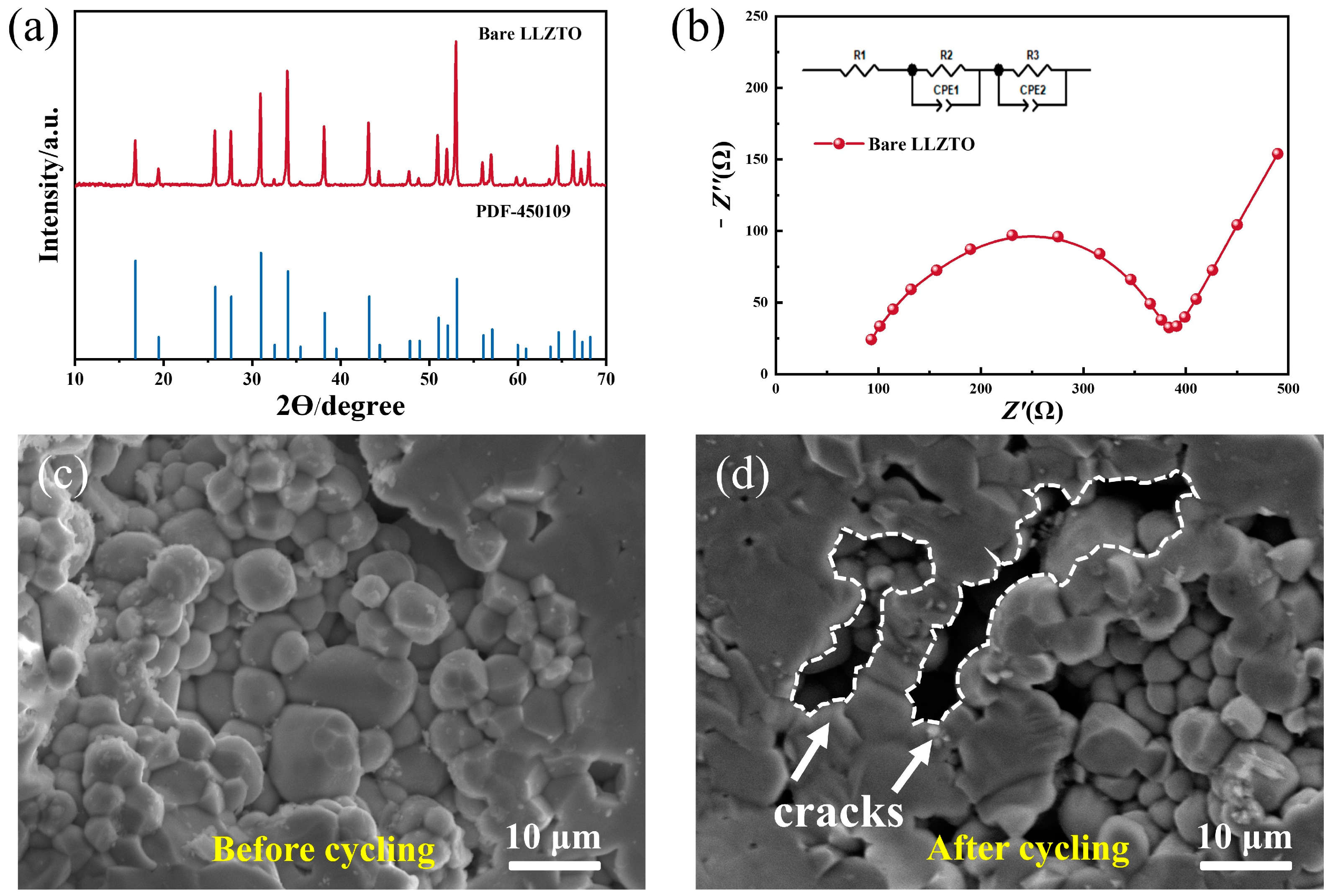
The X-ray diffraction (XRD) patterns of the LLZTO pellets are presented in
Figure 2a. It is evident that the major peaks align well with the standard pattern of cubic-LLZO (ICSD#45-0109). This observation confirms the successful preparation of the cubic phase LLZTO material. The presence of characteristic peaks indicates that the crystal structure of the LLZTO pellets is consistent with the expected cubic phase, validating the synthesis process. To further illustrate the exceptional electrochemical performance of the prepared LLZTO, Electrochemical Impedance Spectroscopy (EIS) characterization was carried out. In
Figure 2b, the inset showcases the equivalent circuit that was utilized to match the impedance spectra using Zview software. The impedance test was performed using a symmetrical battery structure, which has a simple design with stainless steel plates at both ends directly connected to LLZTO. At high frequencies, a capacitive arc related to the electrolyte grain boundary response was observed, while at low frequencies a linear response was seen due to lithium diffusion at the electrode. The real part impedance at the intersection of the capacitive arc and the linear response corresponds to the total impedance of LLZTO. Based on the impedance values [
40], the Li
+ ionic conductivity at room temperature (approximately 25 °C) was calculated to be about 4.6 × 10
−4 S cm
−1. The SEM image of the cleaved cross-section of a sintered LLZTO pellet is depicted in
Figure 2c. The outcomes presented above indicate the successful synthesis of high-quality LLZTO pellets. In solid oxide electrolytes, the infiltration of Li is closely linked to the local electronic band structure. Indeed, at the GBs of solid electrolytes like LLZTO, the electronic conductivity is typically higher compared with the bulk material. This increased electronic conductivity can lead to the accumulation of electrons at the GBs, creating localized regions with a high electron concentration. The presence of these accumulated electrons at the GBs can facilitate the premature reduction of Li
+ ions during the charge and discharge cycles in solid-state batteries, which can cause safety issues and lead to short circuiting or capacity loss in the battery. At the GBs, the electronic conductivity increases, causing many electrons to be enriched at the grain boundary, resulting in the premature reduction of Li
+ and the formation of Li filaments. After 50 cycles, the LLZTO from the disassembled battery was soaked in ethanol, which dissolved the lithium filaments produced by local deposition in LLZTO during cycling. Several cracks appeared in the LLZTO pellets after cycling, resulting in a significant reduction in contact between particles compared with the original sample (
Figure 2d). This phenomenon can be detected more clearly at a lower magnification, as shown in
Figure S2, and this crack is quite different from the mechanical crack caused during disassembly (
Figure S2c). It may be due to the accumulation and growth of “dead Li” at the GBs of the original LLZTO, leading to the formation of cracks.
Herein, we attempted to prevent the formation of Li filaments at GBs by modifying them through annealing after coating.
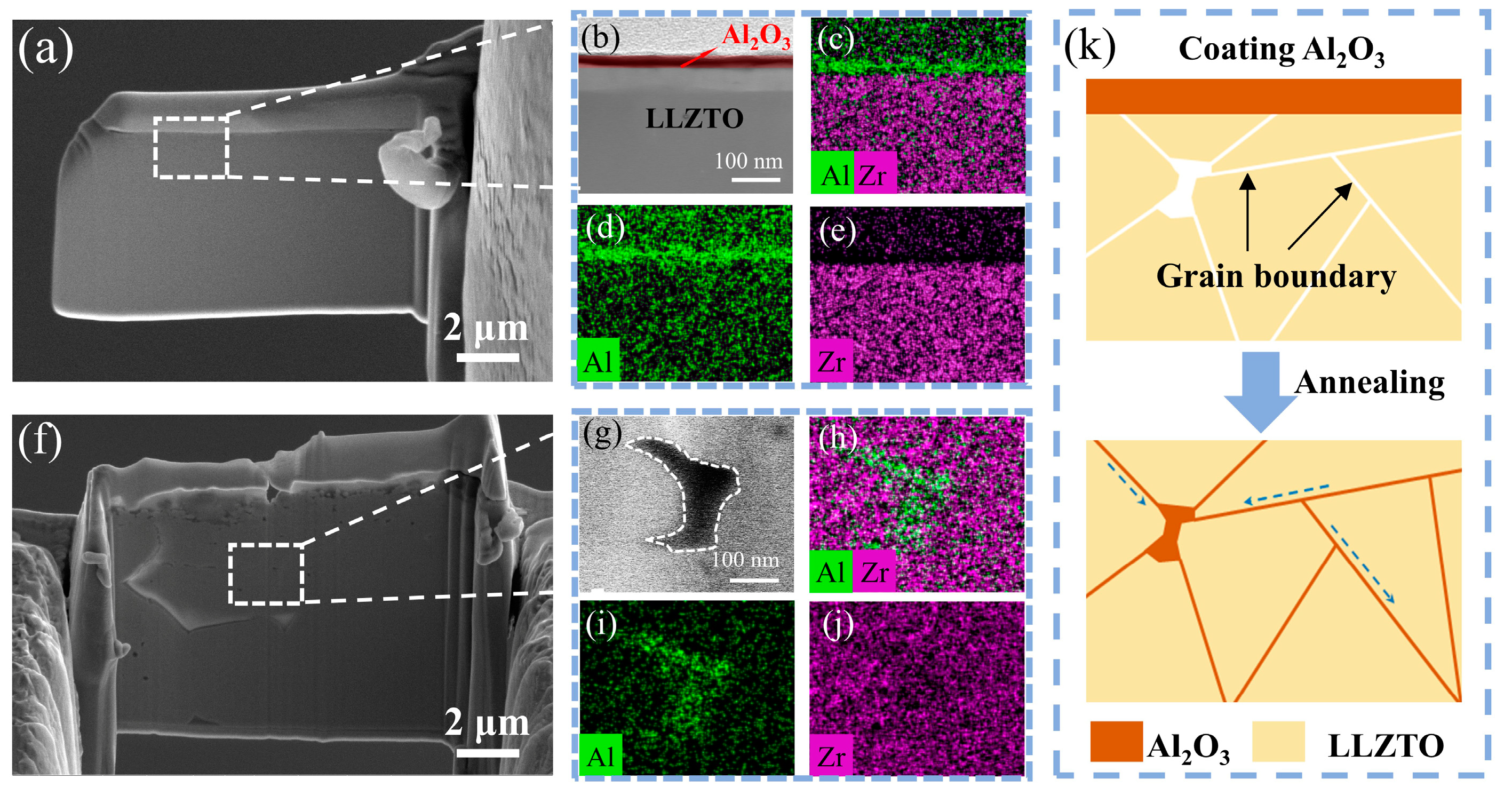
Figure 3a depicts the cross-sectional SEM morphology of LLZTO coated with Al
2O
3 through ALD, while
Figure 3b provides a TEM image of the enclosed region within
Figure 3a. The imagery reveals that the LLZTO surface is consistently enveloped by a coating layer of approximately 10 nm thickness.
Figure 3c–e shows the EDS mapping of an LLZTO garnet pellet that has been coated with Al
2O
3. In the EDS mapping, it was observed that Zr and Al elements are present in the LLZTO garnet, with the presence of Al being attributed to the deposited Al
2O
3. The distribution of Al demonstrates that the Al
2O
3 coating is exclusively present on the surface of LLZTO, while there is no presence of Al within its interior. Furthermore, we studied the microstructure change of the GBs during the annealing process.
Figure 3f shows the cross-sectional SEM image of the LLZTO@Al
2O
3-annealed sample, and
Figure 3g presents a magnified image of the boxed area in
Figure 3f, where the position with a deeper contrast is the GBs in the LLZTO. Impressively, after annealing, it was found that Al infiltrated into the GBs as shown in
Figure 3h,i. In LLZTO, most of the grain boundaries (GBs) are typically narrow and may slightly widen near triple junctions where three grains meet. These GBs exhibit structural asymmetry and are primarily composed of grains that are randomly oriented. Hence, the presence of Al
2O
3 entering the interior of LLZTO is more prominently characterized at the triple junction’s location. A schematic diagram of the Al
2O
3 infusion is shown in
Figure 3k. The high temperature cannot lead to the LLZTO grains’ decomposition and promotes surface Al
2O
3 diffusion. Therefore, Al is enriched at the GBs and does not enter the interior of the grains, forming a uniform GB modification layer.
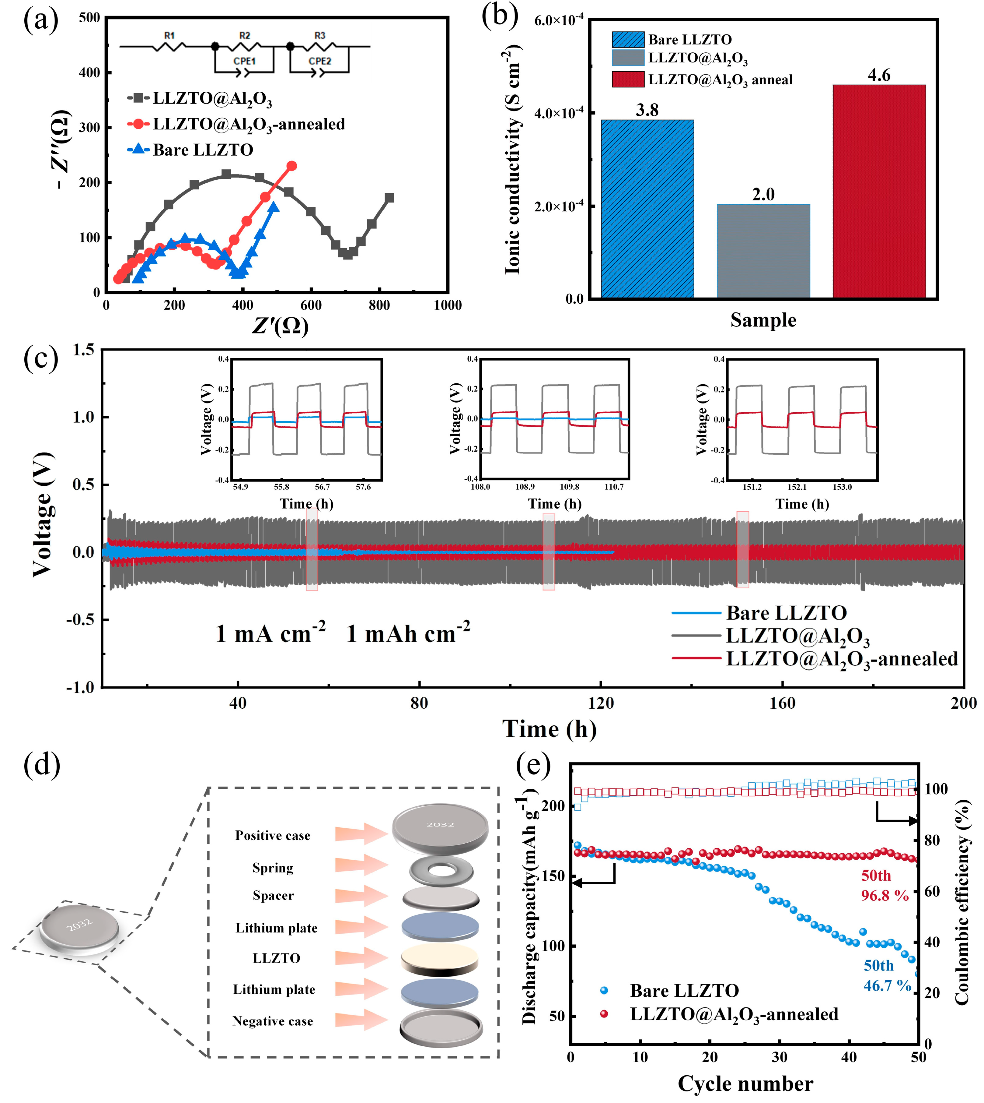
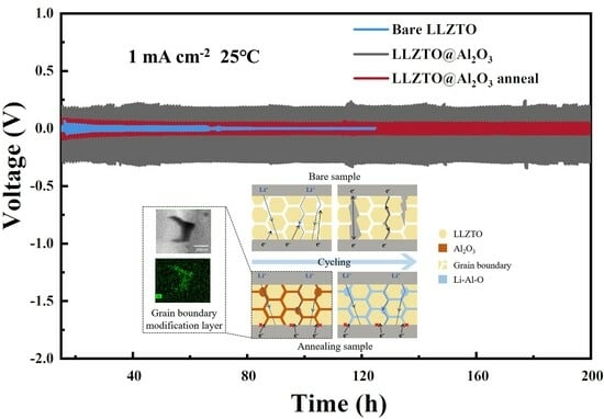
Electrochemical testing was conducted to validate the role of GB engineering in the study. Impedance diagrams of the coating and annealing samples (
Figure 4a) showed that the internal resistance of the annealing sample was attenuated compared with the unmodified sample. The addition of aluminum oxides to the grain boundaries and surface coating of solid-state batteries improves their stability against electronic transmission; thus, the samples with Al
2O
3 exhibited higher impedance. The annealed sample exhibited an ionic conductivity of 4.6 × 10
−4 s cm
−2 (as shown in
Figure 4b). Despite detecting a relatively higher internal resistance in the LLZTO sample coated with Al
2O
3, the ion conductivity of the LLZTO sample demonstrated an improvement after undergoing the annealing treatment with the Al
2O
3 coating layer. The symmetric cells are commonly used to test the cycling performance of electrolytes [
41]. The structural diagram is shown in
Figure 4d. The Li/LLZTO@Al
2O
3-annealed/Li symmetric cell was able to cycle stably for 200 h at 1 mA cm
−2, while the Li/LLZTO/Li symmetric cell cycled for only 60 h at 1 mA cm
−2 (
Figure 4c).
Figure S5 illustrates a magnified view of the region highlighted in
Figure 4c. The solid electrolyte was then paired with an NMC811 cathode to study the effectiveness of LLZTO@Al
2O
3-annealed on the full-cell cycling performance. The electrochemical performance of Li/Bare LLZTO/NMC811 and Li/LLZTO@Al
2O
3-annealed/NMC811 cells is presented in
Figure 4e. The Li/Bare LLZTO/NMC811 and Li/LLZTO@Al
2O
3-annealed/NMC811 batteries initially exhibited a similar specific capacity, around 160 mAh g
−1, during the early cycles. After 50 cycles, the Li/Bare LLZTO/NMC811 battery experienced continuous capacity decay, with only 80.3 mAh g
−1 of capacity remaining. On the contrary, the Li/LLZTO@Al
2O
3-annealed/NMC811 battery exhibited a significantly higher discharge capacity, retaining 161.6 mAh g
−1 after undergoing 50 cycles. The capacity retention rates were calculated to be 46.7% for the bare sample and a notable 96.8% for the annealed sample battery. These results further confirmed that, compared with unmodified samples, LLZTO with a grain boundary modification layer exhibits higher ion conductivity and excellent cycling performance.
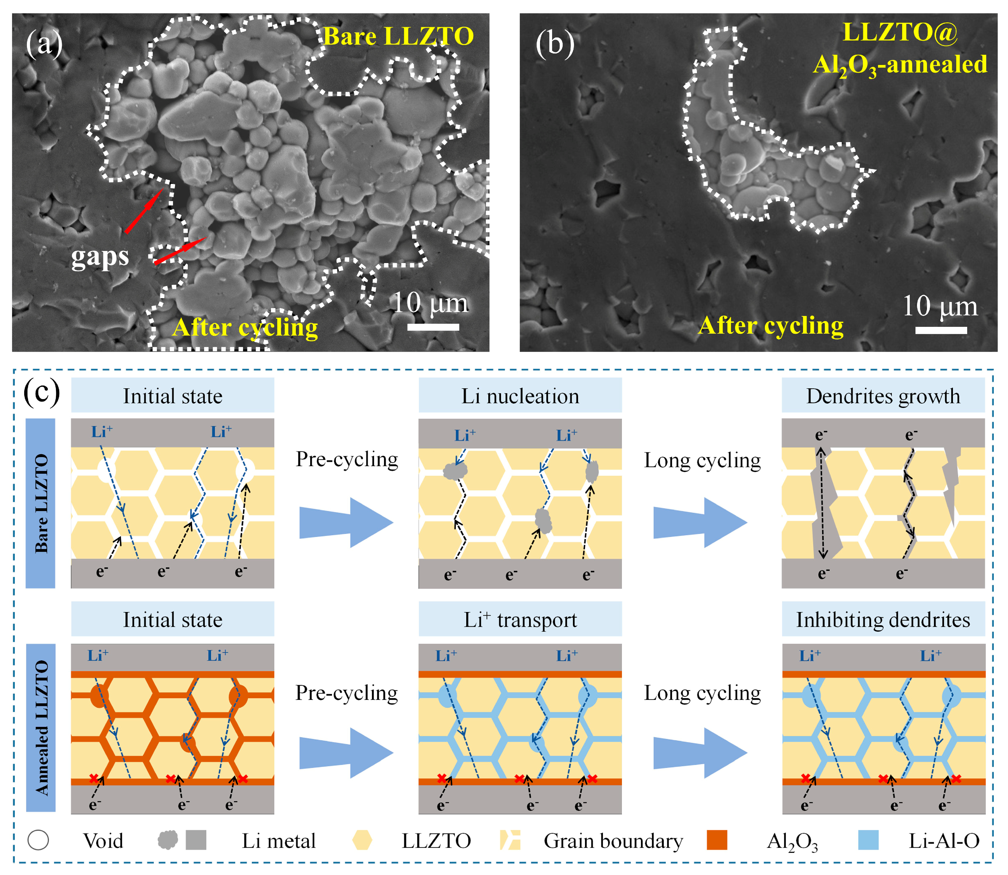
The LLZTO with a uniform GB modification layer exhibited excellent cycling performance, and our research endeavored to unravel the underlying mechanisms behind the functioning of the modifying layer in this context. As shown in
Figure 5a, after 50 cycles, the bare sample exhibited numerous gaps in the SEM image and less contact between particles, which may have resulted from localized lithium deposition during cycling. During the cycling process’s progression, Li filaments grew, causing the battery to short circuit. However, the annealed sample did not show obvious gaps or cracks after 50 cycles (
Figure 5b). Observed in a larger field of view, the annealed sample showed fewer traces of lithium deposition compared with the pristine sample (
Figure S3). Building upon the foundation of the experimental analysis, we formulated the following hypotheses. In the initial unmodified sample depicted in
Figure 5c, intrinsic defects and pores inherent to LLZTO serve as initiation sites for the nucleation of lithium dendrites, which subsequently undergo progressive growth. This process results in the generation of a substantial number of residual cracks. In samples modified by grain boundaries, the initial nucleation of lithium dendrites was suppressed, resulting in the absence of a significant number of cracks observed during 50 cycles. During battery cycling, Al
2O
3 at the GBs gradually becomes a Li-Al-O mixture, ensuring efficient ion conduction at the GBs. The uniform and dense coating of Al
2O
3 by ALD ensures a consistent and stable interface, reducing the likelihood of localized flaws. This indicates that the modification layer at the grain boundary improves the ion conduction, reduces the initial deposition in the intrinsic void pores, makes the ion transport channel more uniform, and reduces the growth of dendrites. Overall, the use of ALD to coat an ultrathin layer of Al
2O
3 and anneal it is a promising method for modifying the grain boundaries of LLZTO.


