Article

Micro-Sized MoS6@15%Li7P3S11 Composite Enables Stable All-Solid-State Battery with High Capacity

1
Ningbo Institute of Materials Technology and Engineering, Chinese Academy of Sciences, Ningbo 315201, China
2
Municipal Key Laboratory of Clean Energy Technologies of Ningbo, University of Nottingham Ningbo China, Ningbo 315100, China
3
Department of Chemical and Environmental Engineering, University of Nottingham Ningbo China, Ningbo 315100, China
4
Center of Materials Science and Optoelectronics Engineering, University of Chinese Academy of Sciences, Beijing 100049, China
5
Key Laboratory of Carbonaceous Wastes Processing and Process Intensification of Zhejiang, Ningbo 315100, China
*
Authors to whom correspondence should be addressed.
Batteries 2023, 9(11), 560; https://doi.org/10.3390/batteries9110560
Submission received: 19 October 2023 / Revised: 11 November 2023 / Accepted: 15 November 2023 / Published: 17 November 2023

Abstract

:
All-solid-state lithium batteries without any liquid organic electrolytes can realize high energy density while eliminating flammability issues. Active materials with high specific capacity and favorable interfacial contact within the cathode layer are crucial to the realization of good electrochemical performance. Herein, we report a high-capacity polysulfide cathode material, MoS6@15%Li7P3S11, with a particle size of 1–4 μm. The MoS6 exhibited an impressive initial specific capacity of 913.9 mAh g−1 at 0.1 A g−1. When coupled with the Li7P3S11 electrolyte coating layer, the resultant MoS6@15%Li7P3S11 composite showed improved interfacial contact and an optimized ionic diffusivity range from 10−12–10−11 cm2 s−1 to 10−11–10−10 cm2 s−1. The Li/Li6PS5Cl/MoS6@15%Li7P3S11 all-solid-state lithium battery delivered ultra-high initial and reversible specific capacities of 1083.8 mAh g−1 and 851.5 mAh g−1, respectively, at a current density of 0.1 A g−1 within 1.0–3.0 V. Even under 1 A g−1, the battery maintained a reversible specific capacity of 400 mAh g−1 after 1000 cycles. This work outlines a promising cathode material with intimate interfacial contact and superior ionic transport kinetics within the cathode layer as well as high specific capacity for use in all-solid-state lithium batteries.

1. Introduction

Commercial lithium-ion batteries have been utilized broadly in the fields of plug-in hybrid/electric vehicles, smartphones, laptop computers, and other portable electronic devices for the past several decades. They significantly reduce environmental pollution and greenhouse gas emissions. The energy densities of lithium-ion batteries are close to their limitation because of the low theoretical capacities of oxide cathodes (i.e., LiFePO4, LiCoO2, LiMn2O4, and LiNixMnyCozO2) and graphite anode materials [1]. Lithium–sulfur batteries that use lithium metal anodes instead of graphite can theoretically reach high specific capacity values [2]. However, there are safety concerns, such as leakage and risk of explosion, associated with organic liquid electrolyte-based lithium–sulfur batteries, and they exhibit poor rate capability and cycling stability due to the huge changes in the volume of sulfur that occur during the charge/discharge process. All-solid-state lithium batteries with nonflammable inorganic solid-state electrolytes have attracted considerable attention in the field of energy storage [3,4,5]. Among the various solid electrolytes, sulfide solid electrolytes have broad application potential because of their high ionic conductivity and low elastic modulus. For example, the Li10GeP2S12 sulfide solid electrolyte [6] possesses a high ionic conductivity of around 10−2 S cm−1 and surpasses the liquid electrolytes used in traditional lithium-ion batteries. The electrochemical stability of the Li6PS5Cl electrolyte was also investigated, and it displayed excellent stability when in contact with lithium metal [7].
Not only is the selection of the sulfide solid electrolyte essential, but the selection of an appropriate cathode material is also key to achieving high performance all-solid-state batteries. The classical oxide cathode materials and transition metal sulfides display different reaction mechanisms during the charge/discharge process. For classical lithium intercalation process in oxide cathode materials, because the 3d metal cationic band is much higher than the p band of oxygen, the ion–electron transfer reactions occur from lithium to the lowest unoccupied energy level of the transition metal d band in ionic oxides. The discharge/charge (lithium ion intercalation/de-intercalation) process relies on the d metal level to host/release the associated electrons; this is called the cation-driven redox process. For transition metal sulfide materials, the p band of sulfur is located in a higher position and is therefore closer or even penetrate the d band of transition metal. Due to the charge transfer of these two bands, the anionic redox process is triggered, and this can improve the reversible capacity of the battery [8]. The use of transition metal sulfides such as a-TiS4 [9], FeS2 [10], NiS2 [11,12], and TiS3 [12] in all-solid-state batteries has been widely studied due to the low cost of raw materials and their abundant yields. Meanwhile, their relatively high transport kinetics can promote conductivity and reduce charge transfer resistance. Furthermore, sulfide electrolytes show superior compatibility with transition metal sulfide cathodes due to their similar chemical potential, thus realizing high energy density [13,14]. However, all-solid-state lithium batteries with sulfide electrolytes and transition metal sulfide cathodes still suffer from inferior interfacial contact within the cathode layer.
Traditional sulfide cathode materials based on insertion reactions can accommodate lithium ions in their lattices without serious structural changes occuring during the intercalation/de-intercalation reaction of x L i + + M S y + x e L i X M S y , in which M represents the transition metal [15]. Although insertion reaction-based cathode materials exhibit stability and long life cycles when used in all-solid-state lithium batteries, they still have intrinsic problems related to their limited space for lithium ions result in to a low specific capacity [8,16]. Nevertheless, in transition metal sulfide cathode materials with anionic redox driven chemistry (a-TiS4 [9], MoS3 [17], and FeS2 [10]), sulfur fully or partially exists in the state of S 2 2 pairs, and this has a strong influence on specific capacity. For example, MoS2 only has S 2 pairs and has a theoretical specific capacity of 670 mAh g−1 [18,19]. MoS3 has both S 2 2 and S 2 pairs and has a higher theoretical specific capacity of 837 mAh g−1 [17]. The electronic structure of the S 2 2 group allows them to donate or receive electrons. Their ability as donors is attributed to the π*g orbital, which can release electrons that convert S 2 2 to S 2 . Because of the reversible reaction of S 2 2 + 2 e = 2 S 2 , multi-electron reactions proceed during the charge/discharge process, resulting in a high specific capacity [8,19]. In addition, transition metal sulfides with anionic redox driven chemistry display a high voltage plateau of about 2 V, which is close to that of a lithium–sulfur battery.
Even though MoS2 and MoS3 demonstrate high theoretical specific capacities, the actual reversible specific capacities of MoS2 and MoS3 in all-solid-state lithium batteries are only 592 mAh g−1 (0.1 C, 0.1–3.0 V) and 747 mAh g−1 (0.05 A g−1, 0.5–3.0 V), respectively [19,20]. Ionic transport kinetics and interfacial contact within the cathode layer become crucial challenges. Coating a thin electrolyte layer onto the surfaces of active materials is an effectively strategy to enhance ionic transport kinetics and the contact between the solid electrolyte and the active material [17,21]. Compared with MoS2 and MoS3, MoS6 is considered one of the most promising cathode materials for all-solid-state lithium batteries because of its ultra-high theoretical specific capacity of 1117 mAh g−1, which is a result of its high S 2 2 content as well as its amorphous nature, according to which possess open and random transmission paths to achieve cycling stability [22]. It therefore has potential applications in high energy all-solid-state batteries.
In this work, a micro-sized cathode material composite, MoS6@15%Li7P3S11, is designed for use in all-solid-state lithium batteries. First, MoS6 was synthesized using a wet chemical method. After the in situ coating of the Li7P3S11 solid electrolyte onto the MoS6, the ionic diffusivity enhanced from 10−12–10−11 cm2 s−1 to 10−11–10−10 cm2 s−1. The Li/Li6PS5Cl/MoS6@15%Li7P3S11 all-solid-state lithium batteries exhibited high initial and reversible discharge capacities of 1083.8 mAh g−1 and 851.5 mAh g−1, respectively, at 0.1 A g−1 and 25 °C within 1.0–3.0 V. Because of the remarkable intimate interfacial contact between the active material MoS6 and the solid electrolyte, these all-solid-state batteries can realize a long cycle life of 1000 cycles with a high reversible specific capacity of 400 mAh g−1 at 1 A g−1 and 25 °C.

2. Materials and Methods

2.1. Synthesis of (NH4)2Mo2S12

(NH4)2Mo2S12, which was used as a precursor, was synthesized using wet chemical methods. Briefly, 4.5 g of (NH4)6Mo7O24·4H2O and 3 g of NH2OH·HCl were dissolved in 60 mL of water (50 °C). Next, 12 g of sulfur powder and 60 mL of (NH4)2S (6−20% aqueous solution) were mixed and stirred for 1 h. The two abovementioned solutions were mixed together and placed in an oven at 50 °C and 90 °C for 1 h and 4 h, respectively. After filtering, the filtrate was mixed with 20 mL of (NH4)2S and allowed to stand for 36 h. It was then filtered and washed with iced water, ethanol carbon disulfide, and iced diethyl ether. The obtained (NH4)2Mo2S12 displayed a crystal structure which matched the standard peaks in the PDF card (JCPDS: F73-0900) (Figure S1) [23].

2.2. Synthesis of Micro-Sized MoS6

The micro-sized MoS6 was prepared via an aqueous solution reaction corresponding to the reaction of ( N H 4 ) 2 M o 2 S 12 + I 2 = 2 N H 4 I + 2 M o S 6 . Accordingly, 0.28 g of (NH4)2Mo2S12 and 0.2 g of iodine were separately dissolved in N,N-dimethylformamide. Afterward, the two solutions were thoroughly mixed together and stirred continuously for 30 min. The obtained MoS6 was filtered, washed with N,N-dimethylformamide, CS2, and acetone, and finally dried and stored in an argon atmosphere.

2.3. Synthesis of MoS6@15%Li7P3S11 Composite

A in situ liquid phase reaction and an annealing process were conducted in order to prepare the MoS6@15%Li7P3S11 composite [17]. The prepared MoS6 was mixed with P2S5 and Li2S powders and then underwent magnetic stirring in anhydrous acetonitrile at 60 °C for 12 h. After removing the residual solvent, the Li7P3S11 precursor was in situ coated with MoS6, and the precursor was then collected and heated at 260 °C for about 1 h to obtain the MoS6@15%Li7P3S11 composite.
Details concerning the synthesis of Li10GeP2S12, Li6PS5Cl, and 75%Li2S-24%P2S5-1%P2O5 can be found elsewhere. The ionic conductivities of these solid electrolytes were 8.27 × 10⁻³ S cm−1 (Li10GeP2S12), 6.11 × 10⁻³ S cm−1 (Li6PS5Cl), and 1.54 × 10⁻³ S cm−1 (75%Li2S-24%P2S5-1%P2O5).

2.4. Material Characterization

X-ray diffraction (XRD) measurements were conducted using a Bruker D8 Advance Davinci (Karlsruhe, Germany) with Cu Kα radiation of λ = 1.54178 Å in a 2θ range of 10–60° to determine the crystal structure of the samples. Raman spectra results were recorded in a range of 250 to 580 cm−1 using a Raman spectrophotometer (Renishaw inVia Reflex, Gloucestershire, UK) with a 532 nm laser. The atom ratio of the MoS6 was analyzed via an inductively coupled plasma emission spectrometer analysis (ICP-OES, Spectro Arcos, Spectro, Dusseldorf, Germany). Field emission scanning electron microscopy (SEM, S-4800, Hitachi, Tokyo, Japan) and field emission scanning electron microscopy energy dispersive spectroscopy (SEM-EDS, S-4800, Hitachi, Tokyo, Japan) were conducted using an accelerated voltage of 15 kV to confirm the morphology, particle size, and elemental distribution. High-resolution transmission electron microscopy (HRTEM) was performed using an FEI Tecnai F20 (Hillsboro, OR, USA) with an accelerated voltage of 200 kV to confirm the existence of the Li7P3S11 solid sulfide electrolyte thin layer on the surface of the MoS6. An electrochemical workstation (Solartron 1470E, Bognor Regis, UK) was employed to conduct cyclic voltammetry (CV) measurements and electrochemical impedance spectroscopy (EIS). All of the samples used for the various measurements were prepared in glove boxes, and all of the measurements were obtained at room temperature.

2.5. Assemby and Evaluation of All-Solid-State Lithium Batteries

To analyze the electrochemical performances of the synthesized samples described above, the obtained MoS6, MoS6@15%Li7P3S11 composite, Li10GeP2S12, and Super P were homogeneously mixed with a weight ratio of 40:50:10. For the preparation of the Li/Li6PS5Cl/MoS6 all-solid-state batteries, Li6PS5Cl (150 mg) solid electrolyte pellets (ϕ = 10 mm) were fabricated via cold pressing at 240 MPa. The previously synthesized composite cathodes (~1 mg/cm2) were then homogeneously spread onto the electrolyte surface and cold pressing was applied again at 240 MPa. Finally, metallic lithium foil with a 10 mm diameter was attached to the other side of the Li6PS5Cl layer at 360 MPa. For the purpose of comparison, Li/75%Li2S-24%P2S5-1%P2O5/Li10GeP2S12/MoS6 all-solid-state batteries were fabricated as well. Bilayer pellets (ϕ = 10 mm) consisting of Li10GeP2S12 and orthorhombic phase 75%Li2S-24%P2S5-1%P2O5 were constructed at 240 MPa as well. The abovementioned cathodes were spread onto the sides of the Li10GeP2S12 solid electrolytes homogeneously, and this was followed by cold pressing at 240 MPa. Pieces of metallic lithium foil (ϕ = 10 mm) were placed onto the sides of the 75%Li2S-24%P2S5-1%P2O5 solid electrolytes by pressing them together at 360 MPa. The bilayer solid electrolyte pellets were necessary due to the instability caused by the side-reaction of the Li10GeP2S12 and the lithium metal. All of these processes were carried out in a glove box with a dry argon atmosphere.
Galvanostatic charge and discharge tests were conducted at room temperature on a multi-channel battery test system under various current densities with voltages ranging from 1.0 V to 3.0 V. The galvanostatic intermittent titration technique (GITT) was used at 1 A g−1 for 1 min followed by a 120 min rest. The Li ion diffusion coefficient ( D ) was determined using Equation (1), which is based on the Fick’s second law [24]:
D = 4 π τ n m v m S 2 E s E t 2  
where τ is the duration of the pulse, n m and v m are the molar mass (mol) and volume (cm3/mol) of the active material, respectively, S is the cell interfacial area, and E s and E t are the voltage drops of the pulse and discharge processes [25].

3. Results and Discussions

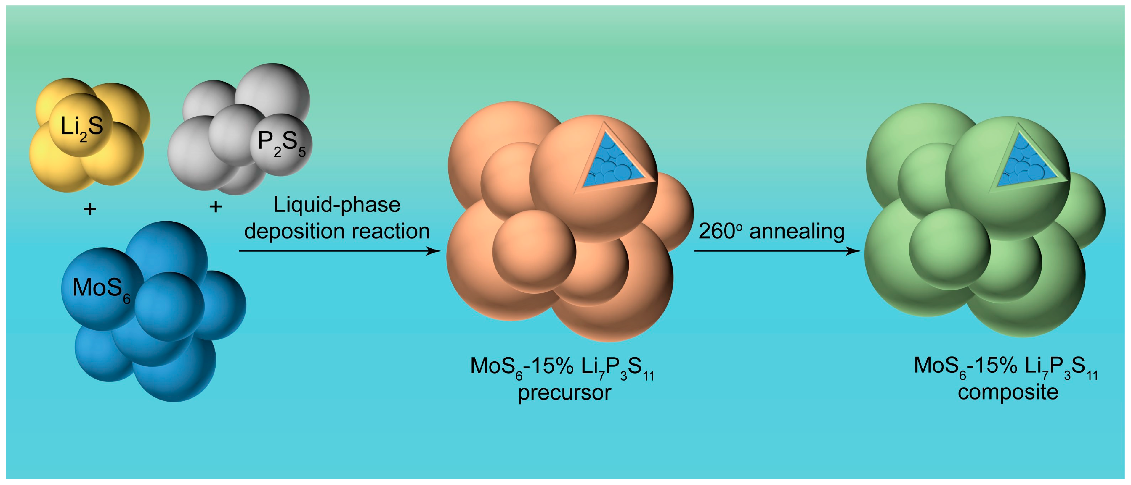
To better demonstrate the properties of the prepared sample, the Mo/S atom ratio was measured using an inductively coupled plasma emission spectrometer (ICP) (Table S1). The actual remaining weight ratios of the Mo and S were 31.5 wt% and 63.5 wt%, respectively, indicating an Mo/S ratio of 6.036, which is in agreement with the theoretical value of 6. The procedure for synthesizing the MoS6@15%Li7P3S11 composite is schematically illustrated in Figure 1. A Li7P3S11 solid electrolyte precursor was in situ coated onto the MoS6 surface during facile liquid phase deposition. After a 260 °C annealing treatment, the MoS6@15%Li7P3S11 composite was successfully prepared.
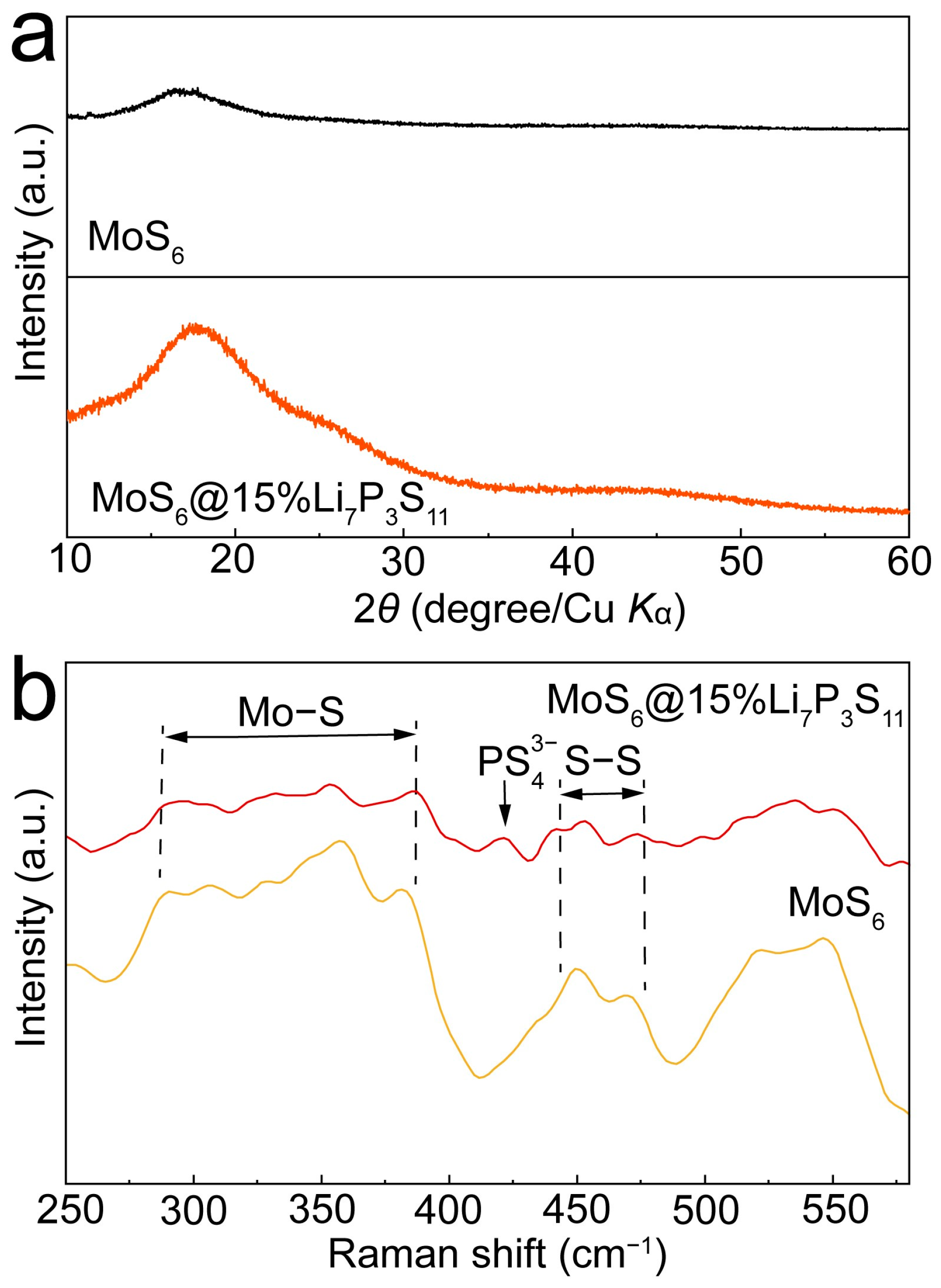
The XRD patterns of the MoS6 and MoS6@15%Li7P3S11 composite are shown in Figure 2a, and they confirm the amorphous nature of MoS6. No characteristic peaks were detected for the Li7P3S11 sulfide electrolytes, indicating the low amount of Li7P3S11 sulfide electrolytes in the coating layer. In order to confirm the existence of the Li7P3S11 sulfide solid electrolytes in the MoS6@15%Li7P3S11 composite, Raman spectroscopy was performed (Figure 2b). The peaks located in the ranges of 286–385 cm−1 and 518–550 cm−1 correspond to vibrations of molybdenum sulfide bonds and bridging disulfide/terminal disulfide [26,27]. Furthermore, the peak located at 421cm−1 can be attributed to the P S 4 3 in the Li7P3S11 sulfide solid electrolyte [21].
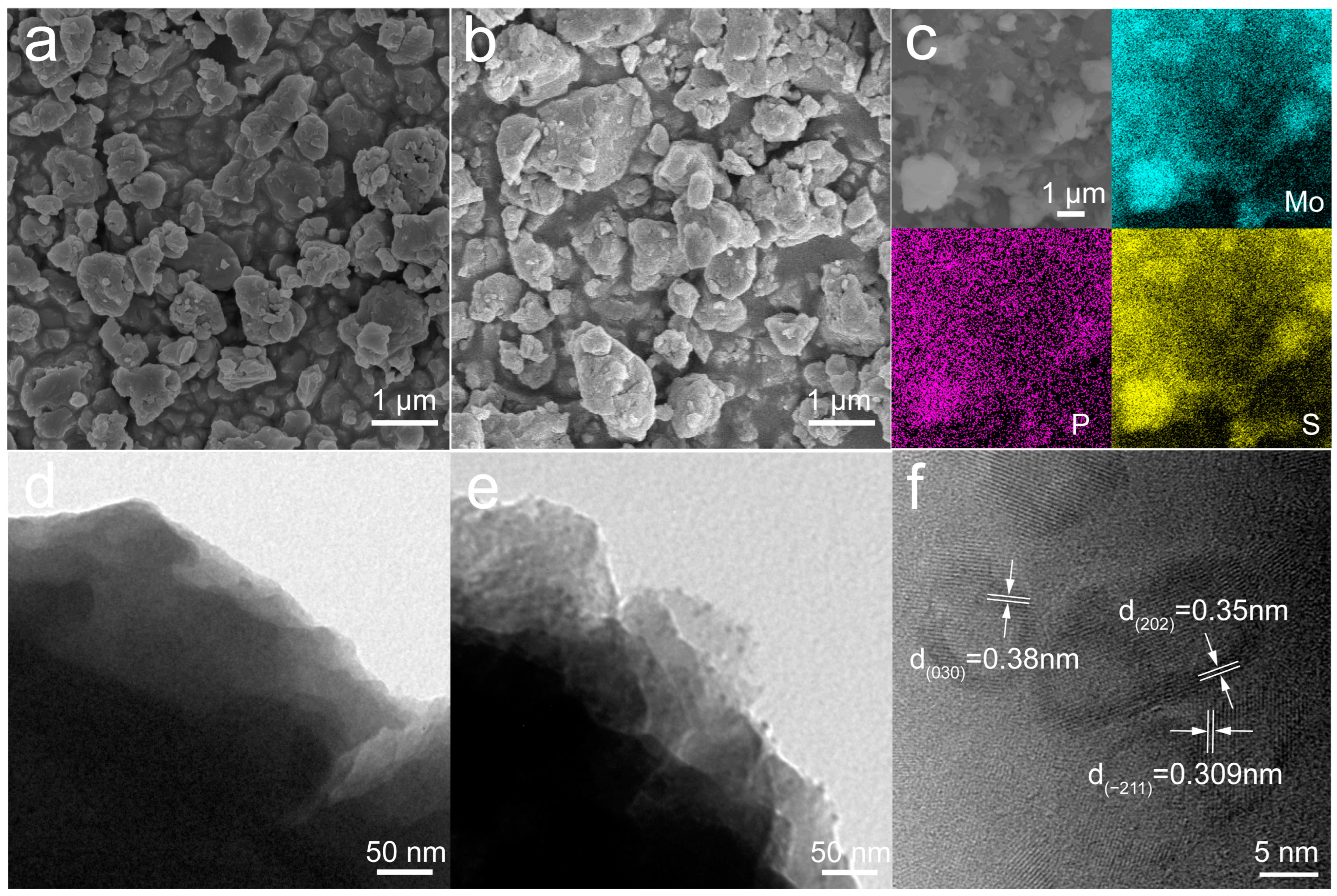
The morphology and microstructure of the MoS6 and MoS6@15%Li7P3S11 composite were observed using SEM and HRTEM (Figure 3). The particle sizes of the MoS6 and MoS6@15%Li7P3S11 composite were in the range of 1–4 μm (Figure 3a,b). EDS mapping of the MoS6@15%Li7P3S11 composite clearly illustrates the good distribution of molybdenum (blue), phosphorus (purple), and sulfur (yellow) (Figure 3c). The HRTEM images further confirmed that Li7P3S11 solid electrolytes were uniformly growing on the surface of the MoS6 (Figure 3d,e), and this facilitates improvements in ionic transport kinetics and the formation of intimate interfacial contact. The d-spacings of 0.38, 0.35, and 0.309 nm correspond to the d030, d202, and d−211 spacing of the Li7P3S11, respectively (Figure 3f) [21].
The electrochemical performance of the MoS6 was tested in all-solid-state lithium batteries. Two types of battery configuration were employed at 25 °C and 0.2 A g−1, i.e., Li/Li6PS5Cl/MoS6 and Li/75%Li2S-24%P2S5-1%P2O5/Li10GeP2S12/MoS6 all-solid-state batteries. As Figure S2 shows, the Li/Li6PS5Cl/MoS6 all-solid-state battery exhibited a reversible specific capacity of 361.8 mAh g−1 after 200 cycles, which was higher than the value exhibited by the Li/Li10GeP2S12/75%Li2S-24%P2S5-1%P2O5/MoS6 all-solid-state battery (78.3 mAh g−1), indicating a better capacity retention. For the purpose of comparison, cycles of 50MoS6:50Li10GeP2S12, 40MoS6:50Li10GeP2S12:10Super P, and 40MoS6:40Li10GeP2S12:20Super P were performed at 0.1 A g−1 and 25 °C to determine the appropriate mixing ratio, as is shown in Figure S3. The capacity retention of the 40MoS6:50Li10GeP2S12:10Super P was 544.8 mAh g−1 after 10 cycles; this was higher than the 394.69 mAh g−1 and 438.29 mAh g−1 values observed for the 50MoS6:50Li10GeP2S12 and 40MoS6:40Li10GeP2S12:20Super P, respectively, and indicated a high reversible discharge capacity.
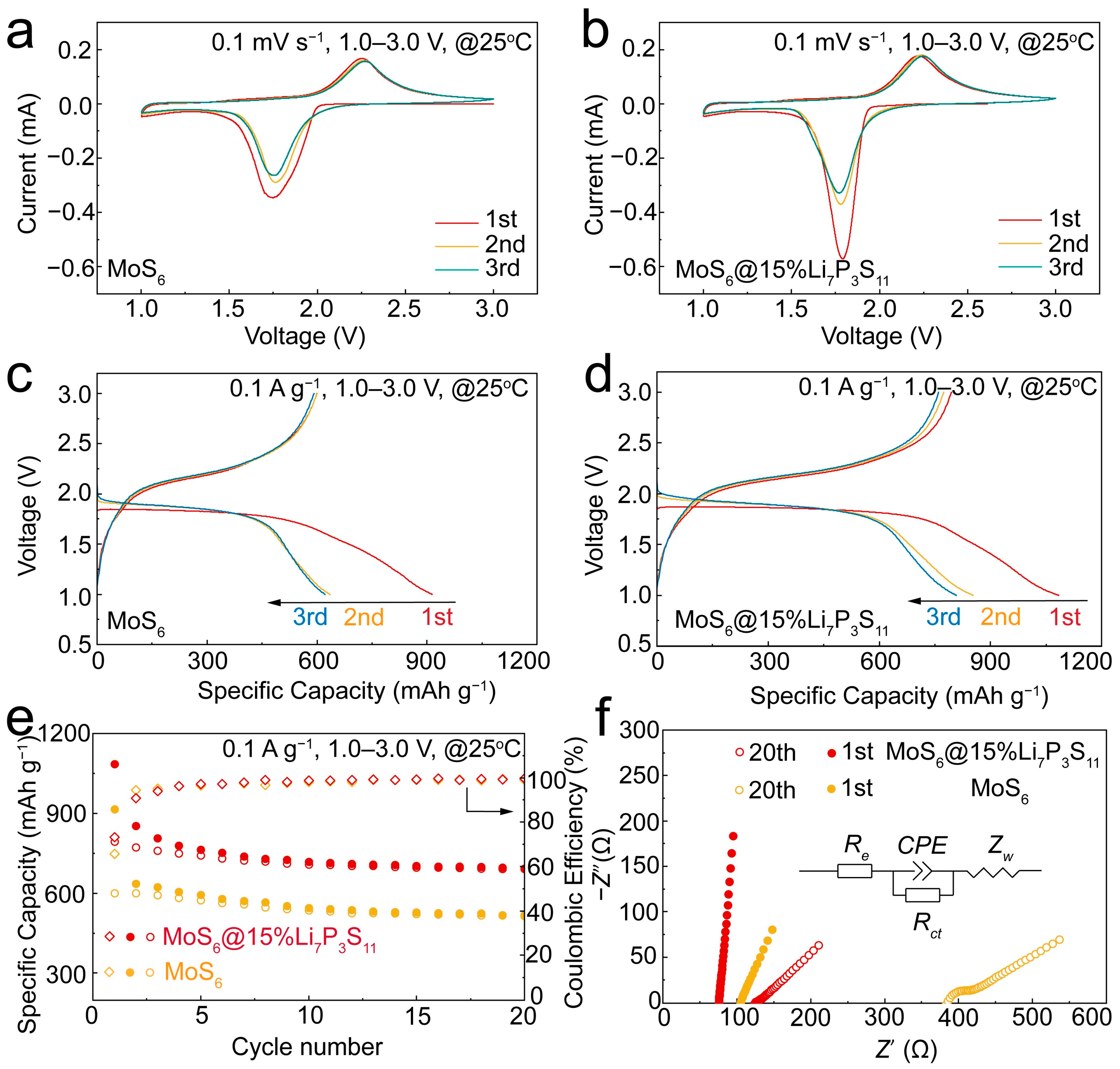
To reveal the electrochemical reaction mechanisms of the MoS6 and MoS6@15% Li7P3S11 composite, CV curves were generated for the Li/Li6PS5Cl/MoS6 and Li/Li6PS5Cl/MoS6@15%Li7P3S11 all-solid-state batteries for the first three cycles, and these are shown in Figure 4a,b. During the first cathodic scan, there was a reduction peak at around 1.75 V which can be attributed to the lithiation process of the MoS6 and a further conversion process. During the initial anodic scanning period, the oxidation peak which occurred at 2.25 V corresponds to the de-lithiation processes and the forming of molybdenum sulfides. The CV curves of the MoS6@15%Li7P3S11 composite are similar to those of the MoS6; they show the same electrochemical reaction process [21,28]. Even so, the redox peaks of the MoS6@15%Li7P3S11 composite are narrower and stronger than those of the MoS6, illustrating enhancements in the reversibility and electrochemical reaction kinetics resulting from favorable ionic diffusion. In the second cycle, the CV curves display an apparent tendency to overlap, which indicates that the MoS6@15%Li7P3S11 composite has excellent cycling stability. Clearly, the redox reactions of the MoS6 and MoS6@15%Li7P3S11 composite occur within the potential window of 1.0–3.0 V, which was selected to further evaluate electrochemical performances.
Figure 4c,d present the galvanostatic discharge–charge curves of the first three cycles of the MoS6 and MoS6@15% Li7P3S11 composite in the all-solid-state lithium batteries at 0.1 A g−1 and 25 °C. The all-solid-sate lithium battery with the MoS6 cathodes delivered a high initial discharge capacity of 913.9 mAh g−1. After coupling with the Li7P3S11 solid-electrolyte thin layer, the all-solid-state lithium battery with the MoS6@15%Li7P3S11 composite cathodes delivered initial and reversible discharge capacities of 1083.8 mAh g−1 and 851.5 mAh g−1, respectively (Figure 4d), which were the one of highest values observed among the many sulfide-based cathode materials, i.e., rGO-MoS3, cubic FeS2, Co9S8@Li7P3S11, and MoS2@Li7P3S11 [10,17,19,21]. As is shown in Table S2, the initial discharge capacities of the rGO-MoS3, FeS2, Co9S8@Li7P3S11, and MoS2@Li7P3S11 were 1241.4 mAh g−1, 750 mAh g−1, 633 mAh g−1, and 868.4 mAh g−1, respectively, while their respective reversible capacities were around 760 mAh g−1, 730 mAh g−1, 574 mAh g−1, and 669.2 mAh g−1. The increased reversible discharge capacity compared with that of the MoS6 could be attributed to the better interface compatibility between the active material and the solid electrolyte. In addition, the initial Coulombic efficiency of the MoS6@15%Li7P3S11 composite was 73.2%, which was higher than that of the MoS6 (65.6%). These values were calculated using the equation C o u l o m b i c   e f f i c i e n c y = C c h a r g e C d i s c h a r g e , where C is the specific capacity of the charge or discharge process. As is shown in Figure 4e, the MoS6@15%Li7P3S11 composite exhibited a remarkably stable cyclic performance with an impressive reversible specific capacity of 693.2 mAh g−1 after 20 cycles, while the MoS6 only showed a reversible specific capacity of 517.7 mAh g−1. The excellent electrochemical performance of the MoS6@15%Li7P3S11 composite can be attributed to the Li7P3S11 thin layer, which can improve the cathode–electrolyte compatibility. In fact, the coating ratio of the Li7P3S11 solid electrolyte also affected the electrochemical performance of the MoS6@Li7P3S11 composite (Figure S4). The Li/Li6PS5Cl/MoS6@10%Li7P3S11 and Li/Li6PS5Cl/MoS6@20%Li7P3S11 delivered initial discharges of 967.8 mAh g−1 and 991.4 mAh g−1, respectively. After 20 cycles, the capacity retention values of the 10%Li7P3S11- and 20%Li7P3S11-coated electrodes were 476.1 mAh g−1 and 496.3 mAh g−1, respectively. Obviously, the Li/Li6PS5Cl/MoS6@15%Li7P3S11 displayed the highest reversible capacity. To explore the principles of cathode kinetics and capacity variation for the Li/Li6PS5Cl/MoS6 and Li/Li6PS5Cl/MoS6@15%Li7P3S11 all-solid-state lithium batteries, EIS was conducted with an amplitude of 15 mV from 106 to 0.1 Hz. The corresponding equivalent circuit model is shown in Figure 4f, in which Re is the resistance of the electrolyte, the semicircle shows the emergence of the interfacial charge transfer resistance (Rct), the constant phase angle element (CPE) is used to indicate the behavior of the non-ideal capacitance of the double-layer, and Zw represents the Warburg resistance, which indicates that the lithium ions diffuse into the bulk electrodes [21,28]. The fitted Re and Rct results are listed in Table S3. After the first cycle, the EIS plots of the MoS6 and MoS6@15%Li7P3S11 composite-based all-solid-state lithium batteries were straight lines. The MoS6@15%Li7P3S11 composite exhibited an Re value of 75.89 Ω, which was lower than that of the MoS6 (105.42 Ω). After 20 cycles, the MoS6 exhibited higher Re (384.11 Ω) and Rct (52.96 Ω) values. In contrast, the MoS6@15%Li7P3S11 composite exhibited respective Re and Rct values of 124.79 Ω and 10.78 Ω due to the intimate interfacial contact.
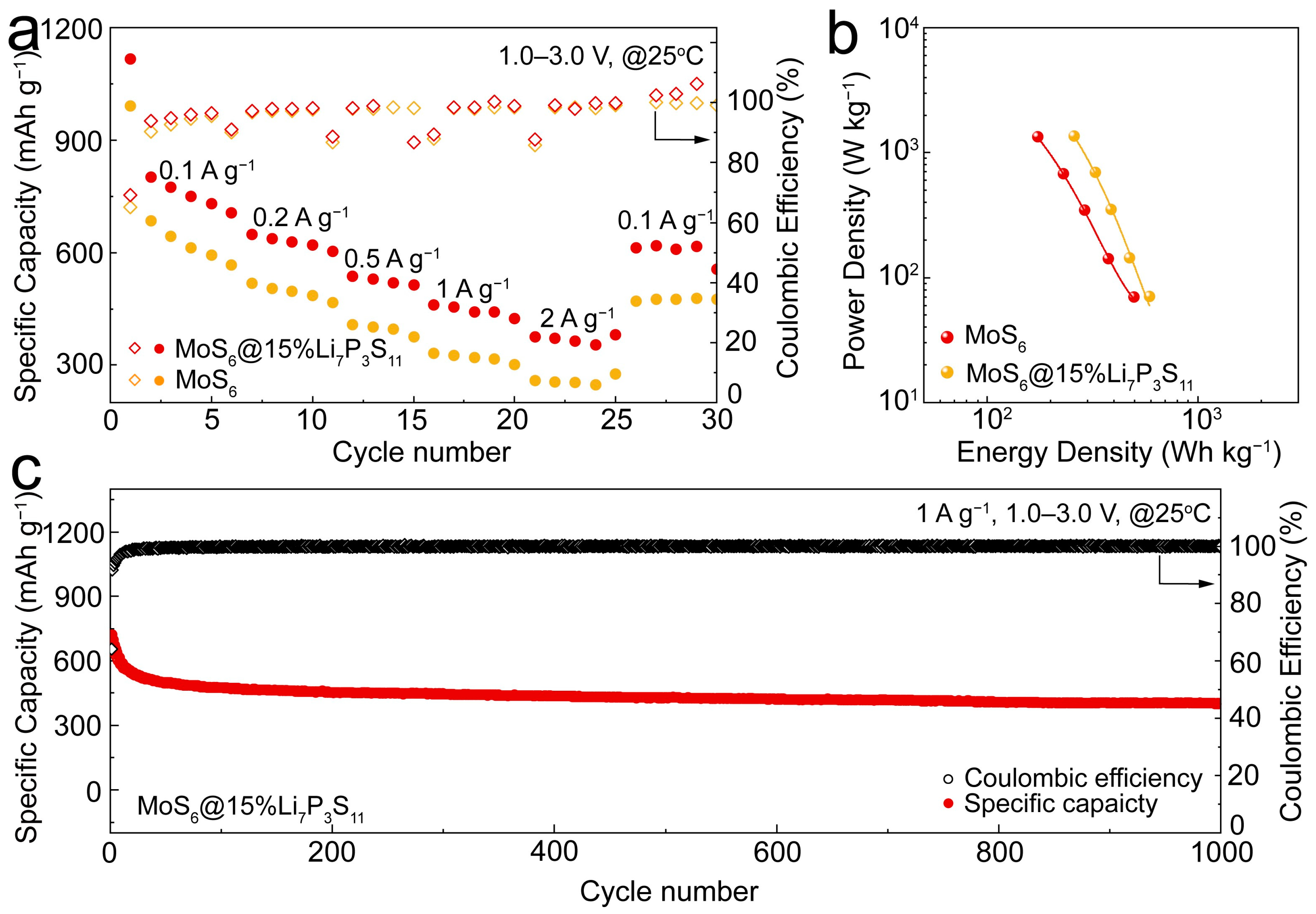
The rate capabilities of the MoS6 and MoS6@15%Li7P3S11 composite cathodes were measured under various current densities ranging from 0.1 to 2 A g−1 (Figure 5a). The MoS6@15%Li7P3S11 composite cathodes exhibited superior reversible discharge capacities of 801.5, 648.1, 536.3, 454.4, and 370.8 mAh g−1 under current densities of 0.1, 0.2, 0.5, 1, and 2 A g−1, respectively, while the MoS6 only exhibited reversible discharge capacities 683.9, 516.8, 407.7, 326.2, and 255.8 mAh g−1. The excellent rate capability of the MoS6@15%Li7P3S11 composite can be attributed to its enhanced ionic diffusivity, which led to improved electrochemical reaction kinetics. The Ragone plot shown in Figure 5b gives the relationship between the average power density and energy density. The power density of the MoS6 and MoS6@15%Li7P3S11 composite were calculated using the equation p o w e r   d e n s i t y = E D × m a c t i v e   m a t e r i a l s m c a t h o d e   l a y e r t , where ED is the energy density of the active materials, m is the loading weight of the active materials or the cathode layer, and t is the duration of the discharge process. The MoS6 and MoS6@15%Li7P3S11 composite numbers that were used in the energy density and power density calculations are listed in Tables S4 and S5. At current densities of 0.1 and 2.0 A g−1, the MoS6@15%Li7P3S11 composite cathodes delivered energy and power densities of 588 Wh kg−1 and 1358 W kg−1, respectively, based on the total cathode layer which is composed of the MoS6@15%Li7P3S11 composite, Li10GeP2S12, and super P. These values were significantly higher than the energy and power densities of 495.8 Wh kg−1 and 1332.2 W kg−1 exhibited by the MoS6 at the same respective current densities. The long-term cycling stability of the MoS6@15%Li7P3S11 composite cathodes at 1 A g−1 is further shown in Figure 5c, which shows that the cathodes exhibited a high reversible capacity of 400 mAh g−1 after 1000 cycles.
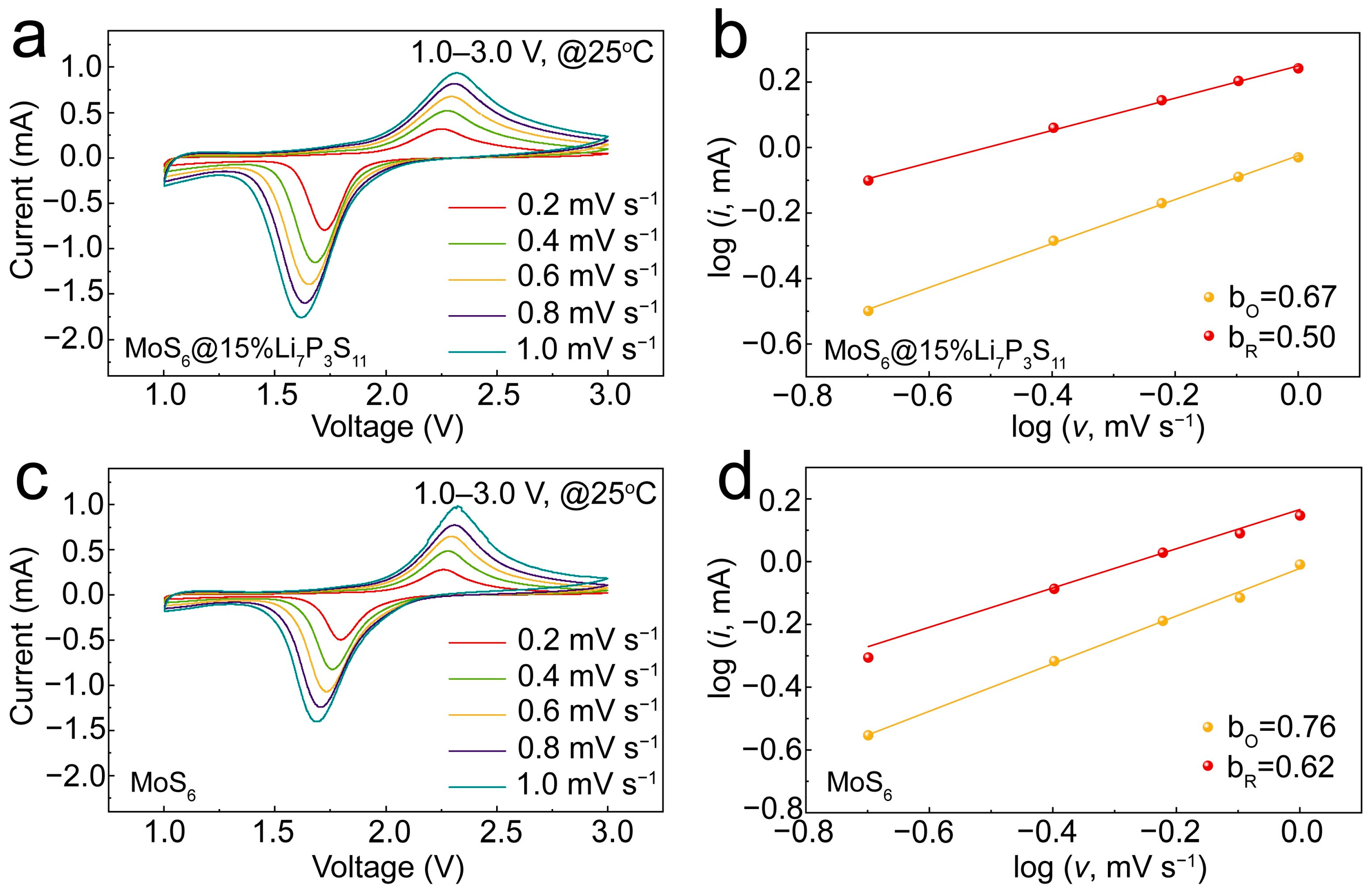
CV measurements were conducted to illustrate the electrochemical reaction kinetics. The relationship between the peak current (i) and the scan rate obeys the power law: i = a v b . The b-value is fitted using a log(v)-log(i) plot. A b-value of 1.0 indicates a surface-mediated mode, while a b-value of 0.5 indicates a diffusion-controlled mode. The CV curves shown in Figure 6a,c show similar shapes and gradually broadened redox peaks. At the same scan rate, the curve intensity of the MoS6@15%Li7P3S11 composite was higher than that of the MoS6, indicating that the MoS6@15%Li7P3S11 composite can maintain fast electrochemical kinetics with an increased scan rate. As shown in Figure 6b, the fitted b-values of the reduction peak and the oxidation peak were 0.50 and 0.67, respectively, for the MoS6@15%Li7P3S11 composite; these values are lower than the fitted b-values of 0.62 and 0.76 recorded for the MoS6 (Figure 6d), indicating that the electrochemical reaction kinetics are dominated by diffusion-controlled processes. This condition allows lithium ions to become fully intercalated and thereby realize high reversible capacity [17,29].
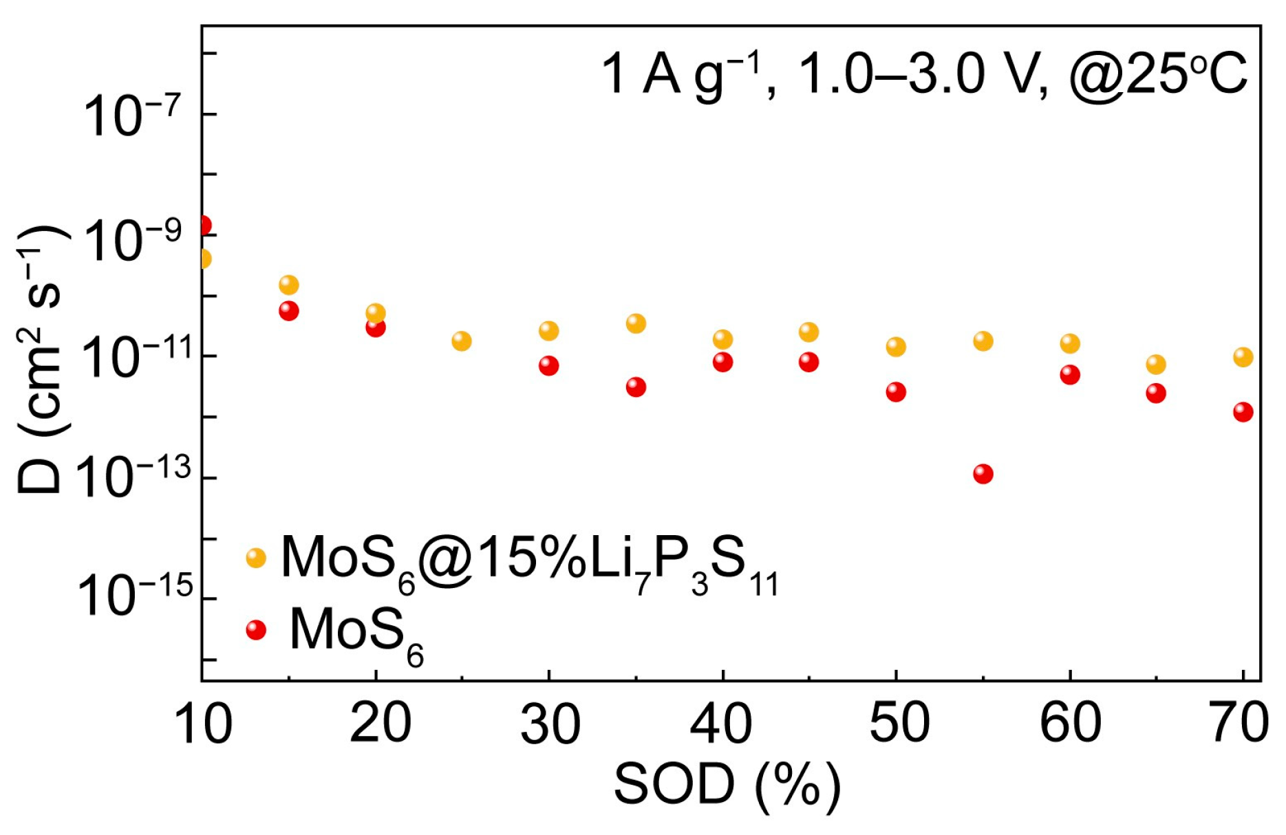
To further quantify the ionic transport kinetics of the Li/Li6PS5Cl/MoS6@15%Li7P3S11 and Li/Li6PS5Cl/MoS6 all-solid-state batteries, the GITT was used and calculated were made to determine the lithium ion diffusion coefficients at 1 A g−1 and 1.0–3.0 V. As is shown in Figure 7, the ion diffusion coefficient range of the MoS6@15%Li7P3S11 composite was calculated to be 10−11–10−10 cm2 s−1, which is higher than that of the MoS6 (10−12–10−11 cm2 s−1). Obviously, the ionic diffusivity of the MoS6@15%Li7P3S11 composite was enhanced significantly; this is beneficial for the rapid transportation of lithium ions and thus significantly improved the electrochemical performances related to high discharge capacity and rate capability.

4. Conclusions

In summary, the micro-sized MoS6 with high S 2 2 content demonstrated a high initial theoretical capacity of 1117 mAh g−1. After coating the MoS6 with Li7P3S11 solid electrolytes, the resulting MoS6@15%Li7P3S11 composite was able to achieve an improved ion diffusion coefficient range of 10−11–10−10 cm2 s−1, which was higher than the value of the MoS6 (10−12–10−11 cm2 s−1). The Li/Li6PS5Cl/MoS6@15%Li7P3S11 all-solid-sate lithium batteries showed a high initial discharge capacity of 1083.8 mAh g−1 at 0.1 A g−1 and a long cycle life of 1000 cycles at 1A g−1 and 25 °C. In addition, the MoS6@15%Li7P3S11 composite displayed a high energy density of 588 Wh kg−1 and a power density of 1358 W kg−1 based on the total cathode layer. This contribution provides a new sulfide-based cathode material with high specific capacity and a superior ion diffusion coefficient which has promising application potential for use in all-solid-state lithium batteries.

Supplementary Materials

The follow supporting information can be downloaded at: https://www.mdpi.com/article/10.3390/batteries9110560/s1, Figure S1: XRD pattern of (NH4)2Mo2S12; Figure S2: Cyclic performances of Li/Li6PS5Cl/MoS6 and Li/75%Li2S-24%P2S5-1%P2O5/Li10GeP2S12/MoS6 all-solid-state batteries under 0.2 A g−1; Figure S3: Cyclic performances of all-solid-state batteries with 50MoS6:50Li10GeP2S12, 40MoS6:50Li10GeP2S12:10Super P, and 40MoS6:40Li10GeP2S12:20Super P cathodes under 0.1 A g−1; Figure S4: Cyclic performances of MoS6@10%Li7P3S11, MoS6@15%Li7P3S11, and MoS6@20%Li7P3S11 cathodes under 0.1 A g−1; Table S1: Inductively coupled plasma emission spectrometer analysis of MoS6; Table S2: Electrochemical performances comparisons of various active materials in all-solid-state-batteries; Table S3: EIS fitting results of MoS6 and MoS6@15%Li7P3S11 under 0.1 A g−1 after 20 cycles; Table S4: MoS6 values used in energy density and power density calculations; Table S5: MoS6@15%Li7P3S11 composite values used in energy density and power density calculations.

Author Contributions

Conceptualization: X.Y.; methodology: M.C. and X.Y.; general experimental investigation and electrochemical analysis: M.C., M.Y., W.X., F.T. and G.L.; characterization: M.C.; supervision and research guidance: P.C., T.W. and X.Y.; funding acquisition: X.Y. All authors have read and agreed to the published version of the manuscript.

Funding

This work was supported by National Natural Science Foundation of China (Grant No. U1964205), the Jiangsu Provincial S&T Innovation Special Programme for Carbon Peak and Carbon Neutrality (Grant No. BE2022007), and the Youth Innovation Promotion Association CAS (Y2021080).

Data Availability Statement

The data presented in this study are available on request from the corresponding author. The data are not publicly available due to privacy policy.

Conflicts of Interest

The authors declare no conflict of interest.

References

  1. Zhao, W.G.; Zou, L.F.; Jia, H.P.; Zheng, J.M.; Wang, D.H.; Song, J.H.; Hong, C.Y.; Liu, R.; Xu, W.; Yang, Y.; et al. Optimized Al Doping Improves Both Interphase Stability and Bulk Structural Integrity of Ni-Rich NMC Cathode Materials. ACS Appl. Energy Mater. 2020, 3, 3369–3377. [Google Scholar] [CrossRef]
  2. Bruce, P.G.; Freunberger, S.A.; Hardwick, L.J.; Tarascon, J.M. Li-O2 and Li-S batteries with high energy storage. Nat. Mater. 2012, 11, 19–29. [Google Scholar] [CrossRef]
  3. Kato, Y.; Hori, S.; Saito, T.; Suzuki, K.; Hirayama, M.; Mitsui, A.; Yonemura, M.; Iba, H.; Kanno, R. High-power all-solid-state batteries using sulfide superionic conductors. Nat. Energy 2016, 1, 16030. [Google Scholar] [CrossRef]
  4. Yi, Y.K.; Hai, F.; Guo, J.Y.; Tian, X.L.; Zheng, S.T.; Wu, Z.D.; Wang, T.; Li, M.T. Progress and Prospect of Practical Lithium-Sulfur Batteries Based on Solid-Phase Conversion. Batteries 2023, 9, 27. [Google Scholar] [CrossRef]
  5. Shi, C.M.; Alexander, G.V.; O’Neill, J.; Duncan, K.; Godbey, G.; Wachsman, E.D. All-Solid-State Garnet Type Sulfurized Polyacrylonitrile/Lithium-Metal Battery Enabled by an Inorganic Lithium Conductive Salt and a Bilayer Electrolyte Architecture. ACS Energy Lett. 2023, 8, 1803–1810. [Google Scholar] [CrossRef]
  6. Kamaya, N.; Homma, K.; Yamakawa, Y.; Hirayama, M.; Kanno, R.; Yonemura, M.; Kamiyama, T.; Kato, Y.; Hama, S.; Kawamoto, K.; et al. A lithium superionic conductor. Nat. Mater. 2011, 10, 682–686. [Google Scholar] [CrossRef] [PubMed]
  7. Boulineau, S.; Courty, M.; Tarascon, J.M.; Viallet, V. Mechanochemical synthesis of Li-argyrodite Li6PS5X (X = Cl, Br, I) as sulfur-based solid electrolytes for all solid state batteries application. Solid State Ion. 2012, 221, 1–5. [Google Scholar] [CrossRef]
  8. Grayfer, E.D.; Pazhetnov, E.M.; Kozlova, M.N.; Artemkina, S.B.; Fedorov, V.E. Anionic Redox Chemistry in Polysulfide Electrode Materials for Rechargeable Batteries. ChemSusChem 2017, 10, 4805–4811. [Google Scholar] [CrossRef]
  9. Sakuda, A.; Ohara, K.; Fukuda, K.; Nakanishi, K.; Kawaguchi, T.; Arai, H.; Uchimoto, Y.; Ohta, T.; Matsubara, E.; Ogumi, Z.; et al. Amorphous Metal Polysulfides: Electrode Materials with Unique Insertion/Extraction Reactions. J. Am. Chem. Soc. 2017, 139, 8796–8799. [Google Scholar] [CrossRef]
  10. Yersak, T.A.; Macpherson, H.A.; Kim, S.C.; Le, V.D.; Kang, C.S.; Son, S.B.; Kim, Y.H.; Trevey, J.E.; Oh, K.H.; Stoldt, C.; et al. Solid State Enabled Reversible Four Electron Storage. Adv. Energy Mater. 2013, 3, 120–127. [Google Scholar] [CrossRef]
  11. Wang, T.S.; Hu, P.; Zhang, C.J.; Du, H.P.; Zhang, Z.H.; Wang, X.G.; Chen, S.G.; Xiong, J.W.; Cui, G.L. Nickel Disulfide-Graphene Nanosheets Composites with Improved Electrochemical Performance for Sodium Ion Battery. ACS Appl. Mater Interfaces 2016, 8, 7811–7817. [Google Scholar] [CrossRef]
  12. Arsentev, M.; Missyul, A.; Petrov, A.V.; Hammouri, M. TiS3 Magnesium Battery Material: Atomic-Scale Study of Maximum Capacity and Structural Behavior. J. Phys. Chem. C 2017, 121, 15509–15515. [Google Scholar] [CrossRef]
  13. Dong, S.W.; Sheng, L.; Wang, L.; Liang, J.; Zhang, H.; Chen, Z.H.; Xu, H.; He, X.M. Challenges and Prospects of All-Solid-State Electrodes for Solid-State Lithium Batteries. Adv. Funct. Mater. 2023, 2304371. [Google Scholar] [CrossRef]
  14. Chong, P.D.; Zhou, Z.W.; Wang, K.H.; Zhai, W.H.; Li, Y.F.; Wang, J.B.; Wei, M.D. The Stabilizing of 1T-MoS2 for All-Solid-State Lithium-Ion Batteries. Batteries 2023, 9, 26. [Google Scholar] [CrossRef]
  15. Wang, Y.F.; Goikolea, E.; de Larramendi, I.R.; Lanceros-Méndez, S.; Zhang, Q. Recycling methods for different cathode chemistries—A critical review. J. Energy Storage 2022, 56, 106053. [Google Scholar] [CrossRef]
  16. Shchegolkov, A.V.; Komarov, F.F.; Lipkin, M.S.; Milchanin, O.V.; Parfimovich, I.D.; Shchegolkov, A.V.; Semenkova, A.V.; Velichko, A.V.; Chebotov, K.D.; Nokhaeva, V.A. Synthesis and Study of Cathode Materials Based on Carbon Nanotubes for Lithium-Ion Batteries. Inorg. Mater. Appl. Res. 2021, 12, 1281–1287. [Google Scholar] [CrossRef]
  17. Zhang, Q.; Ding, Z.G.; Liu, G.Z.; Wan, H.L.; Mwizerwa, J.P.; Wu, J.H.; Yao, X.Y. Molybdenum trisulfide based anionic redox driven chemistry enabling high-performance all-solid-state lithium metal batteries. Energy Storage Mater. 2019, 23, 168–180. [Google Scholar] [CrossRef]
  18. Wu, F.X.; Yushin, G. Conversion cathodes for rechargeable lithium and lithium-ion batteries. Energy Environ. Sci. 2017, 10, 435–459. [Google Scholar] [CrossRef]
  19. Xu, R.C.; Wang, X.L.; Zhang, S.Z.; Xia, Y.; Xia, X.H.; Wu, J.B.; Tu, J.P. Rational coating of Li7P3S11 solid electrolyte on MoS2 electrode for all-solid-state lithium ion batteries. J. Power Sources 2018, 374, 107–112. [Google Scholar] [CrossRef]
  20. Ye, H.; Ma, L.; Zhou, Y.; Wang, L.; Han, N.; Zhao, F.; Deng, J.; Wu, T.; Li, Y.; Lu, J. Amorphous MoS3 as the sulfur-equivalent cathode material for room-temperature Li-S and Na-S batteries. Proc. Natl. Acad. Sci. USA 2017, 114, 13091–13096. [Google Scholar] [CrossRef]
  21. Yao, X.; Liu, D.; Wang, C.; Long, P.; Peng, G.; Hu, Y.S.; Li, H.; Chen, L.; Xu, X. High-Energy All-Solid-State Lithium Batteries with Ultralong Cycle Life. Nano Lett. 2016, 16, 7148–7154. [Google Scholar] [CrossRef] [PubMed]
  22. Ye, H.L.; Wang, L.; Deng, S.; Zeng, X.Q.; Nie, K.Q.; Duchesne, P.N.; Wang, B.; Liu, S.; Zhou, J.H.; Zhao, F.P.; et al. Amorphous MoS3 Infiltrated with Carbon Nanotubes as an Advanced Anode Material of Sodium-Ion Batteries with Large Gravimetric, Areal, and Volumetric Capacities. Adv. Energy Mater. 2017, 7, 160102. [Google Scholar] [CrossRef]
  23. Wang, X.; Du, K.; Wang, C.; Ma, L.; Zhao, B.; Yang, J.; Li, M.; Zhang, X.X.; Xue, M.; Chen, J. Unique Reversible Conversion-Type Mechanism Enhanced Cathode Performance in Amorphous Molybdenum Polysulfide. ACS Appl. Mater. Interfaces 2017, 9, 38606–38611. [Google Scholar] [CrossRef] [PubMed]
  24. Horner, J.S.; Whang, G.; Ashby, D.S.; Kolesnichenko, I.V.; Lambert, T.N.; Dunn, B.S.; Talin, A.A.; Roberts, S.A. Electrochemical Modeling of GITT Measurements for Improved Solid-State Diffusion Coefficient Evaluation. ACS Appl. Energy Mater. 2021, 4, 11460–11469. [Google Scholar] [CrossRef]
  25. Shen, Z.; Cao, L.; Rahn, C.D.; Wang, C.Y. Least Squares Galvanostatic Intermittent Titration Technique (LS-GITT) for Accurate Solid Phase Diffusivity Measurement. J. Electrochem. Soc. 2013, 160, A1842–A1846. [Google Scholar] [CrossRef]
  26. Mabayoje, O.; Wygant, B.R.; Wang, M.; Liu, Y.; Mullins, C.B. Sulfur-Rich MoS6 as an Electrocatalyst for the Hydrogen Evolution Reaction. ACS Appl. Energy Mater. 2018, 1, 4453–4458. [Google Scholar] [CrossRef]
  27. Tran, P.D.; Tran, T.V.; Orio, M.; Torelli, S.; Truong, Q.D.; Nayuki, K.; Sasaki, Y.; Chiam, S.Y.; Yi, R.; Honma, I.; et al. Coordination polymer structure and revisited hydrogen evolution catalytic mechanism for amorphous molybdenum sulfide. Nat. Mater. 2016, 15, 640–646. [Google Scholar] [CrossRef]
  28. Huang, J. Diffusion impedance of electroactive materials, electrolytic solutions and porous electrodes: Warburg impedance and beyond. Electrochim. Acta 2018, 281, 170–188. [Google Scholar] [CrossRef]
  29. Li, W.B.; Huang, J.F.; Cao, L.Y.; Feng, L.L.; Yao, C.Y. Controlled construction of 3D self-assembled VS4 nanoarchitectures as high-performance anodes for sodium-ion batteries. Electrochim. Acta 2018, 274, 334–342. [Google Scholar] [CrossRef]
Figure 1. Schematic diagram of procedure for preparing MoS6@15%Li7P3S11 composite.
Batteries 09 00560 g001
Figure 2. (a) XRD patterns of MoS6 and MoS6@15%Li7P3S11 composite. (b) Raman spectra of MoS6 and MoS6@15%Li7P3S11 composite.
Batteries 09 00560 g002
Figure 3. SEM images of (a) MoS6 and (b) MoS6@15% Li7P3S11, EDS mapping of (c) MoS6@15%Li7P3S11 composite, TEM images of (d) MoS6 and (e) MoS6@15% Li7P3S11, and HRTEM images of (f) MoS6@15% Li7P3S11.
Batteries 09 00560 g003
Figure 4. CV curves of (a) MoS6 and (b) MoS6@15%Li7P3S11 composite; galvanostatic discharge/charge profiles of (c) MoS6 and (d) MoS6@15%Li7P3S11 composite cathodes at 0.1 A g−1; (e) cyclic performances of MoS6 and MoS6@15%Li7P3S11 composite at 0.1 A g−1 within 1.0–3.0 V (the solid circles represent discharge capacities); (f) Nyquist plots and equivalent circuit diagram of MoS6 and MoS6@15%Li7P3S11 composite cathodes after 1st and 20th cycles at 0.1 A g−1 within 1.0–3.0 V.
Batteries 09 00560 g004
Figure 5. (a) Rate performances of MoS6 and MoS6@15%Li7P3S11 composite under different current densities. (b) Ragone plot deduced from the rate performances shown in (a). (c) Long-term cyclic performance of MoS6@15%Li7P3S11 composite at 1 A g−1.
Batteries 09 00560 g005
Figure 6. CV curves at different scan rates for (a) MoS6@15%Li7P3S11 composite and (c) MoS6. The log (peak current) vs. log (scan rate) fitted plots at reduction and oxidation peaks of (b) MoS6@15%Li7P3S11 composite and (d) MoS6.
Batteries 09 00560 g006
Figure 7. GITT plot of Li/Li6PS5Cl/MoS6@15%Li7P3S11 composite and Li/Li6PS5Cl/MoS6 all-solid-state lithium batteries.
Batteries 09 00560 g007
Disclaimer/Publisher’s Note: The statements, opinions and data contained in all publications are solely those of the individual author(s) and contributor(s) and not of MDPI and/or the editor(s). MDPI and/or the editor(s) disclaim responsibility for any injury to people or property resulting from any ideas, methods, instructions or products referred to in the content.

