
Enabling LVRT Compliance of Electrolyzer Systems Using Energy Storage Technologies


Abstract
:
1. Introduction
2. Characterization of System
2.1. Electrolyzer Module
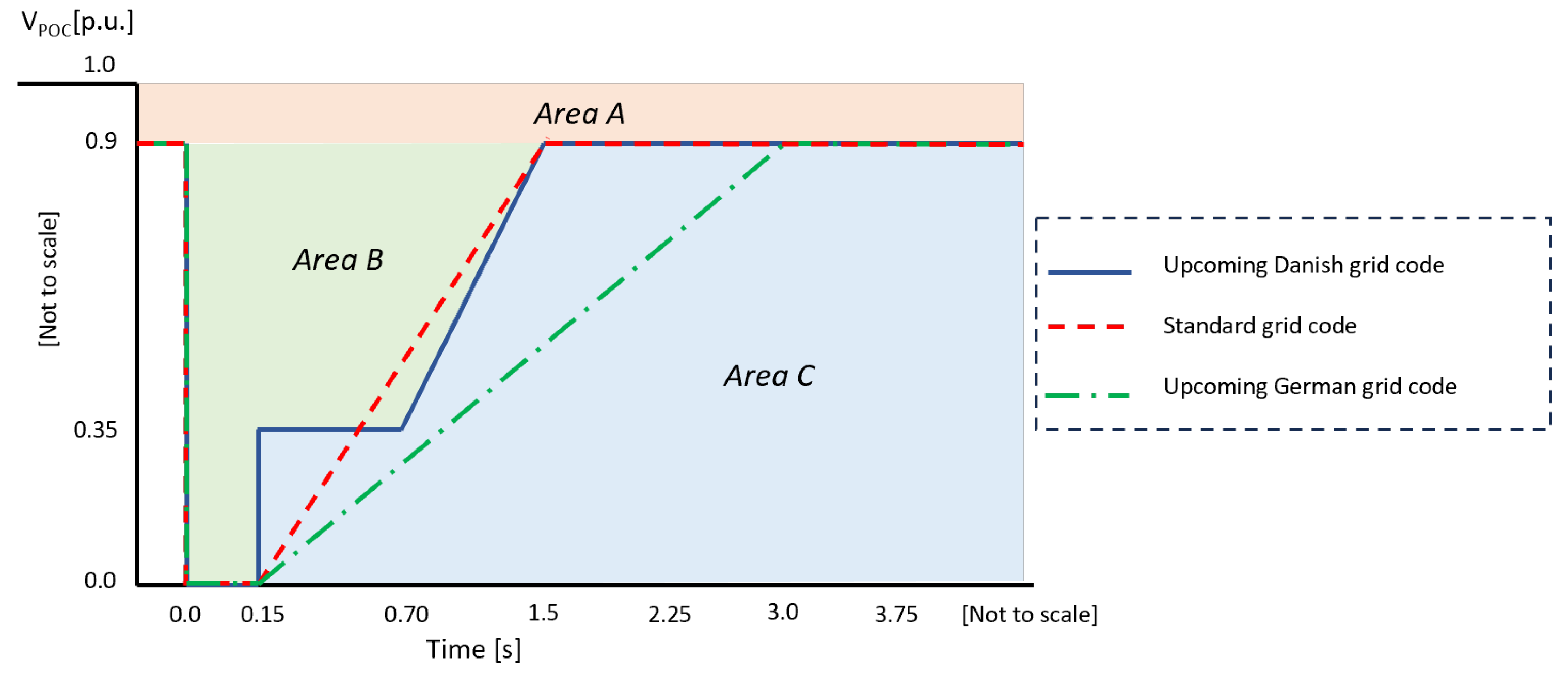
2.2. LVRT Profiles
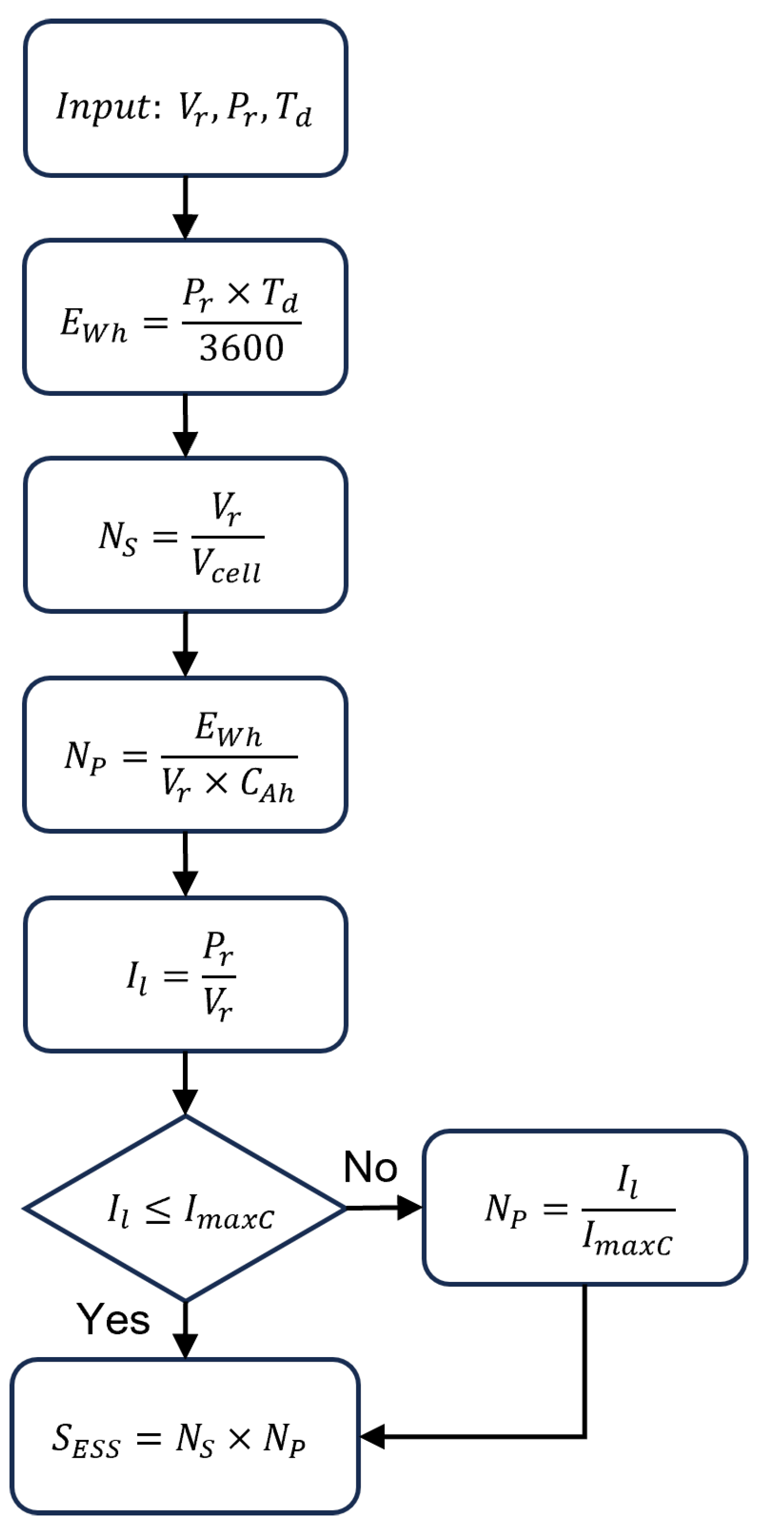
2.3. Methodology for ESS Sizing
- Step 1:
- For a given time duration () and the rated power (), the total energy required by the electrolyzer stack can be calculated as:where is the energy in watt-hours, and is the time duration in seconds during which the ESS needs to supply power to the electrolyzer.
- Step 2:
- The required number of series-connected cells () of the ESS is:where is the rated voltage of the electrolyzer, and is the nominal voltage of a unit cell of the ESS.
- Step 3:
- The number of parallel strings () can be calculated as:where is the unit cell capacity in ampere-hour. Essentially, the number of parallel strings defines the discharge current rate of the cells. Thus, if the obtained parallel strings value does not satisfy the cell’s maximum discharge current limit, the value of must be re-calculated following the subsequent steps. This will result in an over-sized ESS with plenty of energy remaining in the storage system even after fulfilling the power demand for the time duration .
- Step 4:
- The load current of the electrolyzer system is given by:
- Step 5:
- For a given maximum continuous discharge current () of the cell, the number of parallel strings of the ESS can be calculated as:
3. ESS Technologies
3.1. Lithium-Ion Batteries
3.2. Supercapacitors
3.3. Lithium-Ion Capacitors
4. Results and Discussion
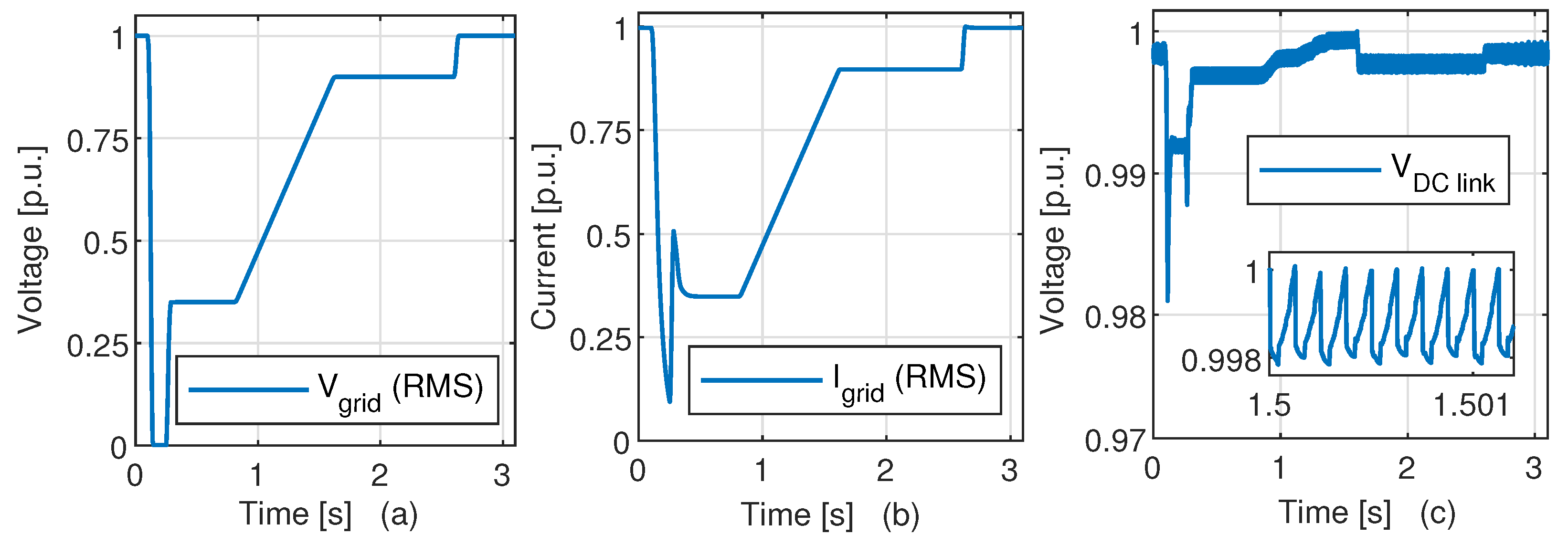
4.1. AFE Response during LVRT
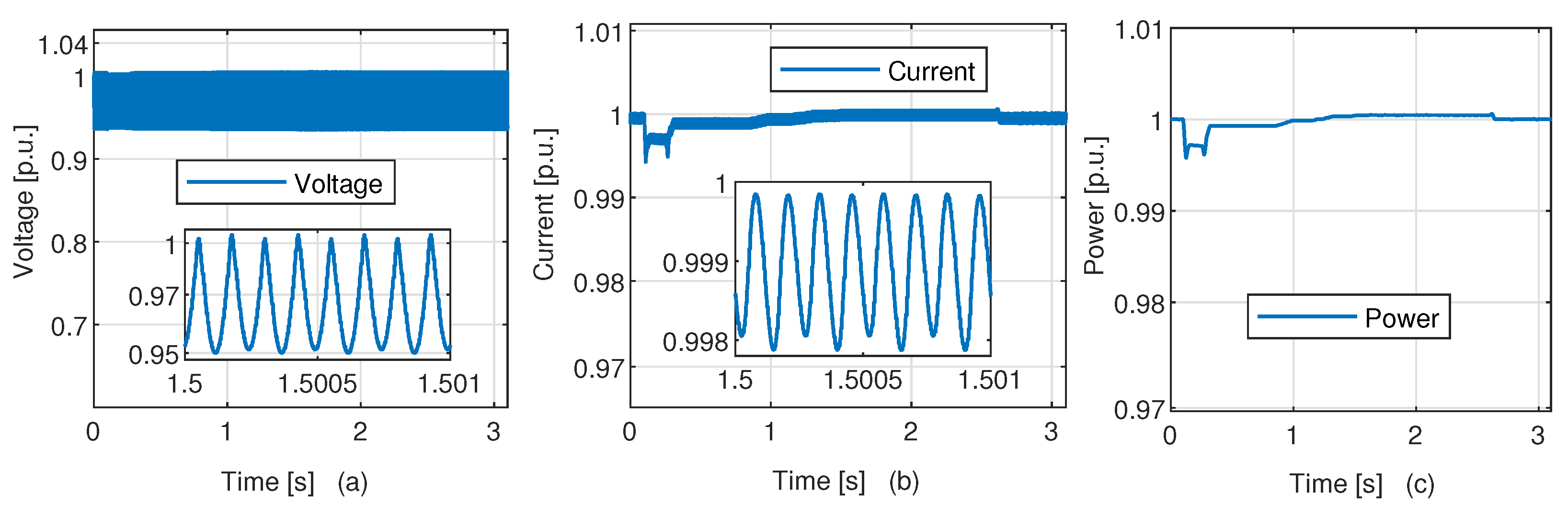
4.2. Electrolyzer Response during LVRT
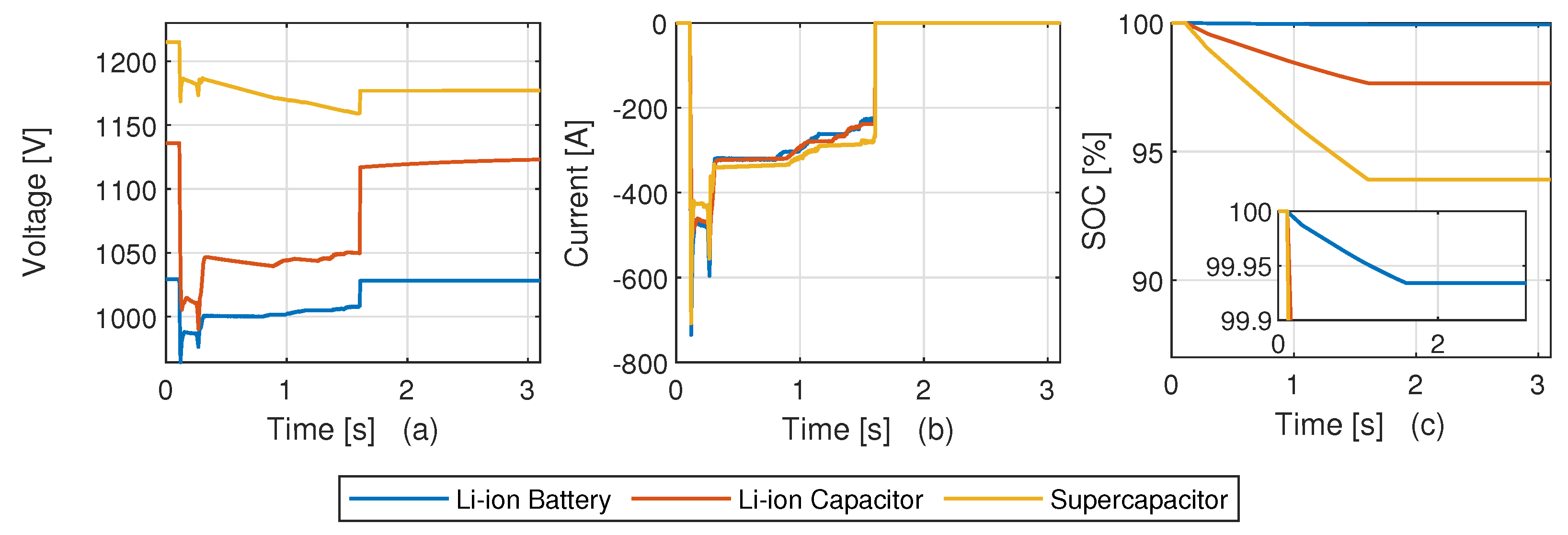
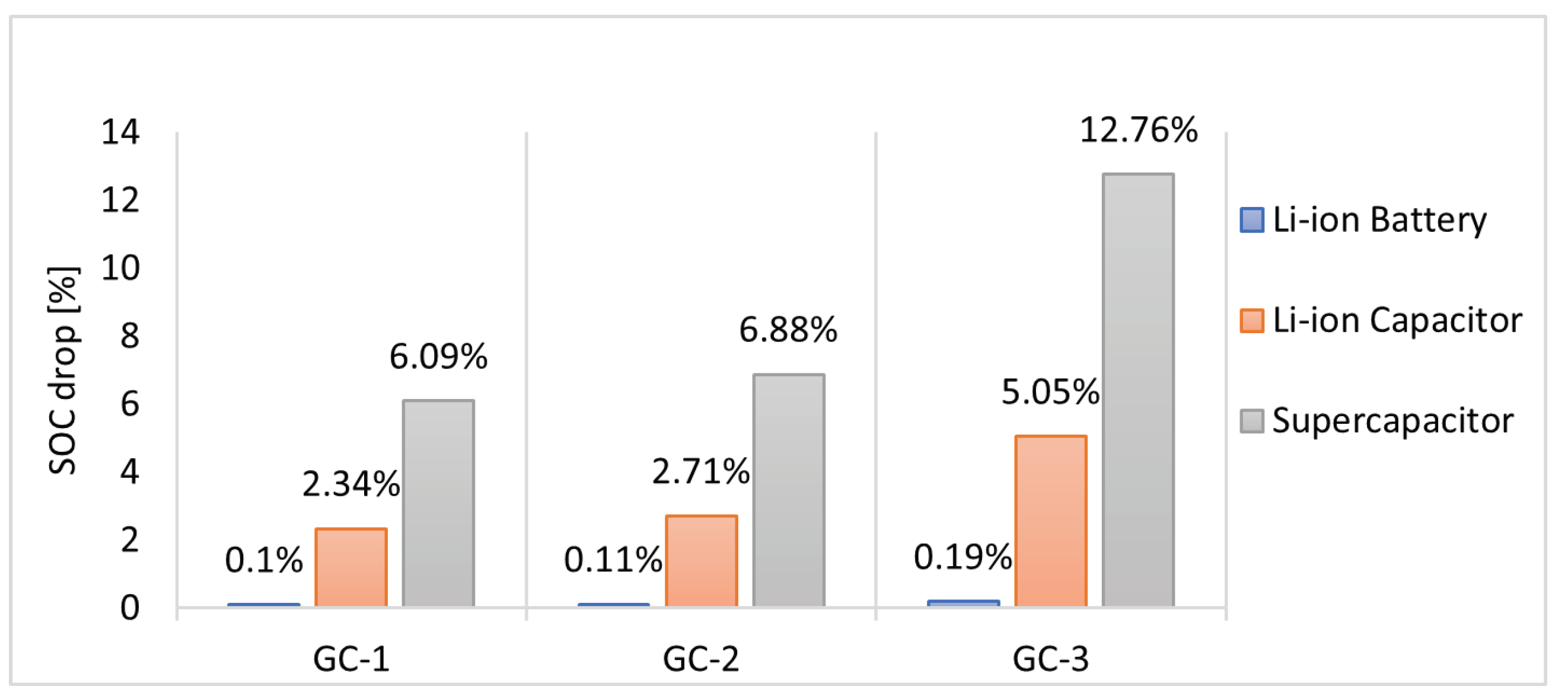
4.3. ESS Response during LVRT
4.4. Techno-Economic Analysis
5. Conclusions
Author Contributions
Funding
Acknowledgments
Conflicts of Interest
References
- Agency, I.R.E. What Are the Latest Trends in Renewable Energy? Available online: https://www.irena.org/Data/View-data-by-topic/Capacity-and-Generation/Statistics-Time-Series (accessed on 2 September 2023).
- Mazzeo, D.; Herdem, M.S.; Matera, N.; Wen, J.Z. Green hydrogen production: Analysis for different single or combined large-scale photovoltaic and wind renewable systems. Renew. Energy 2022, 200, 360–378. [Google Scholar] [CrossRef]
- Navarro, R.; Sanchez-Sanchez, M.; Alvarez-Galvan, M.; Del Valle, F.; Fierro, J. Hydrogen production from renewable sources: Biomass and photocatalytic opportunities. Energy Environ. Sci. 2009, 2, 35–54. [Google Scholar] [CrossRef]
- Dawood, F.; Anda, M.; Shafiullah, G. Hydrogen production for energy: An overview. Int. J. Hydrogen Energy 2020, 45, 3847–3869. [Google Scholar] [CrossRef]
- Kumar, S.S.; Lim, H. An overview of water electrolysis technologies for green hydrogen production. Energy Rep. 2022, 8, 13793–13813. [Google Scholar] [CrossRef]
- Felseghi, R.A.; Carcadea, E.; Raboaca, M.S.; Trufin, C.N.; Filote, C. Hydrogen fuel cell technology for the sustainable future of stationary applications. Energies 2019, 12, 4593. [Google Scholar] [CrossRef]
- Aminudin, M.; Kamarudin, S.; Lim, B.; Majilan, E.; Masdar, M.; Shaari, N. An overview: Current progress on hydrogen fuel cell vehicles. Int. J. Hydrogen Energy 2023, 48, 4371–4388. [Google Scholar] [CrossRef]
- Sharma, S.; Ghoshal, S.K. Hydrogen the future transportation fuel: From production to applications. Renew. Sustain. Energy Rev. 2015, 43, 1151–1158. [Google Scholar] [CrossRef]
- European Comission. Climate Neutrality, 2050 Long-Term Strategy. Available online: https://climate.ec.europa.eu/eu-action/climate-strategies-targets/2050-long-term-strategy-en (accessed on 10 September 2023).
- European Comission. Denmark’s Long-Term Strategy—European Commission. Available online: https://ec.europa.eu/clima/sites/lts/lts-dk-en.pdf (accessed on 10 September 2023).
- Younas, M.; Shafique, S.; Hafeez, A.; Javed, F.; Rehman, F. An overview of hydrogen production: Current status, potential, and challenges. Fuel 2022, 316, 123317. [Google Scholar] [CrossRef]
- European Comission. State Aid: Commission Approves up to €5.4 Billion of Public Support by Fifteen MEMBER States for an Important Project of Common European Interest in the Hydrogen Technology Value Chain. Available online: https://ec.europa.eu/commission/presscorner/detail/en/ip-22-4544 (accessed on 10 September 2023).
- Denmark’s Energy Islands. Available online: https://ens.dk/en/our-responsibilities/energy-islands/denmarks-energy-islands (accessed on 10 September 2023).
- ENERGYNET. Connection Requirements in Relation to Large PTX Systems to Transmission Networks. Available online: https://en.energinet.dk/Electricity/Rules-and-Regulations/Regulations-for-grid-connection/ (accessed on 10 September 2023).
- Guilbert, D.; Collura, S.M.; Scipioni, A. DC/DC converter topologies for electrolyzers: State-of-the-art and remaining key issues. Int. J. Hydrogen Energy 2017, 42, 23966–23985. [Google Scholar] [CrossRef]
- Yodwong, B.; Guilbert, D.; Phattanasak, M.; Kaewmanee, W.; Hinaje, M.; Vitale, G. AC-DC converters for electrolyzer applications: State of the art and future challenges. Electronics 2020, 9, 912. [Google Scholar] [CrossRef]
- Chen, M.; Chou, S.F.; Blaabjerg, F.; Davari, P. Overview of power electronic converter topologies enabling large-scale hydrogen production via water electrolysis. Appl. Sci. 2022, 12, 1906. [Google Scholar] [CrossRef]
- Zhao, W.; Nielsen, M.R.; Kjær, M.; Iov, F.; Nielsen, S.M. Grid integration of a 500 kW alkaline electrolyzer system for harmonic analysis and robust control. E-Prime Electr. Eng. Electron. Energy 2023, 5, 100217. [Google Scholar] [CrossRef]
- Kim, T.; Song, W.; Son, D.Y.; Ono, L.K.; Qi, Y. Lithium-ion batteries: Outlook on present, future, and hybridized technologies. J. Mater. Chem. A 2019, 7, 2942–2964. [Google Scholar] [CrossRef]
- Saha, P.; Dey, S.; Khanra, M. Modeling and state-of-charge estimation of supercapacitor considering leakage effect. IEEE Trans. Ind. Electron. 2019, 67, 350–357. [Google Scholar] [CrossRef]
- Soltani, M.; Beheshti, S.H. A comprehensive review of li-ion capacitor:development, modelling, thermal management applications. J. Energy Storage 2021, 34, 102019. [Google Scholar] [CrossRef]
- Hazari, M.R.; Jahan, E.; Mannan, M.A.; Tamura, J. Coordinated control scheme of battery storage system to augment LVRT capability of SCIG-based wind turbines and frequency regulation of hybrid power system. Electronics 2020, 9, 239. [Google Scholar] [CrossRef]
- Gayathri, T.; Ananth, D.; Kumar, G.N.; Sivanagaraju, G. Enhancement in dynamic and LVRT behaviour of an EFOC controlled DFIG with integrated Battery Energy Storage System. In Proceedings of the 2013 Annual IEEE India Conference (INDICON), Mumbai, India, 13–15 December 2013; pp. 1–6. [Google Scholar]
- Huy, T.N.; Le Hanh, D.; Takano, H.; Duc, T.N. Cooperative LVRT control for protecting PMSG-based WTGs using battery energy storage system. Energy Rep. 2023, 9, 590–598. [Google Scholar]
- Jin, C.; Wang, P. Enhancement of low voltage ride-through capability for wind turbine driven DFIG with active crowbar and battery energy storage system. In Proceedings of the IEEE PES General Meeting, Minneapolis, MN, USA, 25–29 July 2010; pp. 1–8. [Google Scholar]
- Kalyan, R.; Murali, V.; Pitchaimuthu, R. Coordinate Control of Grid Power, Battery SoC and LVRT Protection in Single VSC Tied DFIG. Distrib. Gener. Altern. Energy J. 2022, 37, 587–608. [Google Scholar] [CrossRef]
- Rai, R.; Singh, B. Converter Control During Low Voltage Ride Through Operation for Grid-Interfaced Solar PV Battery Assisted System. IEEE Trans. Ind. Electron. 2022, 70, 9181–9191. [Google Scholar] [CrossRef]
- Raphel, B.; Johannes, W.; Volker, S.; Christian, S.; Stanko, J.; Hartmut, P. Requirements for Power-to-Gas Units. In Proceedings of the 22nd Wind and Solar Integration Workshop, Copenhagen, Denmark, 26–28 September 2023. [Google Scholar]
- Kabsha, M.M.; Rather, Z.H. Advanced LVRT control scheme for offshore wind power plant. IEEE Trans. Power Deliv. 2021, 36, 3893–3902. [Google Scholar] [CrossRef]
- Energynet. Regulations for Grid Connection. Available online: https://en.energinet.dk/Electricity/Rules-and-Regulations/Regulations-for-grid-connection/ (accessed on 2 September 2023).
- Bansal, S.; Nambisan, P.; Saha, P.; Khanra, M. Effect of supercapacitor modelling and unit cell capacitance selection towards economic sizing of energy storage system in electric vehicle. J. Energy Storage 2022, 51, 104517. [Google Scholar] [CrossRef]
- Pankaj, S.; Mahdi, S.; Stig, M.N.; Daniel-Ioan, S. A Model Predictive Control Approach for Lithium-ion Capacitor Optimal Charging. In Proceedings of the 2023 The 25th European Conference on Power Electronics and Applications (EPE’23 ECCE Europe), Aalborg, Denmark, 4–8 September 2023; pp. 1–6. [Google Scholar]
- BloombergNEF (BNEF). Near-Term Lithium-Ion Battery Cell and Pack Price Forecast. Available online: https://about.bnef.com/blog/top-10-energy-storage-trends-in-2023/ (accessed on 2 September 2023).
- Roy, P.K.S.; Karayaka, H.B.; He, J.; Yu, Y.H. Economic comparison between battery and supercapacitor for hourly dispatching wave energy converter power. In Proceedings of the 2020 52nd North American Power Symposium (NAPS), Tempe, AZ, USA, 11–13 April 2021; pp. 1–6. [Google Scholar]


| Parameter | Li-Ion Battery | Li-Ion Capacitor | Supercapacitor |
|---|---|---|---|
| Nominal voltage [V] | 3.2 | 3 | 2 |
| Voltage range [V] | 2.5–3.65 | 2.2–3.8 | 1.35–2.7 |
| Capacity [Ah] | 180 | 0.93 | 1.125 |
| Max. continuous current [A] | 720 | 100 | 210 |
| Specific power [W/kg] | 205 | 4 × 10 | 5.9 × 10 |
| Specific energy [Wh/kg] | 102 | 24 | 6 |
| Mass [kg] | 5.6 | 0.11 | 0.51 |
| Volume [m] | 36 × 10 | 1.11 × 10 | 3.95 × 10 |
| Energy Storage Technology | Equivalent Circuit Model | Mathematical Representation |
|---|---|---|
| Li-ion battery | 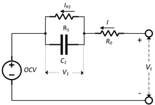 | |
| Supercapacitor |  | |
| Li-ion capacitor |  |
| Technology | Energy Capacity [kWh] | ||
|---|---|---|---|
| Li-ion battery | 288 | 1 | 162.4 |
| Li-ion capacitor | 300 | 6 | 5.022 |
| Supercapacitor | 450 | 3 | 3.037 |
| Parameter | Li-Ion Battery | Li-Ion Capacitor | Supercapacitor |
|---|---|---|---|
| Price ($/kWh) | 300 | 37,167 | 2500 |
| Installation cost ($) | 48,720 | 186,650 | 7600 |
| Mass (kg) | 1612.8 | 198 | 688.5 |
| Volume (m) | 1.03 | 0.2 | 0.54 |
| Max. backup duration (s) | 1160.8 | 36.15 | 21.86 |
| Cycle life (cycles) | ∼2000 | ∼300,000 | ∼1,000,000 |
Disclaimer/Publisher’s Note: The statements, opinions and data contained in all publications are solely those of the individual author(s) and contributor(s) and not of MDPI and/or the editor(s). MDPI and/or the editor(s) disclaim responsibility for any injury to people or property resulting from any ideas, methods, instructions or products referred to in the content. |
© 2023 by the authors. Licensee MDPI, Basel, Switzerland. This article is an open access article distributed under the terms and conditions of the Creative Commons Attribution (CC BY) license (https://creativecommons.org/licenses/by/4.0/).
Share and Cite
Saha, P.; Zhao, W.; Stroe, D.-I.; Iov, F.; Munk-Nielsen, S. Enabling LVRT Compliance of Electrolyzer Systems Using Energy Storage Technologies. Batteries 2023, 9, 527. https://doi.org/10.3390/batteries9110527
Saha P, Zhao W, Stroe D-I, Iov F, Munk-Nielsen S. Enabling LVRT Compliance of Electrolyzer Systems Using Energy Storage Technologies. Batteries. 2023; 9(11):527. https://doi.org/10.3390/batteries9110527
Chicago/Turabian StyleSaha, Pankaj, Weihao Zhao, Daniel-Ioan Stroe, Florin Iov, and Stig Munk-Nielsen. 2023. "Enabling LVRT Compliance of Electrolyzer Systems Using Energy Storage Technologies" Batteries 9, no. 11: 527. https://doi.org/10.3390/batteries9110527
APA StyleSaha, P., Zhao, W., Stroe, D.-I., Iov, F., & Munk-Nielsen, S. (2023). Enabling LVRT Compliance of Electrolyzer Systems Using Energy Storage Technologies. Batteries, 9(11), 527. https://doi.org/10.3390/batteries9110527