Article

Effect of Carrier Film Phase Conversion Time on Polyacrylate Polymer Electrolyte Properties in All-Solid-State LIBs

1
MIIT Key Laboratory of Critical Materials Technology for New Energy Conversion and Storage, State Key Lab of Urban Water Resources and Environment, Harbin Institute of Technology, School of Chemistry and Chemical Engineering, Harbin 150001, China
2
Beijing Guodian Ruixin Technology Co., Ltd., Beijing 100085, China
3
Institute of Materials Physical Chemistry, Engineering Research Center of Environment-Friendly Functional Materials, Ministry of Education, Huaqiao University, Xiamen 361021, China
4
Shandong Yellow Sea Institute of Science and Technology Innovation, Headquarters Base No. 1, Qingdao Road, Rizhao 276800, China
5
Zhuhai Zhongli New Energy Sci-Tech Co., Ltd., Zhuhai 519000, China
*
Authors to whom correspondence should be addressed.
Batteries 2023, 9(9), 471; https://doi.org/10.3390/batteries9090471
Submission received: 4 August 2023 / Revised: 2 September 2023 / Accepted: 8 September 2023 / Published: 19 September 2023

Abstract

:
To optimize the preparation process of polymer electrolytes by in situ UV curing and improve the performance of polymer electrolytes, we investigated the effect of carrier film phase conversion time on the properties of polymer electrolyte properties in all-solid-state LIBs. We compared several carrier films with phase conversion times of 24 h, 32 h, 40 h, and 48 h. Then, the physical properties of the polymer electrolytes were characterized and the properties of the polymer electrolytes were further explored. It was concluded that the carrier membrane with a phase transition time of 40 h and the prepared electrolyte had the best performance. The ionic conductivity of the sample was 1.02 × 10⁻³ S/cm at 25 °C and 3.42 × 10⁻³ S/cm at 60 °C. At its best cycle performance, it had the highest discharge-specific capacity of 155.6 mAh/g, and after 70 cycles, the discharge-specific capacity was 152.4 mAh/g, with a capacity retention rate of 98% and a discharge efficiency close to 100%. At the same time, the thermogravimetric curves showed that the samples prepared by this process had good thermal stability which can meet the various requirements of lithium-ion batteries.

1. Introduction

Lithium-ion batteries with a high energy density and good cycle stability are widely used in portable devices, electric vehicles, and smart grids. Unfortunately, the liquid electrolytes used in the market for power batteries pose potential safety problems due to their low flash point [1]. As researchers pursue higher-energy power batteries, safety concerns have also emerged. As technology continues to evolve and application requirements continue to improve, lithium-ion batteries face several key challenges, such as the market demand for higher safety and energy density [2,3]. Traditional lithium-ion battery technology faces bottleneck problems in these aspects, so it is urgent to develop a new generation of lithium-ion battery technology [4,5].
All solid polymer electrolytes have the advantage of a wide electrochemical window, good thermal stability, low packaging requirements, and high production efficiency; they can significantly improve the operating conditions and safety of lithium-ion batteries in extreme environments [6,7]. The main challenge in achieving all-solid-state lithium batteries is to obtain solid electrolytes with considerable ionic conductivity [8,9]. The interface impedance between the solid electrolyte and the electrode also needs to be reduced. The plastic crystal solid-state polymer electrolyte prepared with succinonitrile (SN) not only overcomes the above shortcomings but also has good ionic conductivity at ambient temperature, showing a large electrochemical window, which greatly expands the application range of lithium-ion batteries [10,11]. At the same time, it has excellent electrochemical performance and no liquid exists, therefore, it shows excellent safety [12,13].
To further improve the performance of polymer electrolytes, the preparation process of the electrolyte carrier membrane is further optimized. The essence of the electrolyte carrier membrane is the PVDF-HFP phase conversion membrane [14,15]. In 1963, Leob and Sourirajan invented the phase conversion process for the first time and produced reverse osmosis membranes with asymmetric structures [16]. Thus, the polymer separation membrane was provided with an industrial value [17]. Since then, the phase conversion process has been widely studied and applied, gradually becoming the main flow method of polymerization separation membrane production [2,18].
The so-called phase conversion membrane is used to prepare a homogeneous polymer solution of a certain composition, which changes the thermodynamic state of the solution through certain physical methods, so that phase separation occurs from the homogeneous polymer solution and finally transforms it into a three-dimensional macromolecular network-type gel structure [19,20]. In this gel structure, the polymer is in a continuous phase and the dispersed phase is the pore structure left after the elution of the dilute polymer phase [21].
In general, when the casting liquid enters the gel bath and solidifies into a film, the major structure of the film is fixed [22,23]. However, the porosity and pore diameter can be adjusted by some post-treatment methods [24]. There are two kinds of post-treatment methods: heat treatment and solubilization treatment. Heat treatment is mainly used to reduce the porosity, while solvent treatment is mainly used to increase the porosity. Organic non-solvent treatment is when the newly formed wet film is soaked in some organic non-solvent, replacing the water in the wet film, and then dried [25]. These organic non-solvents are alcohols or hydrocarbons [1,26]. This is because the non-solvent for membrane formation by the phase separation method is generally water [19,27]. The main component of the dilute liquid remaining in the pore after film formation is water and its surface tension is as high as 72.3 dyn/cm. The pore size of the membrane is generally on the order of 10−8–10−6. According to the Laplace equation, in the drying process, the capillary tube stress is up to 1.45–145 bar, which easily causes capillary tube collapse, reduces the porosity, and damages the membrane property [28,29]. Wang compared the performance of membranes treated without organic non-solvent treatment and with methyl alcohol, ethyl alcohol, 1-propyl alcohol, and n-hexane in the drying condition [17,27]. It was found that the membrane permeability was increased by 3–4 times and the membrane pore diameter was slightly increased after organic non-solvent treatment. The increased flux is mainly provided by the increase in the effective porosity [8,30].
The processing time with organic non-solvent, that is, the phase conversion time of the carrier film, has a great influence on the porosity of the phase conversion film [31], thus greatly affecting the mechanical strength of the phase conversion membrane and the properties of the polymer electrolyte formed by the membrane [32]. In this paper, the effect of the phase transition time on the properties of the carrier film and polymer electrolytes is explored. The physical properties of carrier films prepared with various phase conversion times of 24 h, 32 h, 40 h, and 48 h are characterized. Further characterization of the polymer electrolyte is then carried out to obtain the best technology. The results showed that the carrier membrane prepared with a phase conversion time of 40 h has the best performance and that the corresponding polymer electrolyte performance is also the best.

2. Experiment

2.1. Materials

LiTFSI (99%, purchased from Aladdin Co., Ltd., Ontario, CA, USA), ethoxylated trimethylolpropane triacrylate (ETPTA, Mw ≈ 692, purchased from Aladdin Co., Ltd., Ontario, CA, USA), 2-hydroxy-2-methyl-1-phenyl-1-propanone (HMPP, a photoinitiator, purchased from Aldrich Industrial Inc., Wyoming, IL, USA), polyethersulfone (PSE) and polyvinylpyrrolidone (PVP) (purchased from Sinopharm Group Chemical Reagent and BASF, Shanghai, China), sulfoxane, butyrolactone, succinonitrile (SN), and adiponitrile (purchased from Aladdin Co., Ltd., Ontario, CA, USA), and PVDF-HFP (purchased from SOLVAY Co., Ltd., Shanghai, China) were obtained [14,33,34].

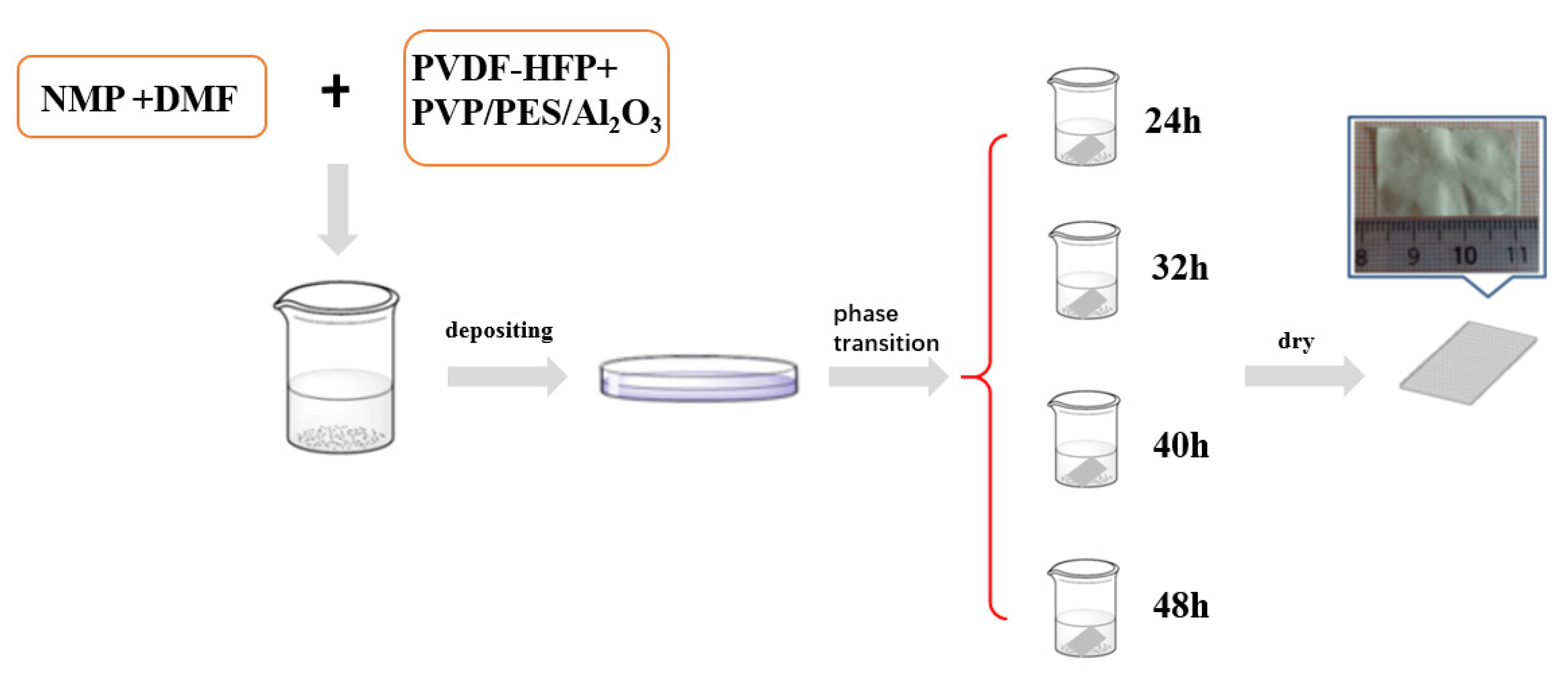
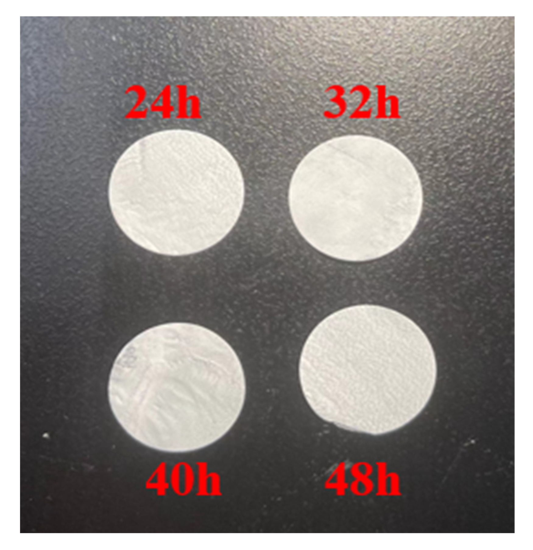
2.2. Preparation of Carrier Film and Polymer Electrolyte with Different Phase Transition Times

First, we prepared the carrier film according to the previous process. We dispersed PVDF-HFP, surface-modified alumina (wt15%), polyether sulfone, and polyvinylpyrrolidone (PVP) uniformly in a mixture of NMP and DMF. The specific preparation process is shown in Figure 1 [14,33,34].
The membrane was then removed and placed in a mixture of ethanol–water (1:1). The soaking solution was replaced every 8 h, and the phase conversion time was set as 24 h, 32 h, 40 h, and 48 h for the experimental group. The phase conversion membrane was dried and the impurities in it dissolved and precipitated to obtain a carrier film with good performance. Then, the phase conversion film was cut into 16 cm diameter slices to prepare the polymer electrolyte for the next step. Next, the carrier membrane adsorbed the precursor liquid, and the polymer electrolyte was prepared by the UV curing method. Thus, we further characterized the electrochemical properties of electrolytes and batteries [10].

2.3. Preparation Method of Polymer Electrolyte

In this experiment, we used the UV curing method to prepare polymer electrolytes. First, the carrier films with different phase conversion times previously prepared were cut to the size of a button cell diaphragm for use. Then, the precursor liquid of the electrolyte was prepared. The specific method is to mix a certain proportion of 1.2 g succindinitrile (SN) with 0.8 g LiTFSI. Because the two will promote each other to lower the melting point, it will melt into a liquid in a few minutes. Then, 0.05 g of plasticizer was added to the mixed solution and stirred well. After that, 0.2 g of the polymeric monomer ETPTA of this electrolyte was added to the mixed solution and mixed thoroughly for a few minutes until well blended. Finally, the electrolyte precursor was prepared by adding a small amount of photoinitiator, about 0.01 g. The carrier film with the best surface effect was then selected to fully absorb the electrolyte precursor. When the quality of the carrier film did not change, it was covered on the electrode plate in the battery shell and irradiated with high-intensity ultraviolet light. After a few minutes, in situ UV polymerization curing was completed [14,33,34]. This method has the advantage of simple operation, high efficiency, and no pollution.

2.4. Material Characterization Method

The scanning electron microscope (SEM; Hitachi S-4800, Hitachi Co., Ltd., Tokyo, Japan) was used for characterization. To improve the conductivity of the sample, the sample was treated with gold spray, and the secondary electron mode was used to observe the electrolyte section. The structure of the sample was analyzed by X-ray diffraction (XRD). The role of Nicolet 6700 Fourier Transform (Thermo Electron Corporation, Waltham, MA, USA) infrared spectroscopy (FT-IR) is to analyze the functional groups present in the polymer electrolyte. The thermal stability of the polymer electrolyte prepared in this paper was analyzed by thermogravimetric analysis with a thermal analyzer (Q2000, TGA/DSC3+, Mettler, Switzerland) [14,33,34].
We usually use the AC impedance method to measure the ionic conductivity of polymer electrolytes. Ionic conductivity is calculated as σ = L/(R·S). First, the electrochemical stability of polymer electrolytes is generally analyzed using cyclic voltammetry curves. The electrolyte was assembled into a lithium metal/polymer electrolyte/stainless steel asymmetric battery which was analyzed with a scan rate of 0.1 mV/s [14,33,34].

3. Results and Discussion

Figure 2 shows the optical images of carrier films prepared at different phase conversion times. It can be seen that the carrier film was grayish-white, almost opaque, and it had good flexibility. From a macro point of view, there was no significant difference in the surface state of the carrier film prepared at the four different phase transition times, all of which were uniform and flat membrane structures.
To further explore the effect of the phase transition time on the performance of the carrier membrane, the mechanical strength of the carrier membrane and the electrolyte prepared by the carrier membrane were tested. Figure 3a,b shows the mechanical property curves of the carrier membranes and electrolytes. It can be seen that the mechanical strength of the carrier film decreases gradually as the phase transition time increases. Interestingly, however, the mechanical strength of the electrolyte it forms is not monotonous. With the increase in the phase transition time from 24 h to 40 h, the mechanical strength of the electrolyte gradually increased. However, when the phase conversion time reached 48 h, the mechanical strength of the electrolyte began to decline to a value lower than that at 40 h. According to this phenomenon, we speculate that when the phase transition time is too long, it may affect the internal structure of the electrolyte and decrease the mechanical strength of the electrolyte. The most likely reason for this is that the phase transition time is too long so a large pore structure in the carrier membrane is formed. Because the pore structure is too sparse, it is difficult for the electrolyte to attach to the surface of the skeleton to form a uniform and stable structure.
The research on the interface between electrodes and electrolytes in solid-state batteries has always been a hot topic. Li et al. combined solid polymer electrolytes with defect-rich Ga2O3 nanobricks to prepare high-performance lithium metal batteries and the effect was also very good [35]. Seongsoo et al. studied the interface contact between solid metal lithium battery electrodes and solid electrolytes and achieved very good results [36]. To verify our hypothesis, the micromorphologies of the carrier films prepared with different phase transition times and the corresponding electrolytes were analyzed. Figure 4a–h shows the SEM images of the carrier membranes and electrolytes. It can be seen from Figure 4a–d that with the increase in the phase transition time, the porosity and pore structure of the surface of the carrier film gradually increase, so the mechanical strength gradually decreases. This is also a good explanation for the phenomenon in Figure 3a. As can be seen from Figure 4e–h, the electrolyte formed after ultraviolet curing presents a folded shape on the surface of the carrier film, which is caused by the volatilization of the plasticizer. As displayed in Figure 4e–g, the fold structure gradually became dense, which is caused by the gradual increase in the porosity on the surface of the carrier film. However, in Figure 4h, the fold structure on the electrolyte surface suddenly appears less, and significant roughness appears on the electrolyte surface. This is caused by the excessive macropore structure in the carrier membrane which makes the pore structure too sparse so that the electrolyte cannot be well attached to the skeleton surface. Therefore, the phenomenon in Figure 3b can also be well explained.
Thermogravimetric analysis was performed on the carrier films prepared at different phase transition times and their corresponding electrolytes to explore their thermal stability. As seen in Figure 5a, the carrier film has good thermal stability, and thermal decomposition did not occur until temperatures in excess of 350 °C. This excellent thermal stability can fully meet the requirements of the working conditions of polymer electrolytes. The thermal stability of the carrier film with different phase transition times was not different. The results showed that the phase transition time only changed the pore size and porosity of the carrier film but did not change the composition and chemical properties of the carrier film. As shown in Figure 5b, the polymer electrolyte began to lose about 40% of its weight at 200 °C, mainly due to the thermal decomposition of butyronitrile. The thermal stability of polymer electrolytes was significantly better at 205–375 °C when the butyronitrile was almost completely decomposed. The weight loss above 375 °C was mainly due to the thermal decomposition of LiTFSI and the carrier film. Such high thermal stability can fully meet the requirements of lithium-ion battery working conditions. The thermal stability of electrolytes prepared by carrier membranes with different phase transition times was not different [11,24].
At the same time, we also conducted an XRD analysis of the carrier films prepared at different phase conversion times and the corresponding electrolytes to explore the internal structure of the samples. Figure 6b shows that there was no significant difference in the lattice type of the electrolytes prepared by the carrier film with various phase transition times. However, it can be seen from Figure 6a that the absorption peak intensity increased with the increase in the phase transition time between 24 and 40 h. However, when the phase transition time reached 48 h, the absorption peak intensity decreased. On the surface of the 48 h sample, the internal structure of the carrier film changed suddenly, resulting in a decrease in the absorption peak strength. This phenomenon further confirmed our previous conjecture.
Next, we explored the electrochemical properties of the polymer electrolytes made from carrier films with different phase transition times. First, we tested the cycling performance of the LiFePO4/PCCE/Li battery at room temperature at 0.2 C. As seen from Figure 7a–d, the battery assembled by the polymer electrolyte with a phase conversion time of 40 h had the best cycle performance and the highest specific discharge capacity of 155.6 mAh/g after 70 cycles. On the 70th cycle, the discharge-specific capacity was 152.4 mAh/g with a capacity retention rate of 98% and discharge efficiency close to 100%. In contrast, in the other groups of batteries, the discharge capacity was reduced during the cycle. The specific discharge capacity of the sample with a phase conversion time of 48 h decreased the fastest, therefore, we concluded that the cycle performance is the best when the phase conversion time is 40 h.
We next explored the ionic conductivity and the rate performance of the polymer electrolytes made from the carrier films with different phase transition times. Figure 8a shows the ionic conductivity of the polymer electrolytes at different temperatures. It can be seen that the sample with a phase conversion time of 40 h had the highest ionic conductivity. The ionic conductivity was 1.02 × 10⁻³ S/cm at 25 °C and 3.42 × 10⁻³ S/cm at 60 °C. The ionic conductivity of the sample with a phase conversion time of 48 h decreased significantly. This phenomenon further confirms our previous conjecture. The same conclusion can be drawn in Figure 8b. The battery operated similarly at low current densities, however, under the high-rate discharge, the sample with a phase conversion time of 40 h had the highest discharge-specific capacity while the sample with a phase conversion time of 48 h had the worst discharge effect. Based on the above results, we chose the sample with a phase transition time of 40 h as the key research object in the future, i.e., the optimum phase conversion time of carrier film is 40 h.
High-temperature performance is also an important index to evaluate lithium-ion batteries. For this purpose, we assembled the best process sample into LiFePO4/S-PCCE/Li batteries and tested the high-temperature cycling performance at 55 °C. The results are shown in Figure 9. Figure 9a,b shows the charge-discharge cycle curves of the samples with a phase conversion time of 40 h at room temperature and high temperature. The sample still worked well at the high temperature of 55 °C, and the specific discharge capacity was still very high. This shows that the sample prepared by this process can meet the requirements of a lithium-ion battery working at high temperatures.
Finally, we studied the formation of the cathode-electrolyte-interface phase (CEI) membrane on the cathode surface of the battery composed of the optimal process samples and tested the TEM images of the LiFePO4 cathode under different charging states.
As shown in Figure 10a–c, a uniform CEI film with a thickness of about 8 nm is formed on the surface of the cathode when the cathode reaches the 100% charged state. When the battery power reaches 100%, the CEI film on the cathode surface is separated. This ensures that the polymer electrolyte is tightly bound to the cathode and the battery, and the battery is able to function normally and stably [14,33].

4. Conclusions

In conclusion, the phase conversion time of the carrier membrane has a great influence on the performance of polymer electrolytes. With the increase in the phase transition time, the pore structure and porosity of the carrier film increase. However, the excessive porosity of the skeleton structure makes it more difficult to attach the electrolyte, which leads to the deterioration in its performance. Through the analysis of carrier films prepared with multiple phase transition times, we saw that the sample with a phase transition time of 40 h had the best comprehensive performance. The ionic conductivity of the polymer electrolyte prepared with this sample was 1.02 × 10⁻³ S/cm at 25 °C. When the temperature reached 60 °C, it had an ionic conductivity of up to 3.42 × 10⁻³ S/cm. When assembled into a battery, it also had the best cycle performance, with the highest specific discharge capacity of 155.6 mAh/g. The carrier film also had good thermal stability; at the 70th cycle, the discharge-specific capacity was 152.4 mAh/g with a capacity retention rate of 98% and discharge efficiency close to 100%. Therefore, the 40 h phase conversion time will be selected as the optimal process in the follow-up study of this project. The method using in situ UV curing has the advantages of simple operation, energy saving, and high efficiency, and has a good practical application prospect.

Author Contributions

Regarding the contributions of the authors, they are as follows: investigation, H.Z.; writing—original draft preparation, S.Z.; writing—review and editing, L.Q.; supervision, L.Z.; project administration, X.L.; funding acquisition, Z.W. All authors have read and agreed to the published version of the manuscript.

Funding

National Natural Science Foundation of China (Grant No. 51902072 and 22075062), Heilongjiang Touyan Team (Grant No. HITTY-20190033), Heilongjiang Province “hundred million” project science and technology major special projects (2019ZX09A02), the State Key Laboratory of Urban Water Resource and Environment (Harbin Institute of Technology No. 2020DX11), and the Fundamental Research Funds for the Central Universities (Grant No. FRFCU5710051922).

Data Availability Statement

All data in this paper are original by the author.

Acknowledgments

We acknowledge the National Natural Science Foundation of China (Grant No. 51902072 and 22075062), Heilongjiang Touyan Team (Grant No. HITTY-20190033), Heilongjiang Province “hundred million” project science and technology major special projects (2019ZX09A02), the State Key Laboratory of Urban Water Resource and Environment (Harbin Institute of Technology No. 2020DX11), and the Fundamental Research Funds for the Central Universities (Grant No. FRFCU5710051922).

Conflicts of Interest

The authors declare no conflict of interest.

References

  1. Zhang, Z.; Antonio, R.G.; Choy, K.L. Boron nitride enhanced polymer/salt hybrid electrolytes for all-solid-state lithium ion batteries. J. Power Sources 2019, 435, 226736. [Google Scholar] [CrossRef]
  2. Zhang, Q.G.; Hu, W.W.; Liu, Q.L.; Zhu, A.M. Chitosan/polyvinylpyrrolidone-silica hybrid membranes for pervaporation separation of methanol/ethylene glycol azeotrope. J. Appl. Polym. Sci. 2013, 129, 3178–3184. [Google Scholar] [CrossRef]
  3. Liu, L.; Mo, J.; Li, J.; Liu, J.; Yan, H.; Lyu, J.; Jiang, B.; Chu, L.; Li, M. Comprehensively-modified polymer electrolyte membranes with multifunctional PMIA for highly-stable all-solid-state lithium-ion batteries. J. Energy Chem. 2020, 48, 334–343. [Google Scholar] [CrossRef]
  4. Pan, Q.; Barbash, D.; Smith, D.M.; Qi, H.; Gleeson, S.E.; Li, C.Y. Correlating Electrode-Electrolyte Interface and Battery Performance in Hybrid Solid Polymer Electrolyte-Based Lithium Metal Batteries. Adv. Energy Mater. 2017, 7, 1701231. [Google Scholar] [CrossRef]
  5. Kongthong, T.; Tuantranont, S.; Primpray, V.; Sriprachuabwong, C.; Poochai, C. Rechargeable lithium-ion dual carbon batteries utilising a quasi-solid-state anion co-intercalation electrolyte and palm kernel shell-derived hard carbon. Diam. Relat. Mater. 2023, 132, 109680. [Google Scholar] [CrossRef]
  6. Kim, S.-H.; Choi, K.-H.; Cho, S.-J.; Yoo, J.; Lee, S.-S.; Lee, S.-Y. Flexible/shape-versatile, bipolar all-solid-state lithium-ion batteries prepared by multistage printing. Energy Environ. Sci. 2018, 11, 321–330. [Google Scholar] [CrossRef]
  7. Zhou, D.; Liu, R.; He, Y.-B.; Li, F.; Liu, M.; Li, B.; Yang, Q.-H.; Cai, Q.; Kang, F. SiO2Hollow Nanosphere-Based Composite Solid Electrolyte for Lithium Metal Batteries to Suppress Lithium Dendrite Growth and Enhance Cycle Life. Adv. Energy Mater. 2016, 6, 1502214. [Google Scholar] [CrossRef]
  8. Zhao, Q.; Stalin, S.; Zhao, C.-Z.; Archer, L.A. Designing solid-state electrolytes for safe, energy-dense batteries. Nat. Rev. Mater. 2020, 5, 229–252. [Google Scholar] [CrossRef]
  9. Zhou, W.; Gao, H.; Goodenough, J.B. Low-Cost Hollow Mesoporous Polymer Spheres and All-Solid-State Lithium, Sodium Batteries. Adv. Energy Mater. 2016, 6, 1501802. [Google Scholar] [CrossRef]
  10. Ha, H.-J.; Kil, E.-H.; Kwon, Y.H.; Kim, J.Y.; Lee, C.K.; Lee, S.-Y. UV-curable semi-interpenetrating polymer network-integrated, highly bendable plastic crystal composite electrolytes for shape-conformable all-solid-state lithium ion batteries. Energy Environ. Sci. 2012, 5, 6491. [Google Scholar] [CrossRef]
  11. Wang, Q.J.; Zhang, P.; Zhu, W.Q.; Zhang, D.; Li, Z.J.; Wang, H.; Sun, H.; Wang, B.; Fan, L.-Z. A two-step strategy for constructing stable gel polymer electrolyte interfaces for long-life cycle lithium metal batteries. J. Mater. 2022, 8, 1048–1057. [Google Scholar] [CrossRef]
  12. Li, J.; Zhu, L.; Xu, J.; Jing, M.; Yao, S.; Shen, X.; Li, S.; Tu, F. Boosting the performance of poly (ethylene oxide)-based solid polymer electrolytes by blending with poly (vinylidene fluoride-co-hexafluoropropylene) for solid-state lithium-ion batteries. Int. J. Energy Res. 2020, 44, 7831–7840. [Google Scholar] [CrossRef]
  13. Sha, Y.; Yu, T.; Dong, T.; Wu, X.; Tao, H.; Zhang, H. In Situ Network Electrolyte Based on a Functional Polymerized Ionic Liquid with High Conductivity toward Lithium Metal Batteries. ACS Appl. Energy Mater. 2021, 4, 14755–14765. [Google Scholar] [CrossRef]
  14. Zhang, S.; Lu, Y.; He, K.; Meng, X.; Que, L.; Wang, Z. Effect of UV light polymerization time on the properties of plastic crystal composite polyacrylate polymer electrolyte for all solid-state lithium-ion batteries. J. Appl. Polym. Sci. 2022, 139, e52001. [Google Scholar] [CrossRef]
  15. Doyle, E.S.; Ford, H.O.; Webster, D.N.; Giannini, P.J.; Tighe, M.E.; Bartsch, R.; Peaslee, G.F.; Schaefer, J.L. Influence of Inorganic Glass Ceramic Particles on Ion States and Ion Transport in Composite Single-Ion Conducting Gel Polymer Electrolytes with Varying Chain Chemistry. ACS Appl. Polym. Sci. 2022, 4, 1095–1109. [Google Scholar] [CrossRef]
  16. Deng, L.; Yu, F.-D.; Xia, Y.; Jiang, Y.-S.; Sui, X.-L.; Zhao, L.; Meng, X.-H.; Que, L.-F.; Wang, Z.-B. Stabilizing fluorine to achieve high-voltage and ultra-stable Na3V2(PO4)(2)F-3 cathode for sodium ion batteries. Nano Energy 2021, 82, 105659. [Google Scholar] [CrossRef]
  17. Wang, D.L.; Li, K.; Teo, W.K. Porous PVDF asymmetric hollow fiber membranes prepared with the use of small molecular additives. J. Membr. Sci. 2000, 178, 13–23. [Google Scholar] [CrossRef]
  18. Jeon, H.G.; Ito, Y.; Sunohara, Y.; Ichikawa, M. Dependence of photocurrent generation on the crystalline phase of titanyl phthalocyanine film in heterojunction photovoltaic cells. Jpn. J. Appl. Phys. 2015, 54, 091601. [Google Scholar] [CrossRef]
  19. Mansourizadeh, A.; Ismail, A.F. A developed asymmetric PVDF hollow fiber membrane structure for CO2 absorption. Int. J. Greenh. Gas Control 2011, 5, 374–380. [Google Scholar] [CrossRef]
  20. Xu, H.; Zhang, X.; Jiang, J.; Li, M.; Shen, Y. Ultrathin Li7La3Zr2O12@PAN composite polymer electrolyte with high conductivity for all-solid-state lithium-ion battery. Solid State Ion. 2020, 347, 115227. [Google Scholar] [CrossRef]
  21. Wang, L.Y.; Yong, W.F.; Yu, L.E.; Chung, T.S. Design of high efficiency PVDF-PEG hollow fibers for air filtration of ultrafine particles. J. Membr. Sci. 2017, 535, 342–349. [Google Scholar] [CrossRef]
  22. Liu, S.J.; Liu, M.H.; Xu, Q.; Zeng, G.F. Lithium Ion Conduction in Covalent Organic Frameworks. Chin. J. Struct. Chem. 2022, 41, 2211003-17. [Google Scholar]
  23. Li, S.; Zhang, S.Q.; Shen, L.; Liu, Q.; Ma, J.B.; Lv, W.; He, Y.; Yang, Q. Progress and Perspective of Ceramic/Polymer Composite Solid Electrolytes for Lithium Batteries. Adv. Sci. 2020, 7, 1903088. [Google Scholar] [CrossRef]
  24. Chen, Y.; Tian, Y.; Li, Z.; Zhang, N.; Zeng, D.; Xu, G.; Zhang, Y.; Sun, Y.; Ke, H.; Cheng, H. An AB alternating diblock single ion conducting polymer electrolyte membrane for all-solid-state lithium metal secondary batteries. J. Membr. Sci. 2018, 566, 181–189. [Google Scholar] [CrossRef]
  25. Lu, Q.; Yang, J.; Lu, W.; Wang, J.; Nuli, Y. Advanced semi-interpenetrating polymer network gel electrolyte for rechargeable lithium batteries. Electrochim. Acta 2015, 152, 489–495. [Google Scholar] [CrossRef]
  26. Yang, M.X.; Zhao, B.Q.; Li, J.Y.; Li, S.M.; Zhang, G.; Liu, S.Q.; Cui, Y.; Liu, H. Modified Poly(vinylidene fluoride-co-hexafluoropropylene) Polymer Electrolyte for Enhanced Stability and Polymer Degradation Inhibition toward the Li Metal Anode. ACS Appl. Energy Mater. 2022, 5, 9049–9057. [Google Scholar] [CrossRef]
  27. Yao, W.; Zhang, Q.; Qi, F.; Zhang, J.; Liu, K.; Li, J.; Chen, W.; Du, Y.; Jin, Y.; Liang, Y.; et al. Epoxy containing solid polymer electrolyte for lithium ion battery. Electrochim. Acta 2019, 318, 302–313. [Google Scholar] [CrossRef]
  28. Tao, C.; Gao, M.-H.; Yin, B.-H.; Li, B.; Huang, Y.-P.; Xu, G.; Bao, J.-J. A promising TPU/PEO blend polymer electrolyte for all-solid-state lithium ion batteries. Electrochim. Acta 2017, 257, 31–39. [Google Scholar] [CrossRef]
  29. Kumar, A.; Sharma, R.; Suresh, M.; Das, M.K.; Kar, K.K. Structural and ion transport properties of lithium triflate/poly (vinylidene fluoride-co-hexafluoropropylene)-based polymer electrolytes: Effect of lithium salt concentration. J. Elastom. Plast. 2017, 49, 513–526. [Google Scholar] [CrossRef]
  30. Zhou, D.; He, Y.-B.; Liu, R.; Liu, M.; Du, H.; Li, B.; Cai, Q.; Yang, Q.-H.; Kang, F. In Situ Synthesis of a Hierarchical All-Solid-State Electrolyte Based on Nitrile Materials for High-Performance Lithium-Ion Batteries. Adv. Energy Mater. 2015, 5, 1500353. [Google Scholar] [CrossRef]
  31. Lv, P.; Yang, J.; Liu, G.; Liu, H.; Li, S.; Tang, C.; Mei, J.; Li, Y.; Hui, D. Flexible solid electrolyte based on UV cured polyurethane acrylate/succinonitrile-lithium salt composite compatibilized by tetrahydrofuran. Compos. Part B Eng. 2017, 120, 35–41. [Google Scholar] [CrossRef]
  32. Wang, Y.; Fang, C.; Liu, W.; Pei, H.; Zhan, B.; Zou, W.; Yu, S.; Guo, R.; Xie, J. Constructing Self-Protected Li and Non-Li Candidates for Advanced Lithium Ion and Lithium Metal Batteries. J. Phys. Chem. C 2019, 123, 13318–13323. [Google Scholar] [CrossRef]
  33. Zhang, S.J.; Lu, Y.; He, K.W.; Que, L.F.; Zhao, L.; Wang, Z.B. The plastic crystal composite polyacrylate polymer electrolyte with a semi-interpenetrating network structure for all-solid-state LIBs. New J. Chem. 2022, 46, 21640–21647. [Google Scholar] [CrossRef]
  34. Lu, Y.; He, K.-W.; Zhang, S.-J.; Zhou, Y.-X.; Wang, Z.-B. UV-curable-based plastic crystal polymer electrolyte for high-performance all-solid-state Li-ion batteries. Ionics 2018, 25, 1607–1615. [Google Scholar] [CrossRef]
  35. Li, H.; Xu, X.; Li, F.; Zhao, J.; Ji, S.; Liu, J.; Huo, Y. Defects-Abundant Ga2O3 Nanobricks Enabled Multifunctional Solid Polymer Electrolyte for Superior Lithium-Metal Batteries. Chem. Eur. J. 2023, 29, e202204035. [Google Scholar] [CrossRef]
  36. Seongsoo, P.; Rashama, C.; Sang, A.H.; Hamzen, Q.; Moon, J.; Park, M.-S.; Kim, J.H. Ionic conductivity and mechanical properties of the solid electrolyte interphase in lithium metal batteries. Energy Mater. 2023, 3, 300005. [Google Scholar]
Figure 1. Flow chart of carrier film preparation with different phase transition times.
Batteries 09 00471 g001
Figure 2. The optical images of the carrier films prepared with different phase transition times.
Batteries 09 00471 g002
Figure 3. Mechanical properties of the carrier membrane and polymer electrolyte: (a) the carrier membrane and (b) the polymer electrolyte.
Batteries 09 00471 g003
Figure 4. SEM images of the carrier membranes prepared at (a) 24 h, (b) 32 h, (c) 40 h, and (d) 48 h; SEM images of polymer electrolytes based on the carrier membranes prepared at (e) 24 h, (f) 32 h, (g) 40 h, and (h) 48 h.
Batteries 09 00471 g004
Figure 5. The TG curves of (a) the carrier membrane and (b) the polymer electrolyte.
Batteries 09 00471 g005
Figure 6. The XRD patterns of (a) the carrier membranes and (b) the polymer electrolytes.
Batteries 09 00471 g006
Figure 7. Cycle performance of the batteries composed of electrolytes with different phase transition durations: (a) 24 h, (b) 32 h, (c) 40 h, and (d) 48 h.
Batteries 09 00471 g007
Figure 8. (a) Ionic conductivity of electrolytes with different phase transition times. (b) The rate performance of the batteries composed of electrolytes with different phase transition times.
Batteries 09 00471 g008
Figure 9. High-temperature performance of batteries with the optimum process electrolytes at (a) 25 °C and (b) 55 °C.
Batteries 09 00471 g009
Figure 10. TEM images of the (a) LiFePO4 cathode at the pristine state, (b) LiFePO4 cathode with a charge state of 100%, and (c) LiFePO4 cathode with a discharge state of 100%.
Batteries 09 00471 g010
Disclaimer/Publisher’s Note: The statements, opinions and data contained in all publications are solely those of the individual author(s) and contributor(s) and not of MDPI and/or the editor(s). MDPI and/or the editor(s) disclaim responsibility for any injury to people or property resulting from any ideas, methods, instructions or products referred to in the content.

