Article

Molybdenum Nitride and Oxide Quantum Dot @ Nitrogen-Doped Graphene Nanocomposite Material for Rechargeable Lithium Ion Batteries

1
School of Material and Chemical Engineering, Zhengzhou University of Light Industry, Zhengzhou 450001, China
2
Ceramic Materials Research Center, Zhengzhou University of Light Industry, Zhengzhou 450001, China
*
Authors to whom correspondence should be addressed.
Batteries 2023, 9(1), 32; https://doi.org/10.3390/batteries9010032
Submission received: 13 October 2022 / Revised: 4 December 2022 / Accepted: 8 December 2022 / Published: 31 December 2022
(This article belongs to the Special Issue Electrode Materials for Rechargeable Lithium Batteries)

Abstract

:
A multistage architecture with molybdenum nitride and oxide quantum dots (MON-QDs) uniformly grown on nitrogen-doped graphene (MON-QD/NG) is prepared by a facile and green hydrothermal route followed by a one-step calcination process for lithium ion batteries (LIBs). Characterization tests show that the MON-QDs with diameters of 1–3 nm are homogeneously anchored on or intercalated between graphene sheets. The molybdenum nitride exists in the form of crystalline Mo2N (face-centered cubic), while molybdenum oxide exists in the form of amorphous MoO2 in the obtained composite. Electrochemical tests show that the MON-QD/NG calcinated at 600 °C has an excellent lithium storage performance with an initial discharge capacity of about 1753.3 mAh g−1 and a stable reversible capacity of 958.9 mAh g−1 at current density of 0.1 A g−1 as well as long-term cycling stability at high current density of 5 A g−1. This is due to the multistage architecture, which can provide plenty of active sites, buffer volume changes of electrode and enhance electrical conductivity as well as the synergistic effect between Mo2N and MoO2.

1. Introduction

Transition metal nitrides (MNx, M = Mo, Fe, Ni, V, W, etc.) are useful materials with numerous industrial applications, such as abrasives, cutting tools, electronics, catalysis as well as electrochemical applications. Due to the excellent metallic conductivity and low polarization loss, transition metal nitrides have been used widely as energy storage materials, e.g., LIB anode materials, in recent years. The molybdenum nitrides are promising anode materials in LIBs among the various transition metal nitrides [1,2,3,4]. For the sake of overcoming the limitations of large volume change during the charge/discharge progress, low diffusion rate of electrolyte and lithium ion as well as poor electron transport at high rate of cycles, the molybdenum nitrides were prepared into all kinds of nano-shaped particles or/and combined with other materials forming composites [3,5,6,7,8,9,10,11,12,13,14,15,16,17]. Zheng et al. [18] prepared a nano-complex with Mo2N quantum dots @MoO3@nitrogen-doped carbon (MON-NC) by a sol–gel method. Electrochemical performance tests showed that MON-NC has much higher rate performance and longer life cycle performance than that of Mo2N@MoO3 and nitrogen doped carbon (NC). Liu et al. [19] prepared a composite with the Mo2N-coated hollow nanostructure of MoO2. The composite has a reversible capacity of 815 mAh g−1 after 100 cycles at current density of 0.1 A g−1. Zhang et al. [11] obtained a molybdenum nitride-doped graphene (MoN/GNS) composite material by calcining the precursor in NH3 atmosphere. The MoN/GNS composite had good rate and cycle performance. However, these preparation methods usually contain complicated procedures and harsh synthetic conditions such as the use of templates and toxic or dangerous gases (e.g., NH3 or H2), which are adverse to its practical application and large-scale production. Calcinating the complex AM-HMTA precursors of ammonium molybdate ((NH4)4Mo7O24•4H2O, AM) and hexamethylenetetramine (C6H12N4, HMTA) under N2/H2 mixed atmosphere is a relatively simple method to prepare molybdenum nitride [20,21]. In our previous research, we found that the Mo2N products contained part of MoO2 by calcinating the AM-HMTA precursors in pure N2 atmosphere [22]. The oxide MoO2 is also an intensely appealing anode material for LIBs owing to its higher theoretical specific capacity (838 mAh g−1) and higher density (6.5 g cm−3) than those of the currently used graphite anode.
Herein, we prepared molybdenum nitride and oxide quantum dots (MON-QDs) anchored on nitrogen-doped graphene (MON-QD/NG) composite material by a facile and green hydrothermal route followed by a one-step calcination process in pure N2 atmosphere. In the synthesis, graphene oxide (GO) can be added as an “assembled binder” to anchor these generated MON-QDs on reduced graphene oxide uniformly. The MON-QD/NG showed excellent lithium storage performance owing to the synergistic effect between 0D MON-QDs and 2D nitrogen-doped graphene nanosheets. MON-QDs can improve the electrochemical activity of electrode material by providing plenty of active sites while graphene nanosheets can inhibit the structure collapse and shorten the lithium ion diffusion pathway. Consequently, these superior characteristics endow MON-QD/NG with high lithium storage capacity, good cycle stability as well as excellent rate performance, and it is a promising anode material for LIBs.

2. Experimental Details

2.1. Preparation of Samples

Firstly, the precursors AM-HMTA and graphene oxide (GO) were prepared. The AM-HMTA was obtained by the following steps: (1) 3.5 g ammonium molybdate ((NH4)4Mo7O244H2O, AM) and 6 g hexamethylenetetramine (C6H12N4, HMTA) were dissolved in 50 mL deionized water, respectively; (2) the aqueous HMTA solution was added into the AM solution; (3) after magnetic stirring for 4 h, the mixed solution was left overnight to precipitate the white complex completely; (4) the AM-HMTA precursor was gained by filtering and then drying the white complex. The GO solution was prepared using graphite powder based on the method of modified Hummers [23]. Then, the prepared AM-HMTA was added to GO solution (4 mg mL−1) with a weight ratio of 7:3 followed by stirring for 12 h to form a stable AM-HMTA/GO solution. After the above processes, the AM-HMTA/GO solution was sealed in an autoclave and heated at 180 °C for 6 h to obtain nitrogen-doped sponge, which was freeze-dried for 72 h further. Lastly, the freeze-dried sponge was calcinated at 500 °C, 600 °C and 700 °C for 2 h under N2 atmosphere, respectively. The obtained samples were abbreviated as MON-QD/NG-500, MON-QD/NG-600 and MON-QD/NG-700 according to their calcinating temperature. Reduced graphene oxide (rGO) was also obtained via calcinating freeze-dried GO under the same conditions as that of MON-QD/NG.

2.2. Characterization

X-ray diffraction (XRD) tests were performed through a Rigaku Ultima IV instrument with Cu Kα radiation. A HORIBA Scientific LabRAM HR Evolution Raman spectrometer system was used to record the Raman spectra. X-ray photoelectron spectra (XPS) were recorded on a Perkin-Elmer PHI ESCA system. The microstructure and morphology of samples were observed by scanning electron microscope (SEM) (JSM-7001F) and transmission electron microscope (TEM) (JSM-2100). The specific surface area was measured by the Barrett–Emmett–Teller (BET) method. The pore size distribution was calculated by the Barrett–Joyner–Halenda (BJH) model.

2.3. Electrochemical Measurement

Electrochemical performances of the samples were measured through CR2016 coin type cells. The fabricated electrodes were prepared by mixing MON-QD/NG, polyvinylidene fluoride (PVDF) and carbon black in a weight ratio of 8:1:1 using N-methyl-2-pyrrolidone (NMP) as solvent. Then, the homogeneous slurry was coated onto a copper foil. Celgard 2400 polypropylene and pure lithium metal sheets were used as separator and counter electrode, respectively. The cells were assembled in an argon-filled glove box with concentration of H2O and O2 below 0.5 ppm. The assembled cells were allowed to stand for 24 h before electrochemical testing. Galvanostatic charge/discharge measurements were carried out in the voltage range between 0.01 and 3.00 V (vs. Li/Li+) on a battery test instrument (LANHE CT2001A, Wuhan, China). Rate performance was tested at current density from 0.1 to 5 A g−1. After rate performance tests, the samples directly underwent charge–discharge cycles 300 times at 5 A g−1. Cyclic voltammetry (CV) tests were performed in the voltage range of 0.01–3.00 V on an electrochemical workstation (CHI660E) at different scan rates from 0.1 to 1 mV s−1. Electrochemical impedance spectroscopy (EIS) was used in the frequency range of Hz to 0.01 Hz. The EIS spectra were fitted by Zview software.

3. Results and Discussion

3.1. Structural and Characterization

The crystal structures of the MON-QD/NG samples were confirmed by XRD patterns, as shown in Figure 1 The XRD pattern of rGO shows a broad diffraction peak at about 24° corresponding to the (002) diffraction plane of graphite, which may be related to the semi-graphitized nature [24,25]. Similarly, XRD patterns of MON-QD/NG samples show obvious diffraction characteristic peaks of graphene, corresponding to the rGO. Only weak diffraction peaks at 37.3°, 43.6°, 63.2° and 75.5° corresponding to the (111), (200), (220) and (311) crystal planes of the face-centered cubic (fcc) Mo2N (JCPDS:25-1366) can be observed. The weak and broadened characteristic peaks of fcc Mo2N may be related to the different micromorphology, such as crystal size. However, no diffraction peaks of MoO2 can be detected, due to the amorphous state.
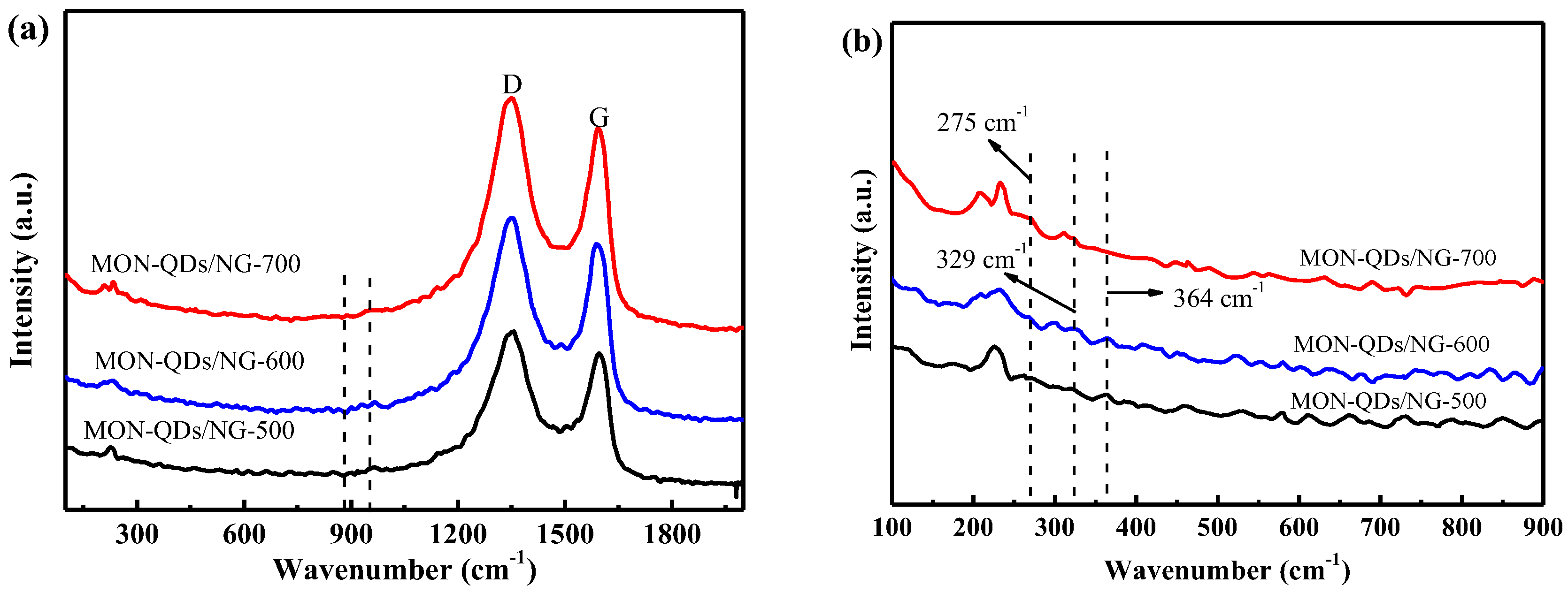
Raman tests were conducted on MON-QD/NG to further explore the structural information of the composites prepared at different temperatures, as shown in Figure 2. There are two strong peaks at about 1350 cm−1 and 1595 cm−1 of the three composites, which belong to D peak (associated with the sp3 defective) and G peak (arises from the bond stretching of all sp2−bonded pairs), respectively. In general, peak D represents the disordered induction peak of sp3 carbon, while peak G represents the stretching vibration of the C−C bond, which is related to the defect or small crystal size of graphene and the graphite lattice pattern and sp2 bond, respectively. The strength ratio of ID/IG was used to characterize the structural disorder degree, defect degree and graphitization properties of carbon materials [26]. Figure 2a shows the two characteristic peaks D, and G of graphene, and the intensity of peak D is significantly higher than that of peak G. Meanwhile, the asymmetric trailing extension of peak D extends to about 970 cm−1, which is caused by the nitrogen-doped graphene [27]. The strength ratios (ID/IG) of MON-QD/NG-500, MON-QD/NG-600 and MON-QD/NG-700 are 1.08, 1.09 and 1.12, respectively, indicating the higher graphitization degree of MON-QD/NG with the increase in temperature. Meanwhile, there are many topological edge defects in the three composites, and these defects may come from the small size of graphite fragments and residual functional groups. A large number of studies have pointed out that atom replacement defects in and outside the graphene surface formed by nitrogen and boron atoms can improve the electrical conductivity of graphene, which is more beneficial to the lithium storage performance of the materials. In addition, from the lower Raman shift spectra (Figure 2b), it is observed that the scattering peaks at 275, 329 and 364 cm−1 in the three composites are related to the phonon vibration modes of MoO2, suggesting the existence of MoO2 in the composites [28].
The chemical composition and electronic state of the prepared MON-QD/NG were investigated by XPS. The full spectrum of MON-QD/NG-600 is shown in Figure 3a. The sample mainly contains Mo, N, C and O elements. It can be seen from the full spectrum that the sample contains more O elements, which is caused by the existence of MoO2 and oxidation of the surface of the sample. Figure 3b is the peak fitting result of O element, which can be fitted into three peaks: peak Ⅰ at 529.9 eV is characteristic of the Mo-O bond, while peaks Ⅱ at 531.2 eV and Ⅲ at 532.8 eV are characteristic of the C-O-C bond and C=O bond, respectively, suggesting strong chemical interaction between MoO2 and graphene. In the N1s spectrum (Figure 3c), peak Ⅱ at 397.5 eV is the characteristic peak of the Mo-N bond, indicating the formation of Mo2N. Peaks Ⅲ, Ⅳ and Ⅴ at 398.2 eV, 399.7 eV and 401.6 eV correspond to pyridine nitrogen, pyrrole nitrogen and graphene nitrogen, respectively, indicating that nitrogen-doped graphene has been successfully prepared. In Figure 3d, there are four characteristic peaks in the C1s spectrum, which are respectively attributed to carbon in different chemical states: peak Ⅰ at 284.6 eV is the characteristic peak of the C-C bond, peak Ⅱ at 285.5 eV and peak Ⅳ at 289.3 eV are the characteristic peaks of the C-O bond and O=C-O bond, respectively, and peak Ⅲ at 287.3 eV is the characteristic peak of the C-N bond. These characteristic peaks indicate that MoO2 and Mo2N have strong chemical interactions with graphene, which is beneficial to charge transfer during charge and discharge. Figure 3e–g are the test results of Mo elements of MON-QD/NG-500, MON-QD/NG-600 and MON-QD/NG-700, respectively. The Mo3d spectra of the three composites can be divided into six peaks: peak Ⅰ located at about 229.8 eV and peak Ⅱ located at 232.0 eV can be identified as the presence of Mo4+, which corresponds to MoO2 phase. Peaks Ⅱ and Ⅳ at 231.7 eV and 232.7 eV are characteristic peaks of the Mo-N bond in the samples, indicating the further formation of Mo2N in the composites; peaks Ⅴ and Ⅵ at 233.4 eV and 235.2 eV are characteristic peaks of Mo6+, corresponding to the formation of MoO3 phase, which is caused by the oxidation of oxygen in the air. In addition, it is found from the Mo3d spectra of three composite materials that the content of Mo2N in the sample increases first and then decreases, while the content of MoO2 increases all the time with the increase in calcination temperature. It can also be found that the content of Mo2N in MON-QD/NG-700 composite is the lowest, while the content of MoO2 is the highest among the three kinds of composites. This is because Mo element itself is easily combined with O element. Furthermore, the activity of O atoms increases with the increase in calcination temperature. However, the poor conductivity of MoO2 restricts the cyclic and rate capability of the materials, which greatly affect the lithium storage properties of MON-QD/NG-700.
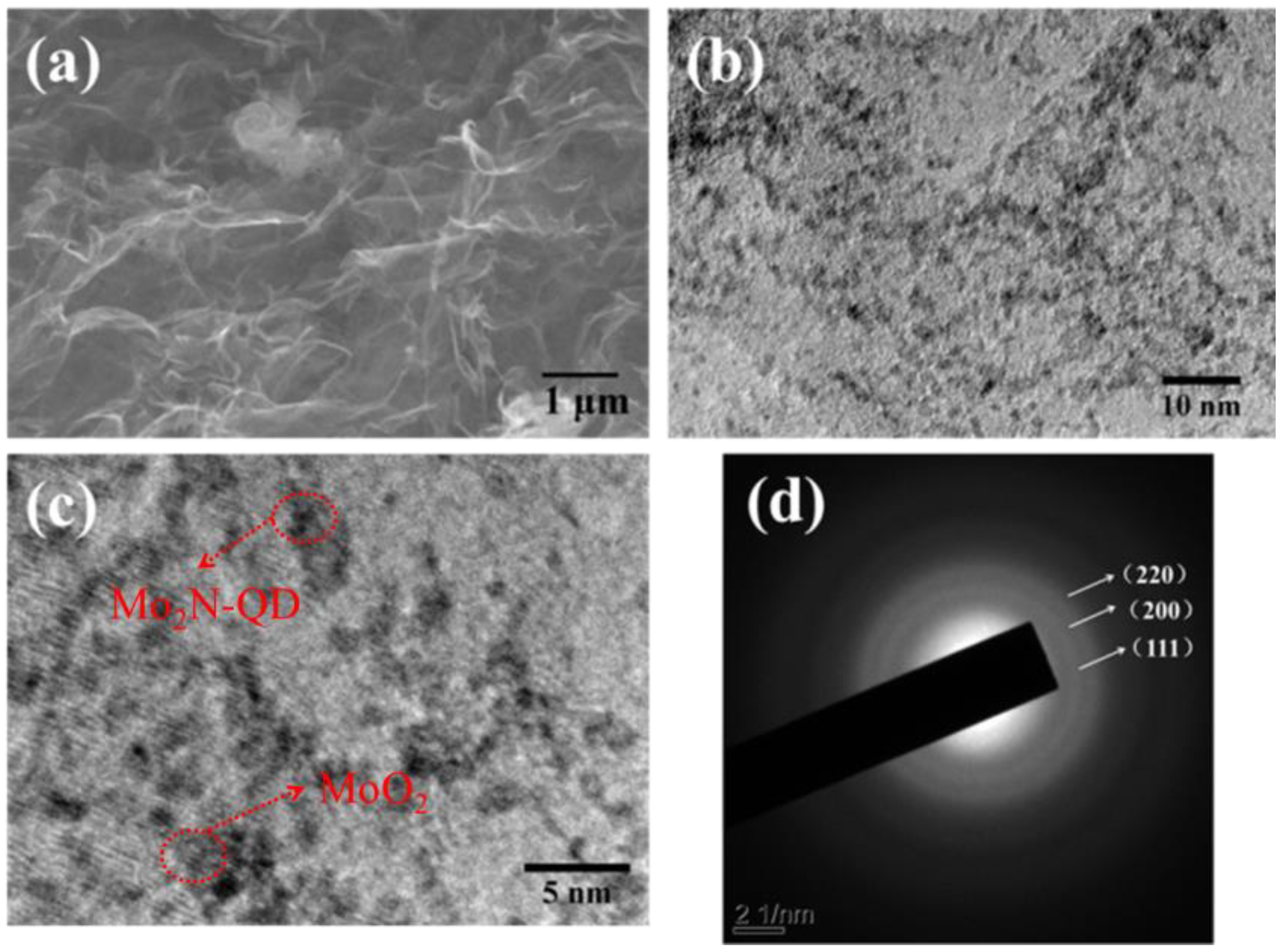
The morphology of MON-QD/NG-600 composite was observed by SEM and TEM, as shown in Figure 4a–d. Only the typical folded lamellar morphology of graphene can be observed in the SEM image (Figure 4a). However, from the TEM (Figure 4b) and HRTEM (Figure 4c) images, it can be found that a large number of small quantum dots with size of 1–3 nm evenly distribute on the graphene lamellae. Further observation from Figure 4c revealed that Mo2N quantum dots are evenly distributed in MoO2. The diffraction rings in the SAED image (Figure 4d) are correspond to the (111), (200) and (220) crystal planes of Mo2N, indicating the existence of Mo2N quantum dots in the composite material. However, the diffraction rings of MoO2 are not found in the SAED image, which indicates that MoO2 quantum dots exist in an amorphous state. The morphology of quantum dots can alleviate the volume change in electrode materials in the charging and discharging process, and GO also plays the role of template in the preparation process, resulting in a great change in the morphology of composite materials.
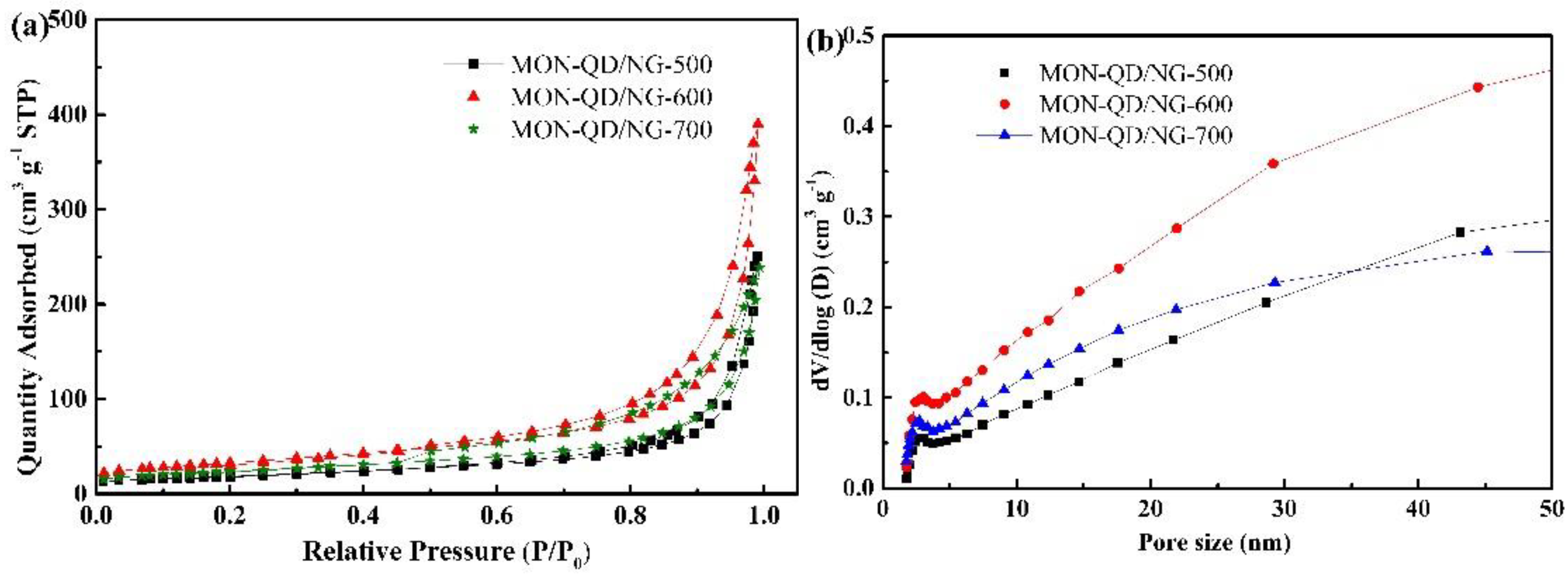
Figure 5a,b are the adsorption and desorption isothermal curves and pore size distribution of the three MON-QD/NG samples, respectively. There are obvious hysteresis loops in the three MON-QD/NG composites with a pressure ratio of about 0.8–1.0 (Figure 5a), indicating the existence of mesoporous structures in the composites. It can also be observed from Figure 5b that a large number of mesopores with pore sizes of about 2–50 nm exist in the three composites. The specific surface area of MON-QD/NG-600 is 116.9 m2 g−1 and pore volume is 0.60 cm3 g−1, which is larger than those of MON-QD/NG-500 (105 m2 g−1, 0.53 cm3 g−1) and MON-QD/NG-700 (100 m2 g−1, 0.48 cm3 g−1). The large specific surface area provides a fast channel for the migration of Li+ ions and the diffusion of electrolyte, which is conductive to the rapid insertion and extraction of electrolyte ions, thereby greatly improving electrochemical performance, particularly rate performance [8,29]. Meanwhile, high pore volume can provide buffer for material volume change during the charging and discharging process, thus improving energy density.

3.2. Electrochemical Characterization

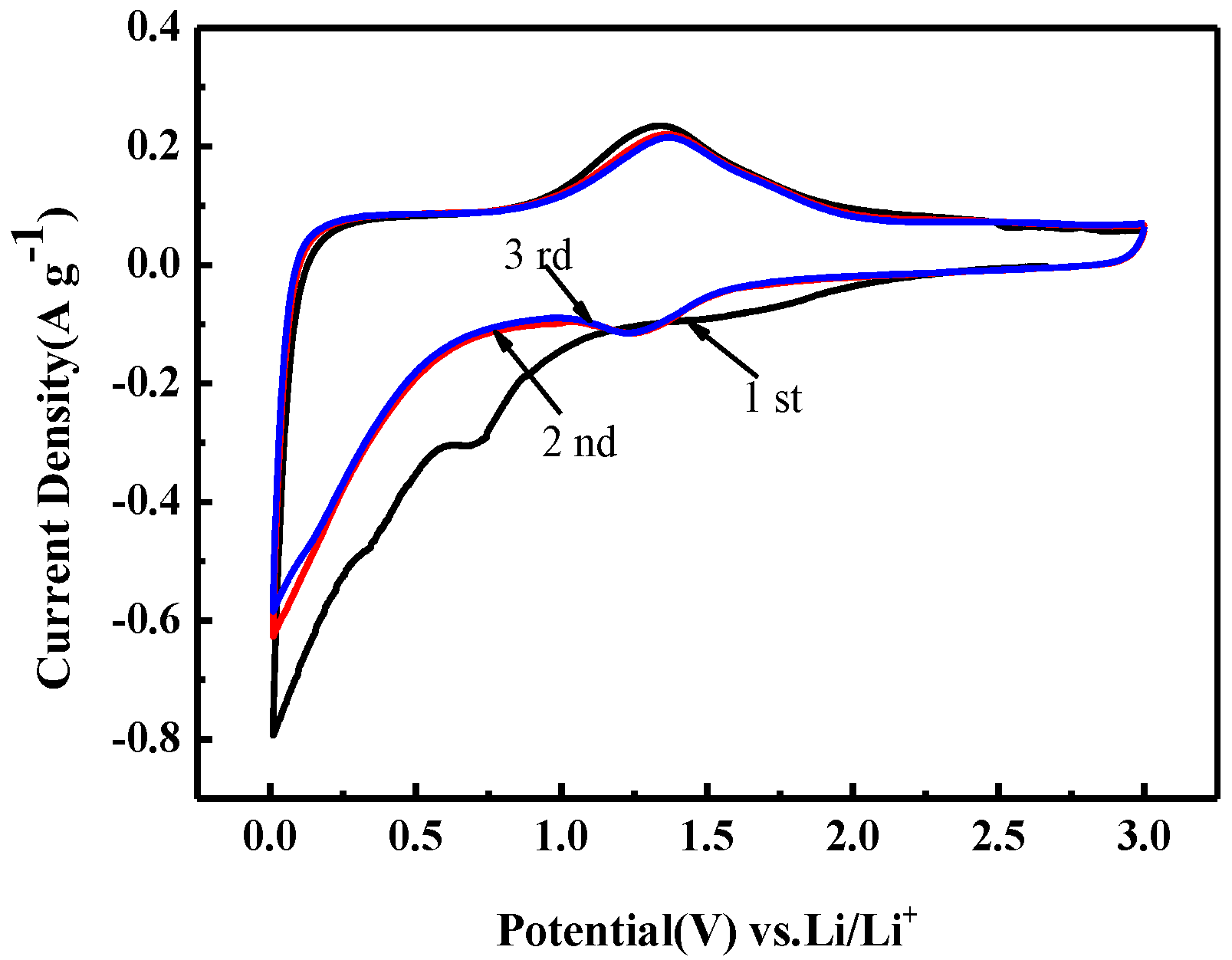
The cyclic voltammetry curve of MON-QD/NG-600 at 0.1 mV s−1 in the 0.01–3.0 V voltage range is shown in Figure 6. During the initial lithium process, the diffusion peak from about 1.65 V to 1.0 V may be Li+ inserted into the amorphous MoO2, accompanied by the formation of LixMoO2. However, during the first cathodic process, the peak of Li+ insertion into the MoO2 lattice (usually above 2.2 V) is not visible, which may be related to the amorphous nature of MoO2 [18,30]. When the electrode discharge voltage is lower than 1 V, the original LixMoO2 reacts with Li+ and gradually transforms into Mo and Li2O [30]. In addition, a significant reduction peak was observed at about 0.7 V in the first CV curve, which disappeared in the subsequent CV test, probably due to the formation of the solid electrolyte interface layer (SEI) [31]. Subsequently, two oxidation peaks at 1.41 V and 1.70 V are related to the transformation process of LixMoO2 and Mo to MoO2. The CV curves of the second and third cycles almost coincide, indicating that the electrode material has high reversibility.
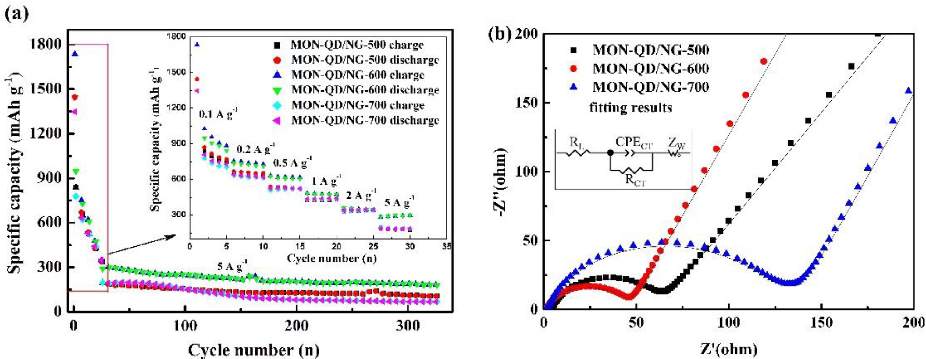
Charge and discharge curves at 0.1 A g−1 of MON-QD/NG-500, MON-QD/NG-600 and MON-QD/NG-700 are shown in Figure 7a, Figure 7b and Figure 7c, respectively. It is observed from the figures that the charge–discharge curves of the three composite materials all have obvious charge–discharge platforms. This is consistent with the redox peak in the CV curve. Additionally, the initial discharge-specific capacities of the three composites are 1445.6, 1753.3 and 1347.6 mAh g−1, respectively, while the initial charging capacities are 837, 957.7 and 777.3 mAh g−1, respectively. It is observed that MON-QD/NG-500 and MON-QD/NG-700 composites decay rapidly in subsequent cycles, while MON-QD/NG-600 composites exhibit excellent lithium storage performance. In order to explore the electrochemical lithium storage performance of the three electrode materials, the charge and discharge rate performance at current density from 0.1 to 5 A g−1 and the subsequent cycling property at 5 A g−1 of MON-QD/NG-500, MON-QD/NG-600 and MON-QD/NG-700 were tested, as shown in Figure 8a. In addition, charge–discharge curves at different current densities of the three materials are provided in the SI (Figure S1a–c). Obviously, MON-QD/NG-600 displays the best rate capability which has reversible capacity of 958.9, 727.4, 610.5, 476.0, 350.5, 297.2 mAh g−1 at the current density of 0.1, 0.2, 0.5, 1, 2, 5 A g−1, respectively. Furthermore, the reversible capacity of MON-QD/NG-600 is superior to the MoN/GNS (see Table S1 in the SI) [11], Mo2N nanolayer coated MoO2 hollow nanostructure [19], MON-NC [18], etc.
Subsequently, the three composites were cycled 300 times at a current density of 5 A g−1. Some selected charge–discharge curves (the first, 100, 200 and 300 cycles) during cycling tests at 5 A g−1 of MON-QD/NG-600 are also provided in the SI (as shown in Figure S2). The test results show that MON-QD/NG-600 still has a reversible capacity of about 180.1 mAh g−1 after about 300 cycles. However, MON-QD/NG-500 and MON-QD/NG-700 have a reversible capacity of 105.5 and 68.1 mAh g−1 after 300 cycles, respectively. It is quite evident that the cycling performance of MON-QD/NG-600 is obviously superior to that of MON-QD/NG-500 and MON-QD/NG-700.
The electrochemical kinetics of the three composites were analyzed by EIS spectra (as shown in Figure 8b). Each of them possesses one depressed semicircle in the high-frequency region and an inclined line in the low-frequency region, which relate to the charge transfer resistance and Li+ diffusion process, respectively [32,33,34]. Therefore, an equivalent circuit, as shown in the illustration in Figure 8b, was selected for fitting the impedance spectra, where RL, RCT, CPECT and ZW represent the electrolyte resistance, charge transfer resistance, double layer capacitance and Warburg impedance, respectively [35,36]. It is clearly shown that the fitted data are basically consistent with the test data. The calculated charge transfer resistances of MON-QD/NG-500, MON-QD/NG-600 and MON-QD/NG-700 are 45 Ω, 28 Ω and 78 Ω, respectively. Furthermore, the MON-QD/NG-600 electrode has a larger slope straight line, suggesting a faster Li+ diffusion process. Although the graphitization degree of graphene increases and the conductivity is enhanced with the increase in temperature, the content of MoO2 increases, which is not conducive to the lithium storage performance of electrode materials under high current density.
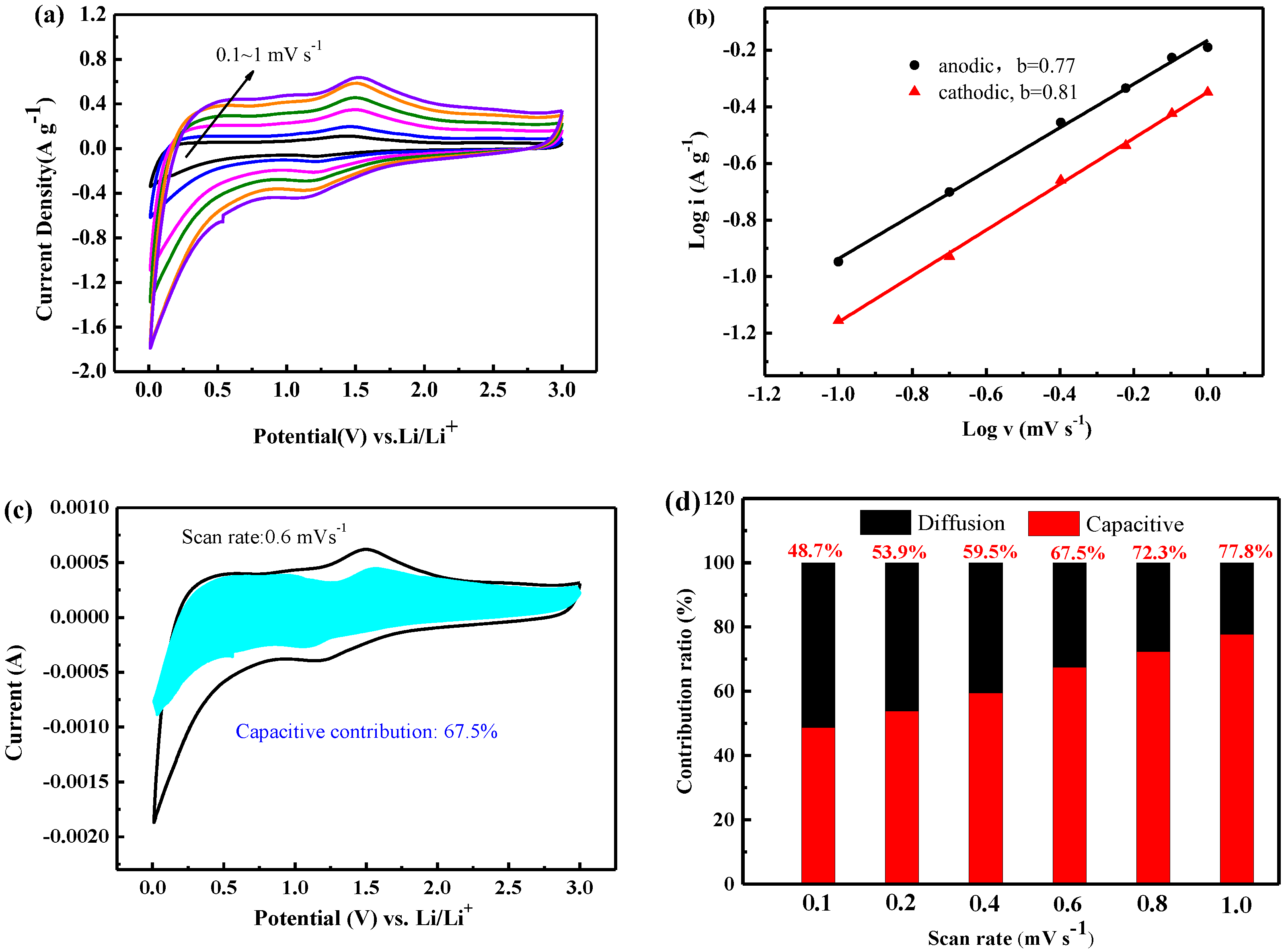
In order to gain additional understanding of the lithium storage mechanism of MON-QD/NG-600, CV curves at different scan rates from 0.1 to 1 mV s−1 were tested. As shown in Figure 9a, the CV curves at different scan rates exhibit a pair of redox peaks between 1.0 and 1.7 V. Obviously, the height and area of redox peak increase as the scan rate increases, which is due to electrode capacity obtained by dividing the peak area by scan rate which should be constant [37,38]. In addition, it can be observed that the oxidation peak shifted to higher potential slightly while the corresponding reduction peak shifted to a lower potential slightly, indicating that the MON-QD/NG-600 electrode showed increasingly obvious irreversible reaction at relatively high scan rates. Hence, the Randles–Ševčík equation (Equation (1)) was applied to calculate the diffusion constant D, which can well describe the relationship between square root of the scan rate v1/2 and peak current ip:
i p = 2.69 × 10 5 n 3 / 2 A D L i 1 / 2 v 1 / 2 Δ C o
where i p is the peak current, A is the effective contact area between the electrode and electrolyte (cm2), n is the number of electrons involved in the reaction, D L i is the diffusion coefficient of Li+ (cm2 s−1), v is the scan rate (V s−1), Δ C o is the change in Li+ concentration in the electrode before and after the reaction (mol cm−3). According to Equation (1), the Li+ diffusion coefficients of the electrochemical reaction corresponding to the anodic and cathodic peaks are 4.08 × 10⁻¹⁰ and 4.71 × 10⁻¹⁰ cm2 s−1, respectively. Obviously, the Li+ diffusion coefficients of anodic and cathodic reaction have the same order of magnitude, indicating the excellent reversibility of the MON-QD/NG-600 electrode. Usually, the stored charge of an electrode can be divided into three components: (1) the faradaic contribution due to Li+ insertion process, (2) the faradaic contribution caused by charge transfer behavior, (3) the double layer capacitance. Generally, (1) and (2) are grouped into the same monomial, namely, the capacity-controlled process and the diffusion-controlled process. The current (i) and the scan rate (v) obey the power law in the CV curves, which can be proved by Equations (2) and (3) [39]:
i = a v b
log ( i ) = blog ( v ) + log ( a )
where a and b are variables. The b value can be determined by the slope of the plot log (i) versus log (v) curves [40]. b = 0.5 indicates a diffusion-controlled behavior, whereas b = 1 reflects that the electrochemical reaction is controlled by a capacitance-dominated process. As shown in Figure 9b, the slopes of the anodic and cathodic peak are 0.77 and 0.81, respectively, indicating fast kinetics contributed by both behaviors. Therefore, there is a good relationship between v 1 / 2 and i p . Hence, the CV curves with different scan rates can be used to quantitatively calculate the capacitive contribution by using Equation (4) [41,42]:
i = k 1 v + k 2 v 1 / 2   ( equivalent   to   i v 1 / 2 = k 1 v 1 / 2 + k 2 )
where k is a constant. k 1 v and k 2 v 1 / 2 are consistent with the contribution of the capacitance effect and the diffusion-controlled behavior, respectively [43]. The contribution of the capacitive process was also calculated. As shown in Figure 9c, the capacitive process contributes about 67.5% of the total capacity at a scan rate of 0.6 mV s−1. The contribution ratios of the two processes at various scan rates were also incidentally calculated. The capacitive contribution progressively increases from 48.7% at 0.1 mV s−1 to a maximum value of 77.8% at 1 mV s−1, as shown in Figure 9d. With the consideration of these, it shows that most of the charge stored in MON-QD/NG-600 was a capacitive process. This characteristic is highly beneficial for the fast transport of Li+, resulting in high reversible rate performance and cycling performance.

4. Conclusions

MON-QD/NG was successfully synthesized through a green and facile hydrothermal route, followed by an annealing process. The electrochemical lithium storage performance test of electrode materials indicates that temperature has a great influence on the growth of Mo2N and MoO2. The content of MoO2 in the composite increases with the increase in temperature. However, the poor conductivity of MoO2 affects the electrochemical performance of the materials. Therefore, MON-QD/NG-600 has the best lithium storage performance. It has a reversible capacity of about 958.9 mAh g−1 at current density of 0.1 A g−1, and even has a reversible capacity of about 350.5 mAh g−1 and 297.2 mAh g−1 at 2 A g−1 and 5 A g−1, respectively. The characterization of MON-QD/NG-600 found that the prepared Mo2N and MoO2 exist in the shape of quantum dots with size of about 1–3 nm. The quantum dots inhibit the volume change in materials during charging and discharging, reduce the diffusion path of lithium ions as well as prevent the agglomeration between graphene sheets effectively. Moreover, the distribution of quantum dots on or between graphene sheets also provides a large number of reaction sites for electrochemical reactions. Due to the unique structure and synergy of Mo2N and MoO2, MON-QD/NG-600 exhibits excellent lithium storage performance in terms of stable long cycle life and superior rate capability. Therefore, the MON-QD/NG composite can be used as a promising electrode material candidate for high-performance LIBs.

Supplementary Materials

The following supporting information can be downloaded at: https://www.mdpi.com/article/10.3390/batteries9010032/s1, Figure S1: Charge-discharge curves of different current density; Figure S2: Some selected charge-discharge curves (the first, 100, 200 and 300 cycles) during cycling tests at 5 A g-1 of MON- QD/NG-600; Table S1: The comparison of molybdenum nitride related anode material for lithium ion battery [44,45,46].

Author Contributions

Conceptualization, L.W. and L.Z.; methodology, H.F.; software, Y.C.; formal analysis, T.Z.; investigation, R.C. and Y.Y. All authors have read and agreed to the published version of the manuscript.

Funding

This work is financially supported by Science and Technology Project of Henan Province (Nos. 212102210649, 212102210648, 222102240122).

Informed Consent Statement

Not applicable.

Data Availability Statement

Not applicable.

Conflicts of Interest

The authors declare no conflict of interest. We declare that we do not have any commercial or associative interest that represents a conflict of interest in connection with the work submitted.

References

  1. Wang, L.; Zhang, K.; Pan, H.; Wang, L.; Wang, D.; Dai, W.; Qin, H.; Li, G.; Zhang, J. 2D molybdenum nitride nanosheets as anode materials for improved lithium storage. Nanoscale 2018, 10, 18936–18941. [Google Scholar] [CrossRef] [PubMed]
  2. Nandi, D.K.; Sen, U.K.; Choudhury, D.; Mitra, S.; Sarkar, S.K. Atomic Layer Deposited Molybdenum Nitride Thin Film: A Promising Anode Material for Li Ion Batteries. ACS Appl. Mater. Interfaces 2014, 6, 6606–6615. [Google Scholar] [CrossRef] [PubMed]
  3. Park, H.-C.; Lee, K.-H.; Lee, Y.-W.; Kim, S.-J.; Kim, D.-M.; Kim, M.-C.; Park, K.-W. Mesoporous molybdenum nitride nanobelts as an anode with improved electrochemical properties in lithium ion batteries. J. Power Sources 2014, 269, 534–541. [Google Scholar] [CrossRef]
  4. Joshi, S.; Qi, W.; Puntambekar, A.; Chakrapani, V. Facile Synthesis of Large Area Two Dimensional Layers of Transition Metal Nitride and Their Use as Insertion Electrodes. ACS Energy Lett. 2018, 2, 1257–1262. [Google Scholar] [CrossRef]
  5. Ji, L.; Lin, Z.; Alcoutlabi, M.; Zhang, X. Recent developments in nanostructured anode materials for rechargeable lithium-ion batteries. Energy Environ. Sci. 2011, 4, 2682–2699. [Google Scholar] [CrossRef]
  6. Wu, H.; Zheng, G.; Liu, N.; Carney, T.J.; Yang, Y.; Cui, Y. Engineering Empty Space between Si Nanoparticles for Lithium-Ion Battery Anodes. Nano Lett. 2012, 12, 904–909. [Google Scholar] [CrossRef] [Green Version]
  7. Dang, W.; Wang, W.; Yang, Y.; Wang, Y.; Huang, J.; Fang, X.; Wu, L.P.; Rong, Z.H.; Chen, X.; Li, X.; et al. One-step hydrothermal synthesis of 2D WO3 nanoplates@ graphene nanocomposite with superior anode performance for lithium ion battery. Electrochim. Acta 2019, 313, 99–108. [Google Scholar] [CrossRef]
  8. Xu, H.; Zhang, H.; Fang, L.; Yang, J.; Wu, K.; Wang, Y. Hierarchical Molybdenum Nitride Nanochexes by a Textured Self-Assembly in Gas-Solid Phase for the Enhanced Application in Lithium Ion Batteries. ACS Nano 2015, 9, 6817–6825. [Google Scholar] [CrossRef]
  9. Sun, Y.; Zhou, Y.; Zhu, Y.; Shen, Y.; Xie, A. In-Situ Synthesis of Petal-Like MoO2@MoN/NF Heterojunction As Both an Advanced Binder-Free Anode and an Electrocatalyst for Lithium Ion Batteries and Water Splitting. ACS Sustain. Chem. Eng. 2019, 7, 9153–9163. [Google Scholar] [CrossRef]
  10. Li, L.; Jia, X.N.; Zhang, Y.; Qiu, T.Y.; Hong, W.W.; Jiang, Y.L.; Zou, G.Q.; Hou, H.S.; Chen, X.C.; Ji, X.B. Li4Ti5O12 quantum dot decorated carbon frameworks from carbon dots for fast lithium ion storage. Mat. Chem. Front. 2019, 3, 1761–1767. [Google Scholar] [CrossRef]
  11. Zhang, B.; Cui, G.; Zhang, K.; Zhang, L.; Han, P.; Dong, S. Molybdenum nitride/nitrogen-doped graphene hybrid material for lithium storage in lithium ion batteries. Electrochim. Acta 2014, 150, 15–22. [Google Scholar] [CrossRef]
  12. Zhang, Q.H.; Zhang, X.D.; He, W.; Xu, G.G.; Ren, M.M.; Liu, J.H.; Yang, X.N.; Wang, F. In situ fabrication of Na3V2(PO4)(3) quantum dots in hard carbon nanosheets by using lignocelluloses for sodium ion batteries. J. Mater. Sci. Technol. 2019, 35, 2396–2403. [Google Scholar] [CrossRef]
  13. Pan, X.; Xi, B.; Lu, H.; Zhang, Z.; An, X.; Liu, J.; Feng, J.; Xiong, S. Molybdenum Oxynitride Atomic Nanoclusters Bonded in Nanosheets of N-Doped Carbon Hierarchical Microspheres for Efficient Sodium Storage. Nanomicro Lett. 2022, 14, 163. [Google Scholar] [CrossRef] [PubMed]
  14. Gayathri, V.; Peter, I.J. Graphene Quantum Dots Supported Mo3S4 as a Promising Candidate for Pt-Free Counter Electrode in Dye-Sensitized Solar Cell and Supercapacitor Applications. ECS J. Solid State Sci. Technol. 2021, 10, 091002. [Google Scholar] [CrossRef]
  15. Kumar, R.; Bhuvana, T.; Sharma, A. Ammonolysis synthesis of nickel molybdenum nitride nanostructures for high-performance asymmetric supercapacitors. New J. Chem. 2020, 44, 14067–14074. [Google Scholar] [CrossRef]
  16. He, T.; Zhang, W.; Manasa, P.; Ran, F. Quantum dots of molybdenum nitride embedded in continuously distributed polyaniline as novel electrode material for supercapacitor. J. Alloys Compd. 2020, 812, 152138. [Google Scholar] [CrossRef]
  17. Borah, D.J.; Mostako, A.T.T.; Borgogoi, A.T.; Saikia, P.K.; Malakar, A. Modified top-down approach for synthesis of molybdenum oxide quantum dots: Sonication induced chemical etching of thin films. RSC Adv. 2020, 10, 3105–3114. [Google Scholar] [CrossRef]
  18. Zheng, C.; Luo, N.; Huang, S.; Wu, W.; Huang, H.; Wei, M. Nanocomposite of Mo2N Quantum Dots@MoO3@Nitrogen-Doped Carbon as a High-Performance Anode for Lithium-Ion Batteries. ACS Sustain. Chem. Eng. 2019, 7, 10198–10206. [Google Scholar] [CrossRef]
  19. Liu, J.; Tang, S.; Lu, Y.; Cai, G.; Liang, S.; Wang, W.; Chen, X. Synthesis of Mo2N nanolayer coated MoO2 hollow nanostructures as high-performance anode materials for lithium-ion batteries. Energy Environ. Sci. 2013, 6, 2691–2697. [Google Scholar] [CrossRef]
  20. Afanasiev, P. New single source route to the molybdenum nitride Mo(2)N. Inorg. Chem. 2002, 41, 5317–5319. [Google Scholar] [CrossRef]
  21. Akhmetzyanova, U.; Pelíšková, L.; Skuhrovcová, L.; Tišler, Z.; Opanasenko, M. Molybdenum Nitrides, Carbides and Phosphides as Highly Efficient Catalysts for the (hydro)Deoxygenation Reaction. ChemistrySelect 2019, 4, 8453. [Google Scholar] [CrossRef]
  22. Wang, L.; Zhang, Z.; Li, L.; Zhang, L.; Fang, H.; Song, Y.; Li, X. Preparation and lithium storage properties of Mo2N quantum dots@nitrogen-doped graphene composite. CIESC J. 2020, 71, 5854–5862. [Google Scholar] [CrossRef]
  23. Marcano, D.C.; Kosynkin, D.V.; Berlin, J.M.; Alexander, S.; Zhengzong, S.; Alexander, S.; Alemany, L.B.; Wei, L.; Tour, J.M. Improved synthesis of graphene oxide. ACS Nano 2010, 4, 4806. [Google Scholar] [CrossRef]
  24. Zheng, C.; Liu, M.; Chen, W.; Zeng, L.; Wei, M. An in situ formed Se/CMK-3 composite for rechargeable lithium-ion batteries with long-term cycling performance. J. Mater. Chem. A 2016, 4, 13646–13651. [Google Scholar] [CrossRef]
  25. Liu, X.B.; Amiinu, I.S.; Liu, S.J.; Pu, Z.H.; Li, W.Q.; Ye, B.; Tan, D.M.; Mu, S.C. H2O2-Assisted Synthesis of Porous N-Doped Graphene/Molybdenum Nitride Composites with Boosted Oxygen Reduction Reaction. Adv. Mater. Interfaces 2017, 4, 8. [Google Scholar] [CrossRef]
  26. Liang, J.; Zhao, J.; Li, Y.; Lee, K.-T.; Liu, C.; Lin, H.; Cheng, Q.; Lan, Q.; Wu, L.; Tang, S.; et al. In situ SiO2 etching strategy to prepare rice husk-derived porous carbons for supercapacitor application. J. Taiwan Inst. Chem. Eng. 2017, 81, 383–390. [Google Scholar] [CrossRef]
  27. Maldonado, S.; Morin, S.; Stevenson, K.J. Structure, composition, and chemical reactivity of carbon nanotubes by selective nitrogen doping. Carbon 2006, 44, 1429–1437. [Google Scholar] [CrossRef]
  28. Zhang, Q.; Li, X.; Ma, Q.; Zhang, Q.; Bai, H.; Yi, W.; Liu, J.; Han, J.; Xi, G. A metallic molybdenum dioxide with high stability for surface enhanced Raman spectroscopy. Nat. Commun. 2017, 8, 14903. [Google Scholar] [CrossRef] [Green Version]
  29. Peng, T.; Tan, Z.; Zhang, M.; Li, L.; Wang, Y.; Guan, L.; Tan, X.; Pan, L.; Fang, H.; Wu, M. Facile and cost-effective manipulation of hierarchical carbon nanosheets for pseudocapacitive lithium/potassium storage. Carbon 2020, 165, 296–305. [Google Scholar] [CrossRef]
  30. Wang, C.; Jiang, J.; Ruan, Y.; Ao, X.; Ostrikov, K.; Zhang, W.; Lu, J.; Li, Y.Y. Construction of MoO2 Quantum Dot-Graphene and MoS2 Nanoparticle-Graphene Nanoarchitectures toward Ultrahigh Lithium Storage Capability. ACS Appl. Mater. Interfaces 2017, 9, 28441–28450. [Google Scholar] [CrossRef]
  31. Shi, W.; Zhu, J.; Rui, X.; Cao, X.; Chen, C.; Zhang, H.; Hng, H.H.; Yan, Q. Controlled synthesis of carbon-coated cobalt sulfide nanostructures in oil phase with enhanced li storage performances. ACS Appl Mater. Interfaces 2012, 4, 2999–3006. [Google Scholar] [CrossRef]
  32. Liang, Y.; Chen, Y.; Ke, X.; Zhang, Z.; Wu, W.; Lin, G.; Zhou, Z.; Shi, Z. Coupling of triporosity and strong Au–Li interaction to enable dendrite-free lithium plating/stripping for long-life lithium metal anodes. J. Mater. Chem. A 2020, 8, 18094–18105. [Google Scholar] [CrossRef]
  33. Liu, G.; Yang, Y.; Lu, X.; Qi, F.; Liang, Y.; Trukhanov, A.; Wu, Y.; Sun, Z.; Lu, X. Fully Active Bimetallic Phosphide Zn0.5Ge0.5P: A Novel High-Performance Anode for Na-Ion Batteries Coupled with Diglyme-Based Electrolyte. ACS Appl. Mater. Interfaces 2022, 14, 31803–31813. [Google Scholar] [CrossRef]
  34. Ali, Y.; Lee, S. An integrated experimental and modeling study of the effect of solid electrolyte interphase formation and Cu dissolution on CuCo2O4-based Li-ion batteries. Int. J. Energy Res. 2021, 46, 3017–3033. [Google Scholar] [CrossRef]
  35. Wang, F.-M.; Rick, J. Synergy of Nyquist and Bode electrochemical impedance spectroscopy studies to commercial type lithium ion batteries. Solid State Ion. 2014, 268, 31–34. [Google Scholar] [CrossRef]
  36. Ogihara, N.; Kawauchi, S.; Okuda, C.; Itou, Y.; Takeuchi, Y.; Ukyo, Y. Theoretical and Experimental Analysis of Porous Electrodes for Lithium-Ion Batteries by Electrochemical Impedance Spectroscopy Using a Symmetric Cell. J. Electrochem. Soc. 2012, 159, A1034–A1039. [Google Scholar] [CrossRef]
  37. Rui, X.H.; Li, C.; Liu, J.; Cheng, T.; Chen, C.H. The Li3V2(PO4)(3)/C composites with high-rate capability prepared by a maltose-based sot-gel route. Electrochim. Acta 2010, 55, 6761–6767. [Google Scholar] [CrossRef]
  38. Zhu, L.; Zhang, M.; Yang, L.; Zhou, K.; Wang, Y.; Sun, D.; Tang, Y.; Wang, H. Engineering hierarchical structure and surface of Na4MnV(PO4)3 for ultrafast sodium storage by a scalable ball milling approach. Nano Energy 2022, 99, 107396. [Google Scholar] [CrossRef]
  39. Wang, J.; Polleux, J.; Lim, J.; Dunn, B. Pseudocapacitive Contributions to Electrochemical Energy Storage in TiO2 (Anatase) Nanoparticles. J. Phys. Chem. C 2007, 111, 14925–14931. [Google Scholar] [CrossRef]
  40. Li, H.; Lang, J.; Lei, S.; Chen, J.; Wang, K.; Liu, L.; Zhang, T.; Liu, W.; Yan, X. A High-Performance Sodium-Ion Hybrid Capacitor Constructed by Metal-Organic Framework-Derived Anode and Cathode Materials. Adv. Funct. Mater. 2018, 28, 1800757. [Google Scholar] [CrossRef]
  41. Das, S.R.; Majumder, S.B.; Katiyar, R.S. Kinetic analysis of the Li+ ion intercalation behavior of solution derived nano-crystalline lithium manganate thin films. J. Power Sources 2005, 139, 261–268. [Google Scholar] [CrossRef]
  42. Veronica, A.; Jérémy, C.; Lowe, M.A.; Jong Woung, K.; Pierre-Louis, T.; Tolbert, S.H.; Abruña, H.D.; Patrice, S.; Bruce, D. High-rate electrochemical energy storage through Li+ intercalation pseudocapacitance. Nat. Mater. 2013, 12, 518. [Google Scholar]
  43. Zhu, T.; Wang, Y.; Li, Y.; Cai, R.; Zhang, J.; Yu, C.; Wu, J.; Cui, J.; Zhang, Y.; Ajayan, P.M.; et al. CoO Quantum Dots Anchored on Reduced Graphene Oxide Aerogels for Lithium-Ion Storage. ACS Appl. Nano Mater. 2020, 3, 10369–10379. [Google Scholar] [CrossRef]
  44. Wang, L.; Li, L.; Guo, X.; Zhang, J.; Liu, P.; Yan, J. Porous Mo2N nano-column array thin film electrode for lithium ion storage. Results Phys. 2019, 15, 102715. [Google Scholar] [CrossRef]
  45. Ji, W.; Shen, R.; Yang, R.; Yu, G.; Guo, X.; Peng, L.; Ding, W. Partially nitrided molybdenum trioxide with promoted performance as an anode material for lithium-ion batteries. J. Mater. Chem. A 2014, 2, 699–704. [Google Scholar] [CrossRef]
  46. Zhou, D.; Wu, H.; Wei, Z.; Han, B.H. Graphene-molybdenum oxynitride porous material with improved cyclic stability and rate capability for rechargeable lithium ion batteries. Phys. Chem. Chem. Phys. 2013, 15, 16898–16906. [Google Scholar] [CrossRef]
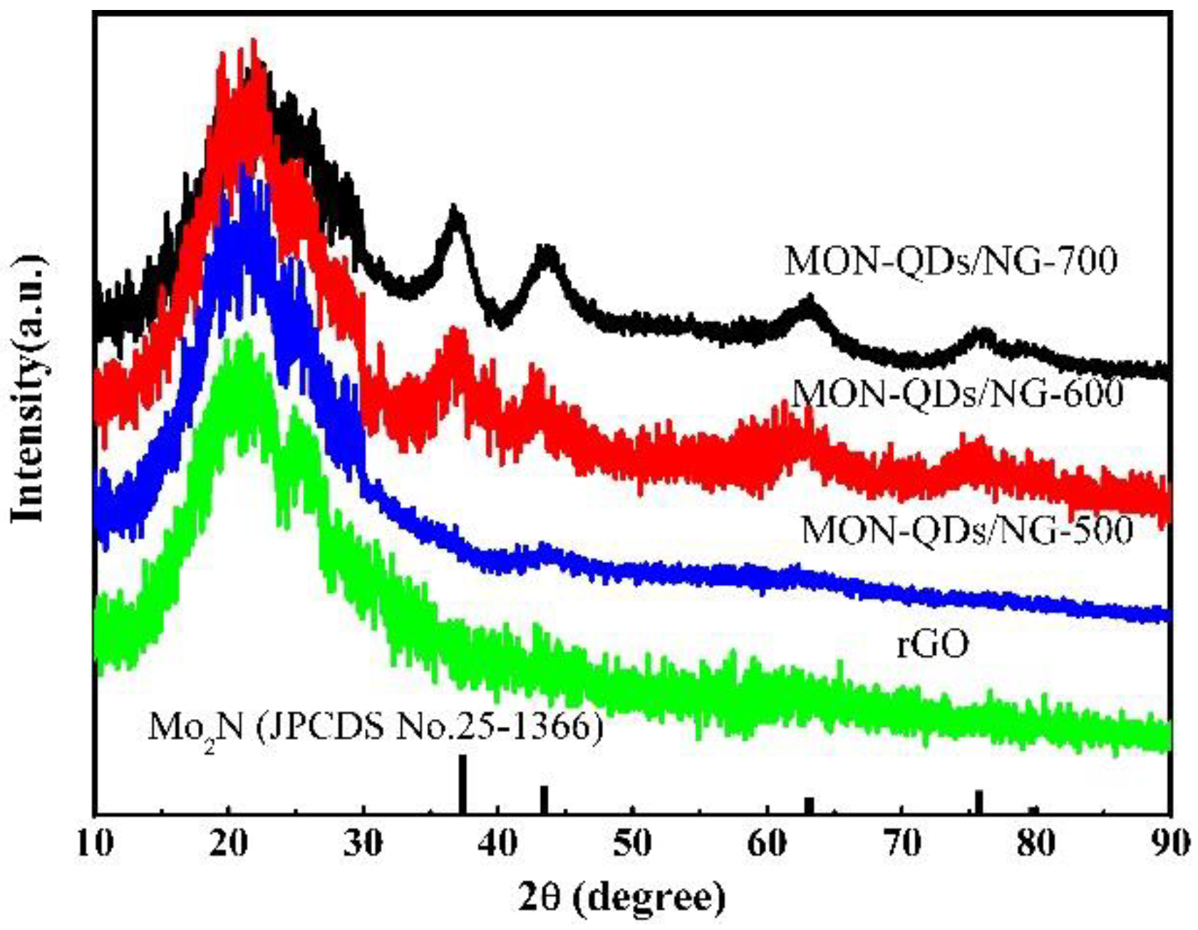
Figure 1. XRD pattern of MON-QD/NG, rGO and the standard card of face-centered cubic Mo2N.
Batteries 09 00032 g001
Figure 2. Raman spectra of MON-QD/NG at different calcination temperatures (a,b).
Batteries 09 00032 g002
Figure 3. XPS spectra of MON-QD/NG-600 sample: (a) survey; (b) O1s; (c) N1s; (d) C1s; (e) Mo3d spectrum of MON-QD/NG-500; (f) Mo3d spectrum of MON-QD/NG-600; (g) Mo3d spectrum of MON-QD/NG-700.
Batteries 09 00032 g003aBatteries 09 00032 g003b
Figure 4. Morphology of MON-QD/NG-600: (a) SEM; (b) TEM; (c) HRTEM; (d) SAED.
Batteries 09 00032 g004
Figure 5. BET tests: (a) The adsorption and desorption isothermal curves of three MON-QD/NG composite materials; (b) pore size distribution.
Batteries 09 00032 g005
Figure 6. CV curves of MON-QD/NG-600 composite material.
Batteries 09 00032 g006
Figure 7. Charge and discharge curves of composite materials at different calcination temperatures: (a) MON-QD/NG-500; (b) MON-QD/NG-600; (c) MON-QD/NG-700.
Batteries 09 00032 g007
Figure 8. Electrochemical performance of electrode materials at different calcination temperatures: (a) rate performance and cycling stability at 5 A g−1; (b) Nyquist plots of electrode materials.
Batteries 09 00032 g008
Figure 9. Kinetics analysis of the electrochemical performance toward Li+ for the MON-QD/NG-600 electrode: (a) CV curves at scan rates from 0.1 to 1.0 mV s−1; (b) the corresponding relationship between the scan rate and peak current; (c) CV curves and capacitive contribution to the total charge storage of MON-QD/NG-600 electrode at 0.6 mVs−1; (d) contribution ratios of the capacitive and diffusion-controlled capacities at different scan rates.
Batteries 09 00032 g009
Disclaimer/Publisher’s Note: The statements, opinions and data contained in all publications are solely those of the individual author(s) and contributor(s) and not of MDPI and/or the editor(s). MDPI and/or the editor(s) disclaim responsibility for any injury to people or property resulting from any ideas, methods, instructions or products referred to in the content.