Article

Mitigating Polysulfide Shuttles with Upcycled Alkali Metal Terephthalate Decorated Separators

Davidson School of Chemical Engineering, Purdue University, West Lafayette, IN 47907, USA
*
Author to whom correspondence should be addressed.
Batteries 2022, 8(12), 253; https://doi.org/10.3390/batteries8120253
Submission received: 19 October 2022 / Revised: 11 November 2022 / Accepted: 17 November 2022 / Published: 23 November 2022
(This article belongs to the Collection Advances in Battery Materials)

Abstract

:
High energy density lithium–sulfur batteries (LSBs) are a potential replacement for lithium-ion batteries (LIBs). However, practical lifetimes are inhibited by lithium polysulfide (LiPS) shuttling. Concurrently, plastic waste accumulation worldwide threatens our ecosystems. Herein, a fast and facile strategy to upcycle polyethylene terephthalate (PET) waste into useful materials is investigated. Dilithium terephthalate (Li2TP) and dipotassium terephthalate (K2TP) salts were synthesized from waste soda bottles via microwave depolymerization and solution coated onto glass fiber paper (GFP) separators. Salt-functionalized separators with Li2TP@GFP and K2TP@GFP mitigated LiPS shuttling and improved electrochemical performance in cells. Pore analysis and density functional theory (DFT) calculations indicate the action mechanism is synergistic physical blocking of bulky LiPS anions in nanopores and diffusion inhibition via electrostatic interactions with abundant carboxylate groups. LSBs with K2TP@GFP separator showing highest LiPS affinity and smallest pore size demonstrated enhanced initial capacity as compared to non-modified GFP by 5.4% to 648 mAh g−1, and increased cycle 100 capacity by 23% to 551 mAh g−1. Overall, K2TP@GFP retained 85% of initial capacity after 100 cycles with an average capacity fading of 0.15% per cycle. By comparison, GFP retained only 73% of initial capacity after 100 cycles with 0.27% average capacity loss, demonstrating effective LiPS retention.

1. Introduction

As portable electronics become more ubiquitous in our daily lives for everything from communication to transportation, there is a corresponding increased demand for enhanced energy density from rechargeable batteries. Although the capacity of cell phone batteries has been steadily increasing due to optimizations of current LIBs and cell design, they have not managed to significantly outpace growing power demands of more powerful processers and larger screens, much to the frustration of consumers who still recharge their devices every night [1]. Additionally, for defense applications, higher energy density electrochemical energy storage could provide critical advantages on the battlefield by allowing greater mission times involving portable communications or by enabling longer flight times for reconnaissance drones [2]. Unfortunately, LIB technology is approaching its limit since its entrance into the market in 1991. Although the energy density of LIBs has continued to see incremental improvements due to optimizations in cell packaging and design, these marginal increases bring the technology ever closer to the maximum theoretical energy density [3]. A disruptive improvement in electrochemical energy storage has the potential to revolutionize transportation and information logistics as well as the way electronic devices are integrated into our lifestyles. Towards this end, there have been considerable efforts towards exploring alternative secondary battery chemistries which can outperform the current state-of-the-art LIBs [4,5].
One subsequent research area of interest is the promising LSB. Whereas LIBs have a maximum theoretical energy density of 570 Wh kg−1, LSBs may theoretically reach up to 2600 Wh kg−1 due to the much higher energy density of both the electrode materials. The sulfur cathode can store a maximum of 1675 mAh g−1, and the lithium anode 3860 mAh g−1. This is significantly higher than the current cobalt oxide cathode and graphite anodes which can only store 274 and 376 mAh g−1, respectively [6,7]. Furthermore, sulfur is cost effective at approximately USD100–150 ton−1 versus cobalt at about USD10,000–75,000 ton−1 and geographically widespread, whereas cobalt is primarily mined in the Congo and plagued by controversy [8,9]. However, LSBs also suffer from poor utilization of the cathode material; although in this case, the difficulty arises from the poor electronic conductivity of elemental sulfur rather than changes in crystal structure of the metal oxide. Soluble LiPS species dissolve in the electrolyte and shuttle to the Li anode, which leads to poor coulombic efficiencies (CE) and cycle lifetimes, precluding commercial integration of LSBs [8,10,11].
Various strategies have been tested to address these fundamental issues. One of the most popular methods is to host the sulfur cathode in a carbon scaffold. The high surface area, electronic conductivity, and affinity for LiPSs can mitigate issues surrounding the poor electronic conductivity and LiPS diffusion, thereby improving the material utilization, coulombic efficiency, and capacity retention [8,11,12,13,14]. This strategy alone, however, has not been able to reach the cycle lifetimes required for marketable batteries. Therefore, on top of this, researchers have further investigated active material coatings [15,16,17], functional binders or carbons [14,18,19], and electrolyte optimization [20,21,22,23] with varying levels of success. A simpler strategy that has also proven efficacious is the use of functionalized separators which can block or trap LiPSs based on concepts of size-exclusion and chemical affinity [24,25,26,27]. Overall, there have been extensive efforts spent towards development of materials with high porosities and strong interactions with LiPSs. Many results in the literature, however, feature complicated nanomaterial syntheses [28], energy intensive carbonization processes [29], and costly transition metals [30]. Further these materials are often coated onto the separator using environmentally hostile solvents and polymers [31].
At the same time, there is a separate concern growing over the use of plastics. Industrial plastics have revolutionized manufacturing and facilitated significant improvements in quality of life. Heralded as miracle materials for their facile processing, strength, and resiliency, over 250 million tons of plastic are produced every year [32]. Much of this is for single-use plastics which often end up in the landfill or as pollutants in the ocean. Globally, more than 80 million tons of polyethylene terephthalate (PET) is produced each year to make single-use bottles, packaging, and fabrics. Of this, less than 30% is recycled [32,33]. The same chemical resiliency that makes plastics desirable unfortunately also complicates recycling, and harsh conditions are often required to revert the long polymer chains back to their monomer constituents.
In this study, we present a strategy to simultaneously remove PET from the waste stream and enhance the electrochemical performance of LSBs. By using a quick and facile microwave process in the presence of alkali metal hydroxides, we return PET to dilithium terephthalate (Li2TP) and dipotassium terephthalate (K2TP) monomer salts rich in carboxylate functional groups. Through a benign aqueous dip-coating procedure, these materials decorate glass fiber paper (GFP) separator, as shown in the schematic in Figure 1. During electrochemical cycling in a LSBs, the high specific surface area, polar functional groups, and nanopores effectively block the diffusion of LiPSs to the anode, as verified ex situ with a separator diffusion test. DFT calculations also indicate the high binding energy for geometrically optimized LiPSs to terephthalate salts (TPS). K2TP coated separator performed the best with the highest specific surface area and improved 100 cycle capacity retention from 73 to 85% as compared to uncoated GFP.

2. Results and Discussion

2.1. Material Characterizations

Alkali terephthalates are produced with a non-aqueous microwave synthesis as demonstrated in our prior publications [34,35]. In the saponification reaction, PET soda bottle flakes were combined with lithium hydroxide and potassium hydroxide in glycol solvent, irradiated, and washed with ethanol to produce Li2TP and K2TP salts, respectively. Verification and characterization of the as-synthesized materials are shown in Figure 2. FTIR analysis in Figure 2a shows spectra of the PET soda bottle flake precursor as well as the synthesized Li2TP and K2TP products. PET spectra match literature, with peaks at 724 and 872 cm−1 corresponding to bending of the aromatic and disubstituted hydrogens, at 1095 and 1242 cm−1 for the stretching of aliphatic and aromatic ethers, and at 1715 cm−1 for the stretching of the ketone functional group [36]. For Li2TP, a peak appears at 752 cm−1 for the bending of the carboxylate group [37]. For K2TP, however, this peak is redshifted to 742 cm−1 due to weaker ionic bonding with the bulky potassium ion. This downward shift in wavenumber is mirrored in peaks corresponding to symmetric stretching of the carboxylate groups at 1300 and 1391 cm−1 for Li2TP. Wavenumbers for Li2TP corresponding to bending of the benzene rings at 825 cm−1 and stretching of the phenyl carbon bond at 1501 cm−1, conversely, are very similar to those of the K2TP as they are less affected by substitution of the cation [34,35,37]. SEM images in Figure 2b,c for Li2TP and K2TP, respectively, show the latter favors forms small sheet-like crystals, the majority being sub-micron sized and less than 100 nm in thickness. Li2TP, conversely, forms much larger and regular rod-like crystals up to 40 microns or more in length and can reach over 15 microns in diameter. Nitrogen adsorption/desorption was further performed on the materials to investigate physical surface properties. Measured BET surface areas of the Li2TP and K2TP are 1.85 and 13.5 m2 g−1, respectively, as shown in Figure 2d,e. High surface area increases opportunity for electrostatic interactions of LiPSs with the negatively charged carboxylate groups [19]. In addition to higher surface area, K2TP shows a much higher cumulative pore volume (Figure 2f). The lower pore size limits measured for Li2TP and K2TP are 2.4 and 1.6 nm, respectively. Literature suggests nanopores can inhibit the diffusion of LiPSs through ionic sieving. Estimates for the size of LiPS anions range from <1 to 2.39 nm, and even slightly larger pores may still effectively restrict anion transport [25,38,39,40]. We posit, therefore, that nanopores for K2TP may be effective in physically blocking large LiPSs.

2.2. Separator Characterizations

Modified glass fiber separators denoted Li2TP@GFP and K2TP@GFP are decorated via dip-coating using a 5 wt.% aqueous solution of either Li2TP or K2TP, respectively, and subsequently dried. Areal mass loadings of coated Li2TP@GFP and K2TP@GFP separators were measured to be 1.64 ± 0.26 and 1.65 ± 0.59 mg cm−2, respectively, with error representing the standard deviation of 3 samples. The presence of TPS on the separators is further confirmed in Figure 3. FTIR spectra of undecorated and decorated GFP separators in Figure 3a reveal a broad peak centered around approximately 1000 cm−1 for GFP, corresponding to stretching of surface hydroxyl groups [41]. After coating, the strong peaks corresponding to the symmetric and asymmetric stretching of the carboxylate groups on the terephthalates can be identified [34,35,37]. SEM images also confirm the loading of TPS. Figure 3b shows the default GFP separator, with visible glass fibers. Li2TP on Li2TP@GFP takes on an amorphous shape, with large, aggregated globules several microns in size sporadically coating the fibers (Figure 3c). In comparison, K2TP coating on K2TP@GFP remains as micron-sized particles on the fiberglass threads (Figure 3d). The flaky particles more evenly coat the fibers and appear homogeneously distributed.
Separator diffusion experiments were conducted to confirm the ability of the modified separators to inhibit LiPS transport. Over the course of 3 h, polysulfides from a 0.25 M Li2S6 solution diffuse across the separator into the clean DOL:DME solution, which is then analyzed. Figure 3e shows light absorption spectra for the effluent solutions. Highest absorbance and, thus, the highest LiPS concentration is seen for bare GFP. Conversely, K2TP@GFP separator shows the lowest absorbance, demonstrating the ability to inhibit the diffusion of LiPSs.
The ability of charged functional groups, including nucleophilic alcohol and carboxyl groups, to aid LiPS immobilization is well-established [8,19,24,25,26]. Cation selective transport aided by solid ceramic additives or acidic groups also helps prevent migration of PS anions to the anode [25]. When hydrogen on acidic carboxyl or sulfonate functional groups is substituted for an alkali ion, this effect can be further enhanced, providing higher ionic conductivities, higher lithium transference, and inhibited LiPS diffusion [42,43]. Vediappan et al. found enhanced cation transport in Li2TP over terephthalic acid [44]. It is, therefore, reasonable to extrapolate that our Li2TP@GFP and K2TP@GFP separator with the same or similar functional groups will provide similar advantages mechanistically in a LSB.

2.3. Electrochemical Cycling Analysis

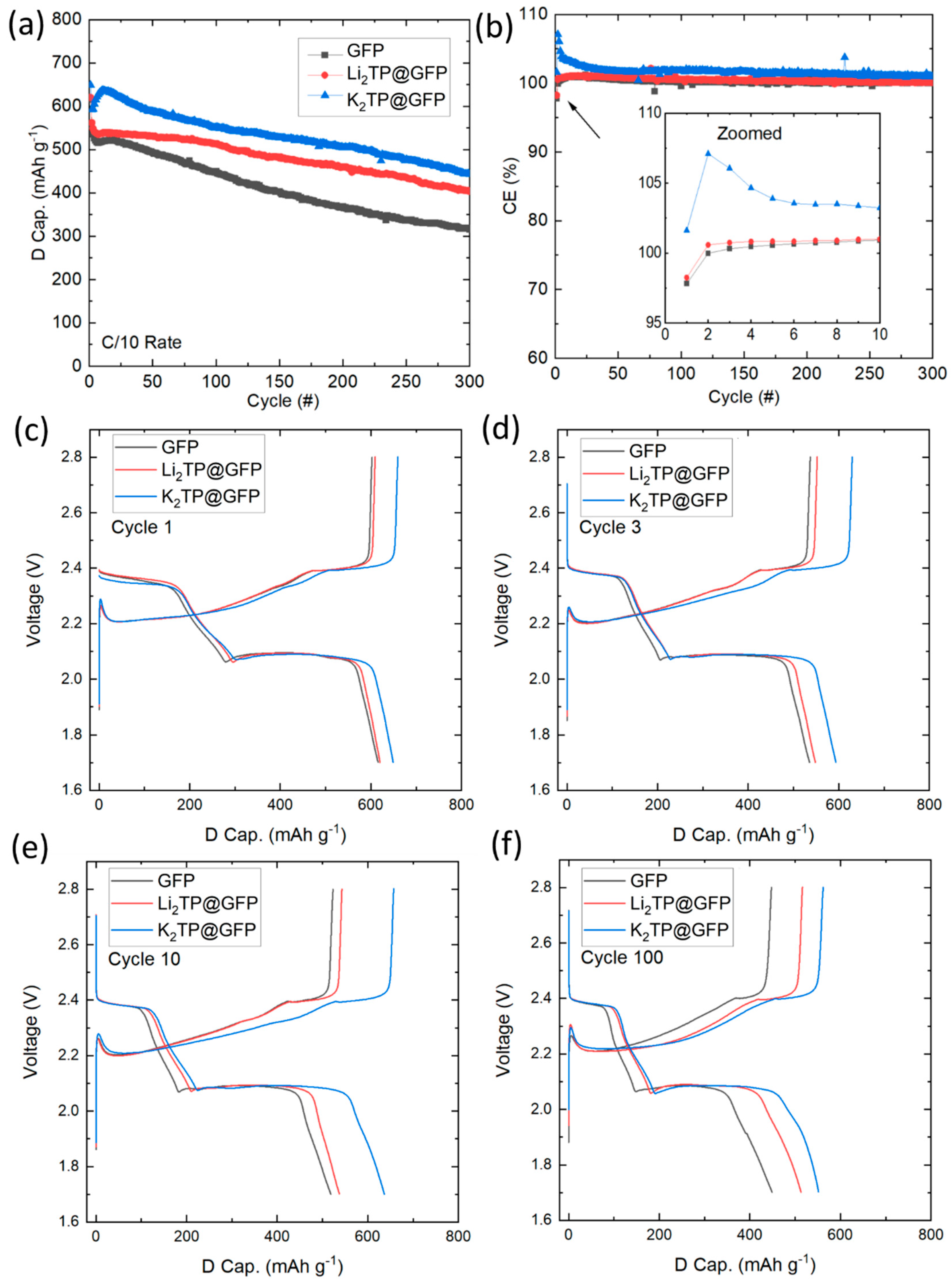
Separators were tested by constant current cycling at C/10 rate in Li||S/C batteries with composite sulfur/carbon cathode at ~1 mg cm−2 S loading with results shown in Figure 4. The cell with K2TP@GFP separator attains the highest capacity both initially and after 300 cycles (Figure 4a). Average capacity fade per cycle for the first 100 cycles is 0.27, 0.18, and 0.15% for GFP, Li2TP@GFP, and K2TP@GFP, respectively. K2TP@GFP also facilitates the highest initial CE, shown in Figure 4b. Initial CEs for GFP, Li2TP@GFP, and K2TP@GFP are 97.8, 98.2, and 101.6%, respectively. Higher CE for K2TP@GFP is maintained during further cycling. At cycle 100, the CEs for each are 99.6, 100.6, and 101.8%, respectively. Since the battery is assembled in the charged state, CE is defined according to Equation (1).
C E = C .   C a p . / ( D .   C a p . )
LSB will spontaneously release LiPSs into the electrolyte from the cathode as the battery self-discharges. Although solubilizing the LiPSs is necessary to enable a complex set of electrochemical reactions, these LiPSs may migrate to the anode and be reduced into insoluble species. They may also remain trapped in the electrolyte and separator or be redeposited back on the cathode during charging [22]. A CE > 100% indicates that sulfur which has spontaneously dissolved into the electrolyte is being redeposited on the cathode during the charge step and undergoing faradaic reactions [45,46]. Due to the slow charge/discharge rate of C/10, this overcharge effect may be magnified [46]. The high CE for K2TP@GFP suggests greater ability to block migration and diffusion of LiPSs to the anode and facilitate redeposition.
Voltage profiles for the initial cycle are shown in Figure 4c. Initial discharge capacities for GFP, Li2TP@GFP, and K2TP@GFP are 615, 620, and 648 mAh g−1, respectively, with K2TP@GFP again providing superior performance. During discharge, three voltage plateaus are seen. The first at ~2.4–2.3 V corresponds to the solid-to-liquid reaction of S8 to form soluble Li2S8. A liquid-to-liquid reaction occurs in the second plateau from ~2.3 to 2.06 V as the polysulfide is further reduced to form Li2S6 and Li2S4. The third voltage plateau is consistent between all cells, occurring at 2.08 V, indicating the coating does not increase impedance or electrolyte polarization. Here, a liquid-to-solid reaction occurs where Li2S4 is converted in competing reactions into passivating Li2S2 and Li2S according to Equations (2) and (3) [8,20,47].
Li 2 S 4 + 2 Li + + 2 e 2 Li 2 S 2
Li 2 S 2 + 2 Li + + 2 e 2 Li 2 S
The voltage subsequently inflects sharply downward as additional resistive Li2S forms. During the charge step, this process is mirrored. Initially, however, there is an activation barrier to oxidize and solubilize electronically insulating Li2S, witnessed by the sharp peak in the voltage [8,20,47]. K2TP@GFP shows comparatively high polarization, giving evidence of a more complete conversion towards Li2S in the discharge plateau. This also increases specific capacity and material utilization and may be enabled by the modified separator maintaining a higher local concentration of Li2S4 in the cathode. Similar trends are observed in cycles 3, 10, and 100 (Figure 4d–f), as well as other studies involving separators modified with polar non-conductive coatings [43,48].
LiPS confinement is further supported by a rise in capacity between cycles 3 and 10 (Figure 4d,e). Sulfur utilization is limited by the availability of conducting surface area. Resistive sulfur may be redistributed over the conducting carbon additive during initial cycles and increase active material utilization [49]. If the dissolved LiPSs instead migrate to the anode and reduce into insoluble Li2S, active material and, thus, capacity is lost. Between cycles 3 and 10, GFP, Li2TP@GFP, and K2TP@GFP cells see, respectively, a −17, −11, and +43 mAh g−1 change in capacity, suggesting K2TP@GFP resists diffusion of LiPS out of the cathode. After sulfur has been distributed in the electrode, capacity fades due to the shuttle effect. Despite greater LiPS generation due to higher material utilization, the LSB with K2TP@GFP separator maintains higher capacity well past cycle 100.
Finally, voltage profiles with modified separators do not reveal any additional peaks or plateaus, indicating that K2TP and Li2TP are electrochemically inactive. Although these materials have been investigated as organic electrode materials, reduction with lithium occurs below the lower cycling voltage limit, and the electronically insulating nature of terephthalates inhibits reactions in the bulk of the separator [34,35,44].

2.4. Post-Cycling Analysis

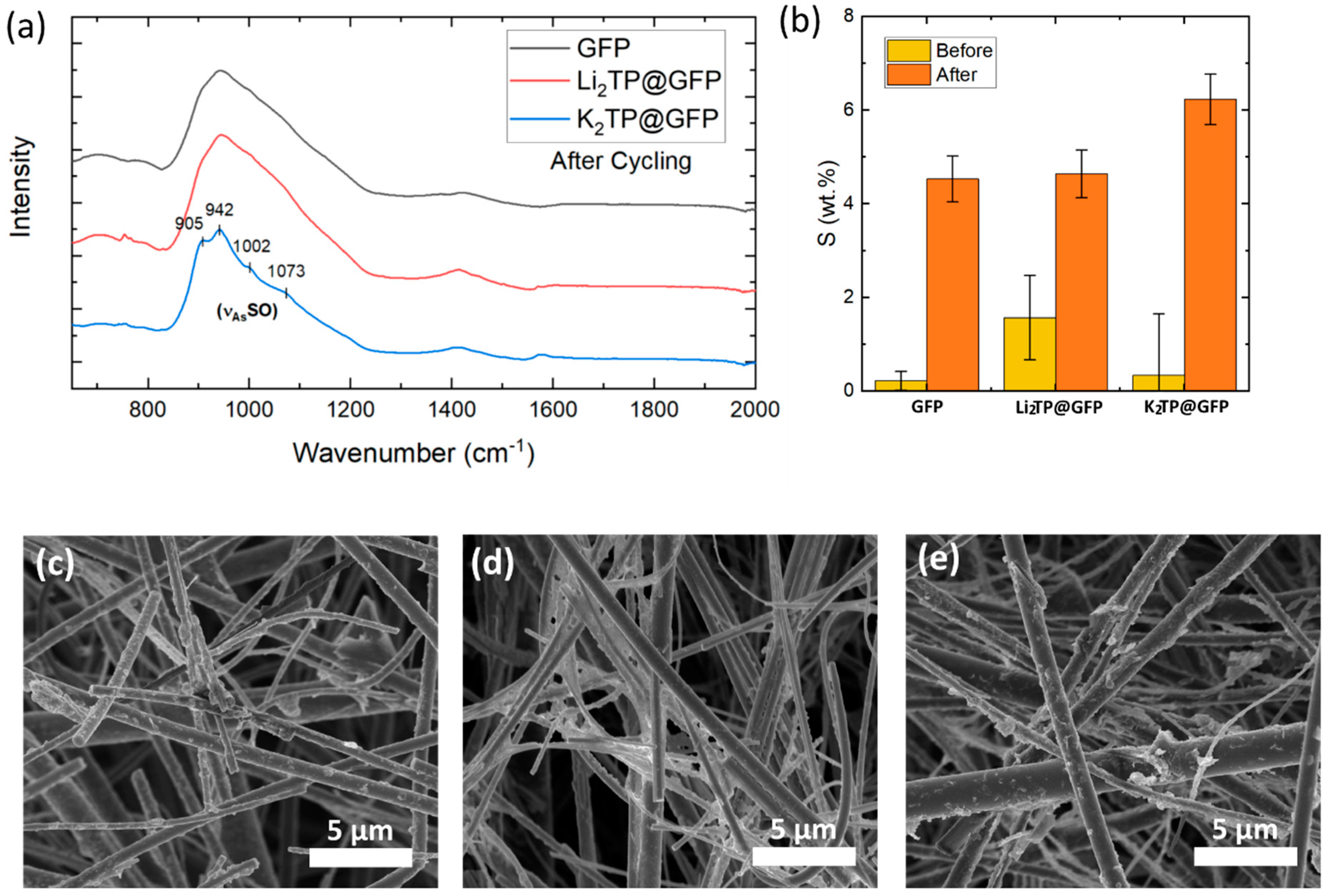
After cycling, the cells were disassembled, and the separators rinsed and dried to remove electrolyte for post-diagnostic characterizations. Figure 5a shows resulting FTIR spectra of the cycled separators. New features can be seen when compared to the pristine separator, particularly for the K2TP separator, which likely correspond to trapped LiPS or those which have deposited on the separator due to disproportionation reactions of soluble species into insoluble ones, as shown in Equation (4) [8,20,47].
L i 2 S n L i 2 S n 1 + 1 / 8 S 8
It is unlikely these peaks come from residual LiNO3 or LiTFSI salt [50,51]. The small peak at 1002 cm−1 may be attributed particularly to the asymmetric stretching of the sulfur-oxygen bond in lithium sulfoxides [52], and others to various sulfur-containing species by process of elimination.
Semi-quantitative EDS measurements allows comparison of the remaining sulfur content (Figure 5b). Unsurprisingly, K2TP@GFP separator shows the highest sulfur content, followed by Li2TP@GFP and untreated GFP. This method, however, is unable to differentiate between soluble polysulfides which have remained trapped in the micropores even after rinsing, or of insoluble compounds which have deposited onto the separator. Regardless, results support the enhanced polysulfide trapping ability of K2TP@GFP.
SEM images of cycled separators in Figure 5c–e reveal the presence of deposited solids, even on the GFP separator. Although modified separators may be able to hinder migration of the LiPSs to the anode and subsequent corrosion and capacity loss, sulfur solids which have deposited by disproportionation onto the insulating separators will still be electrochemically inactive. Future considerations may include utilizing conductive additives which can facilitate the recycling of these solids and allow them to still contribute to the battery capacity.

2.5. Binding Energy Analysis

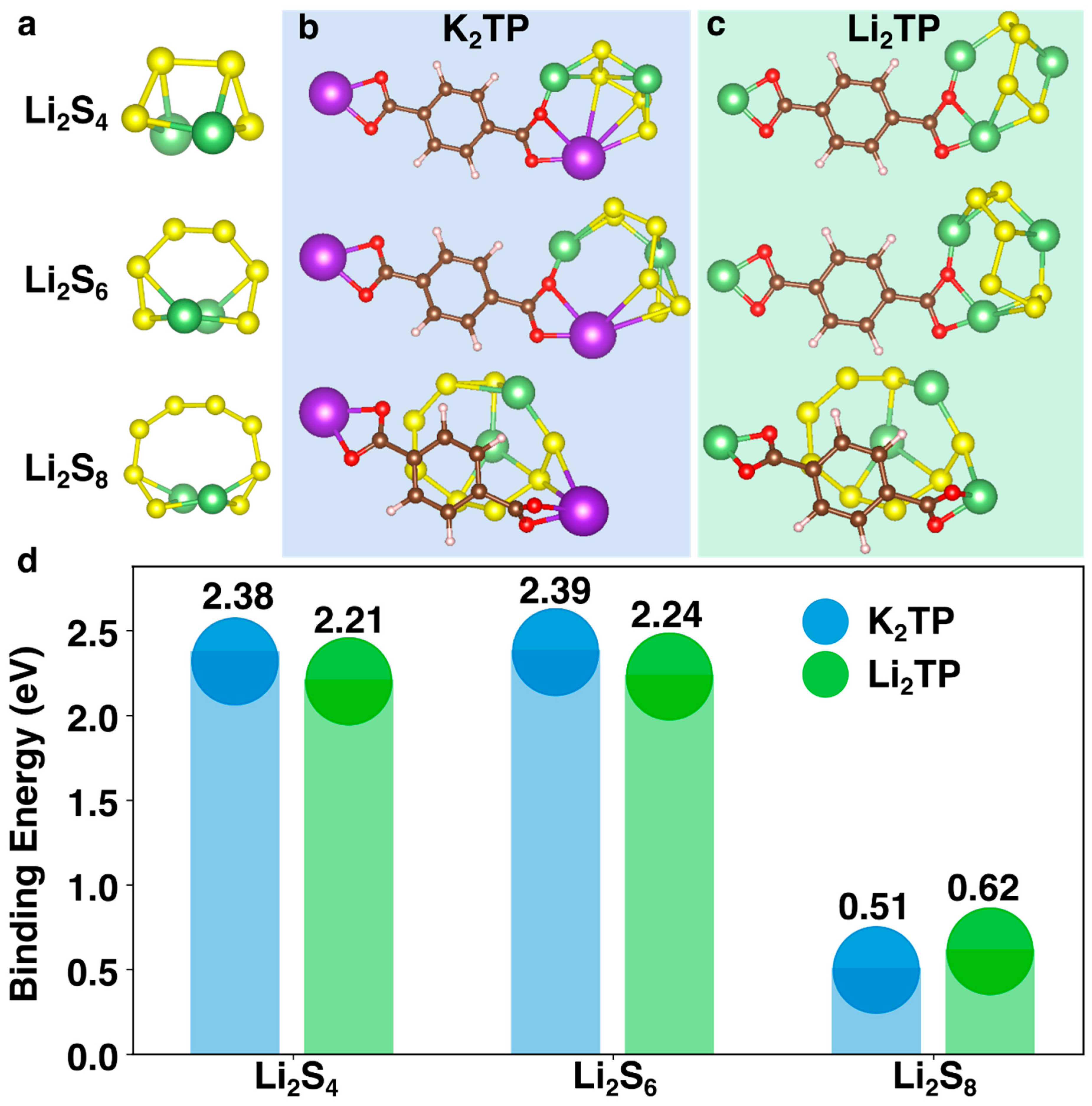
To investigate the molecular basis for the superior trapping ability of K2TP@GFP compared to Li2TP@GFP, the binding energy between terephthalate salts (TPS) and LiPSs was calculated at DFT level using conformational sampling to assess the most stable binding configurations for each LiPS and salt (full details can be found in Section 3). The LiPSs subjected to calculations included Li2S8, Li2S6, and Li2S4, which are soluble in the electrolyte solvents. All the optimized geometries of LiPSs have C2 symmetry and are nonlinear (Figure 6a), which is consistent with previous simulation results [53]. The binding configurations of TPSs on LiPSs can vary drastically depending on the initial position of TPSs, which have infinite possibilities due to the nonlinearity of LiPSs. Conformational searches were conducted on each TPS-LiPS pair and the binding energy was calculated based on the lowest energy conformer using the following Equation (5):
E b i n d = E L i P S + E T P S E a d s o r b e d   s y s t e m
where E denotes the total energy. TPSs showed high binding energy of ~2.3 eV for Li2S4 and Li2S6, compared to ~0.8 eV previously reported for solvents, i.e., DME and DOL, [53] with K2TP having slightly higher binding energy for both cases (Figure 6d). The much higher binding energies (~1.5 eV higher) for both Li2TP and K2TP explains the observed LiPS trapping ability. K2TP has a slightly higher binding energy than Li2TP which agrees with the experimental observations, where K2TP has better performance. However, the ~0.15 eV difference alone may not fully account for the performance difference between K2TP and Li2TP in experiments, suggesting other factors (e.g., pore size…) may also contribute. In addition, binding energies for Li2S8 are low for both TPSs suggesting there may be limited trapping ability of this specific species. Nonetheless, the binding energy analysis still shows that the binding between TPS and LiPSs is an important factor that enables LiPS trapping.

3. Materials and Methods

3.1. Material Syntheses

Depolymerization of PET into dilithium terephthalate (Li2TP) or dipotassium terephthalate (K2TP) was performed according to prior publications [34,35], wherein 2 g of soda bottle PET flakes are combined with either LiOH or KOH (Aldrich, 99.9%), respectively, at a molar ratio of 1:2 in 50 mL of ethylene glycol. The materials are irradiated at 700 W in an ordinary microwave (Microwave Research Applications) four times for one minute, with time in between to allow the solution to cool. The resulting white precipitate was repeatedly rinsed in ethanol and centrifuged, and finally dried at 80 °C under vacuum.

3.2. Material Characterizations

Scanning electron microscope (SEM) images were provided by Nova Nano SEM 200. Fourier-transform infrared (FTIR) spectra were obtained using an Agilent Cary 630 Spectrometer with diamond ATR. Nitrogen gas adsorption/desorption is performed by Quantachrome Instruments NOVA 2200e and analyzed with the Braunauer–Emmett–Teller (BET) method. Quantitative energy dispersive spectroscopy (EDS) is provided by JEOL 600+ benchtop SEM.

3.3. Electrochemical Characterizations

Sulfur/carbon composite was prepared by combining 2 g nanosulfur (SkySpring Nanomaterials, 99.99%, <55 nm) with 1 g graphene nanopowder multilayer flakes (Graphene Supermarket, AO-4) and ball-milling for 30 min at 20 Hz. The resulting composite was combined with Super P conductive carbon (Timcal) and PVDF at weight ratios of 80:5:15, respectively, for 53.3 wt.% sulfur in the total electrode composite. The mixture was combined with approximately 3:1 weight ratio of dry materials to n-methylpyrrolidone solvent and homogenized in a Thinky planetary mixer for 30 min. The resulting slurry was blade-coated onto carbon-coated aluminum foil and dried under vacuum at 45 °C for 12 h. Electrodes were punched into 12 mm cathode disks. Lithium anodes were prepared in an argon glovebox (VAC) with H2O and O2 kept below 0.1 and 0.5 ppm, respectively, by rolling lithium rods (Aldrich, 99.9%) in a polyethylene bag and punched into 14 mm disks. Electrolyte used was 1:1 v/v 1,3 dioxolane (DOL, Aldrich, anhydrous 99.8%) and 1,2-dimethoxyethane (DME, Aldrich, anhydrous 99.5%) with 1 M bis(trifluoromethane)sulfonimide lithium salt (LiTFSI, Aldrich, anhydorus 99.99%) and 0.3 M LiNO3 additive (Alfa Aesar, anhydrous 99%). Cells were assembled with CR2032 coin casings (MTI) and electrolyte-flooded glass fiber paper (GFP, Whatman) separator under argon atmosphere. Electrochemical cycling occurs on MTI BST8-3 Battery Analyzer.

3.4. Separator Characterizations

A 0.25 M Li2S6 solution was prepared in argon atmosphere by stirring stoichiometric quantities of Li2S and S powders in 15 mL of DOL:DME. The polysulfide diffusion test was carried out under argon by placing 2 mL of the polysulfide solution in an autosampler vial with the septum replaced by the separator, and inverted and placed into a larger vial with 5 mL of DOL:DME. After 3 h, 50 μL of the effluent solution was diluted in 200 μl of DOL:DME and absorption analyzed with SpecraMax iD3 Microplate Reader. After cycling, separators were disassembled in an argon glovebox and rinsed three times each for 10 min in 5 mL of DME prior to post-mortem FTIR and SEM analysis to remove residual electrolyte.

3.5. DFT Calculations

Each TPS and LiPS’s geometry was first optimized using ORCA [54] with ω B97X-D3/def2-TVZP density functional theory (DFT) potentials. The initial configuration of each TPS-LiPS pair was constructed ad hoc to avoid overlaps and optimized at the DFT level. The optimized geometries were then subjected to a conformational search using the Conformer-Rotamer Ensemble Sampling Tool (CREST) [55]. The lowest-energy conformer was then used to calculate the binding energy at the DFT level using ORCA.

4. Conclusions

Herein, we have presented a method to address two unrelated but relevant issues, namely, the polysulfide shuttling effect of LSBs and the ever-growing problem of plastic pollution. Plastic PET waste from soda bottles was converted into Li2TP and K2TP terephthalate salts using a fast and facile microwave method, and subsequently coated onto glass fiber separators through a simple solution-coating process. Confirmation of the reactant products and loading are confirmed through FTIR and SEM analyses. Modified separators demonstrate enhanced electrochemical performance of LSBs, attributed to the nanopores which may act as a physical barrier to larger polysulfide anions and strong affinity of charged carboxylate groups for dissolved LiPS, as shown with BET analyses and DFT simulations, respectively. Therefore, K2TP coated separator with the smallest pore size and highest LiPS affinity performs the best, enhancing initial capacity in long-cycling studies at C/10 constant current rate by 5.4% to 648 mAh g−1, and capacity retention after 100 cycles by 23% to 551 mAh g−1. LiPS blocking ability is further supported by inhibited diffusion through the coated separators in ex situ analysis. Post-mortem analyses of cycled separators reveal the presence of inactive sulfur on the separators. Future studies may investigate ways to facilitate recycling of disproportionated sulfur to further enhance capacity retention, such as including conductive additives or utilizing alkali terephthalates as an active material coating. Systematic studies seeking to decouple contributions from physical blocking, molecular interactions, and selective cation transport may also be warranted.

Author Contributions

Conceptualization, D.A.G. and S.G.; methodology, D.A.G., S.G., and Z.-Y.L.; software, Z.-Y.L.; validation, D.A.G. and Z.-Y.L.; formal analysis, D.A.G. and Z.-Y.L.; investigation, D.A.G. and V.G.P.; resources, V.G.P.; data curation, D.A.G. and V.G.P.; writing—original draft preparation, D.A.G. and Z.-Y.L.; writing—review and editing, D.A.G., Z.-Y.L., B.M.S., and V.G.P.; visualization, D.A.G. and Z.-Y.L.; supervision, B.M.S. and V.G.P.; project administration, V.G.P.; funding acquisition, V.G.P. All authors have read and agreed to the published version of the manuscript.

Funding

Authors thanks to National Science Foundation with grant number NSF-21057822-02 for supporting presented work.

Institutional Review Board Statement

Not applicable.

Informed Consent Statement

Not applicable.

Data Availability Statement

The data that support the plots within this paper and other finding of this study are available from the corresponding authors on reasonable request.

Acknowledgments

The authors express thanks to the lab of Julie Liu of Davidson School of Chemical Engineering for providing equipment access and training for UV spectroscopy, as well as David Olawale and Harsha Rao for scientific discussions.

Conflicts of Interest

The authors declare no conflict of interest.

References

  1. Why Big Battery Phones Do Not Guarantee More Screen on Time? Hidden Facts, (n.d.). Available online: https://gadgetstouse.com/blog/2021/01/21/why-big-battery-phones-do-not-guarantee-more-screen-on-time-hidden-facts/ (accessed on 30 August 2022).
  2. Lithium Metal Batteries Can Power Drones for Longer, (n.d.). Available online: https://www.popularmechanics.com/flight/drones/a27155551/battery-boeing/ (accessed on 30 August 2022).
  3. Liu, Y.; Liu, S.; Li, G.; Gao, X. Strategy of Enhancing the Volumetric Energy Density for Lithium–Sulfur Batteries. Adv. Mater. 2021, 33, 2003955. [Google Scholar] [CrossRef] [PubMed]
  4. Etacheri, V.; Marom, R.; Elazari, R.; Salitra, G.; Aurbach, D. Challenges in the development of advanced Li-ion batteries: A review. Energy Environ. Sci. 2011, 4, 3243–3262. [Google Scholar] [CrossRef]
  5. Cabana, J.; Monconduit, L.; Larcher, D.; Palacín, M.R. Beyond Intercalation-Based Li-Ion Batteries: The State of the Art and Challenges of Electrode Materials Reacting Through Conversion Reactions. Adv. Mater. 2010, 22, 170–192. [Google Scholar] [CrossRef] [PubMed]
  6. Yang, L.; Li, Q.; Wang, Y.; Chen, Y.; Guo, X.; Wu, Z.; Chen, G.; Zhong, B.; Xiang, W.; Zhong, Y. A review of cathode materials in lithium-sulfur batteries. Ionics 2020, 26, 5299–5318. [Google Scholar] [CrossRef]
  7. Huang, Y.; Duan, J.; Zheng, X.; Wen, J.; Dai, Y.; Wang, Z.; Luo, W.; Huang, Y. Lithium Metal-Based Composite: An Emerging Material for Next-Generation Batteries. Matter 2020, 3, 1009–1030. [Google Scholar] [CrossRef]
  8. Rana, M.; Ahad, S.A.; Li, M.; Luo, B.; Wang, L.; Gentle, I.; Knibbe, R. Review on areal capacities and long-term cycling performances of lithium sulfur battery at high sulfur loading. Energy Storage Mater. 2019, 18, 289–310. [Google Scholar] [CrossRef]
  9. Pan, H.; Cheng, Z.; He, P.; Zhou, H. A Review of Solid-State Lithium–Sulfur Battery: Ion Transport and Polysulfide Chemistry. Energy Fuels 2020, 34, 11942–11961. [Google Scholar] [CrossRef]
  10. Wild, M.; O’Neill, L.; Zhang, T.; Purkayastha, R.; Minton, G.; Marinescu, M.; Offer, G.J. Lithium sulfur batteries, a mechanistic review. Energy Environ. Sci. 2015, 8, 3477–3494. [Google Scholar] [CrossRef]
  11. Hu, Y.; Chen, W.; Lei, T.; Jiao, Y.; Huang, J.; Hu, A.; Gong, C.; Yan, C.; Wang, X.; Xiong, J. Strategies toward High-Loading Lithium–Sulfur Battery. Adv. Energy Mater. 2020, 10, 2000082. [Google Scholar] [CrossRef]
  12. Kim, P.J.H.; Kim, K.; Pol, V.G. Towards highly stable lithium sulfur batteries: Surface functionalization of carbon nanotube scaffolds. Carbon 2018, 131, 175–183. [Google Scholar] [CrossRef]
  13. Dysart, A.D.; Burgos, J.C.; Mistry, A.; Chen, C.-F.; Liu, Z.; Hong, C.N.; Balbuena, P.B.; Mukherjee, P.P.; Pol, V.G. Towards Next Generation Lithium-Sulfur Batteries: Non-Conventional Carbon Compartments/Sulfur Electrodes and Multi-Scale Analysis. J. Electrochem. Soc. 2016, 163, A730–A741. [Google Scholar] [CrossRef]
  14. Kim, P.J.; Fontecha, H.D.; Kim, K.; Pol, V.G. Toward High-Performance Lithium–Sulfur Batteries: Upcycling of LDPE Plastic into Sulfonated Carbon Scaffold via Microwave-Promoted Sulfonation. ACS Appl. Mater. Interfaces 2018, 10, 14827–14834. [Google Scholar] [CrossRef]
  15. Hu, C.; Chen, H.; Shen, Y.; Lu, D.; Zhao, Y.; Lu, A.-H.; Wu, X.; Lu, W.; Chen, L. In situ wrapping of the cathode material in lithium-sulfur batteries. Nat. Commun. 2017, 8, 479. [Google Scholar] [CrossRef] [Green Version]
  16. Lee, J.; Choi, W. Surface Modification of Sulfur Cathodes with PEDOT:PSS Conducting Polymer in Lithium-Sulfur Batteries. J. Electrochem. Soc. 2015, 162, A935–A939. [Google Scholar] [CrossRef]
  17. Kim, K.; Kim, P.J.H.; Youngblood, J.P.; Pol, V.G. Surface Functionalization of Carbon Architecture with Nano-MnO2 for Effective Polysulfide Confinement in Lithium–Sulfur Batteries. ChemSusChem 2018, 11, 2375–2381. [Google Scholar] [CrossRef] [PubMed]
  18. Wu, P.; Sun, M.-H.; Yu, Y.; Peng, Z.; Bulbula, S.T.; Li, Y.; Chen, L.-H.; Su, B.-L. Physical and chemical dual-confinement of polysulfides within hierarchically meso-microporous nitrogen-doped carbon nanocages for advanced Li–S batteries. RSC Adv. 2017, 7, 42627–42633. [Google Scholar] [CrossRef] [Green Version]
  19. Yuan, H.; Huang, J.-Q.; Peng, H.-J.; Titirici, M.-M.; Xiang, R.; Chen, R.-J.; Liu, Q.-B.; Zhang, Q. A Review of Functional Binders in Lithium-Sulfur Batteries. Adv. Energy Mater. 2018, 8, 1802107. [Google Scholar] [CrossRef]
  20. Liu, Y.; Elias, Y.; Meng, J.; Aurbach, D.; Zou, R.; Xia, D.; Pang, Q. Electrolyte solutions design for lithium-sulfur batteries. Joule 2021, 5, 2323–2364. [Google Scholar] [CrossRef]
  21. Wang, X.; Tan, Y.; Shen, G.; Zhang, S. Recent progress in fluorinated electrolytes for improving the performance of Li–S batteries. J. Energy Chem. 2020, 41, 149–170. [Google Scholar] [CrossRef] [Green Version]
  22. Li, G.R.; Li, Z.; Zhang, B.; Lin, Z. Developments of electrolyte systems for lithium–sulfur batteries: A review. Front. Energy Res. 2015, 3, 5. [Google Scholar] [CrossRef]
  23. Weng, W.; Pol, V.G.; Amine, K. Ultrasound Assisted Design of Sulfur/Carbon Cathodes with Partially Fluorinated Ether Electrolytes for Highly Efficient Li/S Batteries. Adv. Mater. 2013, 25, 1608–1615. [Google Scholar] [CrossRef] [PubMed]
  24. Yang, D.; Xiong, X.; Zhu, Y.; Chen, Y.; Fu, L.; Zhang, Y.; Wu, Y. Modifications of Separators for Li–S Batteries with Improved Electrochemical Performance. Russ. J. Electrochem. 2020, 56, 365–377. [Google Scholar] [CrossRef]
  25. Zhao, Q.; Hao, Z.; Tang, J.; Xu, X.; Liu, J.; Jin, Y.; Zhang, Q.; Wang, H. Cation-Selective Separators for Addressing the Lithium–Sulfur Battery Challenges. ChemSusChem 2021, 14, 792–807. [Google Scholar] [CrossRef] [PubMed]
  26. Wei, Z.; Ren, Y.; Sokolowski, J.; Zhu, X.; Wu, G. Mechanistic understanding of the role separators playing in advanced lithium-sulfur batteries. InfoMat 2020, 2, 483–508. [Google Scholar] [CrossRef] [Green Version]
  27. Zhao, Q.; Wang, R.; Wen, J.; Hu, X.; Li, Z.; Li, M.; Pan, F.; Xu, C. Separator engineering toward practical Li-S batteries: Targeted electrocatalytic sulfur conversion, lithium plating regulation, and thermal tolerance. Nano Energy 2022, 95, 106982. [Google Scholar] [CrossRef]
  28. Kim, H.-S.; Kang, H.-J.; Lim, H.; Hwang, H.J.; Park, J.-W.; Lee, T.-G.; Cho, S.Y.; Jang, S.G.; Jun, Y.-S. Boron Nitride Nanotube-Based Separator for High-Performance Lithium-Sulfur Batteries. Nanomaterials 2021, 12, 11. [Google Scholar] [CrossRef]
  29. Song, X.; Wang, S.; Chen, G.; Gao, T.; Bao, Y.; Ding, L.-X.; Wang, H. Fe-N-doped carbon nanofiber and graphene modified separator for lithium-sulfur batteries. Chem. Eng. J. 2018, 333, 564–571. [Google Scholar] [CrossRef]
  30. Hu, S.; Yi, M.; Huang, X.; Wu, D.; Lu, B.; Wang, T.; Li, N.; Zhu, Z.; Liu, X.; Zhang, J. Cobalt-doped porphyrin-based porous organic polymer-modified separator for high-performance lithium–sulfur batteries. J. Mater. Chem. A 2021, 9, 2792–2805. [Google Scholar] [CrossRef]
  31. CPaniagua-Vásquez, I.; Zuluaga-Gómez, C.C.; Chacón-Vargas, S.; Calvo, A.L.; Sáenz-Arce, G.; Katiyar, R.S.; Saavedra-Arias, J.J. High Specific Capacity of Lithium–Sulfur Batteries with Carbon Black/Chitosan-and Carbon Black/Polyvinylidene Fluoride-Coated Separators. Energies 2022, 15, 2183. [Google Scholar] [CrossRef]
  32. Al-Salem, S.M.; Lettieri, P.; Baeyens, J. Recycling and recovery routes of plastic solid waste (PSW): A review. Waste Manag. 2009, 29, 2625–2643. [Google Scholar] [CrossRef]
  33. Goodship, V. Plastic Recycling. Sci. Prog. 2007, 90, 245–268. [Google Scholar] [CrossRef] [PubMed]
  34. Ghosh, S.; Makeev, M.A.; Qi, Z.; Wang, H.; Rajput, N.N.; Martha, S.K.; Pol, V.G. Rapid Upcycling of Waste Polyethylene Terephthalate to Energy Storing Disodium Terephthalate Flowers with DFT Calculations. ACS Sustain. Chem. Eng. 2020, 8, 6252–6262. [Google Scholar] [CrossRef]
  35. Ghosh, S.; Makeev, M.A.; Macaggi, M.L.; Qi, Z.; Wang, H.; Rajput, N.N.; Martha, S.K.; Pol, V.G. Dipotassium terephthalate as promising potassium storing anode with DFT calculations. Mater. Today Energy 2020, 17, 100454. [Google Scholar] [CrossRef]
  36. Ioakeimidis, C.; Fotopoulou, K.N.; Karapanagioti, H.K.; Geraga, M.; Zeri, C.; Papathanassiou, E.; Galgani, F.; Papatheodorou, G. The degradation potential of PET bottles in the marine environment: An ATR-FTIR based approach. Sci. Rep. 2016, 6, 23501. [Google Scholar] [CrossRef] [PubMed] [Green Version]
  37. Varghese, H.T.; Panicker, C.Y.; Philip, D.; Sreevalsan, K.; Anithakumary, V. IR, Raman and SERS spectra of disodium terephthalate. Spectrochim. Acta Part A Mol. Biomol. Spectrosc. 2007, 68, 817–822. [Google Scholar] [CrossRef] [PubMed]
  38. Babar, S.; Lekakou, C. Molecular modeling of electrolyte and polysulfide ions for lithium-sulfur batteries. Ionics 2021, 27, 635–642. [Google Scholar] [CrossRef]
  39. Cao, Y.; Wu, C.; Wang, W.; Li, Y.; You, J.; Zhang, B.; Zou, J.; Abuelgasim, S.; Zhu, T.; Wu, J.; et al. Modification of lithium sulfur batteries by sieving effect: Long term investigation of carbon molecular sieve. J. Energy Storage 2022, 54, 105228. [Google Scholar] [CrossRef]
  40. Bai, S.; Liu, X.; Zhu, K.; Wu, S.; Zhou, H. Metal–organic framework-based separator for lithium–sulfur batteries. Nat. Energy 2016, 1, 16094. [Google Scholar] [CrossRef]
  41. FTIR Measurements of SiO2 Glass Prepared by Sol-Gel Technique. Chem. Sci. Trans. 2014, 3, 1064–1066. [CrossRef] [Green Version]
  42. Jiang, K.; Gao, S.; Wang, R.; Jiang, M.; Han, J.; Gu, T.; Liu, M.; Cheng, S.; Wang, K. Lithium Sulfonate/Carboxylate-Anchored Polyvinyl Alcohol Separators for Lithium Sulfur Batteries. ACS Appl. Mater. Interfaces 2018, 10, 18310–18315. [Google Scholar] [CrossRef]
  43. Conder, J.; Urbonaite, S.; Streich, D.; Novák, P.; Gubler, L. Taming the polysulphide shuttle in Li–S batteries by plasma-induced asymmetric functionalisation of the separator. RSC Adv. 2015, 5, 79654–79660. [Google Scholar] [CrossRef]
  44. Kumaresan, L.; Kasiviswanathan, K.; Kirubakaran, K.P.; Priyadarshini, M.; Mathiyalagan, K.; Senthil, C.; Lee, C.W.; Vediappan, K. Band-Gap Tuned Dilithium Terephthalate from Environmentally Hazardous Material for Sustainable Lithium Storage Systems with DFT Modelling. ChemistrySelect 2022, 7, e202200527. [Google Scholar] [CrossRef]
  45. Lee, Y.; Choi, N.; Park, J.; Park, J. Electrochemical Performance of Lithium/Sulfur Batteries with Protected Li Anodes. J. Power Sources 2003, 119–121, 964–972. [Google Scholar] [CrossRef]
  46. Sun, M.; Wang, X.; Wang, J.; Yang, H.; Wang, L.; Liu, T. Assessment on the Self-Discharge Behavior of Lithium–Sulfur Batteries with LiNO3-Possessing Electrolytes. ACS Appl. Mater. Interfaces 2018, 10, 35175–35183. [Google Scholar] [CrossRef]
  47. Zhang, S.S. Liquid electrolyte lithium/sulfur battery: Fundamental chemistry, problems, and solutions. J. Power Sources 2013, 231, 153–162. [Google Scholar] [CrossRef]
  48. Li, J.; Huang, Y.; Zhang, S.; Jia, W.; Wang, X.; Guo, Y.; Jia, D.; Wang, L. Decoration of Silica Nanoparticles on Polypropylene Separator for Lithium–Sulfur Batteries. ACS Appl. Mater. Interfaces 2017, 9, 7499–7504. [Google Scholar] [CrossRef]
  49. Liu, J.; Zheng, Y. Dissolution and Reprecipitation of Sulfur on Carbon Surface. J. Electron. Mater. 2022, 51, 2926–2932. [Google Scholar] [CrossRef]
  50. Kam, W.; Liew, C.-W.; Lim, J.Y.; Ramesh, S. Electrical, structural, and thermal studies of antimony trioxide-doped poly(acrylic acid)-based composite polymer electrolytes. Ionics 2013, 20, 665–674. [Google Scholar] [CrossRef]
  51. Patil, V.S.; Vithya, K.; Premalatha, M.; Sundaresan, B. FTIR Studies on PMMA-LiNO3 Polymer Electrolyte. Macromol. Symp. 2019, 387, 1800177. [Google Scholar] [CrossRef]
  52. Diao, Y.; Xie, K.; Xiong, S.; Hong, X. Insights into Li-S Battery Cathode Capacity Fading Mechanisms: Irreversible Oxidation of Active Mass during Cycling. J. Electrochem. Soc. 2012, 159, 1816–1821. [Google Scholar] [CrossRef]
  53. Lin, H.; Yang, D.-D.; Lou, N.; Wang, A.-L.; Zhu, S.-G.; Li, H.-Z. Defect engineering of black phosphorene towards an enhanced polysulfide host and catalyst for lithium-sulfur batteries: A first principles study. J. Appl. Phys. 2019, 125, 094303. [Google Scholar] [CrossRef]
  54. Neese, F. The ORCA program system. Wiley Interdiscip. Rev. Comput. Mol. Sci. 2012, 2, 73–78. [Google Scholar] [CrossRef]
  55. Pracht, P.; Bohle, F.; Grimme, S. Automated exploration of the low-energy chemical space with fast quantum chemical methods. Phys. Chem. Chem. Phys. 2020, 22, 7169–7192. [Google Scholar] [CrossRef] [PubMed]
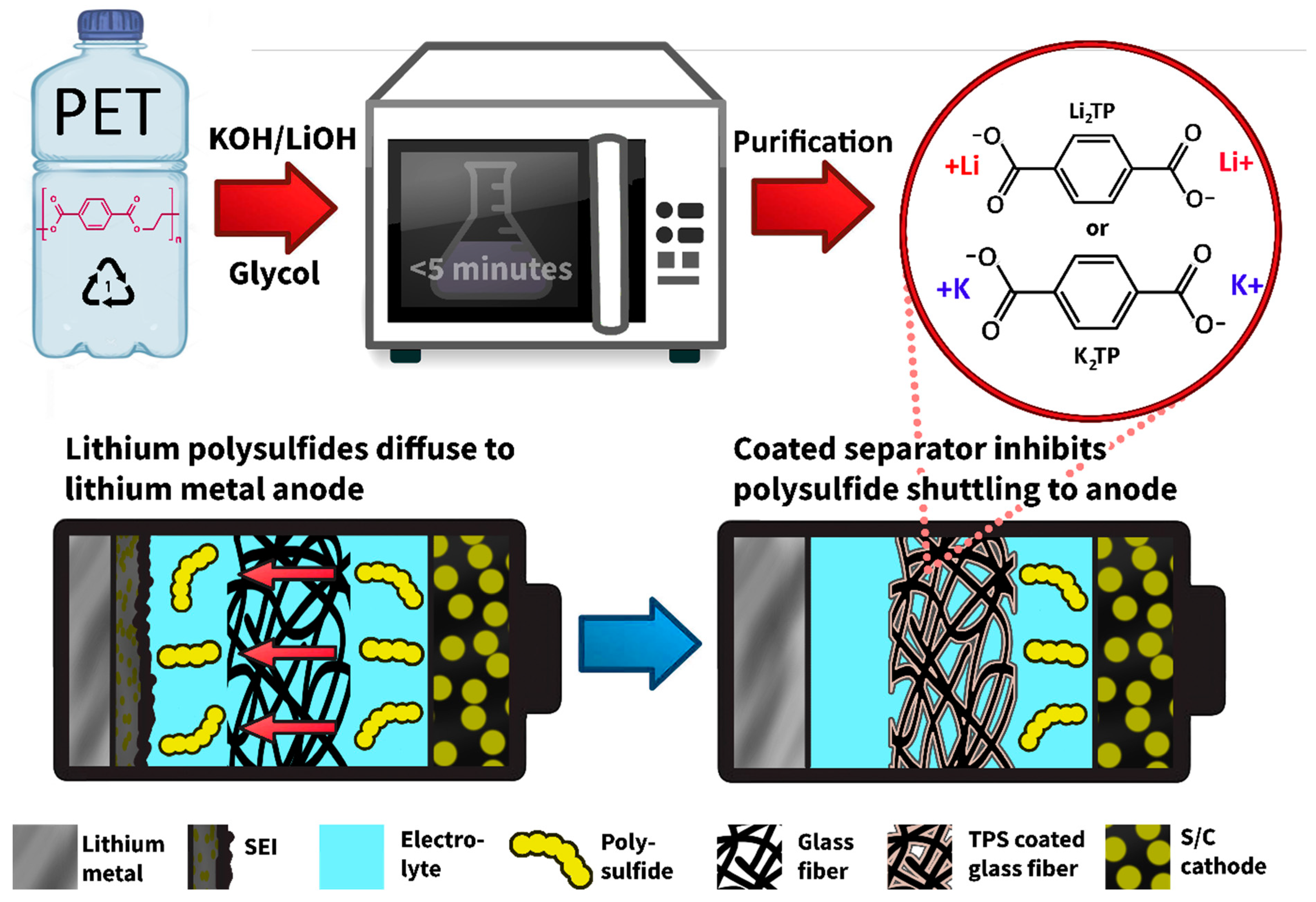
Figure 1. Pictorial of synthetic process of TPS from waste PET and LiPS blocking mechanism of the modified separator.
Batteries 08 00253 g001
Figure 2. Characterizations of starting materials including (a) FTIR spectra of the PET bottle flakes, Li2TP, and K2TP, as well as SEM images of the synthesized (b) Li2TP and (c) K2TP powders. Chara-terization also includes nitrogen adsorption/desorption isotherms with calculated BET surface area for (d) Li2TP and (e) K2TP, as well as (f) calculated pore size distributions for both TPS.
Batteries 08 00253 g002
Figure 3. Characterizations of separators, including (a) FTIR spectra of modified and unmodified GFP, as well as SEM images of (b) GFP, (c) Li2TP@GFP, and (d) K2TP@GFP. (e) Absorbance spectra of DOL:DME solution after 3 h against 0.1 M Li2S6 solution in separator diffusion test.
Batteries 08 00253 g003
Figure 4. (a) C/10 cycling and (b) CE of LSBs with modified and modified separators, as well as select voltage profiles from cycles (c) 1, (d) 3, (e) 10, and (f) 100.
Batteries 08 00253 g004
Figure 5. Post-mortem analysis of modified and unmodified separators cycled in LSBs including (a) FTIR, (b) EDS sulfur quantitative analysis, and SEM of (c) GFP, (d) Li2TP@GFP, and (e) K2TP@GFP.
Batteries 08 00253 g005
Figure 6. Binding energy between Li2TP and K2TP, and Li2S4, Li2S6, and Li2S8. (a) optimized geometry of Li2S4, Li2S6, and Li2S8; binding configurations for (b) K2TP-LiPSs and (c) Li2TP-LiPSs; (d) summary of binding energy for each TPS-LiPS pair. The atoms were colored as: Li, green; K, purple; S, yellow; C, brown; O, red.
Batteries 08 00253 g006
Publisher’s Note: MDPI stays neutral with regard to jurisdictional claims in published maps and institutional affiliations.