Abstract
Common issues aqueous-based vanadium redox flow batteries (VRFBs) face include low cell voltage due to water electrolysis side reactions and highly corrosive and environmentally unfriendly electrolytes (3 to 5 M sulfuric acid). Therefore, this investigation looks into the comparison of a highly conductive ionic liquid with a well-studied deep eutectic solvent (DES) as electrolytes for non-aqueous VRFBs. The latter solvent gives 50% higher efficiency and capacity utilization than the former. These figures of merit increase by 10% when nitrogen-doped graphene (N-G)-modified carbon papers, via a one-step binder-free electrophoretic deposition process, are used as electrodes. X-ray computed tomography confirms the enhancement of electrochemical surface area of the carbon electrodes due to N-G while electrochemical impedance spectra show the effect of its higher conductivity on improving RFB performance. Finally, potential strategies for the scaling-up of DES-based VRFBs using a simple economical model are also briefly discussed. From this study, it is deduced that more investigations on applying DESs as non-aqueous electrolytes to replace the commonly used acetonitrile may be a positive step forward because DESs are not only cheaper but also safer to handle, far less toxic, non-flammable, and less volatile than acetonitrile.
1. Introduction
The aqueous-based all-vanadium redox flow battery (VRFB) is one of the most investigated and commercially available grid-scale electrochemical energy storage devices for potential renewable energy applications [1,2,3,4,5,6,7]. Despite its myriad of advantages, which include the use of a single element in both half-cells, thereby eliminating cross-contamination problems [8], one of its drawbacks involves low energy and power densities that limit its potential commercial uptake in areas such as transportation or energy storage for home appliances [9]. To address this issue, several researchers have considered non-aqueous solvents such as acetonitrile [10] or combinations thereof with other protic or non-protic solvents by applying vanadium acetylacetonate (Vacac) as a model compound [11,12,13]. The main idea behind the application of such non-aqueous solvents was to eliminate the practical voltage limitations afforded by aqueous systems and thereby allow batteries to be developed with potentially higher power densities [9]. Despite considering important performance metrics for judicious solvent selection, such as Vacac redox reaction rate, solubility, and electrolyte conductivity, other crucial aspects such as price, handling safety, volatility, and toxicity also need accounting for [11].
Therefore, ionic liquids (ILs) and their deep eutectic solvent (DES) analogs as electrolytic media have also been considered as a replacement for acetonitrile-based non-aqueous vanadium redox flow batteries (VRFBs) [14,15,16]. In general, ILs are less corrosive than aqueous-based sulfuric acid and less toxic than acetonitrile [17]. Thus, taking purely solubility as a criterion, some workers showed via simulations that an IL consisting of an imidazolium cation in combination with bis(trifluoromethane)sulfonimide anions would be ideal for Vacac applications [18]. However, other factors need to be evaluated for the ILs and DESs such as conductivity, viscosity, electrochemical window of operation, and price amongst others.
DESs have been studied recently for several redox flow battery (RFB) applications [19,20,21] owing to their similar nature to the chloride-rich ILs, as well as their biodegradability, non-toxicity, and lower costs than most ILs [15,22,23]. Most of these RFBs use standard carbon-based electrodes without any sort of physicochemical modifications [24]. In this regard, engineering of the carbon electrode structure for enhancing RFB performance is significant with respect to the reduction in stack costs. The important aspects for a good electrode are dependent on the interaction of its microstructure, surface chemistry, and performance with: (1) Solvent wetting properties; (2) pressure drop; (3) electrochemical surface area (ECSA); (4) tortuosity; and (5) mechanical properties under compression [25,26]. To effect such electrode materials, researchers have modified them by means of carbon nanotubes or graphene [27], but applications have remained limited to aqueous-based VRFBs [28,29,30]. Recently, electrophoretic deposition (EPD) was applied to modify commercially available carbon papers with reduced graphene oxide to enhance VRFB [31] and hydrogen/vanadium fuel cells [32]. Considering the fact that the literature on DES-based RFBs has not reported any such investigations with electrode modification by means of EPD, this work was conducted to evaluate how the cell performance of a standard DES electrolyte would change when employing carbon electrodes spiked with graphene.
In particular, nitrogen-doped graphene (N-G) has worked tremendously well as an electro-catalyst or electrochemical surface area (ECSA) enhancer for aqueous-organic systems [33,34,35], but its use in IL media for VRFBs appears limited. As nitrogen is more electronegative than carbon, it can donate an electron pair to its neighboring carbon atoms as a consequence of N-doping, which, in turn, enhances the electronic conductivity of the carbonaceous electrode [36]. As a consequence, it was considered important to investigate the performance of N-G via EPD on SGL 10AA carbon paper (N-G/SGL) as potential electrode materials for a non-aqueous Vacac-based flow battery operating using a standard DES electrolyte. The DES (also known as ethaline) was chosen based upon its previous investigation in an H-type glass cell [37], due to its good electrolytic properties [38] and also because of its efficient performance in an all-copper RFB [39]. The DES-based RFB in the present work gave higher efficiencies and better electrolyte utilization when N-G/SGL electrodes were employed. Based upon this, future studies are envisaged in terms of electrolyte and membrane-electrode-assembly (MEA) optimization to scale-up such DES-based flow batteries for potential commercial applications.
2. Experimental
2.1. Chemicals
The ionic liquid, 1-ethyl-methylimidazolium tricyanomethanide (>98% purity), was sourced from IOLITEC, Germany. Vanadium (III) acetylacetonate (97% purity), hexamethylenetetramine (HMTA), Molecular sieve 4A, 1-ethyl-1-methylpyrrolidinium bis(trifluoromethylsulfonyl)imide (99% purity), N,N-dimethylformamide (99.8%), and tetraethylammonium tetrafluoroborate (TEABF4, 99%) were purchased from Sigma-Aldrich. Choline chloride (99%), acetone (reagent grade), potassium chloride standard solution for conductivity measurements, ethanol (reagent grade), acetonitrile (99%), 5 M hydrochloric acid, and ethylene glycol (99.8%) were purchased from Merck. All chemicals were used as received, but the electrolytes were dried by means of the molecular sieves inside an argon (Ar)-filled glove box prior to electrochemical investigations. The ethaline DES was prepared using ethylene glycol and choline chloride via a standard thermal stirring procedure as reported in our earlier work [38].
2.2. Materials
The glassy carbon working electrode (GC), platinum counter electrode, and Ag/Ag+ reference electrode (with a porous frit to allow ion exchange) were sourced from BASi (EC-Lab Ltd., Glossop, UK) along with the 10 mL three-electrode cell. The 3 mm (inner diameter) GC was polished with a PK-3 polishing kit also sourced from EC-Lab (BASi) and washed with acetone and the test solution prior to electrochemical experiments. A similar procedure was followed when using a thin strip of carbon paper (0.001 cm2 geometric area—SGL 10AA gas diffusion electrode sourced from SGL Carbon) as the working electrode in place of the GC. This carbon paper (CP) was soaked in the IL or DES solution for at least 24 h prior to performing any cyclic voltammetry (CV) experiments. Additionally, one CP was further pre-treated by soaking it in 1-ethyl-1-methylpyrrolidinium bis(trifluoromethylsulfonyl)imide for a few days inside an Ar-filled glove box prior to performing CVs. This procedure ensured that the CP was exposed to an IL containing an electron donor on its cation as a functional group. From the literature, this IL was found to enhance the electrochemical stability of Vacac [40]. The CV of this pre-treated CP was compared to that of the untreated one. All experiments were conducted inside the Ar-filled glove box. As-received V(acac)3 and ionic liquid, as well as the synthesized DES [38], were used without further purification but were dried using molecular sieves.
2.3. Nitrogen Doping of Graphene
Nitrogen-doped graphene (N-G) was obtained as reported in the literature [41]. In brief, 3 g of HMTA, graphene powder (4 g, obtained from collaborators in Manchester University), and 3 mL of de-ionized water were combined within a 20 mL stainless steel autoclave. The autoclave was assembled inside an electric box furnace, heated at a rate of 10 °C min−1 to 500 °C, and maintained at this temperature for 22 h. After the thermal treatment, the autoclave was allowed to cool down to room temperature [41]. The precipitate was filtered, and rinsed thoroughly with de-ionized water, ethanol, and 5 M hydrochloric acid a few times prior to vacuum drying at 50 °C for 3 h.
2.4. Physicochemical Properties
The solubility of vanadium acetylacetonate in the IL or DES was determined by means of UV/vis spectra by dissolving different concentrations of the solute. Excess amounts of the solute were added into the IL or DES, and the solutions were centrifuged. A Shimadzu UV-vis 2400PC spectrophotometer (Shimadzu, Milton Keynes, UK) was employed for UV-visible absorption spectra measurements. IL or DES viscosity was determined by means of a standard Brookfield instrument. A DZS-708 multi-parameter analyzer (INESA Scientific Instrument Co., Ltd., Shanghai, China) was used to measure the electrolyte conductivities. This instrument was calibrated by means of a 0.001 M KCl standard solution. Temperature was maintained by means of a water bath.
2.5. Electrophoretic Deposition (EPD)
The EPD procedure followed here was exactly the same as that reported in our previous work [42]. In brief, a horizontal EPD reactor was used to deposit 0.1 g L−1 of N-G (dispersed within DMF) on CP samples for 30 min at 300 V (TTi provided the power supply), as shown in Figure 1a [42]. Figure 1b shows the EPD process in which the N-G particles deposit on the top working electrode (CP). Deposits were performed for one side of the carbon paper sample only, as double-sided deposits resulted in poorer performances [43]. N-G deposits faced the membrane in order to minimize ohmic losses as demonstrated from results we obtained from our previous studies on regenerative fuel cells [32] and VRFBs [31]. The mass loading of N-G on the CP was 0.25 mg cm−2, giving a good indication of decent deposits.
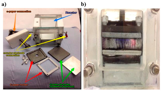
Figure 1.
(a) Digital image of the electrophoretic deposition (EPD) reactor used in this investigation. This photo is reproduced with permission from Wiley [43]; (b) digital photo showing how the nitrogen-doped graphene (N-G) particles move via electrophoretic forces to deposit on the carbon paper (CP) substrate on the top electrode.
2.6. Membrane-Electrode-Assembly (MEA)
The membrane employed was an AMI-7001S anion exchange membrane (International Inc., Ringwood, NJ, USA) as reported earlier [37]. The electrodes were GDL 10AA carbon papers of 0.4 mm thickness (SGL Carbon). These (excluding the membrane, which was separately soaked in 0.5 M TEABF4 dissolved in DES for a few days) were pre-treated by soaking them in 1-ethyl-1-methylpyrrolidinium bis(trifluoromethylsulfonyl)imide (as for the case of the pre-treated CP for CV experiments) for a few days inside an Ar-filled glove box prior to assembling in the battery and cycling the respective electrolyte at zero current. This procedure was considered crucial to enable sustained battery performance in this investigation. For the case of the IL, the membrane was separately soaked in an acetonitrile solution (containing 0.5 M TEABF4) for two days and then rinsed, dried, and assembled for battery testing.
2.7. Morphological Analysis
Carbon paper samples were subjected to scanning electron microscopy (SEM) by means of an Auriga-45-24 microscope with an accelerating voltage of 5 kV (pixel size = 29.46 nm). The CP samples after being rinsed with pure ethanol and dried were affixed on SEM stubs by means of conductive double-coated carbon tape. These were then stored in a vacuum desiccator until analysis via SEM.
A FEI TITAN 80/300 instrument was used to conduct high-resolution transmission electron microscopy (HRTEM) on CP samples (operating at 300 kV). Prior to HRTEM measurements, the samples were first suspended in pure ethanol by sonication (Branson) for up to 10 min. The dispersed samples were then drop-casted onto TEM copper grids (400 Cu Lacey carbon film supplied by Agar Scientific). A vacuum desiccator was employed to evaporate all of the ethanol from the samples on the TEM grids overnight. Finally, the grids (along with the CP samples) were placed inside a TEM sample holder for analysis.
X-ray computed micro-tomography (XCT) was employed to acquire transmission projection images of the CP as it was rotated through multiple angles in a similar manner as reported earlier [43]. The resulting contrast in each acquired image was a function of the attenuation coefficients or interference effects of the phases through which the X-rays were transmitted [44]. Both pristine CP and N-G/CP were mounted upright in a ceramic holder with a polymer support. 3D XCT imaging was subsequently conducted using a GE Nanotom S Laboratory Source [43]. For further details on the instrument operation, as well as post-image analysis (3D structure re-construction and calculation of surface areas and pore volumes by means of Avizo—FEI, France [7]), the reader is referred to our previous publication on reduced graphene oxide-modified carbon papers for aqueous vanadium redox flow battery applications [43].
2.8. Electrochemical Setup for CV
CV was performed in a three-electrode cell assembly [45]. The reference electrode was a silver wire immersed in an AgNO3 + TEABF4 solution containing acetonitrile (the reference electrode assembly was commercially sourced from BioLogic), whereas the counter electrode was a platinum (Pt) wire. The working electrodes were meticulously polished prior to each CV experiment with 0.25 µm alumina powdered suspensions and ultrasonically rinsed in acetone before being washed with the test solution. All electrochemical experiments were performed using a computer-controlled í-Autolab potentiostat (PGSTAT302N acquired from Metrohm), and the electrochemical cell was assembled inside a glove box at room temperature. Humidity levels were minimized by drying the ionic liquid or deep eutectic solvent using 4A molecular sieves. Prior to each cyclic voltammetric run, the electrolyte was sparged with pure Ar gas for at least 15 min, whilst, during the experiments, an inert atmosphere was always maintained above the solution level inside the glove box.
2.9. Redox Flow Battery Cell Assembly
An in-house designed and assembled reactor having a 5 cm2 active area was employed for RFB testing. The zero-gap flow-by RFB cell [5,31,32] is illustrated in Figure 2a along with a photo of the operational cell (Figure 2b). Graphite plates with a double serpentine flow-channel (CNC (Computer numerical control, and commonly) machined in-house) were employed for distributing the electrolyte across the active area and to electrically connect to the Cu current collector as for a previous study on aqueous-based VRFBs [31]. An AMI-7001S anion exchange membrane (International Inc. Ringwood, NJ, USA) was used in this work similar to a previous investigation using an H-type glass cell [37]. Single layers of SGL 10AA carbon paper (CP) were employed as the positive or negative electrodes. An approximate electrode compression of 20% was usually maintained by means of viton-gaskets (sourced from J-Flex) upon cell assembly. Additionally, the electrolyte delivery to each cell compartment via graphite flow manifold plates was performed by a peristaltic pump (Masterflex L/S Mod. 7323-80, Cole-Parmer, Saint Neots, UK). Prior to cell assembly, the carbon paper electrodes were pre-treated by soaking them in 1-ethyl-1-methylpyrrolidinium bis(trifluoromethylsulfonyl)imide (as mentioned above) for a few days inside an Ar-filled glove box to pre-condition them for experiments with the IL or DES electrolyte. The membrane was pre-treated separately as described in Section 2.6. The assembly and testing of the RFB cell were always conducted inside an Ar-controlled glove box.
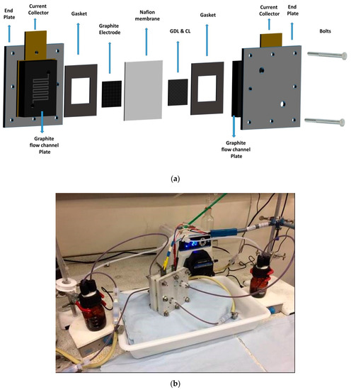
Figure 2.
(a) Cell components of the zero-gap redox flow batteries (RFB). The Nafion membrane from a previous investigation [46] was replaced with an anion exchange membrane. (b) Digital photo showing the zero-gap ionic liquid (IL) RFB under operation.
2.10. Charge–Discharge Experiments
When Vacac is used as the electro-active species for RFBs, a supporting electrolyte should be present to balance the charge of oxidized and/or active reduced species in the cell [41]. Therefore, for charge–discharge experiments, the positive and negative electrolytes consisted of a solution of 0.1 M vanadium (III) acetylacetonate along with 0.5 M TEABF4 that was dissolved in ethaline (1:2 eutectic ratio by mass of choline chloride and ethylene glycol, respectively) [47] as higher concentrations of the support were found to hinder active material solubility in acetonitrile [48]. The electrolyte volume in each reservoir was maintained around 50 mL. Before commencing any experiments, the RFB cell along with the electrolyte solutions were sparged with high-purity argon (BOC Gas & Gear, Morden, London, UK) continuously and were stirred during operation. Consequently, the electrolyte flowed into the RFB cell at 25 mL min−1. The continuous sparging with Ar was maintained to prevent environmental contamination, as well as to facilitate evaporation of any water that may have entered the system.
RFB cell charge and discharge cycles along with the anion exchange membrane were conducted galvanostatically at 10 mA cm−2. The first charge was performed up to a 90% theoretical state of charge (SOC) followed by electrochemical impedance spectroscopy, as described elsewhere [5]. Then, the RFB was charged and discharged to about a 70% theoretical SOC (20–95%) unless the cell voltage approached the cut-off value. The cut-off voltages were ~2.2 V for charging and 0.8 V for discharging in order to minimize overpotential losses and possible side reactions. When the first charge was completed, the RFB cell was maintained at its open-circuit voltage for two minutes. These measurements showed that the RFB cells reached a constant voltage within one minute upon completion of the first charge. All experiments were conducted at 45 °C, maintained by means of a thermostat (Fisher Scientific, Loughborough, UK).
Electrochemical impedance spectroscopy (EIS) was performed at the open-circuit voltage with an AC current root-mean-square value of 5 mA over a frequency range from 1 MHz to 100 mHz, and with 6 points per decade of frequency as reported elsewhere [5]. EIS measurements were conducted at the end of RFB charging as in a previous study [32]. The cell resistance was estimated from the high-frequency intercept of the Nyquist plot. A Bio-Logic potentiostat (VSP-300) with a 10 A booster running EC-Lab software was used to perform the RFB cycling and EIS measurements. Equivalent circuit analysis of the Nyquist plot was conducted using ZView (Scribner Associates, Inc. Southern Pines, NC, USA).
3. Results and Discussion
In this work, a standard DES was investigated and its performance was compared to a commercially sourced IL. The IL was chosen based upon its high conductivity and also its effective use in dye-sensitized solar cells [49]. After choosing the best non-aqueous electrolyte out of the two, flow battery experiments were performed to determine the effect of N-G/CP in comparison to a standard CP.
3.1. Physicochemical Properties of DES and IL
The viscosity, conductivity, and solubility of Vacac in the IL are given in Table 1. A comparison is also made with some common ILs that have been used for RFB testing in the literature. From these results, the property of the IL makes it ideal for use as a solvent for Vacac application in an RFB, especially due to its high conductivity and ability to dissolve 1 M of Vacac. This solubility was far greater than that reported for acetonitrile (of 0.6 M) [50]. By comparison, the DES appears to be marginally better than other ILs reported in the literature and, thus, it makes good sense to choose both of these solvents for further evaluation, especially as the DES has been used in a full RFB setup before [39]. The commercial prices in Table 1 also provide a good guide toward the selection of the IL and DES evaluated in this study.

Table 1.
Physicochemical properties of the IL and deep eutectic solvent (DES) tested in this work and their commercial rates compared to other ILs reported in the literature.
3.2. Cyclic Voltammetry of V(acac)3 in IL and DES with Glass Carbon (GC) Working Electrode
A cyclic voltammogram (CV) of 0.1 M V(acac)3 in the IL is displayed in Figure 3 (TEABF4 support is not used, because the IL is very conductive, as shown in Table 1). The CV is recorded at GC at a 10 mV s−1 scan rate. Two well-defined redox couples centered at −1.37 (Epc) and 0.63 (Epa) are visible. Similar CVs have been reported for other organic solvents, which are attributed to the V2+/V3+ and V3+/V4+ redox couples, respectively [14]. The potential difference, ΔE, between these redox couples is 2.2 V (as shown in Equations (1) and (2) below [52]), which is very similar to values of 2.61, 2.58, 2.31, and 2.21 V in tetrahydrofuran, 1,3-dioxolane, acetylacetone, and dimethyl sulfoxide, respectively [12].
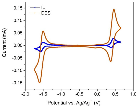
Figure 3.
Second cycles of CVs recorded at a 3 mm-diameter glass carbon (GC) disk electrode at 10 mV s−1 in 0.1 M V(acac)3 in IL (blue curve), and 0.1 M V(acac)3 in 0.5 M tetraethylammonium tetrafluoroborate (TEABF4) + DES (brown curve). All CVs began at the negative potential limit, and the blank CV is not shown, as it is similar to previously reported investigations [45].
The formal cell potential of the Vacac electrolyte is 2.2 V, and this is linked with the single-electron transfer reactions of V(acac)3 involving the V(III)/V(IV) couple at the positive electrode and the V(III)/V(II) couple at the negative electrode [52]:
[V(III) (acac)3] + e− ↔ [V(II) (acac)3]− E0 = −1.75 V vs. Ag/Ag+
[V(III) (acac)3] ↔ [V(IV) (acac)3]+ + e− E0 = 0.45 V vs. Ag/Ag+
At 0.1 M Vacac concentration, the CV of the DES is far better than that of the IL (Figure 3). Not only are the peak currents higher but the peak separations for each of the redox couples displayed in Equations (1) and (2) are also smaller. In an effort to understand how concentration variation of the active species affects its electrochemical properties in the IL, CVs were performed at different concentrations, as shown in Figure S1 (in Supplementary Materials). Interestingly, when the concentration of Vacac in IL was enhanced to 0.5 M, the redox behavior became more irreversible (Figure S1, Supplementary Materials). This may be because higher concentrations of Vacac may result in the ingress of moisture (as it is not always possible to remove all moisture from the vanadium salt or the IL despite the precautions taken), which results in the formation of VO(acac) (Vanadyl acetylacetonate or VO(acac) compounds) compounds that cause the electrochemically irreversible behavior [50]. Thus, a comparison of the IL with the DES at 0.1 M Vacac concentration was performed from here onwards.
Cyclic voltammograms (CVs) of 0.1 M V(acac)3 dissolved in the IL solution were measured in the potential range of 0.5 to −1.75 V at various scan rates (v = 50–300 mV s−1) and shown in Figure 4. CV data are available in Table 2 along with results of the DES from our previous investigation [15]. As the scan rate increases, two peaks are observed to move in the cathodic and anodic directions, respectively. The differences in peak potentials (ΔEp) between two cathodic peaks of the IL are approximately 120 and 171 mV at 50 and 300 mV s−1, respectively (Figure 4a). For the anodic peaks, the ΔEp values are approximately 90 and 140 mV at the same scan rates (Table 2 and Figure 4b). Irreversible kinetics is assumed for Equation (1) while reversible kinetics is attributed for Equation (2) as described below for the IL [53]. This is because with increasing scan rates, CV peaks become distorted for the reaction described by Equation (1) and is indicative of very poor electrochemical kinetics for this redox couple (Figure 4a).
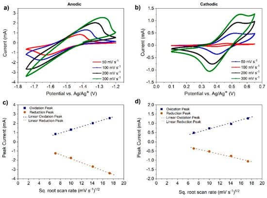
Figure 4.
Variation in peak currents of (a) V(II)/V(III) and (b) V(III)/V(IV) as a function of scan rates from CV data using the IL as an electrolyte. Calculations of the peak currents and their variation with the square root of CV scan rates for (c) V(II)/V(III) and (d) V(III)/V(IV) are also given to calculate diffusion coefficients from the Randles–Sevcik equation (Equation (3) for reversible kinetics and Equation (4) for irreversible kinetics).

Table 2.
Key CV data of 0.1 M V(acac)3 in the IL and DES in a three-electrode cell with a GC working electrode.
For the V(II)/V(III) redox couple in the DES (these results are from a previous work [37]), ΔEp shifted from 65 to 85 mV and the anodic-to-cathodic peak current ratio changed from 0.97 to 1.15 as with increasing scan rate from 50 to 300 mV s−1 [47]. ΔEp was observed to increase from 65 to 80 mV in the case of the V(III)/V(IV) redox couple; however, the anodic-to-cathodic peak current ratio diminished slightly from 1.1 to 0.98 with increasing scan rate in the DES (Table 2) [37].
For the reaction corresponding to Equation (1) in the IL, the values of the anodic and cathodic peak currents were raised up when the CV scan rate increased. Additionally, the ratio of peak currents for the forward and the reverse scans was close to unity (ipa/ipc = 1.0) and also scan rate-independent (as shown in Figure 4c,d) [46]. ΔEp from the CVs, at a range of scan rates, was estimated to lie between 0.09 and 0.18 V. A reversible, one-electron transfer reaction has a ΔEp = 0.059 V at 298 K. The deviation from 0.059 V at higher scan rates in the IL was attributed to poor electrochemical kinetics of the Vacac. However, in the case of the DES, the ratio of cathodic and anodic peak currents for the reaction corresponding to Equation (2) was close to unity although the peak-to-peak separation values were roughly the same as that for Equation (1), showing that the electrochemistry of Vacac was better in the DES (Table 2).
Considering the above discussion, the [V(II)]/[V(III)] electrochemical reaction was assumed to be irreversible at the respective scan rates for estimating the diffusion coefficients of [V(III)] in the IL. Similarly, the assumption of reversible kinetics was applied for [V(III)]/[V(IV)] to calculate the diffusion coefficients of [V(IV)] in the IL. For the DES, diffusion coefficients were obtained from a previous work [15].
The diffusion coefficients (D) were estimated by means of the Randles–Sevcik equation (Equation (3) for reversible kinetics and Equation (4) for irreversible kinetics), assuming that diffusion was the only mass transfer process of the electro-active species [46]. Accordingly [53], ipa and ipc are proportional to ν1/2 and, hence, a plot of ipa or ipc versus ν1/2 yields a straight line, the slope of which may be used to estimate the diffusion coefficient (as in Figure 4c,d).
where ip is the peak current (A), n is the number of equivalent electrons exchanged during the redox process (electron stoichiometry), F is Faraday’s constant (C mol−1), A is the electrode area (cm2), C0 is the bulk concentration of the electroactive species (mol cm−3), α is the transfer coefficient (usually assumed to be close to 0.5 for a one-electron reaction), ν is the voltage scan rate (V s−1), D is the diffusion coefficient of the electroactive species (cm2 s−1), R is the universal gas constant, and T is the absolute temperature (K).
Thus, the diffusion coefficient for the reaction corresponding to Equation (1) was 3.79 × 10⁻⁶, while that for Equation (2) was 2.35 × 10⁻⁶ cm2 s−1 in the IL (determined from Figure 4 and Table 2). These values were higher than those reported in the literature for other non-aqueous solvents utilizing Vacac [14,52]. Additionally, the diffusion coefficient for the reaction corresponding to Equation (1) in DES was 7.2 × 10⁻⁷ cm2 s−1 and that for Equation (2) was 6.7 × 10⁻⁷ cm2 s−1 [15], which were an order of magnitude lower than those of Vacac in the IL. These results were expected as the viscosity and conductivity of the IL were better than those of the DES, as shown in Table 1.
3.3. Cyclic Voltammetry of V(acac)3 in IL and DES with Pristine and N-G-Modified CP Electrodes
Prior to performing any charge and discharge experiments with the reactor shown in Figure 2, some CVs were performed by replacing the glassy carbon with carbon paper (CP) electrodes. CP electrodes were treated with 1-ethyl-1-methylpyrrolidinium bis(trifluoromethylsulfonyl)imide for at least 24 h prior to running CV experiments. If this pre-treatment was not performed, then the CV response would show poor electrochemistry, as seen in Figure 5a, which was obtained at a scan rate of 50 mV s−1.
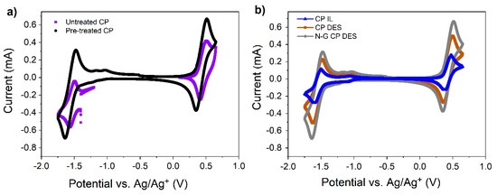
Figure 5.
(a) CV in untreated and pre-treated CP in the IL with 0.1 M V(acac)3 at 50 mV s−1 scan rate; (b) CV of 0.1 M V(acac)3 in the IL and DES at a scan rate of 20 mV s−1 using GDL 10 AA carbon paper as the working electrode.
CVs of DES and those of N-G-modified carbon paper electrodes in DES are shown in Figure 5b for pre-treated electrodes at 20 mV s−1. DES gives higher peak currents, which is amplified slightly when the pristine CP is replaced with N-G/CP. From the CV, it is clear that the N-G has positive effects on both redox couples that are described by means of Equations (1) and (2). Thus, the performance of a full battery is expected to be very good when the DES is used as electrolytes in combination with N-G-modified CP electrodes.
It is noted that a control experiment to show how N-G performs better than a standard graphene-modified CP would be of significant benefit for future DES-based RFB investigations. In this work, we did not show this comparison, because we realized from some past investigations by other workers that nitrogen doping significantly enhances RFB performance for aqueous, non-aqueous, and aqueous/organic systems [33,34,35]. However, future studies in taking this work forward is expected to report results from similar control experiments to further confirm the results reported from other investigations based on different electrolytes.
An interesting observation here is that because the CP samples were pre-treated with an electron-donating IL prior to CVs, their electrochemical performance was better than what is normally expected from a standard porous electrode due to ohmic drops and also possibly due to the degradation of V(acac)3 to VO(acac)2. The glassy carbon electrodes could not be treated in a similar manner, and it is anticipated that the shape of the CVs obtained from CPs was very similar to that obtained via GC electrodes (Figure 3) due to its electrode pre-treatment (Figure 5). In addition, we compensated for the IR drop due to solution resistance to generate the plots in Figure 5b, thereby ensuring that the shapes are very similar to those obtained from a flat GC working electrode. However, this needs to be systematically investigated in future as performed elsewhere for V(II)/V(III) electrochemistry in DES [54].
3.4. Charge/Discharge of V(acac)3 in IL and DES
The charge/discharge cycles were performed with a charge cut-off at 2.2 V and a discharge cut-off at 0.8 V of cell potential. These cut-offs were set for the current and operation time to avoid over-oxidation of electrolytes and electrodes. It is known that Vacac in non-aqueous electrolytes oxidizes at 0.45 V (with reference to Ag/Ag+) to form [V(acac)3]+, which reacts with water to produce VO(acac)2. VO(acac)2 then coordinates water or solvent molecules to form a chemically irreversible V(V) species [50]. This can be minimized if an electron-donating cationic compound is present in the solvent or in the supporting electrolyte [41]. As a consequence, the carbon paper electrodes were pre-treated by soaking them in 1-ethyl-1-methylpyrrolidinium bis(trifluoromethylsulfonyl)imide as described in the experimental section.
A small laboratory-scale reactor was employed for battery charge/discharge purposes using carbon paper electrodes (5 cm2) and the AMI-7001S membrane. Then, 0.1 M V(acac)3 was used as the active species dissolved in the ionic liquid or deep eutectic solvent. The second charge/discharge curve for the system at 45 °C is shown in Figure 6. The IL performance was compared to that of the model DES. The cell voltage for the DES remained close to its open-circuit voltage of 1.4 V and finally increased (for charging) or decreased (for discharging) to the respective cut-off values. The overcharging reported earlier [37] seemed to be minimized due to the presence of the electron-donating IL as a consequence of the electrode pre-treatment step [41], and this phenomenon was further minimized in the presence of N-G-modified electrodes due to a more enhanced electron-donating ability from the nitrogen-doped graphene [36].
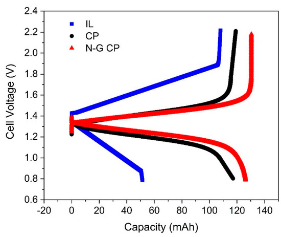
Figure 6.
Charge and discharge at 10 mA cm−2 of 0.1 M V(acac)3 in the IL and DES at 45 °C. Second cycle shown for the flow-by RFB, and the performance of N-G CP with its pristine counterpart (CP) is also shown for the DES (red and black curves, respectively). N-G CP gives the best capacity utilization along with high coulombic efficiencies.
The coulombic and energy efficiencies of the IL were 47% and 8%, being significantly lower than those for DES, which had a coulombic efficiency of 98% and an energy efficiency of 63%. Besides poor electrochemical kinetics of the Vacac in the IL, there was also some indication of membrane corrosion after operation beyond 12 h, confirming the observation reported by Ejigu and co-workers for other ILs [14]. Additionally, an unreported investigation by Rubio−Garcia showed that the IL was photo-degradable and needed operation under controlled lighting environments. Therefore, beyond this point, further evaluation of the IL was not pursued, and a comparison of the performance of DES in combination with N-G-modified CP electrodes was conducted instead (Figure 6). The overall energy efficiency of the RFB using DES increased to almost 75% with N-G-modified CP electrodes as expected, thereby confirming the results obtained by means of CV (Figure 5).
3.5. Charge/Discharge of V(acac)3 in DES at Different Current Densities and RFB Cycling Performance
The effect of varying applied current densities on overall cell efficiencies is displayed in Figure 7. Due to high viscosity and low conductivity of the DES, only very low current densities could be drawn. In future investigations, better DES electrolytes need to be chosen as reported for a vanadium/iron-based flow system [21], or the DES may be injected with carbon dioxide to enhance its performance [55]. Despite that, the operational current densities reported herein were better than that of the vanadium/iron flow system using a DES made from choline chloride and urea (reline) [21]. This is attributed to the pre-treatment of the electrodes using an electron-donating IL that ensured that the Vacac remained stable and did not decompose to its irreversible oxidized states [41].
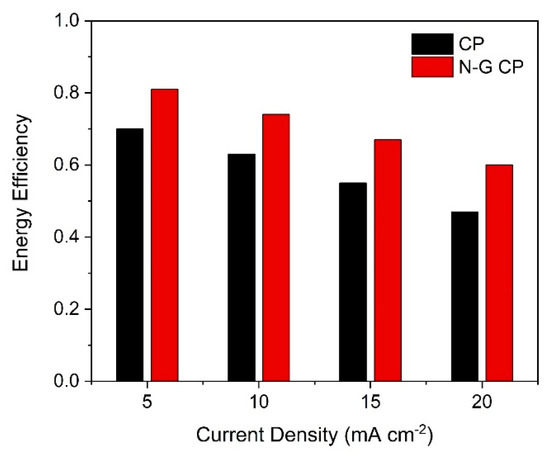
Figure 7.
Comparison of round-trip efficiencies with applied charge and discharge current densities in 0.1 M vanadium acetylacetonate (Vacac) with 0.5 M TEABF4 in DES at 45 °C.
In this work, the RFB was then cycled for at least 20 times to determine how its efficiencies and utilization varied with time. Figure 8 shows the cycling curves that display a marked improvement when employing N-G/CP electrodes. This is especially true for the energy efficiency of the battery; the decay in performance for the N-G/CP electrode is far less than that of pristine CP. This indicates that if this RFB is further optimized by means of material selection and MEA compression, then better performance may be obtained.
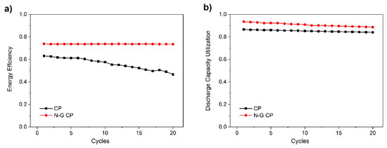
Figure 8.
Cycling of 0.1 M Vacac with 0.5 M TEABF4 in DES at 10 mA cm−2 and 45 °C showing (a) energy efficiencies and (b) discharge capacity utilization.
3.6. Electrochemical Impedance Spectroscopy of IL and DES in an Operational RFB
To understand how N-G improved the DES-based RFB performance, both EIS followed by a morphological analysis were conducted on pristine and N-G-modified CPs. EIS results for an uncharged flow-by cell showed a series resistance (RS) between 7 and 9 Ω (7 Ω for N-G CP in DES), which, although considered high, was not much compared to the resistance due to diffusion of active species in the carbon paper electrode, as shown in Figure 9a. The semi-depressed circle diameter is the lowest for the N-G-modified carbon paper (CP) electrode (Figure 9b). The EIS responses of pristine CP tested in IL, pristine CP tested in DES, and N-G-modified CP tested in DES have been fitted with an equivalent circuit in Figure 9c [5]. As the CP samples are porous in nature, the capacitor is replaced by a constant-phase element (CPE) in this equivalent circuit (may also be referred to as a modified Randles circuit). The decrease in charge transfer resistance (RCT) due to the better conductivity of N-G (Figure 9d) is mainly attributed to the good efficiency of the RFB in 20 cycles, as displayed in Figure 8. However, it was also necessary to determine if surface properties played a combined part; therefore, SEM, TEM, and XCT of the electrodes were performed as described below.
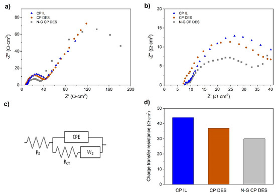
Figure 9.
Electrochemical impedance spectroscopy (EIS) after first charge at 10 mA cm−2. (a) Overall EIS; (b) EIS at high frequencies to determine charge transfer resistances; (c) equivalent circuit for estimating RCT; (d) comparison of charge transfer resistances of three electrodes in either IL- or DES-based electrolytes in a non-aqueous VRFB.
3.7. Morphological Characterization of CP Electrodes
Further, to comprehend the effect of N-G upon the morphological characteristics of the CP to effect enhanced performance of the DES, we performed high-resolution SEM and XCT. Figure 10a shows a nodal carbon fiber on pristine SGL CP covered with small pyrolyzed flakes from the manufacturing process of the supplier. By comparison, N-G almost fully covers the nodal carbon fiber after EPD, as shown in Figure 10b. HRTEM of the N-G isolated on a Cu grid is displayed in Figure 10c to show its transparent properties (close to few-layer graphene [32]). An XCT radiograph of N-G CP is displayed in Figure 10d, confirming the SEM image of Figure 10b whereby tiny flakes of N-G are seen next to different fiber nodes. A re-constructed X-ray image of the CP (green) with N-G deposited within the pores (blue) is shown in Figure 10e. This image is similar to that obtained with reduced graphene oxide deposited on the same CP as reported earlier [43].
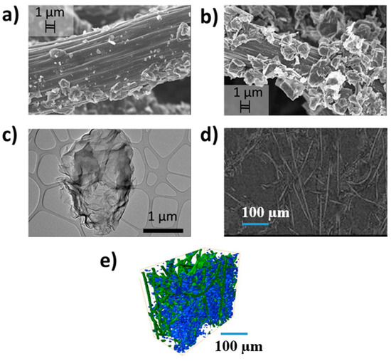
Figure 10.
(a) High-resolution SEM image of CP showing its fiber node at 1 µm along with pyrolyzed flakes from the manufacturing process (SGL Carbon); (b) SEM image of N-G CP showing a high density of multi-layered graphene flakes on the CP fiber at 1 µm; (c) high-resolution TEM of the N-G on copper grid at 1 µm; (d) X-ray tomography radiograph showing flakes of nanoparticles on carbon fiber nodes at 100 µm resolution; (e) X-ray computed micro-tomography (XCT) reconstructed image of the N-G/CP also at 100 µm resolution (similar to our previous paper published on reduced graphene oxide in Wiley [43]).
Further XCT experiments were carried out to compare the changes in surface area and volume of CP after being subjected to EPD in a similar manner as reported elsewhere [43]. The changes in porosity and volume-specific surface area (surface area divided by the sample volume) are shown in Table 3. The porosity measured for the pristine CP was found to be very similar to the value quoted by the manufacturer (SGL Carbon), which obviously becomes less when N-G is deposited via electrophoresis. It is clear that the specific surface area (determined from image processing datasets generated via XCT) increased by 35% after deposition of N-G on the CP. In addition, the volume (vol.%) of deposited carbon on the node shown in Figure 10a was almost doubled due to N-G. The ECSA obtained from CV also increases after N-G deposition (Table 3), which confirms that enhanced Vacac performance is obtained due to a combination of higher conductivity and better ECSA due to the presence of N-G (see Figure 6, Figure 7, Figure 8 and Figure 9).

Table 3.
Changes in porosity and specific surface area of CP after deposition of N-G as determined via XCT. Electrochemical surface area (ECSA) was estimated from CV.
3.8. Brief Perspective for Scaling-Up DES-Based RFBs
When RFBs are operated, the reactive transfer process has a major influence on system performance, which, in turn, is affected by the porous electrode morphology, as well as by the electrolyte transfer conditions [56]. The comparative data obtained for pristine carbon paper and the N-G-modified electrode via XCT can help in developing a better understanding on how electrode microstructural properties influence the RFB operational parameters by means of simulation studies, as has been performed for the vanadium/iron system in the ethaline-based DES recently [57]. In this regard, similar simulation studies could provide guidelines for researchers on how such parameters could be modified to enhance the operating current densities, which have a direct influence on reducing stack costs [58].
In addition, using a reline-based DES may show some improvements, but the need to operate at higher current densities than 2 mA cm−2 is essential if such systems could be considered for scaling-up [21]. This and other simulation studies suggest that enhancing the temperature of operation is likely to benefit DES-based batteries [56], but higher temperatures mean higher costs and also improved infrastructure design to handle elevated temperatures. As a consequence, it is imperative that different means of tailor-making DESs with active redox species present in the molecule could be useful. Density functional theory calculations may play a significant role in future studies [59]. Additionally, similar to the electro-catalytic modification reported in our present study, researchers may also infuse carbon-based electrodes with a urea-derived DES as reported elsewhere [60] and apply the same with reline as electrolytes in non-aqueous RFBs to effect higher current and power densities of operation. It would also be interesting to attempt preparing non-aqueous VRFB electrolytes by dissolving standard vanadium (IV) sulfate in either ethaline or reline for future investigations, as this is likely to prove more economical than employing Vacac.
Another extremely important component for enhancing performance is the selection of a good membrane to optimize the MEA for non-aqueous systems, as reported recently [17]. Taking these key RFB components into consideration, we performed an economic assessment of four non-aqueous systems (using prices from Table 1 and from the respective suppliers) based upon its time of operation, as shown in Figure S2 (Supplementary Materials). From this analysis, the reline-based DES is the most economical electrolyte for application in non-aqueous RFBs as reported by Xu and co-workers [21]. By comparison, acetonitrile is very expensive to use, highly toxic, flammable, and also volatile (resulting in loss of expensive solvent whilst in operation [10]), which means that the use of reline-based or similar DES may be the focus of future research endeavors.
4. Conclusions
In this work, a non-aqueous all-vanadium redox flow battery is evaluated by means of a relatively cheap and highly conductive ionic liquid, and its performance is compared to a deep eutectic solvent electrolyte. Despite much promise from the IL, the electrochemical performance of Vacac salt in the IL is poor and, therefore, its practical performance in a small-scale RFB is also poor, resulting in a round-trip energy efficiency of only 8% at a low operating current density of 10 mA cm−2. When this IL is replaced with a standard DES that has been evaluated for an all-copper RFB, the energy efficiency rises to 63%. In addition, the carbon paper electrodes are further modified with nitrogen-doped graphene by means of a one-step binder-free electrophoretic deposition process, which results in higher efficiencies of nearly 75%. This system can be operated temporarily at a higher current density of 20 mA cm−2 but more work is required to optimize the combination of electrolyte and membrane-electrode assembly to enhance the operating current density, which directly affects battery scaling-up and stack costs. In this respect, other DES electrolytes such as reline or tailor-made ones with active metal species bonded within the molecule may be attempted to replace the commonly investigated and yet expensive acetonitrile, which is also unsafe to handle and use.
Supplementary Materials
The following are available online at https://www.mdpi.com/2313-0105/6/3/38/s1. The Supplementary Materials contain two figures. Figure S1 shows CV scans of the ionic liquid at different concentrations of the active Vacac species. Figure S2 shows an estimated cost comparison between two deep eutectic solvents and an ionic liquid with respect to commonly used acetonitrile for non-aqueous redox flow batteries.
Author Contributions
Conceptualization, B.C. and J.R.-G.; methodology, E.K.; software, V.Y. and F.T.; validation, A.K., N.B. and C.T.J.L.; formal analysis, B.C. and J.R.-G.; investigation, E.K.; resources, N.B.; data curation, E.K. and F.T.; writing—original draft preparation, B.C.; writing—review and editing, B.C., J.R.-G. and E.K.; visualization, B.C. and J.R.-G.; supervision, A.K. and N.B.; project administration, B.C. and C.T.J.L.; funding acquisition, N.B. and C.T.J.L. All authors have read and agreed to the published version of the manuscript.
Funding
This research was partly funded by the EPSRC project Lower Cost and Longer Life Flow Batteries for Grid Scale Energy Storage (EP/L014289/1) and partly by EPSRC ISCF Wave 1: 3D electrodes from 2D materials (EP/R023034/1).
Acknowledgments
Authors are grateful to a UROP student from Chemical Engineering Department at Imperial College London (Christy Lam) for running some experiments with ionic liquids. Gratitude is also forwarded to our collaborators at Manchester University for providing some of the graphene samples.
Conflicts of Interest
The authors declare no conflict of interest. The funders had no role in the design of the study; in the collection, analyses, or interpretation of data; in the writing of the manuscript, and in the decision to publish the results.
References
- Leung, P.; Li, X.; Ponce de León, C.; Berlouis, L.; Low, C.T.J.; Walsh, F.C. Progress in redox flow batteries, remaining challenges and their applications in energy storage. RSC Adv. 2012, 2, 10125–10156. [Google Scholar] [CrossRef]
- Chen, C.L.; Yeoh, H.K.; Chakrabarti, M.H. One Dimensional Mathematical Modelling of the All-Vanadium and Vanadium/Oxygen Redox Flow Batteries. ECS Trans. 2015, 66, 1–23. [Google Scholar] [CrossRef]
- Ghimire, P.C.; Bhattarai, A.; Schweiss, R.; Scherer, G.G.; Wai, N.; Lim, T.M.; Yan, Q. Investigation of reactant conversion in the vanadium redox flow battery using spatially resolved state of charge mapping. Batteries 2019, 5, 2. [Google Scholar] [CrossRef]
- Bae, C.; Chakrabarti, H.; Roberts, E. A membrane free electrochemical cell using porous flow-through graphite felt electrodes. J. Appl. Electrochem. 2008, 38, 637–644. [Google Scholar] [CrossRef]
- Pino-Muñoz, C.A.; Chakrabarti, B.K.; Yufit, V.; Brandon, N.P. Characterization of a Regenerative hydrogen-vanadium fuel cell using an experimentally validated unit cell model. J. Electrochem. Soc. 2019, 166, A3511–A3524. [Google Scholar] [CrossRef]
- Chakrabarti, M.H.; Hajimolana, S.A.; Mjalli, F.S.; Saleem, M.; Mustafa, I. Redox flow battery for energy storage. Arab. J. Sci. Eng. 2013, 38, 723–739. [Google Scholar] [CrossRef]
- Tariq, F.; Rubio-Garcia, J.; Yufit, V.; Bertei, A.; Chakrabarti, B.K.; Kucernak, A.; Brandon, N. Uncovering the mechanisms of electrolyte permeation in porous electrodes for redox flow batteries through real time in situ 3D imaging. Sustain. Energy Fuels 2018, 2, 2068–2080. [Google Scholar] [CrossRef]
- Jiang, H.R.; Sun, J.; Wei, L.; Wu, M.C.; Shyy, W.; Zhao, T.S. A high power density and long cycle life vanadium redox flow battery. Energy Stor. Mater. 2020, 24, 529–540. [Google Scholar] [CrossRef]
- Ibrahim, O.A.; Kjeang, E. Leveraging co-laminar flow cells for non-aqueous electrochemical systems. J. Power Sources 2018, 402, 7–14. [Google Scholar] [CrossRef]
- Chakrabarti, M.H.; Dryfe, R.A.W.; Roberts, E.P.L. Evaluation of electrolytes for redox flow battery applications. Electrochim. Acta 2007, 52, 2189–2195. [Google Scholar] [CrossRef]
- Bamgbopa, M.O.; Pour, N.; Shao-Horn, Y.; Almheiri, S. Systematic selection of solvent mixtures for non-aqueous redox flow batteries – vanadium acetylacetonate as a model system. Electrochim. Acta 2017, 223, 115–123. [Google Scholar] [CrossRef]
- Herr, T.; Noack, J.; Fischer, P.; Tübke, J. 1,3-Dioxolane, tetrahydrofuran, acetylacetone and dimethyl sulfoxide as solvents for non-aqueous vanadium acetylacetonate redox-flow-batteries. Electrochim. Acta 2013, 113, 127–133. [Google Scholar] [CrossRef]
- Bamgbopa, M.O.; Almheiri, S. Influence of solvents on species crossover and capacity decay in non-aqueous vanadium redox flow batteries: Characterization of acetonitrile and 1, 3 dioxolane solvent mixture. J. Power Sources 2017, 342, 371–381. [Google Scholar] [CrossRef]
- Ejigu, A.; Greatorex-Davies, P.A.; Walsh, D.A. Room temperature ionic liquid electrolytes for redox flow batteries. Electrochem. Commun. 2015, 54, 55–59. [Google Scholar] [CrossRef]
- Bahadori, L.; Chakrabarti, M.H.; Hashim, M.A.; Manan, N.S.A.; Mjalli, F.S.; AlNashef, I.M.; Brandon, N.P. Temperature effects on the kinetics of ferrocene and cobaltocenium in methyltriphenylphosphonium bromide based deep eutectic solvents. J. Electrochem. Soc. 2015, 162, H617–H624. [Google Scholar] [CrossRef]
- Ge, X.; Gu, C.; Wang, X.; Tu, J. Deep eutectic solvents (DESs)-derived advanced functional materials for energy and environmental applications: Challenges, opportunities, and future vision. J. Mater. Chem. A 2017, 5, 8209–8229. [Google Scholar] [CrossRef]
- Kim, J.-H.; Ryu, S.; Maurya, S.; Lee, J.-Y.; Sung, K.-W.; Lee, J.-S.; Moon, S.-H. Fabrication of a composite anion exchange membrane with aligned ion channels for a high-performance non-aqueous vanadium redox flow battery. RSC Adv. 2020, 10, 5010–5025. [Google Scholar] [CrossRef]
- Karmakar, A.; Mukundan, R.; Yang, P.; Batista, E.R. Solubility model of metal complex in ionic liquids from first principle calculations. RSC Adv. 2019, 9, 18506–18526. [Google Scholar] [CrossRef]
- Wang, Y.; Niu, Z.; Zheng, Q.; Zhang, C.; Ye, J.; Dai, G.; Zhao, Y.; Zhang, X. Zn-based eutectic mixture as anolyte for hybrid redox flow batteries. Sci. Rep. 2018, 8, 5740. [Google Scholar] [CrossRef] [PubMed]
- Zhang, C.; Ding, Y.; Zhang, L.; Wang, X.; Zhao, Y.; Zhang, X.; Yu, G. A sustainable redox-flow battery with an aluminum-based, deep-eutectic-solvent anolyte. Angew. Chem. Int. Ed. 2017, 56, 7454–7459. [Google Scholar] [CrossRef]
- Xu, Q.; Qin, L.Y.; Ji, Y.N.; Leung, P.K.; Su, H.N.; Qiao, F.; Yang, W.W.; Shah, A.A.; Li, H.M. A deep eutectic solvent (DES) electrolyte-based vanadium-iron redox flow battery enabling higher specific capacity and improved thermal stability. Electrochim. Acta 2019, 293, 426–431. [Google Scholar] [CrossRef]
- Bahadori, L.; Chakrabarti, M.H.; Manan, N.S.A.; Hashim, M.A.; Mjalli, F.S.; AlNashef, I.M.; Brandon, N. The Effect of temperature on kinetics and diffusion coefficients of metallocene derivatives in polyol-based deep eutectic solvents. PLoS ONE 2015, 10, e0144235. [Google Scholar] [CrossRef]
- Chakrabarti, M.H.; Mjalli, F.S.; AlNashef, I.M.; Hashim, M.A.; Hussain, M.A.; Bahadori, L.; Low, C.T.J. Prospects of applying ionic liquids and deep eutectic solvents for renewable energy storage by means of redox flow batteries. Renew. Sustain. Energ. Rev. 2014, 30, 254–270. [Google Scholar] [CrossRef]
- Gencten, M.; Sahin, Y. A critical review on progress of the electrode materials of vanadium redox flow battery. Int. J. Energy Res. 2020. [Google Scholar] [CrossRef]
- Zhang, D.; Forner-Cuenca, A.; Taiwo, O.O.; Yufit, V.; Brushett, F.R.; Brandon, N.P.; Gu, S.; Cai, Q. Understanding the role of the porous electrode microstructure in redox flow battery performance using an experimentally validated 3D pore-scale lattice Boltzmann model. J. Power Sources 2020, 447, 227249. [Google Scholar] [CrossRef]
- Jervis, R.; Kok, M.D.R.; Neville, T.P.; Meyer, Q.; Brown, L.D.; Iacoviello, F.; Gostick, J.T.; Brett, D.J.L.; Shearing, P.R. In Situ compression and X-ray computed tomography of flow battery electrodes. J. Energy Chem. 2018, 27, 1353–1361. [Google Scholar] [CrossRef]
- Chakrabarti, M.H.; Low, C.T.J.; Brandon, N.P.; Yufit, V.; Hashim, M.A.; Irfan, M.F.; Akhtar, J.; Ruiz-Trejo, E.; Hussain, M.A. Progress in the electrochemical modification of graphene-based materials and their applications. Electrochim. Acta 2013, 107, 425–440. [Google Scholar] [CrossRef]
- Flox, C.; Rubio-García, J.; Skoumal, M.; Andreu, T.; Morante, J.R. Thermo–chemical treatments based on NH3/O2 for improved graphite-based fiber electrodes in vanadium redox flow batteries. Carbon 2013, 60, 280–288. [Google Scholar] [CrossRef]
- Chakrabarti, M.H.; Brandon, N.P.; Hajimolana, S.A.; Tariq, F.; Yufit, V.; Hashim, M.A.; Hussain, M.A.; Low, C.T.J.; Aravind, P.V. Application of carbon materials in redox flow batteries. J. Power Sources 2014, 253, 150–166. [Google Scholar] [CrossRef]
- Chang, Y.-C.; Shih, Y.-C.; Chen, J.-Y.; Lin, G.-Y.; Hsu, N.-Y.; Chou, Y.-S.; Wang, C.-H. High efficiency of bamboo-like carbon nanotubes on functionalized graphite felt as electrode in vanadium redox flow battery. RSC Adv. 2016, 6, 102068–102075. [Google Scholar] [CrossRef]
- Chakrabarti, B.; Nir, D.; Yufit, V.; Aravind, P.V.; Brandon, N. Enhanced performance of an All-Vanadium redox flow battery employing graphene modified carbon paper electrodes. Int. J. Chem. Mol. Eng. 2017, 11, 622–626. [Google Scholar]
- Chakrabarti, B.; Yufit, V.; Kavei, A.; Xia, Y.; Stevenson, G.; Kalamaras, E.; Luo, H.; Feng, J.; Tariq, F.; Taiwo, O.; et al. Charge/discharge and cycling performance of flexible carbon paper electrodes in a regenerative hydrogen/vanadium fuel cell. Int. J. Hydrog. Energy 2019, 44, 30093–30107. [Google Scholar] [CrossRef]
- Cao, J.; Zhu, Z.; Xu, J.; Tao, M.; Chen, Z. Nitrogen-doped porous graphene as a highly efficient cathodic electrocatalyst for aqueous organic redox flow battery application. J. Mater. Chem. A 2017, 5, 7944–7951. [Google Scholar] [CrossRef]
- Cao, J.; Ding, F.; Chen, H.; Wang, H.; Wang, W.; Chen, Z.; Xu, J. A new redox-active conjugated polymer containing anthraquinone pendants as anode material for aqueous all-organic hybrid-flow battery. J. Power Sources 2019, 423, 316–322. [Google Scholar] [CrossRef]
- Zhang, Y.; Liu, W.; Wang, Z.; Shen, Y.-M.; Wang, W.; Chen, Z.; Xu, J.; Cao, J. Tetrapyridophenazine/graphene composites for aqueous hybrid flow battery anodes with long cycle life. Carbon 2020, 161, 309–315. [Google Scholar] [CrossRef]
- Yang, D.-S.; Lee, J.Y.; Jo, S.-W.; Yoon, S.J.; Kim, T.-H.; Hong, Y.T. Electrocatalytic activity of nitrogen-doped CNT graphite felt hybrid for all-vanadium redox flow batteries. Int. J. Hydrog. Energy 2018, 43, 1516–1522. [Google Scholar] [CrossRef]
- Bahadori, L.; Hashim, M.A.; Manan, N.S.A.; Mjalli, F.S.; AlNashef, I.M.; Brandon, N.P.; Chakrabarti, M.H. Investigation of Ammonium- and phosphonium-based deep eutectic solvents as electrolytes for a Non-aqueous All-Vanadium redox cell. J. Electrochem. Soc. 2016, 163, A632–A638. [Google Scholar] [CrossRef]
- Chakrabarti, M.H.; Manan, N.S.A.; Brandon, N.P.; Maher, R.C.; Mjalli, F.S.; AlNashef, I.M.; Hajimolana, S.A.; Hashim, M.A.; Hussain, M.A.; Nir, D. One-pot electrochemical gram-scale synthesis of graphene using deep eutectic solvents and acetonitrile. Chem. Eng. J. 2015, 274, 213–223. [Google Scholar] [CrossRef]
- Lloyd, D.; Vainikka, T.; Kontturi, K. The development of an all copper hybrid redox flow battery using deep eutectic solvents. Electrochim. Acta 2013, 100, 18–23. [Google Scholar] [CrossRef]
- Park, S.K.; Oh, C.J.; Kim, S.-G.; Lee, B.-J.; Lee, J.H.; Lee, J.S. Effect of functionalized ionic liquids on the stability of V(acac)3. B. Korean Chem. Soc. 2018, 39, 1036–1040. [Google Scholar] [CrossRef]
- Xing, Z.; Ju, Z.; Zhao, Y.; Wan, J.; Zhu, Y.; Qiang, Y.; Qian, Y. One-pot hydrothermal synthesis of Nitrogen-doped graphene as high-performance anode materials for lithium ion batteries. Sci. Rep. 2016, 6, 26146. [Google Scholar] [CrossRef] [PubMed]
- Chakrabarti, B.; Nir, D.; Yufit, V.; Tariq, F.; Rubio-Garcia, J.; Maher, R.; Kucernak, A.; Aravind, P.V.; Brandon, N. Performance enhancement of reduced graphene Oxide-Modified carbon electrodes for vanadium redox-flow systems. ChemElectroChem 2017, 4, 194–200. [Google Scholar] [CrossRef]
- Wu, Y.; Holze, R. Electrocatalysis at Electrodes for Vanadium Redox Flow Batteries. Batteries 2018, 4, 47. [Google Scholar] [CrossRef]
- Tariq, F.; Yufit, V.; Kishimoto, M.; Shearing, P.R.; Menkin, S.; Golodnitsky, D.; Gelb, J.; Peled, E.; Brandon, N.P. Three-dimensional high resolution X-ray imaging and quantification of lithium ion battery mesocarbon microbead anodes. J. Power Sources 2014, 248, 1014–1020. [Google Scholar] [CrossRef]
- Chakrabarti, M.H.; Brandon, N.P.; Mjalli, F.S.; Bahadori, L.; Al Nashef, I.M.; Hashim, M.A.; Hussain, M.A.; Low, C.T.J.; Yufit, V. Cyclic Voltammetry of Metallic Acetylacetonate Salts in Quaternary Ammonium and Phosphonium Based Deep Eutectic Solvents. J. Solut. Chem. 2013, 42, 2329–2341. [Google Scholar] [CrossRef]
- Rubio-Garcia, J.; Kucernak, A.; Parra-Puerto, A.; Liu, R.; Chakrabarti, B. Hydrogen/functionalized benzoquinone for a high-performance regenerative fuel cell as a potential large-scale energy storage platform. J. Mater. Chem. A 2020, 8, 3933–3941. [Google Scholar] [CrossRef]
- Chakrabarti, M.H.; Brandon, N.P.; Hashim, M.A.; Mjalli, F.S.; AlNashef, I.M.; Bahadori, L.; Manan, N.S.A.; Hussain, M.; Yufit, V. Cyclic voltammetry of iron (III) acetylacetonate in quaternary ammonium and phosphonium based deep eutectic solvents. Int. J. Electrochem. Sci. 2013, 8, 9652–9676. [Google Scholar]
- Shinkle, A.A.; Pomaville, T.J.; Sleightholme, A.E.S.; Thompson, L.T.; Monroe, C.W. Solvents and supporting electrolytes for vanadium acetylacetonate flow batteries. J. Power Sources 2014, 248, 1299–1305. [Google Scholar] [CrossRef]
- Marszalek, M.; Fei, Z.; Zhu, D.-R.; Scopelliti, R.; Dyson, P.J.; Zakeeruddin, S.M.; Grätzel, M. Application of ionic liquids containing tricyanomethanide [C(CN)3]− or Tetracyanoborate [B(CN)4]− Anions in Dye-sensitized solar cells. Inorg. Chem. 2011, 50, 11561–11567. [Google Scholar] [CrossRef]
- Shinkle, A.A.; Sleightholme, A.E.S.; Griffith, L.D.; Thompson, L.T.; Monroe, C.W. Degradation mechanisms in the non-aqueous vanadium acetylacetonate redox flow battery. J. Power Sources 2012, 206, 490–496. [Google Scholar] [CrossRef]
- Chen, R.; Hempelmann, R. Ionic liquid-mediated aqueous redox flow batteries for high voltage applications. Electrochem. Commun. 2016, 70, 56–59. [Google Scholar] [CrossRef]
- Liu, Q.; Sleightholme, A.E.S.; Shinkle, A.A.; Li, Y.; Thompson, L.T. Non-aqueous vanadium acetylacetonate electrolyte for redox flow batteries. Electrochem. Commun. 2009, 11, 2312–2315. [Google Scholar] [CrossRef]
- Flox, C.; Skoumal, M.; Rubio-Garcia, J.; Andreu, T.; Morante, J.R. Strategies for enhancing electrochemical activity of carbon-based electrodes for all-vanadium redox flow batteries. Appl. Energy 2013, 109, 344–351. [Google Scholar] [CrossRef]
- Xu, Q.; Qin, L.; Su, H.; Xu, L.; Leung, P.; Yang, C.; Li, H. Electrochemical and transport characteristics of V(II)/V(III) Redox Couple in a nonaqueous deep eutectic solvent: Temperature effect. J. Energy Eng. 2017, 143, 04017051. [Google Scholar] [CrossRef]
- Xu, Q.; Ji, Y.N.; Qin, L.Y.; Leung, P.K.; Shah, A.A.; Li, Y.S.; Su, H.N.; Li, H.M. Effect of carbon dioxide additive on the characteristics of a deep eutectic solvent (DES) electrolyte for non-aqueous redox flow batteries. Chem. Phys. Lett. 2018, 708, 48–53. [Google Scholar] [CrossRef]
- Ma, Q.; Xu, Q.; Chen, Q.; Chen, Z.; Su, H.; Zhang, W. Lattice Boltzmann model for complex transfer behaviors in porous electrode of all copper redox flow battery with deep eutectic solvent electrolyte. Appl. Therm. Eng. 2019, 160, 114015. [Google Scholar] [CrossRef]
- Abbas, Q.; Fitzek, H.; Pavlenko, V.; Gollas, B. Towards an optimized hybrid electrochemical capacitor in iodide based aqueous redox-electrolyte: Shift of equilibrium potential by electrodes mass-balancing. Electrochim. Acta 2020, 337, 135785. [Google Scholar] [CrossRef]
- Barton, J.L.; Brushett, F.R. A One-Dimensional stack model for redox flow battery analysis and operation. Batteries 2019, 5, 25. [Google Scholar] [CrossRef]
- Naik, P.K.; Paul, S.; Banerjee, T. Physiochemical properties and molecular dynamics simulations of phosphonium and ammonium based deep eutectic solvents. J. Solut. Chem. 2019, 48, 1046–1065. [Google Scholar] [CrossRef]
- Kawase, K.; Abe, J.; Tenjimbayashi, M.; Kobayashi, Y.; Takahashi, K.; Shiratori, S. Novel Deep-Eutectic-Solvent-Infused carbon nanofiber networks as high power density green battery cathodes. ACS Appl. Mater. Interfaces 2018, 10, 15742–15750. [Google Scholar] [CrossRef]
© 2020 by the authors. Licensee MDPI, Basel, Switzerland. This article is an open access article distributed under the terms and conditions of the Creative Commons Attribution (CC BY) license (http://creativecommons.org/licenses/by/4.0/).