1. Introduction
After two decades of intensive material development, lithium-ion (Li-Ion) cells have been commercialized by Sony in 1991 [
1]. Due to many excessive failures of rechargeable Li cells beforehand, Li-Ion cells have undergone a tremendous evolution in the last decades [
2]. Nowadays, people get more and more convinced that Li-Ion technology is the most appropriate solution to successfully power electric vehicles and stationary batteries. Furthermore, assuming certain factors, particularly the level of usage, cost competitiveness of traction batteries over combustion engines is already given today [
3]. However, there is an ongoing demand of users and manufacturers for increasing energy density. As the current Li-Ion cell technology is reaching its limits of energy density, one promising way for further enhancement is using alternative electrode materials. Li is one candidate for replacing graphite in the negative electrode [
4]. Apart from the extraordinary specific capacity of Li of 3860 mAh/g, which is about a factor of 10 over conventional graphite, the full cell voltage can also be increased by the very low electrochemical potential of −3.04 V versus the standard hydrogen electrode. As a result, specific energy [Wh/kg] can be increased by 35% and energy density [Wh/L] by 50% [
5].
In order to provide excess Li on the negative electrode, one opportunity is to manufacture Li anodes before cell assembly. Apart from highest demands to dry rooms as well as nitrogen and carbon dioxide content in the air, in order not to contaminate the highly sensitive Li surface, it is not evident how such Li electrodes can be efficiently implemented in a high speed cell assembly process such as required for GWh-factories as well as being a part of a roll to roll concept [
6,
7].
To harness these huge advantages in cell potential and charge density and to overcome the above mentioned disadvantages by employing any externally manufactured Li foil, another approach is to deposit a Li layer upon first formation in situ in the cell. This raises various challenges. Especially the common way to add some sacrificial excess Li to the negative electrode [
8] to improve cyclability is obsolete then. On the one hand, this is best for energy density enhancement and manufacturing aspects but on the other hand, it adds a tremendous hurdle for the life time, especially due to excess Li depletion of the cathode upon cycling, due to insufficient Coulombic efficiencies. Using the method presented in [
9], it can be calculated that a mean Coulombic efficiency of
is needed to reach 1000 full-cycles with 80% capacity remaining assuming no Li excess in the cell.
Currently the poor cyclability, as well as safety issues, generally prevent the breakthrough of Li cells operated at ambient temperature. Among other issues, the main reasons for that, as depicted in
Figure 1a, are volume changes during cycling and the formation of fine Li dendrites [
10,
11] with a high surface area which favors side reactions on the anode. The resulting crack formation and constant renewal of the solid electrolyte interphase (SEI) causes an unacceptable consumption of liquid electrolyte leading to a decreasing ionic conductivity and loss of active Li [
12]. Moreover “dead” Li is the result of contact loss of Li to the electrode surface [
13]. Additionally, dendrites carry the risk of short-circuiting the cell, followed by a thermal runaway [
14].
One way to counter dendrite growth and its associated problems is the use of structured current collectors instead of planar copper (Cu) foils (
Figure 1b) for the Li plating/stripping processes during cycling [
15]. A schematic representation of the operating principle for this kind of current collectors is presented in
Figure 1. The reason for the growth of Li dendrites can be attributed to the inhomogeneously distributed current density on the electrode surface. Protrusions form preferred nucleation sites for Li-deposition. Due to the texturing of the current collector, both the surface area and the number of nucleation sites are increased, whereby the current density becomes more uniform. This favors homogeneous and reversible Li deposition [
16].
For the envisaged target to deposit Li in-situ in the cell, test cells with both Li as well as lithium nickel cobalt manganese oxide (NCM) as counter electrodes are set up versus different Cu-based current collectors and are cycled. As reference, a flat Cu foil is used and compared with a current collector made of chemically separated brass foil. When comparing test results of different structured current collectors, there are several aspects to be considered. One of these is to separate improvements in cycle performance, which can either be achieved by micro-structured current collectors or by using different electrolytes.
Thus, to emphasize a structured current collector’s influence on cyclability of a Li electrode, a compromise regarding the choice of the liquid electrolyte can be beneficial. In our view, an electrolyte promoting enough stability of the Li electrode to allow for valid results is needed. Some electrolyte’s impact on the Li plating/stripping process might superimpose the structured current collector’s benefit to increased Coulombic efficiency in a way, the actual studied effect becomes invisible. The commonly used electrolyte for Li-Ion cells with lithium hexafluorophosphate (LiPF
6) in ethylene carbonate (EC) and diethyl carbonate (DEC) [
17] is not perfectly suitable for the application in Li cells. However, additives like fluoroethylene carbonate (FEC) render sufficient stability of the Li electrode’s passivation layer to allow for more stable cycling [
18].
As already indicated, besides the use of structured current collectors, another approach for improving the cyclability of Li electrodes is using another electrolyte. A recent study brings into question the need for the much discussed solid electrolyte [
19,
20] for realizing Li electrodes [
21]. It is demonstrated that cells containing Li electrodes can be cycled repeatedly using liquid electrolyte. Especially high concentrations of Li salts [
22] and ether solvents [
23] have been studied intensively lately. Highly concentrated electrolytes provide less uncoordinated solvent molecules and are therefore less prone to reductive decomposition. In [
24] the effect of different concentrations of lithium bis(fluorosulfonyl)imide (LiFSI) in 1,2-dimethoxyethane (DME) have been investigated on their effect on the cycling stability of Li electrodes. It could be shown that a concentration of 2 M LiFSI provides an appropriate SEI composition. The high LiF content within the built SEI causes high ion diffusivity and mechanical stability enabling a stable passivization of the subjacent Li electrode.
The two presented methods for improving the cycling performance of Li electrodes are investigated in many publications. For experiments with structured current collectors usually electrolytes with 1 M salt concentration are used. The contribution of this publication is to combine a structured Cu current collector with adapted electrolyte in Li cells and to compare the obtained cycle results with those of unstructured current collectors and normally concentrated electrolytes. Each test is conducted against Li and NCM counter electrodes.
2. Experimental
Reference current collector: To show the impact of the different structures on the cycling behavior, an untreated and unstructured planar foil made of oxygen-free Cu from
SCHLENK Metal Foils GmbH & Co. KG., Roth, Germany with a thickness of
is used as reference. Punched out as a coin with a diameter
, this current collector has an effective surface for the Li deposition of
. The planar Cu foil is used as received. In
Figure 2a, a schematic representation of the pure Cu foil and a microscope image with a magnification of 150 are shown.
Chemically separated brass foil: Alloys consisting of metals with individual solubilities can be separated by chemical treatment. Using hydrochloric acid (HCl) as etching solution for brass (CuZn), the less noble constituent zinc (Zn) can be dissolved while Cu remains solid and builds a three dimensional framework with large specific surface area.
Figure 2b depicts a scheme of the manufacturing process of the CuZn foil and microscope images before and after the etching process with a magnification of 150. The idea of using this method for the manufacturing of an etched brass foil as current collector is based on [
25,
26] and is also applied with slight modification in [
27,
28] with a vacuum distillation method for dealloying. The used brass foil provided by
H+S PRÄZISIONSFOLIEN Gmb, Pirk, Germany with a thickness of
consists of 63% Cu with a zinc content of 37%. For the preparation, the foil is inserted in 37% hydrochloric acid at
for about two hours. After this process, a color change from brass to Cu is visible, indicating that the dealloying process was successful. The weight loss of about 37% during the etching process confirms the assumption that all of the Zn is removed from the foil.
Cell assembly, separator, electrolyte, and counter electrodes: Before cell assembly, all current collectors are dried under vacuum for at . Subsequently, the foils are transferred into an argon-filled glove box by MBRAUN with an oxygen and a water concentration of .
Cells are assembled using EL-CELLs PAT-Cell cases. Each cell contains electrolyte which is dripped onto the separator (one single layer of Celgard 2500) during cell assembly. The carbonate-based electrolyte consists of 1 M lithium hexafluorophosphate (LiPF6) in a solvent mixture of ethylene carbonate (EC) and diethyl carbonate (DEC) with a weight ratio of 1:1. Fluoroethylene carbonate (FEC, BASF, Ludwigshafen am Rhein, Germany) is added until a concentration of 10 wt.% is obtained. The carbonate-basaed electrolyte’s components are provided by BASF, Ludwigshafen am Rhein, Germany. The ether-based electrolyte consists of 2 M LiFSI (>99% Ionic Liquid Technologies GmbH, Heilbronn, Germany) in DME (>99% Thermo Fisher GmbH, Kandel, Germany). As for the Li counter electrode, a Li foil with a thickness by Sigma Aldrich, St. Louis, USA is used and cleaned before assembly. The punched Li electrodes with a diameter of provide an amount of Li equivalent to a capacity of .
Lithium nickel cobalt manganese oxide (LiNi0.6Co0.2Mn0.2O2 (NCM 622)) counter electrodes with a specific capacity of are provided by Münster Electrochemical Energy Technology (MEET). The electrode’s composition by mass is 95% active material, 2% carbon black and 3% Poly(vinylidene fluoride) binder.
For each experiment, multiple cells are built and cycled to calculate mean values and standard deviations of the results. The tests are conducted using a Basytec CTS, Asselfingen, Germany battery cells tester in climate chambers by Memmert, Schwabach, Germany at a constant temperature of . Prior to applying current, the cells are left for one hour in the climate chamber for homogeneous electrolyte distribution and cell temperature adjustment. The following cycling is done at constant current at a current density of . For experiments against a Li electrode, a Li amount corresponding to a specific charge amount of is deposited on the current collector during the lithiation process. In the subsequent delithiation procedure, Li is stripped from the current collector until a cell voltage of is reached. For experiments against NCM “shallow cycling” is applied. This means, as long as cell voltage boundaries of can be satisfied each cycle consists of a lithiation step in which a specific charge amount of is deposited on the current collector.
All area specific current densities and charge amounts are related to the planar surface area of the current collector .
Cycling results are evaluated on the basis of the mean Coulombic efficiency and reached number of valid cycles before cell failure. The Coulombic efficiency of one cycle is interpreted as the charge amount that can be stripped from the current collector in relation to the charge amount that has previously been deposited onto it.
Cycling experiments are aborted as soon as the delithiation capacities of five consecutive cycles drop below
as shown in
Figure 3. The number of the last cycle with a delithiation capacity of
also represents the maximum number of valid cycles
. Mean Coulombic efficiency
is the mean of the Coulombic efficiencies of all cycles
.
3. Results and Discussion
At first, the influence of the structured current collector and the counter electrode shall be discussed. Therefore,
Figure 4 shows the cycle results regarding the mean Coulombic efficiency
and the reached number of cycles
for the cycle experiments of two different current collectors (planar Cu and etched brass foil) for the negative electrode each cycled with Li foil and NCM as counter electrode. For all experiments, an electrolyte of 1 M LiPF
6 EC:DEC:FEC with a weight ratio of 4.5:4.5:1 is used and considering voltage boundaries, the same amount of charge
is attempted to be plated onto the current collector and stripped from it again in the following step.
Figure 4a depicts cycle results of a planar Cu foil and an etched brass foil against a Li counter electrode. Results are represented as the mean values of multiple tests with the respective deviation. Etched brass foil with a mean Coulombic efficiency of
and a mean maximum number of cycles
shows hardly any improvement compared to planar Cu foil (
and
).
In
Figure 4b, cycle results of the planar Cu and the etched brass foil against NCM counter electrodes are shown. In this comparison, etched brass foil (
and
) shows notable improvement over planar Cu foil (
and
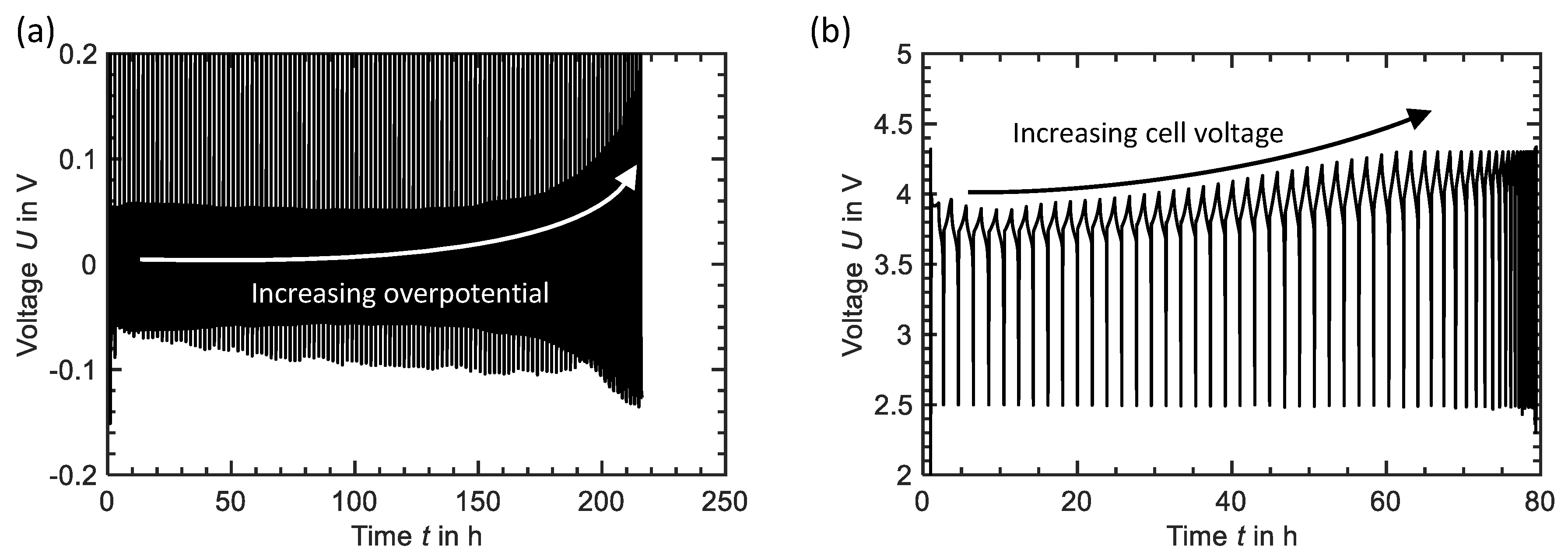
). We ascribe this effect, namely the more obvious difference in cycle performance compared to the carbonate-based electrolyte experiments, to the respective counter electrode. The cell setups with Li counter electrode suffer from continuous electrolyte decomposition not only on the working electrode but also on the Li counter electrode. The result of this side reaction is visible in the voltage profiles in
Figure 5a in the form of excessively increasing overpotential. Especially at the end of the cycle experiment, when almost the entire electrolyte has decomposed voltage rises exponentially followed by a sudden decrease that might be caused by short-circuit [
29]. The reason for the failure of experiments with Li counter electrodes, therefore, is the limited amount of electrolyte respectively its decomposition by the formation and constant renewal of the SEI. After disassembling the cell, post-mortem analysis confirms this assumption, as there is no liquid electrolyte left on the separator and a solid surface layer on the electrode’s surfaces can be observed.
The cells with the more inert NCM counter electrode, however, undergo severe electrolyte decomposition only on the negative electrode’s surface [
30]. The increasing cell voltage in
Figure 5b can be ascribed to the loss of the limited amount of active Li in the cell. Continuous Li consumption reduces the maximum possible lithiation degree of the NCM electrode and therefore raises its potential vs. Li. It may be concluded that failure of experiments in cells with Li counter electrodes therefore is mainly caused by the limited amount of electrolyte while cells with NCM counter electrode suffer from limited amount of active Li.
Considering the results presented in
Figure 4, we assume that in cells with Li as counter electrode the benefit regarding improved Coulombic efficiency of structured versus planar current collectors might be overlaid by the additional electrolyte decomposition on the counter electrode surface.
A possible explanation for the improved cycle performance of Li electrodes with structured current collector might be the following: compared to intercalation electrodes electrochemical Li plating onto current collectors lacks the ordered incorporation of ions into vacant interstitial sites [
31]. However, it is assumed that the increased surface area of structured current collectors results in a more homogeneous electric field. The pore structure facilitates three dimensional Li deposition whereas the fine and evenly distributed protrusions act as favored nucleation sites. Thus Li deposition is less prone to dendrite formation and volume changes of the negative electrode are reduced. This results in lower mechanical stress on the SEI formed on the Li’s surface and therefore improved Coulombic efficiency. Taking a look at the electrolyte wetting process, the three dimensional structure of the structured current collector can be confirmed. During the electrolyte filling process, it can be seen that all of the structured current collector’s surface becomes impregnated including pores and even the side of the structure averted from the separator. This allows for three dimensional lithiation of the current collector with utilization of the pore volume and can also be verified by fine Li spots that are visible when looking at the backside of the lithiated structured current collector after disassembling the cell as shown in
Figure 6.
As already mentioned, besides the structuring of the Li electrodes current collector, another approach for achieving further improvement of Coulombic efficiency is adapting the electrolyte. In
Figure 7a, cycle performance results of tests with the ether-based LiFSI electrolyte are shown as the mean and the standard deviation of multiple cells. During
cycles, the cells with planar Cu as the current collector achieve a mean Coulombic efficiency of
. The standard deviation of these tests is noticeably high, due to two outliers. The cells with the etched brass foil as current collector show a very similar result (
,
). For easier comparison, the results of experiments with carbonate based electrolyte from
Figure 4 are also shown in
Figure 7. As with the carbonate-based cells, there is hardly any notable difference concerning cycle performance when comparing cells with planar Cu and etched brass foil as current collector in ether-based electrolyte. However, a significant improvement of the cycle performance of Li electrodes by adapting the electrolyte is visible. This observation might be a confirmation of the before mentioned assumption of the positive effect of the optimized electrolyte superimposing the beneficial effect of the structured current collector.
Figure 7b shows cycle results of Li electrodes with planar Cu respective etched brass foil as current collector against NCM electrodes. Both results with carbonate-based and ether-based electrolyte are displayed. Regarding the mean of all conducted experiments, the obtained result with carbonate-based electrolyte can not be confirmed. With a mean Coulombic efficiency of
over
cycles, the cycle performance of etched brass foil as current collector with ether based electrolyte is significantly worse when compared with planar Cu foil (
over
). This may as well be interpreted as a confirmation of the aforementioned assumption that the beneficial effect of optimized electrolytes superimpose improvements in cycle performance achieved by structured current collectors. However, there is one outlier (
over
) in the experiment with etched brass foil. Comparing just the best results of each experiment with NCM counter electrode and carbonate-based respectively ether-based electrolyte, another tendency becomes visible. That is cycle performance of Li electrodes seems to benefit from the herein presented method of structuring the current collector in combination with both of our tested electrolytes. In case of experiments with ether-based electrolyte and NCM electrodes current collector corrosion [
32] has to be considered. Despite this fact, cycle performance of Li electrodes against NCM is strongly improved by replacing carbonate- with ether-based electrolytes due to their ability to suppress dendritic Li growth [
33].


