Abstract
Solid Al–air batteries are a promising power source for potable electronics due to their environmentally friendly qualities and high energy density. However, the solid Al–air battery suffers from anodic corrosion and it is difficult to achieve a higher specific capacity. Thus, this work aims at suppressing the corrosion of Al anode by adding an electrospun Al2O3 interlayer on to the surface of the anode. The Al2O3 interlayer effectively inhibits the self-corrosion of the Al anode. Further, the effects of the thickness of the Al2O3 film on corrosion behavior were investigated. The results showed that the Al–air battery with a 4 μm Al2O3 interlayer is more suitable for a low current density discharge, which could be applied for mini-watt devices. With a proper thickness of the Al2O3 interlayer, corrosion of the anode was considerably suppressed without sacrificing the discharge voltage at a low current density. The Al–air battery with a 4 μm Al2O3 interlayer provided a significantly high capacity (1255 mAh/g at 5 mA/cm2) and an excellent stability. This wo presents a promising approach for fabricating an inhibiting corrosion interlayer for solid Al–air battery designed for mini-watt devices.
1. Introduction
Portable and wearable electronic devices have received widespread attention for practical applications such as smart sensors [1,2] and flexible devices [3,4]. The possibility of using solid batteries as power sources in electronic devices is in urgent demand. With respect to liquid batteries, the solid ones have the well-known advantages of excellent temperature stability, high electrochemical stability, flexibility and absence of leakage [5,6]. These characteristics enhance the safety issues associated with energy storage. Lithium-ion batteries (LIBs) have been recognized as the energy sources for flexible electronic devices due to their reasonable theoretical energy density (~400 Wh/kg) and cycle life (~5000 cycles) [7]. However, the performance of LIBs is highly dependent on the expensive raw materials for the cathode [8]. In addition, the safety issues of LIBs, such as thermal runaway, pose ongoing challenges for their application in personal electronics [9]. Solid metal–air batteries (including Zn [10,11], Al [12,13,14], Fe [15] and Li [16]) have been widely agreed upon as a next-generation energy storage system owing to their light weight, high safety and environmental friendliness [17]. Solid metal–air batteries generally use alkaline gel electrolyte instead of traditional liquid alkaline electrolyte [18,19,20,21]. More specially, the Al–air battery is a promising candidate due to its lower market price (76% of Zn), greater reserve (1093 times of Zn), higher theoretical energy density (six times of Zn) [13] and specific capacity (2980 mAh/g) [22]. However, these theoretical targets are difficult to achieve with the current Al–air batteries. One of the main obstacles is the corrosion of Al anode in the alkaline electrolyte [18]. The hydrogen evolution corrosion in the discharging process limits both the cell practical voltage and the metal utilization [23,24].
To solve the above issues, one method has been suggested of alloying the Al anode with other elements, such as Ga, Zn, Ti, Sn, Mg, and In [25,26,27]. The results showed that aluminum alloys could increase the hydrogen over-potential and reduce hydrogen evolution of the anode. For the electrolyte, the researchers have found that adding additives (including organic [21,28], inorganic [29] and hybrid inhibitors [30]) helps to make the electrolyte less corrosive. It is generally recognized that the inhibitor molecules act by adsorbing on the metal surface to form a protecting film, which would lead to a decrease in corrosion rate [31,32]. To better tune the Al/electrolyte interface, surface modifications on Al anode have been reported to suppress the corrosion. Mutlu et al. [33] modified Al anode with copper nanoparticles by electrodeposition process. It protects the Al from the corrosion reaction by forming a barrier interlayer between the anode and electrolyte. Similarly, Lee et al. [34] coated polyaniline (PANI) film onto the Zn surface by chemical synthesis to inhibit the corrosion of Zn anode for a Zn–air battery. The corrosion inhibition efficiency is closely related to the uniformity of the protecting interlayer. Electrospinning is considered to be an efficient and versatile technique to produce ultrathin films with continuous nanofibers [35]. The film fabricated through electrospinning is a 3D porous structure with high porosity. This technique is usually applied to prepare organic or inorganic materials [36].
In this work, we modified an Al2O3 interlayer on the surface of an Al anode by electrospinning to inhibit the corrosion of the anode in alkaline electrolyte. Al2O3 has been proven to be an efficient inhibitor for the hydrogen evolution reaction. The study by Lee et al. [37] suggested that Al2O3 has a positive effect on controlling the hydrogen evolution reaction of Zn anode in alkaline electrolyte for Zn–air battery. In addition, they proved that the Al2O3 film could be more effective to control corrosion than just adding Al2O3 powder into the electrolyte. Wongrujipairoj et al. [38] fabricated an Al2O3 film onto the surface of Zn anode by sol-gel method. The Al2O3 film effectively mitigated the corrosion of the Zn anode. However, limited reports are available on the electrospun Al2O3 film as an inhibiting corrosion interlayer of the Al anode for solid Al–air batteries.
Here, we demonstrate an efficient electrospinning method to fabricate an Al2O3 interlayer for a solid Al–air battery. The electrospinning strategy could cause a uniform deposition of Al2O3 on the surface of the Al anode. The surface structures and morphology of the Al anode were analyzed by scanning electron microscope (SEM) and X-ray diffraction (XRD). The electrochemical measurements were used to evaluate the anode performance. The solid Al–air battery with the modified Al anode exhibited a stable operating voltage and a fairly high Al anode utilization and discharge capacity.
2. Experiment
2.1. Materials
Polyacrylonitrile (PAN, Mw = 150,000), N,N-Dimethylformamide (DMF, 99%) and Al(NO3)3·9H2O were provided by Sinopharm Chemical Reagent Co., Ltd.(Shanghai, China). Reagents for the gel electrolyte synthesis, including KOH, ZnO, N,N′- methylene-bisacrylamide (MBA), acrylic acid (AA) and K2S2O8, were purchased from Shanghai Titanchem Co. Ltd. (Shanghai, China). The catalyst for the air cathode, MnO2 was from Tianjin Fuchen. Al foil served as an anode and was provided by Shenyang Kejing.
2.2. Fabrication of Al2O3 Interlayers
The precursor solution was prepared by dissolving 0.2 g Al(NO3)3·9H2O and 0.8 g PAN in 15 mL of DMF. The solution was maintained under constant magnetic stirring for 24 h at room temperature to obtain a homogeneous solution. Then, the precursor solution was loaded into a plastic syringe with a stainless-steel nozzle, which was connected to a high voltage power supply. The syringes were pushed by a syringe pump with a flow rate of 1 mL/h. A rotating cylinder coated with aluminum foil was used as a collector. The applied voltage and distance of tip to collector were set as 15 kV and 15 cm, respectively. Subsequently, the collected electrospun nanofibers were stabilized in air at 300 °C for 2 h with a heating rate of 5 °C/min. The preparation process is shown in Figure 1b.
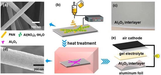
Figure 1.
Scanning Electron Microscope (SEM) images of the electrospun nanofibers before (a) and after (d) heat treatment. (b) Schematic showing the fabrication process of the Al2O3 interlayer. (c) The Al2O3 interlayer fabricated by electrospinning. (e) Sandwich structure of the Al–air battery.
2.3. Characterization and Electrochemical Tests
The morphology of the samples was characterized by SEM (Su-8010, Hitachi, Tokyo, Japan). The crystalline structures of the samples were characterized using an XRD instrument (Bruker D8 Advance, Bruker Corp., Billerica, MA, USA) with a Cu kα radiation of 0.1541 nm as an X-ray source. The thickness of the Al2O3 interlayer was measured by Dektak XT (Bruker, Karlsruhe, Germany) profile meter.
The polymer alkaline gel electrolyte and flexible air cathode were prepared according to our previous paper [6,39], respectively. A 3 × 4 cm aluminum foil served as the metal anode. The solid Al–air battery was assembled as the sandwich type, as schematically illustrated in Figure 1e. The Al anode modified with an Al2O3 interlayer is shown in Figure 1c. In order to analyze the electrochemical performance of the Al anode with Al2O3 film, cyclic voltammetry was carried out at a scan rate of 100 mV/s from −1.9 to −0.5 V in 4 M KOH solution by the Metrohm Autolab. The constant current discharge was carried out using a battery testing system (CT2001A, LAND Electronics Co., Ltd., Wuhan, China). The electrochemical tests were carried out by an electrochemical workstation (RST5000, Shiruisi, Zhengzhou, China). An Hg/HgO and a platinum wire were used as reference and counter electrodes. Potentiodynamic polarization was measured at a scan rate of 1 mV/s. Electrochemical impedance spectroscopy (EIS) measurements were tested with an AC amplitude of 10 mV and frequency from 0.01 Hz to 100 kHz. All the electrochemical tests for every material were repeated at least three times to ensure reproducibility.
3. Results and Discussion
3.1. Characterization of the Al2O3 Interlayer
The surface morphology of the electrospun interlayer after heat treatment was investigated by SEM, as shown in Figure 2a. A perfect fibers formation characterized by a similar size of about 450 nm was observed for the samples, as shown in Figure 2b. A higher roughness degree (Figure 1d) after heat treatment was due to the decomposition of Al(NO3)3·9H2O along the nanofibers. In addition, PAN in the nanofibers could be decomposed and burned at 250 °C [40]. XRD patterns of the electrospun samples were reported in Figure 2c. A peak of 2θ = 17° was attributed to the (001) reflection of the orthorhombic PAN [41]; this is because PAN could not decompose completely until 700 °C [42]. Characteristic diffraction peaks of the Al2O3 phase at 2θ = 25.3°, 35.1°, 37.4°, 43.4°, 52.9°, 57.7°, 62.1°, 67.2°and 68.3° were observed in the pattern of the nanofibers representing the (012), (104), (110), (113), (024), (116), (122), (214) and (300) reflections, respectively. The observations were consistent with the reported dates (JCPDS Card 42-1468). No other peaks were observed for the film, suggesting better control over the chemistry of the Al2O3 film offered by electrospinning.

Figure 2.
(a) SEM image of the Al2O3 film. (b) The diameter distribution of the Al2O3 film. (c) XRD patterns of the Al2O3 nanofibers.
3.2. Electrochemical Characterization of Al-Air Batteries
The open-circuit potential (OCP) of Al anodes with different thickness Al2O3 films in 4 M KOH electrolyte is displayed in Figure 3a. Compared with a pure Al anode, the Al anode with thicker Al2O3 film has the more negative OCP in alkaline electrolyte solution. This indicates that the Al2O3 film can considerably shift the OCP negatively. The negative potential shift may be explained by the fact that the Al2O3 film protects the Al anode and alleviates the polarization reaction. To examine the effects of the protection of Al2O3 film on the Al anode, the Al anode with Al2O3 films was subjected to 1 h of OCP exposure in the electrolyte solution followed by 1 h of anodic polarization under a current density of 5 mA/cm2. Figure 3b shows the potential transient of the Al anode recorded during four continuous cycles. The results show that the potential transient of Al anode with Al2O3 film is more stable during the cycling and has a better discharge performance than the pure Al anode, especially for the case of 6 μm Al2O3 film.
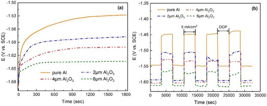
Figure 3.
(a) Open-circuit potential (OCP) curves of Al anodes without and with different thicknesses of Al2O3 films in 4 M KOH. (b) Potential-time transients recorded for Al anodes without and with different thicknesses of Al2O3 films during 4 cycles (consisting of 1 h rest period at OCP and 1 h discharge at a current density of 5 mA/cm2) in 4 M KOH.
Figure 4 shows the cyclic voltammograms of Al anodes with different thicknesses of Al2O3 films from −1.9 to −0.5 V at a scan rate of 100 mV/s in 4 M KOH solution. The anodic peaks A and B for pure Al are at −1.13 and −1.06 V vs. Hg/HgO. The cyclic voltammogram of the Al anode with an Al2O3 film displays that the peak A and B shifted positively, and the peaks shift more significantly in the positive direction with the increasing thickness of the Al2O3 film. The peak A in the anodic sweep is due to the oxidation of Al to Al(OH)4−, and peak B in the cathodic sweep is due to the dissolution of the passivated film of Al(OH)3. The Al anode is more difficult to oxidize when protected by the Al2O3 film, which would result in less hydrogen evolution and reduced corrosion. In addition, the voltage separation between peaks A and B changes little in the four curves, indicating that the redox behavior is almost the same.
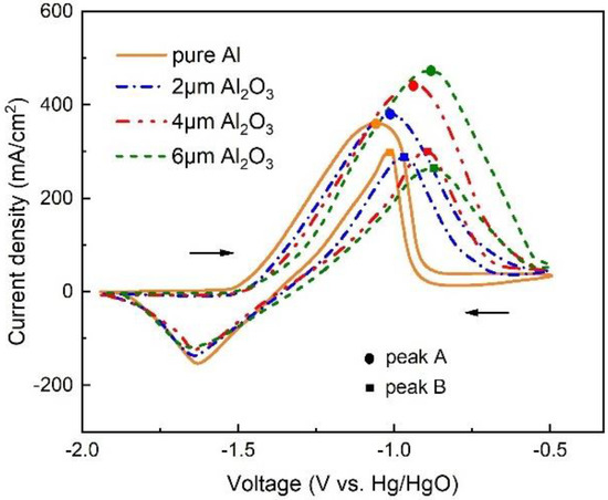
Figure 4.
Cyclic voltammogram of Al anode without and with different thicknesses of Al2O3 films in 4 M KOH.
In order to understand the effect of the Al2O3 interlayer thickness, the electrochemical impedance spectroscopy of the Al-air batteries with different thicknesses of Al2O3 interlayers are given in Figure 5. A typical Nyquist plot of a single-cell practical Al–air battery is composed of two semicircles that correspond to different battery process, described by an equivalent circuit with five elements [43] (Figure 5 inset), namely solution resistance (), solid/electrolyte interface (), charge transfer resistance during electrochemical process (), and two constant phase elements ( and ). The fitting parameters of the different components of the samples are summarized in Table 1. The solution resistance Rs increases with the thickness of Al2O3 interlayer, which indicates that the electrolyte resistivity increases and the diffusion of ions becomes more and more difficult [43]. is also much higher than the pure Al anode; this is because the Al2O3 interlayer hinders direct contact between the electrolyte and the electrode. The is used to indicate the degree of ease of reaction with the metal when the electrolyte reaches the anode surface. The larger the charge transfer resistance , the more difficult it is to react. Compared with pure Al, the value of the coating capacitance decreases by more than two orders of magnitude, reaching 2.69 × 10⁻⁷ F with 6 μm Al2O3. In addition, the double layer capacitance decreases as the thickness of Al2O3 interlayer increases, which is related to the porosity of the Al2O3 interlayer. directly corresponds to the exposed surface area of the electrode [44]. The thicker Al2O3 interlayers have less porosity and better protection for the Al anode. Similar conclusions have also been obtained in the research of Díaz et al. [45]. It can be seen that and increase in the following order: pure Al < Al with 2 μm Al2O3 interlayer < Al with 4 μm Al2O3 interlayer < Al with 6 μm Al2O3 interlayer, indicating that the coating of an Al2O3 interlayer on the Al anode can effectively improve corrosion resistance.
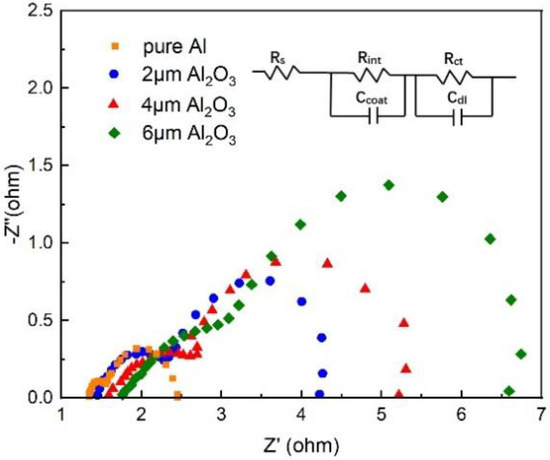
Figure 5.
Nyquist plots of the Al anode modified by Al2O3 interlayers of different thickness.

Table 1.
The resistance values of the equivalent circuit elements based on electrochemical impedance spectroscopy (EIS) measurements of Al–air batteries (The % errors are mentioned with circuit elements).
To further confirm the corrosion resistance of the Al2O3 interlayer, Figure 6 and Table 2 indicate the Tafel curves and the related corrosion parameters of pure Al and the Al anode modified with different thicknesses of Al2O3 interlayers in the 4 M KOH electrolyte, respectively. Parameter is the protection efficiency and is obtained by the following equation [46]
where and are the corrosion current densities without and with the Al2O3 interlayer in KOH solution. Compared to the pure Al anode, after the modification of the Al2O3 interlayer, the Tafel slopes of the cathode and anode both decreased. The results showed that the Al2O3 interlayer improved the anticorrosion performance of the Al anode. As can be seen in Figure 6, the variation in the self-corrosion potential was little, indicating that the performance of anticorrosion works by the geometrical coverage effect [47]. In addition, after modifying the anode with an Al2O3 interlayer, the polarization curves of the anode and cathode were almost parallel, suggesting that the modification of the Al2O3 interlayer did not change the reaction mechanism. The protection efficiency increased with the Al2O3 interlayer thickness. The of the Al with 6 μm Al2O3 interlayer (61.3 μA/cm2) is much more smaller than that of pure Al (427.5 μA/cm2), and reached 85.66%.
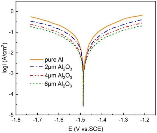
Figure 6.
Potentiodynamic polarization curves of the Al anode modified by Al2O3 interlayers of different thickness.

Table 2.
Corrosion parameters from polarization curves (the % errors are mentioned with the corrosion parameters).
The electrochemical performance of the Al–air battery was investigated by recording polarization and power density curves with different thickness Al2O3 interlayers, as shown in Figure 7a,b. The Al–air battery with an Al2O3 interlayer (2 and 4 μm) behaves similarly to the pure Al at a low current region (0.1–5 mA/cm2). However, the power density and the voltage decreased significantly compared with the batteries using a pure Al anode at a high current region, indicating a significant hydroxyl shortage. This is because the Al2O3 interlayer effectively inhibits the direct contact between the electrolyte and the anode. The thin interlayer hinders the transport of hydroxide ions, leading to a decrease in conductivity of the electrolyte compared to the free electrolyte without the Al2O3 interlayer. It is worth noting that the Al–air battery with a 4 μm Al2O3 interlayer has a current reverse at a high current region. This phenomenon is much more obvious in the case of the 6 μm Al2O3 interlayer. When increasing the thickness of the Al2O3 interlayer, the battery performance gradually decreases, which is mainly due to the reduced electrolyte conductivity. The mass transport loss is also gradually aggravated, indicating that hydroxide ion concentration plays an important role in supporting a high discharge current density. The battery encounters a server mass transport loss at a high current density, but the corrosion of the Al anode is inhibited at the same time. The Al–air battery with an Al2O3 interlayer suppresses Al corrosion by sacrificing its high current density output in this manner. The Al2O3 interlayer thickness could affect the battery performance by two aspects. On the one hand, a thicker Al2O3 interlayer could better suppress anode corrosion, but it is unable to provide enough hydroxide ions. On the other hand, a thinner Al2O3 interlayer could lead to a lower ionic resistance, but the effect of inhibiting corrosion may be limited. In order to explore the effect of Al2O3 interlayer thicknesses on the battery characteristics, we have studied a single-cell anode and cathode polarization curves, as shown in Figure 7c. It can be seen that the cathode curves remained identical, while there were significant differences in the anode curves. The two polarization curves for 2 and 4 μm Al2O3 interlayers are likely the same at the low current region. This is because a lower concentration of hydroxide ions can meet the need of discharge. However, a 6 μm Al2O3 interlayer seriously affects the charge transfer, even at a low current region. At a high current density region, the phenomenon of hydroxyl starvation becomes more and more obvious as the thickness of the Al2O3 interlayer increases. This illustrates that the Al–air battery with Al2O3 interlayer is more suitable for a low current density discharge.

Figure 7.
Polarization curves (a) and power density plots (b) of the Al–air battery modified by Al2O3 interlayers of different thicknesses. (c) Single-cell anode and cathode polarization of the Al–air batteries modified by Al2O3 interlayers with different thicknesses.
Figure 8 shows the discharge behavior of the Al–air battery with different thicknesses of Al2O3 interlayers at low current densities (1, 3 and 5 mA/cm2). From the polarization curves in Figure 7a, the Al–air battery with 6 μm Al2O3 interlayer could only achieve a lower voltage even at a low current density. Therefore, the discharge performance in the case of 6 μm Al2O3 interlayer is not considered in the test. As shown in Figure 8a–c, the Al–air battery with an Al2O3 interlayer showed a longer discharge time than pure Al. The improved sustainability of the Al anode is due to the suppression of corrosion. The Al–air battery with a 4 μm Al2O3 interlayer has the longest discharge time. Only 0.016 g Al with a 4 μm Al2O3 interlayer as an anode could sustain a current density of 1 mA/cm2 for 10.6 h, 3 mA/cm2 for 5.75 h, and 5 mA/cm2 for 4.16 h. The discharge voltage changes little compared to pure Al anode and is better sustained at all three current densities, indicating that the hydroxyl ions are enough to support such current densities. The battery finally encounters an instant drop in voltage because the amount of Al is exhausted at the end of the discharge process. In order to investigate stability during the discharge process, the rate discharge performance of Al–air batteries with different thicknesses of Al2O3 interlayers at different current densities are compared in Figure 8d. The Al–air battery with an Al2O3 interlayer exhibits significantly stable output voltage within current densities ranging from 1 to 5 mA/cm2. Within the range, the discharge voltage plateaus of Al–air batteries with 2 and 4 μm Al2O3 interlayers vary little compared with the Al–air battery at the same current density. The stable discharge performance can be attributed to that fact that the hydroxide ions provided by the electrolyte are sufficient for the anodic reaction, even if some of the hydroxide ions have been blocked by the Al2O3 interlayer. By increasing the current density to 10 mA/cm2, the discharge voltage of Al-air batteries with Al2O3 interlayer decreases significantly, especially for the case of the 4 μm Al2O3 interlayer, indicating that the hydroxide ions are not enough to meet such a large current discharge. This further illustrates that the Al–air batteries with an Al2O3 interlayer are more suitable for a low-current discharge.
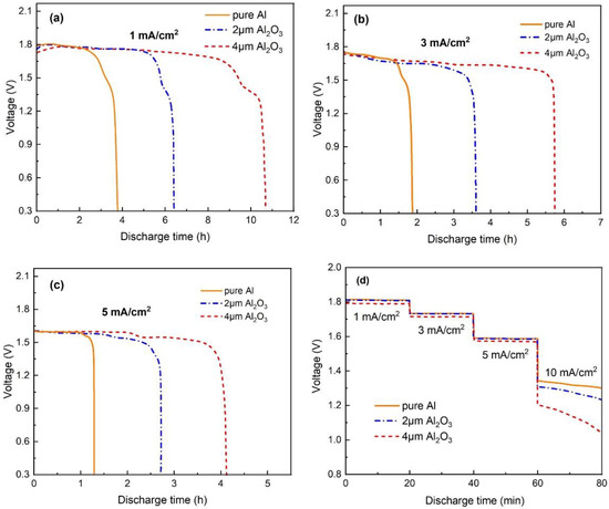
Figure 8.
Discharge curves of the Al–air batteries modified by Al2O3 interlayers with different thicknesses at (a) 1, (b) 3, (c) 5 mA/cm2 and (d) rate discharge.
Furthermore, Figure 9a,b summarize the corresponding discharge time and capacities of the Al-air batteries. It is apparent that the solid Al–air battery with a 4 μm Al2O3 interlayer is more appropriate to work at low current densities in order to achieve better utilization of the Al anode. The highest specific capacity of 1255 mAh/g is achieved with a 4 μm Al2O3 interlayer at 5 mA/cm2. This value is still better than those of a conventional Al–air battery with a high-purity Al anode in both gelled [13] and liquid electrolyte [48]. Due to the limited contact of electrolyte and anode, together with the porous structure of Al2O3 interlayer, the amount of hydroxide ions and their diffusion to the Al anode is greatly suppressed. The high utilization of the Al anode is due to the special transfer of hydroxide ions.
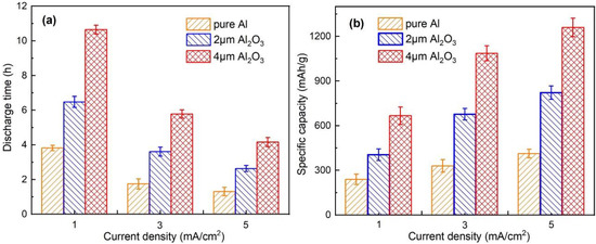
Figure 9.
(a) Discharge time and (b) specific capacities of the Al–air batteries modified by an Al2O3 interlayer with different thicknesses at different current densities.
4. Conclusions
The present study aims to examine the impact of an Al2O3 interlayer on anodic corrosion in a solid Al–air battery. The Al2O3 interlayer was fabricated through electrospinning on the surface of the Al anode. SEM and XRD measurements confirmed the porous structure and composition of the electrospun interlayer. Electrochemical tests were performed to investigate the efficiency of the Al2O3 interlayer and battery performance. It was established that the Al2O3 interlayer had a significant effect on Al corrosion. The results showed that the Al–air battery with an Al2O3 interlayer is more suitable for low current density discharges. The batteries could be applied for mini-watt devices with a low current requirement, such as portable electronics and biosensors. It achieves the purpose of suppressing anode corrosion by sacrificing high current output. In addition, the effect of the Al2O3 interlayer thickness on corrosion resistance. As the Al2O3 interlayer thickness increases, the corrosion resistance increases, but the transport of hydroxide ions is also suppressed. Discharge experiments showed that an Al–air battery with a Al2O3 interlayer provided an excellent stability and a significantly high capacity. The specific capacities of the Al-air battery with 2 and 4 μm Al2O3 interlayers are 816 ± 24 and 1255 ± 33 mAh/g at 5 mA/cm2, which is much more than pure Al anode (416 ± 35 mAh/g). Generally, the addition of an Al2O3 interlayer on the surface of an anode can suppress the anodic corrosion, thus improving the capacity of the Al–air battery. The electrospun Al2O3 interlayer for a solid Al–air battery is very promising for the mini-watt electronics.
Author Contributions
Conceptualization, C.Z.; methodology, Y.Y.; investigation, H.L.; data curation, Z.G. and Q.C.; writing—original draft preparation, Y.Z.; writing—review and editing, Y.Z.; supervision, C.Z. All authors have read and agreed to the published version of the manuscript.
Funding
This research was funded by the National Natural Science Foundation of China, grant number 11802102 and 51775242, and the Natural Science Foundation of Zhejiang Provincial, grant number LQ20E040007 and LY19A020006.
Conflicts of Interest
The authors declare no conflict of interest.
References
- Can, Y.S.; Arnrich, B.; Ersoy, C. Stress detection in daily life scenarios using smart phones and wearable sensors: A survey. J. Biomed. Inform. 2019, 92, 103139. [Google Scholar] [CrossRef] [PubMed]
- Jayathilaka, W.A.D.M.; Qi, K.; Qin, Y.; Chinnappan, A.; Serrano-García, W.; Baskar, C.; Wang, H.; He, J.; Cui, S.; Thomas, S.W.; et al. Significance of Nanomaterials in Wearables: A Review on Wearable Actuators and Sensors. Adv. Mater. 2019, 31, 1805921. [Google Scholar] [CrossRef] [PubMed]
- Wang, C.; Xia, K.; Wang, H.; Liang, X.; Yin, Z.; Zhang, Y. Advanced Carbon for Flexible and Wearable Electronics. Adv. Mater. 2019, 31, 1801072. [Google Scholar] [CrossRef] [PubMed]
- Huang, S.; Liu, Y.; Zhao, Y.; Ren, Z.; Guo, C.F. Flexible Electronics: Stretchable Electrodes and Their Future. Adv. Funct. Mater. 2019, 29, 1805924. [Google Scholar] [CrossRef]
- Fan, L.; Wei, S.; Li, S.; Li, Q.; Lu, Y. Recent Progress of the Solid-State Electrolytes for High-Energy Metal-Based Batteries. Adv. Energy Mater. 2018, 8, 1702657. [Google Scholar] [CrossRef]
- Zhang, Z.; Zuo, C.; Liu, Z.; Yu, Y.; Zuo, Y.; Song, Y. All-solid-state Al-air batteries with polymer alkaline gel electrolyte. J. Power Source 2014, 251, 470–475. [Google Scholar] [CrossRef]
- Kim, T.; Song, W.; Son, D.Y.; Ono, L.K.; Qi, Y. Lithium-ion batteries: Outlook on present, future, and hybridized technologies. J. Mater. Chem. A 2019, 7, 2942–2964. [Google Scholar] [CrossRef]
- Voskanyan, A.A.; Ho, C.K.; Chan, K.Y. 3D Δ-MnO2 nanostructure with ultralarge mesopores as high-performance lithium-ion battery anode fabricated via colloidal solution combustion synthesis. J. Power Source 2019, 421, 162–168. [Google Scholar] [CrossRef]
- Wen, L.; Liang, J.; Chen, J.; Chu, Z.Y.; Cheng, H.M.; Li, F. Smart Materials and Design toward Safe and Durable Lithium Ion Batteries. Small Methods 2019, 3, 1900323. [Google Scholar] [CrossRef]
- Su, C.Y.; Cheng, H.; Li, W.; Liu, Z.Q.; Li, N.; Hou, Z.; Bai, F.Q.; Zhang, H.X.; Ma, T.Y. Atomic Modulation of FeCo–Nitrogen–Carbon Bifunctional Oxygen Electrodes for Rechargeable and Flexible All-Solid-State Zinc–Air Battery. Adv. Energy Mater. 2017, 7, 1602420. [Google Scholar] [CrossRef]
- Guan, C.; Sumboja, A.; Wu, H.; Ren, W.; Liu, X.; Zhang, H.; Liu, Z.; Cheng, C.; Pennycook, S.J.; Wang, J. Hollow Co3O4 Nanosphere Embedded in Carbon Arrays for Stable and Flexible Solid-State Zinc–Air Batteries. Adv. Mater. 2017, 29, 1704117. [Google Scholar] [CrossRef] [PubMed]
- Shen, J.; Meng, L.; Liu, Y.; Chen, C.; Zhu, Y.; Li, C. Preparation of Co-N carbon nanosheet oxygen electrode catalyst by controlled crystallization of cobalt salt precursors for all-solid-state Al-air battery. RSC Adv. 2018, 8, 22193–22198. [Google Scholar] [CrossRef]
- Xu, Y.; Zhao, Y.; Ren, J.; Zhang, Y.; Peng, H. An All-Solid-State Fiber-Shaped Aluminum–Air Battery with Flexibility, Stretchability, and High Electrochemical Performance. Angew. Chem. Int. Ed. 2016, 55, 7979–7982. [Google Scholar] [CrossRef]
- Ma, Y.; Sumboja, A.; Zang, W.; Yin, S.; Wang, S.; Pennycook, S.J.; Kou, Z.; Liu, Z.; Li, X.; Wang, J. Flexible and Wearable All-Solid-State Al-Air Battery Based on Iron Carbide Encapsulated in Electrospun Porous Carbon Nanofibers. ACS Appl. Mater. Interfaces 2019, 11, 1988–1995. [Google Scholar] [CrossRef] [PubMed]
- Zhao, X.; Li, X.; Gong, Y.; Huang, K. Enhanced reversibility and durability of a solid oxide Fe-air redox battery by carbothermic reaction derived energy storage materials. Chem. Commun. 2014, 50, 623–625. [Google Scholar] [CrossRef] [PubMed]
- Liu, Y.; Li, B.; Kitaura, H.; Zhang, X.; Han, M.; He, P.; Zhou, H. Fabrication and Performance of All-Solid-State Li-Air Battery with SWCNTs/LAGP Cathode. ACS Appl. Mater. Interfaces 2015, 7, 17307–17310. [Google Scholar] [CrossRef] [PubMed]
- Liu, Q.; Chang, Z.; Li, Z.; Zhang, X. Flexible Metal-Air Batteries: Progress, Challenges, and Perspectives. Small Methods 2018, 2, 1700231. [Google Scholar] [CrossRef]
- Di Palma, T.M.; Migliardini, F.; Caputo, D.; Corbo, P. Xanthan and κ-carrageenan based alkaline hydrogels as electrolytes for Al/air batteries. Carbohydr. Polym. 2017, 157, 122–127. [Google Scholar] [CrossRef]
- Pino, M.; Chacón, J.; Fatás, E.; Ocón, P. Performance of commercial aluminium alloys as anodes in gelled electrolyte aluminium-air batteries. J. Power Source 2015, 299, 195–201. [Google Scholar] [CrossRef]
- Tan, M.J.; Li, B.; Chee, P.; Ge, X.; Liu, Z.; Zong, Y.; Loh, X.J. Acrylamide-derived freestanding polymer gel electrolyte for flexible metal-air batteries. J. Power Source 2018, 400, 566–571. [Google Scholar] [CrossRef]
- Deyab, M.A. Effect of nonionic surfactant as an electrolyte additive on the performance of aluminum-air battery. J. Power Source 2019, 412, 520–526. [Google Scholar] [CrossRef]
- Hong, Q.; Lu, H.; Cao, Y. Improved oxygen reduction activity and stability on N, S-enriched hierarchical carbon architectures with decorating core-shell iron group metal sulphides nanoparticles for Al-air batteries. Carbon 2019, 145, 53–60. [Google Scholar] [CrossRef]
- Kang, Q.X.; Zhang, T.Y.; Wang, X.; Wang, Y.; Zhang, X.Y. Effect of cerium acetate and L-glutamic acid as hybrid electrolyte additives on the performance of Al–air battery. J. Power Source 2019, 443, 227251. [Google Scholar] [CrossRef]
- Eftekhari, A.; Corrochano, P. Electrochemical energy storage by aluminum as a lightweight and cheap anode/charge carrier. Sustain. Energy Fuels 2017, 1, 1246–1264. [Google Scholar] [CrossRef]
- Liang, R.; Su, Y.; Sui, X.; Gu, D.; Huang, G.; Wang, Z. Effect of Mg content on discharge behavior of Al-0.05Ga-0.05Sn-0.05Pb-xMg alloy anode for aluminum-air battery. J. Solid State Electrochem. 2019, 23, 53–62. [Google Scholar] [CrossRef]
- Ren, J.; Ma, J.; Zhang, J.; Fu, C.; Sun, B. Electrochemical performance of pure Al, Al–Sn, Al–Mg and Al–Mg–Sn anodes for Al-air batteries. J. Alloys Compd. 2019, 808, 151708. [Google Scholar] [CrossRef]
- Mutlu, R.N.; Ateş, S.; Yazıcı, B. Al-6013-T6 and Al-7075-T7351 alloy anodes for aluminium-air battery. Int. J. Hydrog. Energy 2017, 42, 23315–23325. [Google Scholar] [CrossRef]
- Hopkins, B.J.; Shao-horn, Y.; Hart, D.P. Suppressing corrosion in primary aluminum–air batteries via oil displacement. Science 2018, 362, 658–661. [Google Scholar] [CrossRef]
- Amiinu, I.S.; Pu, Z.; Liu, X.; Owusu, K.A.; Monestel, H.G.R.; Boakye, F.O.; Zhang, H.; Mu, S. Multifunctional Mo–N/C@MoS2 Electrocatalysts for HER, OER, ORR, and Zn–Air Batteries. Adv. Funct. Mater. 2017, 27, 1702300. [Google Scholar] [CrossRef]
- Nie, Y.; Gao, J.; Wang, E.; Jiang, L.; An, L.; Wang, X. An effective hybrid organic/inorganic inhibitor for alkaline aluminum-air fuel cells. Electrochim. Acta 2017, 248, 478–485. [Google Scholar] [CrossRef]
- Popoola, L.T. Organic green corrosion inhibitors (OGCIs): A critical review. Corros. Rev. 2019, 37, 71–102. [Google Scholar] [CrossRef]
- Lv, Y.; Wang, L.; Li, Y.; Jin, Y.; Feng, J.; ming Ren, Y.; Cao, D.; Wang, G.; Zhang, M. The effect of different concentrations of Na2SnO3 on the electrochemical behaviors of the Mg-8Li electrode. Ionics 2014, 20, 1573–1578. [Google Scholar] [CrossRef]
- Mutlu, R.N.; Yazıcı, B. Copper-deposited aluminum anode for aluminum-air battery. J. Solid State Electrochem. 2019, 23, 529–541. [Google Scholar] [CrossRef]
- Jo, Y.N.; Kang, S.H.; Prasanna, K.; Eom, S.W.; Lee, C.W. Shield effect of polyaniline between zinc active material and aqueous electrolyte in zinc-air batteries. Appl. Surf. Sci. 2017, 422, 406–412. [Google Scholar] [CrossRef]
- Lu, Y.; Xiao, X.; Cao, Z.; Zhan, Y.; Cheng, H.; Xu, G. Transparent optically vanadium dioxide thermochromic smart film fabricated via electrospinning technique. Appl. Surf. Sci. 2017, 425, 233–240. [Google Scholar] [CrossRef]
- Chen, J.Y.; Wu, H.C.; Chiu, Y.C.; Chen, W.C. Plasmon-enhanced polymer photovoltaic device performance using different patterned Ag/PVP electrospun nanofibers. Adv. Energy Mater. 2014, 4, 1301665. [Google Scholar] [CrossRef]
- Lee, S.M.; Kim, Y.J.; Eom, S.W.; Choi, N.S.; Kim, K.W.; Cho, S.B. Improvement in self-discharge of Zn anode by applying surface modification for Zn-air batteries with high energy density. J. Power Source 2013, 227, 177–184. [Google Scholar] [CrossRef]
- Wongrujipairoj, K.; Poolnapol, L.; Arpornwichanop, A.; Suren, S.; Kheawhom, S. Suppression of zinc anode corrosion for printed flexible zinc-air battery. Phys. Status Solidi B 2017, 254, 1600442. [Google Scholar] [CrossRef]
- Yu, Y.; Zuo, Y.; Liu, Y.; Wu, Y.; Zhang, Z.; Cao, Q.; Zuo, C. Directly Electrospun Carbon Nanofibers Incorporated with Mn 3 O 4 Nanoparticles as Bending-Resistant Cathode for Flexible Al-Air Batteries. Nanomaterials 2020, 10, 216. [Google Scholar] [CrossRef]
- Horrocks, A.R.; Zhang, J.; Hall, M.E. Flammability of polyacrylonitrile and its copolymers II. Thermal behaviour and mechanism of degradation. Polym. Int. 1994, 33, 303–314. [Google Scholar] [CrossRef]
- Zhang, Z.; Zhang, L.; Wang, S.; Chen, W.; Lei, Y. A convenient route to polyacrylonitrile/silver nanoparticle composite by simultaneous polymerization-reduction approach. Polymer 2001, 42, 8315–8318. [Google Scholar] [CrossRef]
- Peng, C.; Zhang, J.; Xiong, Z.; Zhao, B.; Liu, P. Fabrication of porous hollow γ-Al2O3 nanofibers by facile electrospinning and its application for water remediation. Microporous Mesoporous Mater. 2015, 215, 133–142. [Google Scholar] [CrossRef]
- Ahmad, H.M.N.; Ghosh, S.; Dutta, G.; Maddaus, A.G.; Tsavalas, J.G.; Hollen, S.; Song, E. Effects of Impurities on the Electrochemical Characterization of Liquid-Phase Exfoliated Niobium Diselenide Nanosheets. J. Phys. Chem. C 2019, 123, 8671–8680. [Google Scholar] [CrossRef]
- Vogelsang, J.; Strunz, W. The evaluation of experimental dielectric data of barrier coatings by means of different models. Electrochim. Acta 2001, 46, 3619–3625. [Google Scholar]
- Díaz, B.; Härkönen, E.; Światowska, J.; Maurice, V.; Seyeux, A.; Marcus, P.; Ritala, M. Low-temperature atomic layer deposition of Al2O3 thin coatings for corrosion protection of steel: Surface and electrochemical analysis. Corros. Sci. 2011, 53, 2168–2175. [Google Scholar] [CrossRef]
- Zhu, H.; Yue, L.; Zhuang, C.; Zhang, Y.; Liu, X.; Yin, Y.; Chen, S. Fabrication and characterization of self-assembled graphene oxide/silane coatings for corrosion resistance. Surf. Coat. Technol. 2016, 304, 76–84. [Google Scholar] [CrossRef]
- Liu, J.; Wang, D.; Gao, L.; Zhang, D. Synergism between cerium nitrate and sodium dodecylbenzenesulfonate on corrosion of AA5052 aluminium alloy in 3 wt.% NaCl solution. Appl. Surf. Sci. 2016, 389, 369–377. [Google Scholar] [CrossRef]
- Liu, Y.; Li, J.; Li, W.; Li, Y.; Zhan, F.; Tang, H.; Chen, Q. Exploring the nitrogen species of nitrogen doped graphene as electrocatalysts for oxygen reduction reaction in Al-air batteries. Int. J. Hydrog. Energy 2016, 41, 10354–10365. [Google Scholar] [CrossRef]
© 2020 by the authors. Licensee MDPI, Basel, Switzerland. This article is an open access article distributed under the terms and conditions of the Creative Commons Attribution (CC BY) license (http://creativecommons.org/licenses/by/4.0/).