1. Introduction
Understanding technological growth and development is vital for societal progress. The technology life-cycle (TLC) defines the timeline of a manufacturing process, from its conception to culmination. Its first major step is the “research and development phase”, which entails high risk of failure and that shall be completed before moving to an ascendant phase of commercialization [
1]. To evaluate state-of-progress during the R&D phase, another tool, known as the technology readiness level (TRL) scale, is introduced.
Developed by the National Aeronautics and Space Administration (NASA), the TRL scale is currently employed to evaluate the maturity of a given technology during an innovation process, summarizing its risks and opportunities. In recent years, the TRL scale has been adopted by the European Union to evaluate the funding of project proposals by classifying different research stages in nine progressive levels [
2]. These evolve from the observation of basic principles (TRL1) and Technology concept formulated (TRL2) up to “system proven in operational environment” (TRL 9), passing through several steps including fabrication and validation of prototypes in relevant environments.
During the conception of research & development proposals, the objective is to progress from a low TRL to, at least, the following level. For example, experimental science often targets to create a proof of concept that can be later validated in industrial conditions with the goal of transferring the technology from the research institution or facilities to a commercializing process or business. In that way, it is possible to validate the impact and potential application of the project to society.
In the case of research focused on energy storage, recent advances in material science have led to novel energy storage materials and technologies. These can potentially have a major impact on one of the seventeen most important goals for sustainable development, as stated by the United Nations [
3], “Ensure access to affordable, reliable, sustainable and modern energy”. During the last decade, research has focused intensively in producing novel materials with enhanced properties to improve the current state-of-the art electrochemical energy storage devices; from lithium-batteries to ultracapacitors [
4]. Lithium-ion batteries are, to the date, the most efficient and commercialized energy storage devices. Nonetheless, technological developments impose energy storage requirements that Li-ion batteries cannot meet [
5]. Alternative technologies are, therefore, under investigation; from lithium-air batteries [
6] to aluminum-ion batteries [
7]. The present case study reports some of the challenges faced, at an experimental level, during the development of a potentially scalable hybrid capacitor prototype.
Hybrid capacitor devices have been explored to bridge the gap between the high-power capabilities of electrical double-layer capacitors and the high-energy density of batteries. To that end, they integrate a capacitive electrode, usually carbon-based, that ensures high-power density and cycling stability and a battery-like material, based on metal compounds (typically oxides or hydroxides), that increase the overall energy that can be stored in the device. The different performance of the constituent electrodes is a consequence of their different energy storing nature, while the former is based on electrostatic adsorption/desorption of ions at the electrode-electrolyte interface; the latter relies on faradaic processes that store energy by means of chemical reactions [
8].
In an effort to scale-up the production of a hybrid energy storage prototype, the present case study reports the assembly of a hybrid device to power a 12 W solar-powered LED lamp, with the consequent challenges and limitations faced. This contribution will guide the readers across the difficult art of developing a bench-scale prototype, starting from the preparation of the material and testing of the device to meeting the requirements of the final application.
2. Device Conceptualization
2.1. Material Selection
The first aspect to consider when building an energy storage prototype is the active material selection for both electrodes, positive and negative, as this will determine the device electrochemical response, device performance stability, shelf life and overall metrics. An adequate choice of materials for the electrodes must consider materials with good electrochemical performance and well-matched properties, active in the same electrolyte and that can be produced in large scale at an affordable price. Concomitantly, the selection of the electrolyte, preferably an environmentally friendly one, is a critical parameter and must be considered in the selection of the active materials. The recent trends highlight a shift towards aqueous and “greener” electrolytes that can replace conventional organic electrolytes that possess certain toxicity and have lower tolerance to high environmental temperature. Altogether, both materials and electrolyte must be synergistically combined. Therefore, for the targeted application, a solar powered LED light, an aqueous electrolyte will lead to less risks of explosion, more material availability, lower cost and environmental sustainability.
A hybrid device requires a battery-like and an electrical double layer capacitive-type (EDLC) electrode. Material production is limited by performance, production rate, and easy scale-up production. The materials selected for this case study are nickel-cobalt hydroxide, synthetized at the laboratory, and commercial activated carbon. While the former ensures the energy metrics, the latter determines the power capabilities. These two materials, apart from fulfilling the imposed electrochemical requirements, have been recently explored in literature as excellent energy storage materials [
9]. In fact, they are two of the most investigated materials and have been reported as two of the better performing materials known to the date. In addition, both are active in alkaline media, such as KOH 6M, which is used as electrolyte; they can be easily synthesized by scalable processes; they present acceptable cycling stability and its combination complies with the high-power imposed requirements.
An important aspect when using a laboratory-produced material is the scale-up. To ensure high-yield production, nickel-cobalt hydroxide was produced by co-precipitation. Therefore, the first constraint to be noted is the synthesis being limited by reactor sizes, reaction times and need of additional steps for separation and purification. This issue must be evaluated when planning the construction of a prototype and, it is crucial to consider that scale-up may affect the material properties (e.g., crystalline structure, morphology, composition, etc.), consequently having an impact on the final electrochemical response.
The proposed materials for the electrode assembly are available in powder form. Thus, an ink must be prepared and coated on top of a conductive substrate. Active material inks can be easily prepared under standard conditions [
10], this is, 10% conductive carbon (CB), 5% PVDF and 85% active material dispersed in N-Methyl-2-Pyrrolidone (NMP) for nickel-cobalt hydroxide and 5% CB, 5% PVDF and 90% activated carbon dispersed in the same solvent for the negative electrode. When introducing these additives, two important constraints are introduced: on the one hand, non-active mass and, on the other hand, poorly conductive species that may affect the electrode capacity.
A hybrid energy storage device typically targets good energy density and excellent power performance. For that reason, it is important to combine capacitive and faradaic materials that can act synergistically. For that matter, a carbon-based substrate may serve as excellent conductive matrix to enhance faradaic phenomena. Moreover, it ensures high surface roughness, good electrolyte penetrability, and high electronic conductivity and can introduce relevant capacitance contribution while maintaining high-power capabilities. Moreover, it presents low density, a key parameter in the final weight of the device. For these reasons, Toray carbon paper has been selected as conductive substrate for both the positive and negative electrodes. At this point is worth noting that the electronic conductivity and mechanical integrity of these substrates must be ensured over the entire assembling process.
Finally, an adequate separator with chemical stability in the designated electrolyte must be used. To that end, commercially available cellulose-based separators can be used. However, certain separators may entail stability problems under certain conditions. For example, certain polyamide separators may decompose under a highly alkaline media that may release ammoniacal gases. Adequate separator thickness shall also be considered. Excessive thickness may lead to increased resistance and, consequently, lower power and energy density response of the device. For that reason, a 0.12 mm thick polyolefin-based separator 700/39K was used since it is very stable in the very alkaline conditions created by the electrolyte. At this point, it is worth pointing out that a detailed assessment of the separator stability is a crucial step in the assembling of the device.
2.2. Definition of Cell Geometry
Considering that the ultimate objective is to create a 12 V battery that can power a 12 W LED streetlamp for twelve hours, it is crucial to define the capacity of the device. To that end, an approximately 15 A·h capacity battery would be required. However, the geometrical constraints of the lamp limit the battery dimensions to 27 cm × 15 cm × 3.2 cm, restricting the device geometry and number of stacks that can be assembled in series (to meet voltage targets) and in parallel to ensure the required capacity.
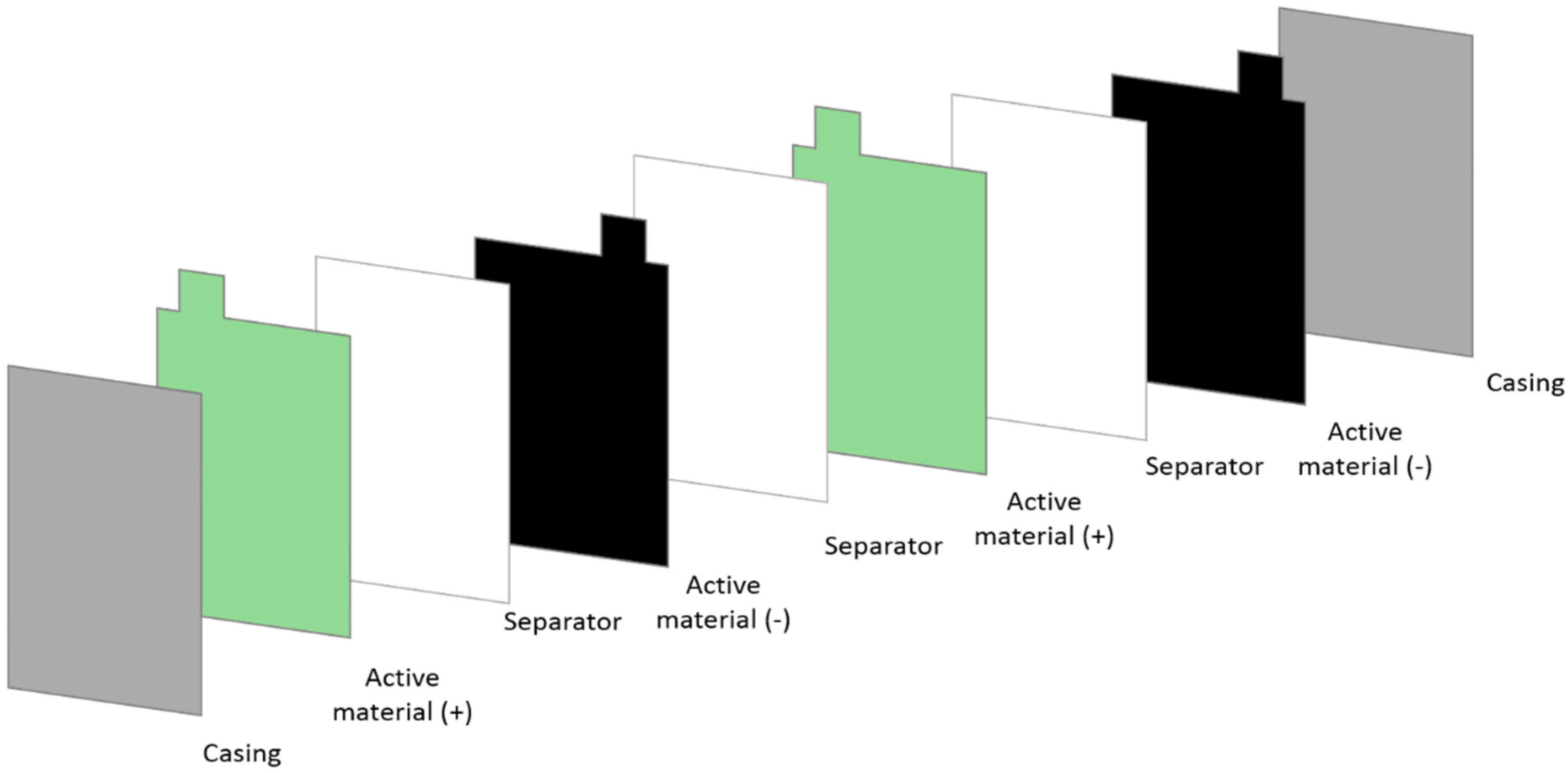
Since the objective is to deliver a prototype tailored to meet the application constraints, and because there are no available commercial cases, ideally, a pouch cell, as the one displayed in
Figure 1, adapted to the said dimensions could be used. However, the development of the casing requires additional design, developments and optimization to avoid electrolyte leakage, in addition to special equipment and accessories to assemble the casing parts. In this instance, a specially designed battery casing would be required for the specific application, but it is not available at a commercial scale. Moreover, this casing would entail preparing electrodes with an approximate dimension of 28 cm × 14 cm. The effect of such geometry raises another main challenge to bench-scale production: the amount of active material required to cover the conductive substrate would require dedicated laboratory facilities. Furthermore, ensuring that the basic material properties are not altered by scaling up is critical, as this process would greatly impact the final device metrics and, therefore, the number of stacks that would be required to meet capacity and voltage specifications.
Also, dedicated equipment must be used to measure the electrochemical response of the device. It is important to note that the measuring equipment must reach the intended voltage and current ranges. For example, regular potentiostats are limited to the ±5 A and ±6 V range, thus suitable equipment must be available. Therefore, developing a tailored casing, purchasing the adequate measuring equipment and producing enough active material to assemble the electrodes may consume significant time and must be considered during the planning of the first iteration to produce a prototype. In this specific example and because of the above-mentioned constraints, it was decided to assemble a small device for which the amount of material and existence of commercial casing was ensured. Thus, it was decided to base the prototype on coin cells.
These are commercially available, thus accessible, and can also be easily coupled in series (to increase the operating voltage) and parallel (to increase the output current). To that end, stainless-steel R2032 cells were selected, since they comprise all the desired requirements: commercially accessible, the amount of material introduced leads to a current range that falls within the measurable range of current and potential and the required active material is compatible with the scalability of the synthesis procedure at a bench scale. It is a good starting point to ground the assembling of small prototypes and to identify the constraints raised by the scale-up.
3. Electrochemical Performance of Individual Electrodes
3.1. Electrochemical Performance of Positive Electrode
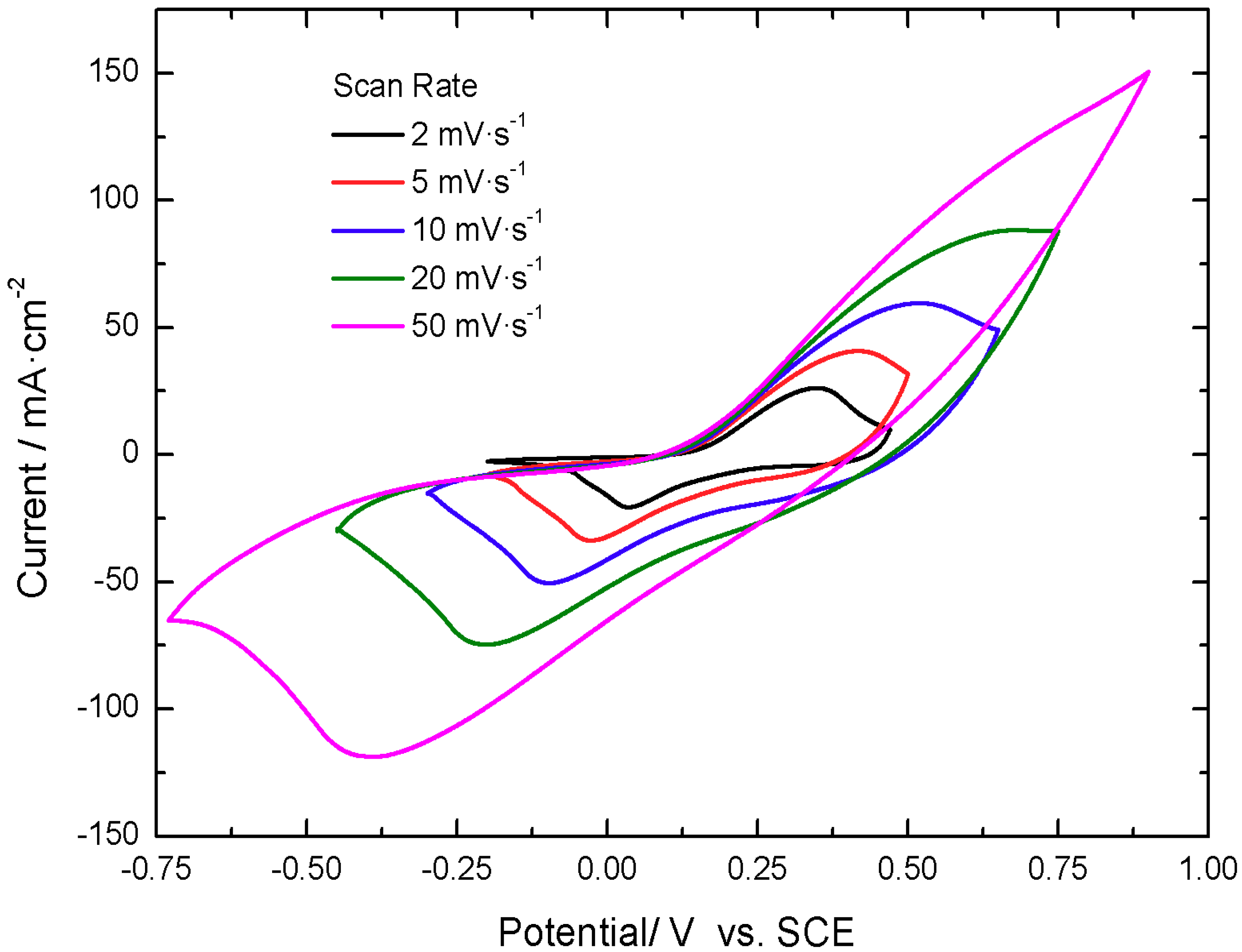
The active material for the positive electrode presents activity in the positive potential range vs. a saturated calomel electrode (SCE), displaying voltammograms with two quasi-reversible redox peaks, located at 0.35 V and 0.00 V vs. SCE at 5 mV·s
−1, as shown in
Figure 2. The peaks are displaced with increasing scan rate, as expected for a faradaic dominated electrochemical response.
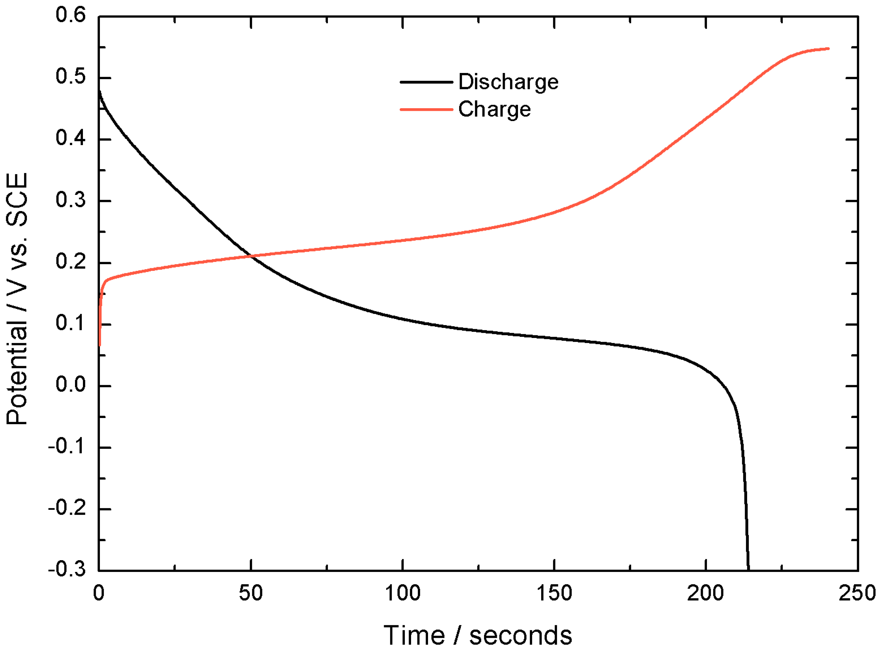
The capacity of this active material, when tested in a 3 electrodes electrochemical cell is 2.21 C cm
−2 at 10 mA cm
−2 with 92% Coulombic efficiency (100·discharge time/charge time), as shown in
Figure 3.
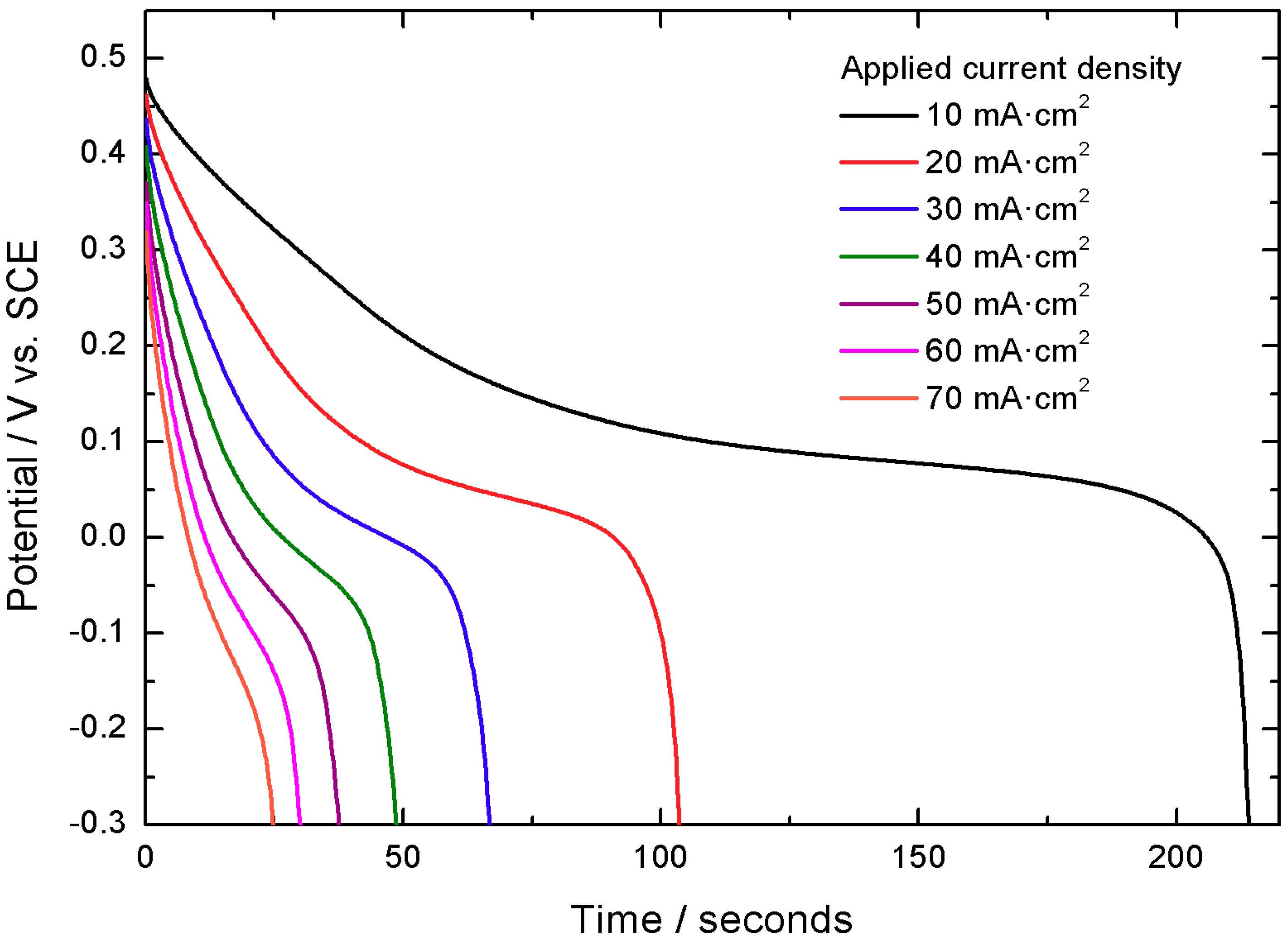
The capacity values obtained at different applied currents have been 2.08 C cm
−2 at 20 mA cm
−2, 2.02 C cm
−2 at 30 mA cm
−2, 1.98 C cm
−2 at 40 mA cm
−2, 1.93 C cm
−2 at 50 mA cm
−2, 1.87 C cm
−2 at 60 mA cm
−2 and 1.80 C cm
−2 at 70 mA cm
−2. These results, calculated during the third discharge curve in the −0.3 V to 0.5 V voltage range, exemplify the capacity retention properties of the material, retaining up to 82% of the initial capacity when the applied current density is increased seven times. This is exemplified in
Figure 4 and
Figure 5.
Finally, when the cycling stability of the material is evaluated, 78% of the initial capacity is retained after 2000 cycles at 100 mA cm
−2 in the −0.3 V to 0.5 V vs. SCE interval, as shown in
Figure 6, which is an important achievement for this type of material.
In conclusion, these results pinpoint the excellent performance of nickel-cobalt hydroxide on top of carbon paper as potential positive electrode for a hybrid energy storage device. Therefore, in this step, the positive active material, tested in a 3 electrodes electrochemical assembly, is fully validated.
3.2. Electrochemical Performance of Negative Electrode
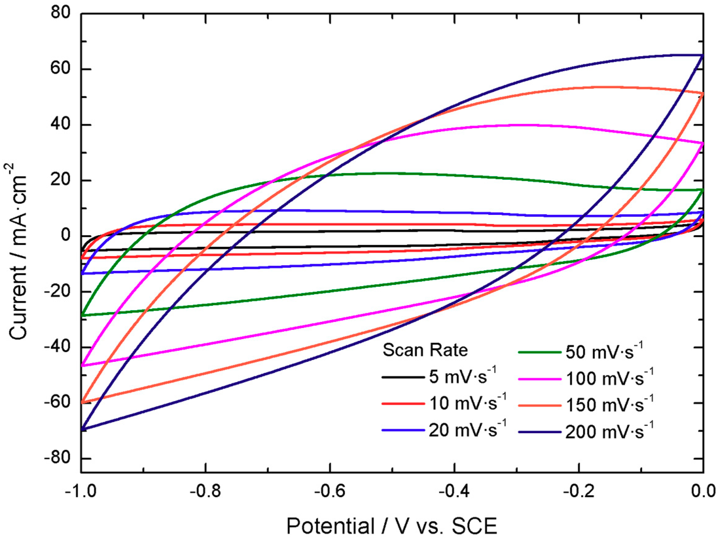
The electrochemical response of commercially available activated carbon YEC-8A was tested at different scan rates by cyclic voltammetry—
Figure 7. As expected for an electrical double-layer capacitive material, the material shows a stable electrochemical response and progressive growth of the measured current with increased scan rates, as required for a carbon-based electrode with optimized performance and cycling stability.
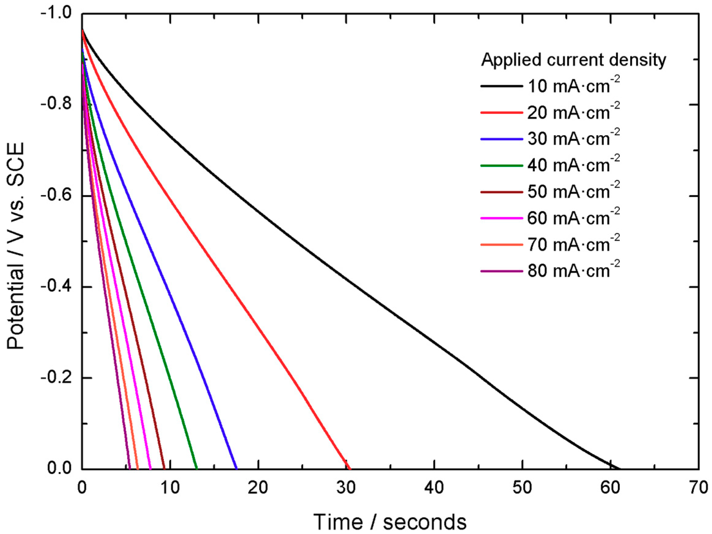
The material displays linear discharge curves, in accordance with electrochemical double layer charge storage, yielding 0.61 C cm
−2 at 10 mA cm
−2 and a 98% Coulombic efficiency, as displayed in
Figure 8.
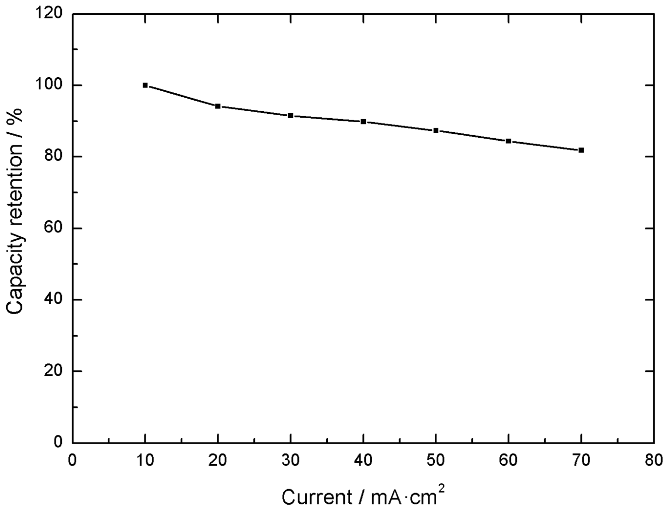
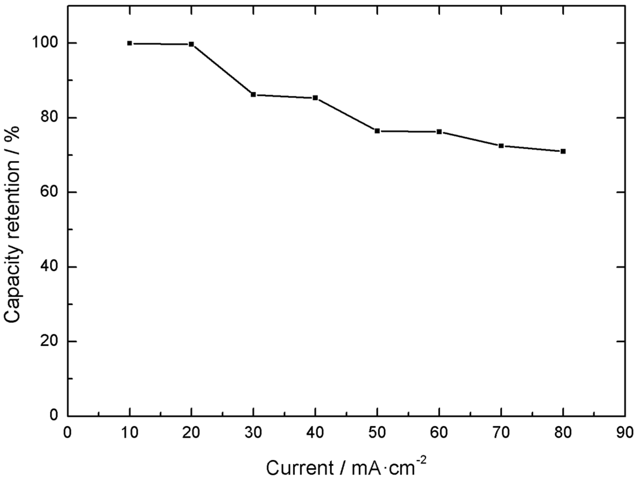
Another important characteristic is the electrode electrochemical response under different current loads. In this case, a 71% capacity retention was displayed when the current was varied from 10 to 80 mA cm
−2 of active material, as exemplified in
Figure 9 and
Figure 10.
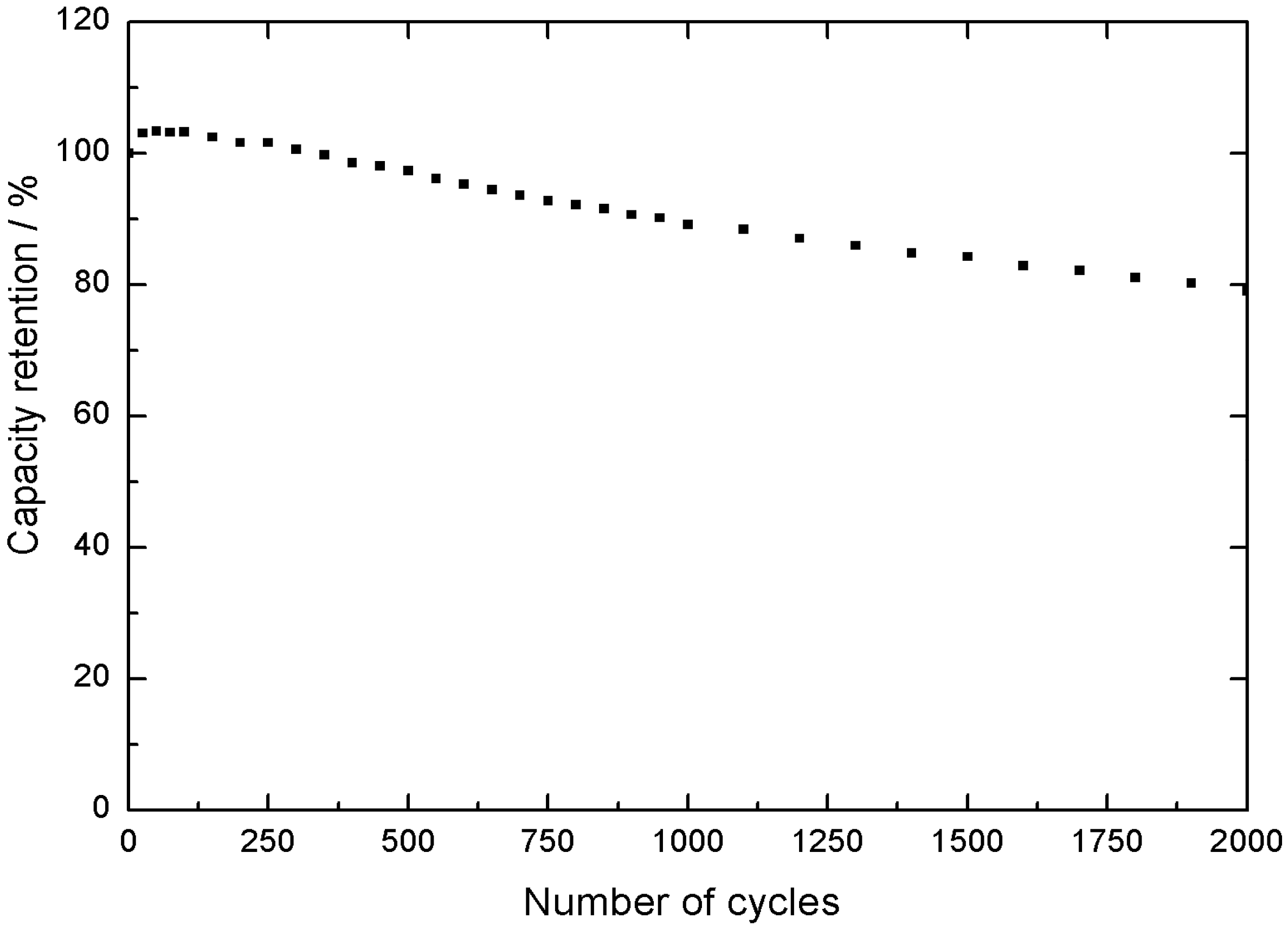
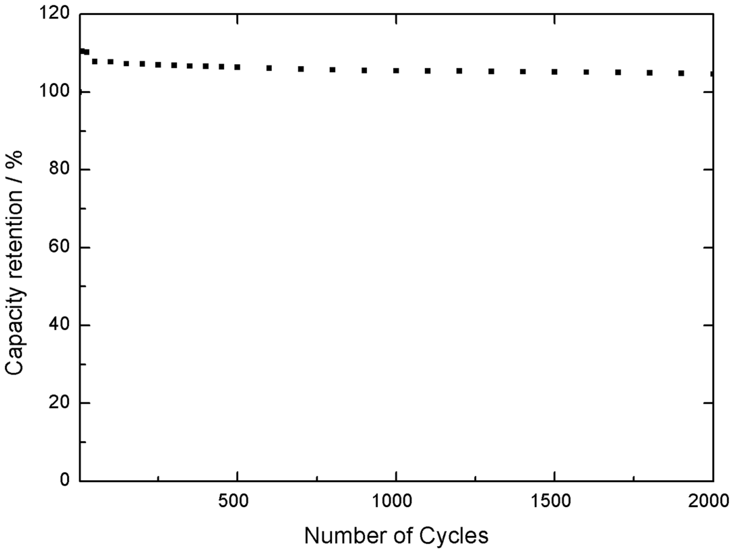
Furthermore, an increase in capacity was observed after 2000 cycles, reaching a 104% of the initial capacity, as observed in
Figure 11. Therefore, the material presents excellent stability under continuous cycling in the 0.0 V to −1.0 V vs. SCE voltage range. At this stage, the negative electrode material was validated in a 3 electrodes electrochemical cell as well.
In conclusion, the positive and the negative materials selected present very promising electrochemical performance and very high stability. When tested individually, they satisfy the crucial requirements for the intended application.
4. Prototype Assembly
The next step is to build the single electrochemical cell: a coin cell. Thus, a 3.2 mm thick SS316 stainless-steel coin cell with 20 mm of diameter was used as casing and current collector. Inside, the coin cell contains two electrodes, the separator and a spring with a metal plate, as exemplified in
Figure 12.
During the first step, two 15 cm × 7 cm carbon paper substrates were coated with the active material ink to produce the electrodes. These were then dried and cut into 16 mm diameter disks to match the required dimensions of the coin cell casing. The electrodes were tested with different thicknesses, to account for charge balance in both electrodes, which is critical to ensure the cell optimized response. Best results were obtained for 0.84 mm thickness and 0.48 mm for the negative and positive electrodes thickness, respectively. Between the two electrodes, a 18 mm diameter polyolefin separator, with 0.12 mm thickness, was placed to avoid short-circuiting the cell. At this point, critical issues are related to the assembling process and the sequence of different steps that must be individually optimized. The assembly sequence was the following:
Place positive electrode in the positive side contact.
Electrolyte dosage.
Placement of the separator to ensure coverage of the entire surface of the positive electrode.
Electrolyte dosage.
Placement of the negative electrode aligned with the positive electrode.
Conductive stainless-steel plate to create contact with the negative electrode.
Spring.
Negative case.
Assembling pressure of 800 psi.
There are two key factors identified in the assembly process. First, the pressure used in the production of the coin cell needs to be optimized in advance. In this specific case, an applied pressure of 600 psi did not ensure electrolyte retention and hermetic sealing while 1000 psi would lead to case deformation and risk of short circuiting. Second, the electrolyte dosage had to be optimized. The two-time controlled addition of small volumes of electrolyte (0.05 mL) was required to ensure ionic conductivity within the cell while avoiding leakage during the assembling process. Again, these are steps that require several preliminary trials to ensure that the assembling succeeds.
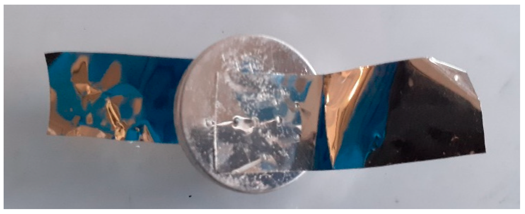
Finally, for the testing of the coin cells, conductive connectors of stainless steel 304 were attached to the case, as observed in
Figure 13, for ease of measuring and to evaluate the electrochemical response of the cell.
The number of springs inside the cell could be adjusted to either one, two or none. Experimental trials showed no difference in terms of electrochemical response under the different possibilities. In conclusion, optimizing the thickness of the electrode, the number of springs, the electrolyte dosage, and the electrode and separator correct dimensioning entailed an iterative optimization process that ensures overcoming any imposed assembling challenge, while respecting safety, reproducibility and performance specifications.
5. Prototype Performance
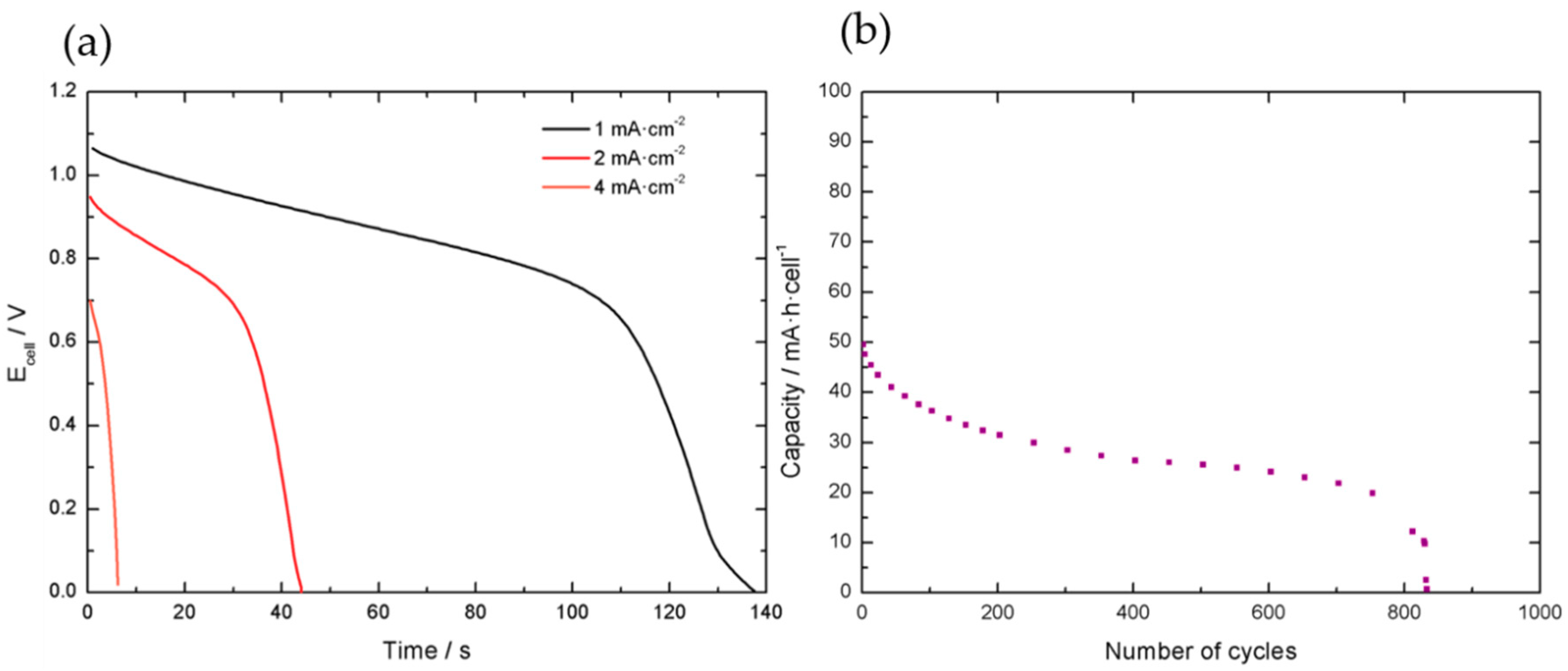
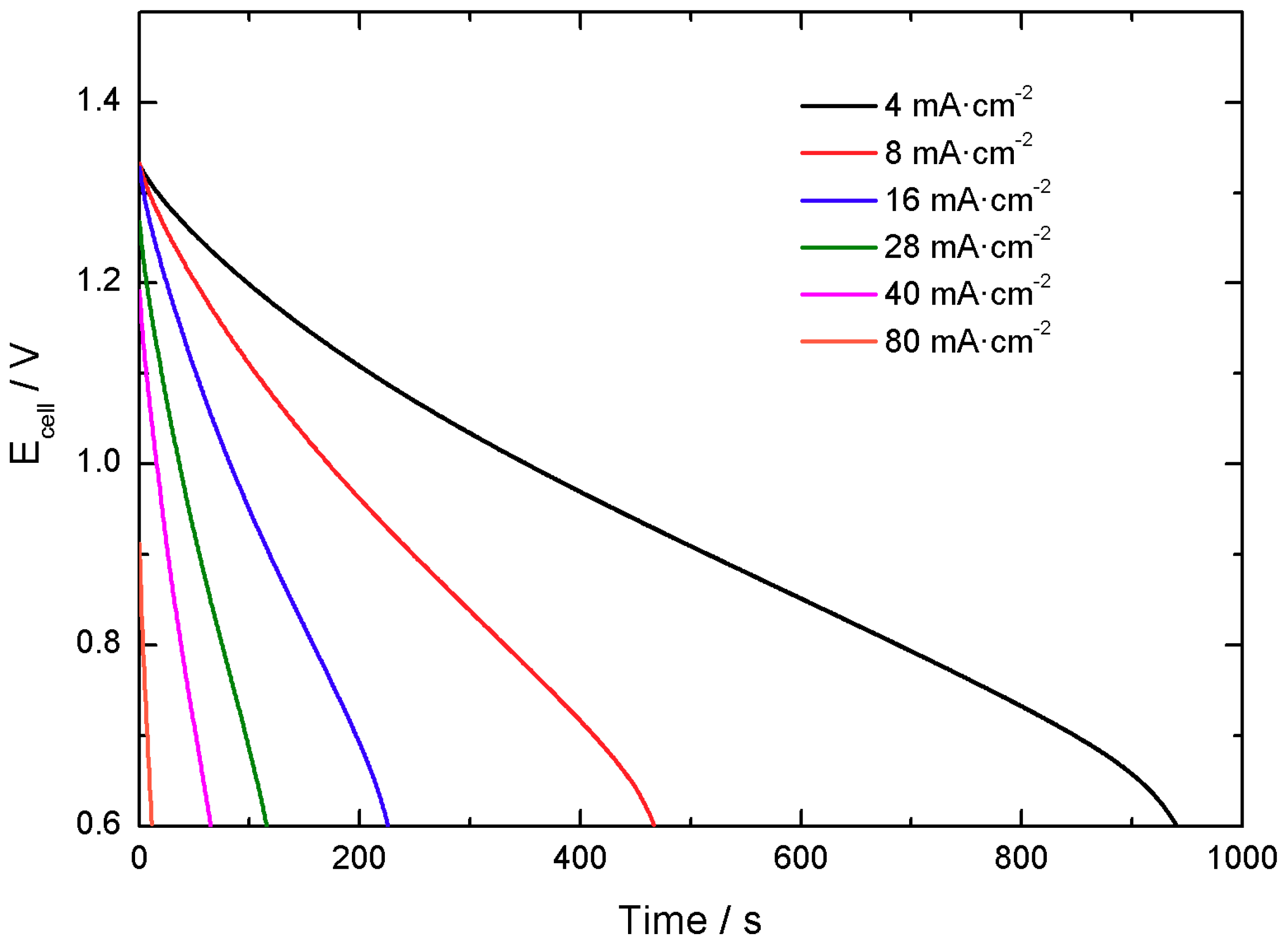
Initially, the voltage of the cell was limited from 0.0 V to 1.2 V, as shown in
Figure 14. Galvanostatic charge-discharge tests were done to evaluate the performance of the cell at different applied currents.
The initial calculated value was around 0.15 mA·h·cell−1, but the cell evidenced faster capacity decay compared to the individual materials and loss of performance after approximately 825 cycles. After the initial tests, it was concluded that the voltage range should be limited to 0.6 V in the lower limit to ensure better cycling stability.
Performance was tested in the more adequate 0.6 V–1.4 V voltage range after polarization at 1.45 V and open circuit potential (which accounts for cell self-discharge) according to industrial standards.
Figure 15 displays galvanostatic discharge curves at different applied specific currents in the modified voltage range.
At this end, it was found that the single cells present around 1 mA·h in a 0.7 V voltage range. An important decay in the capacity response is observed in comparison to the performance of the individual electrode materials, as expected. Indeed, this agrees with the general observations that scaling-up factors may induce important capacity losses. Results of single cells performance are summarized in
Table 1.
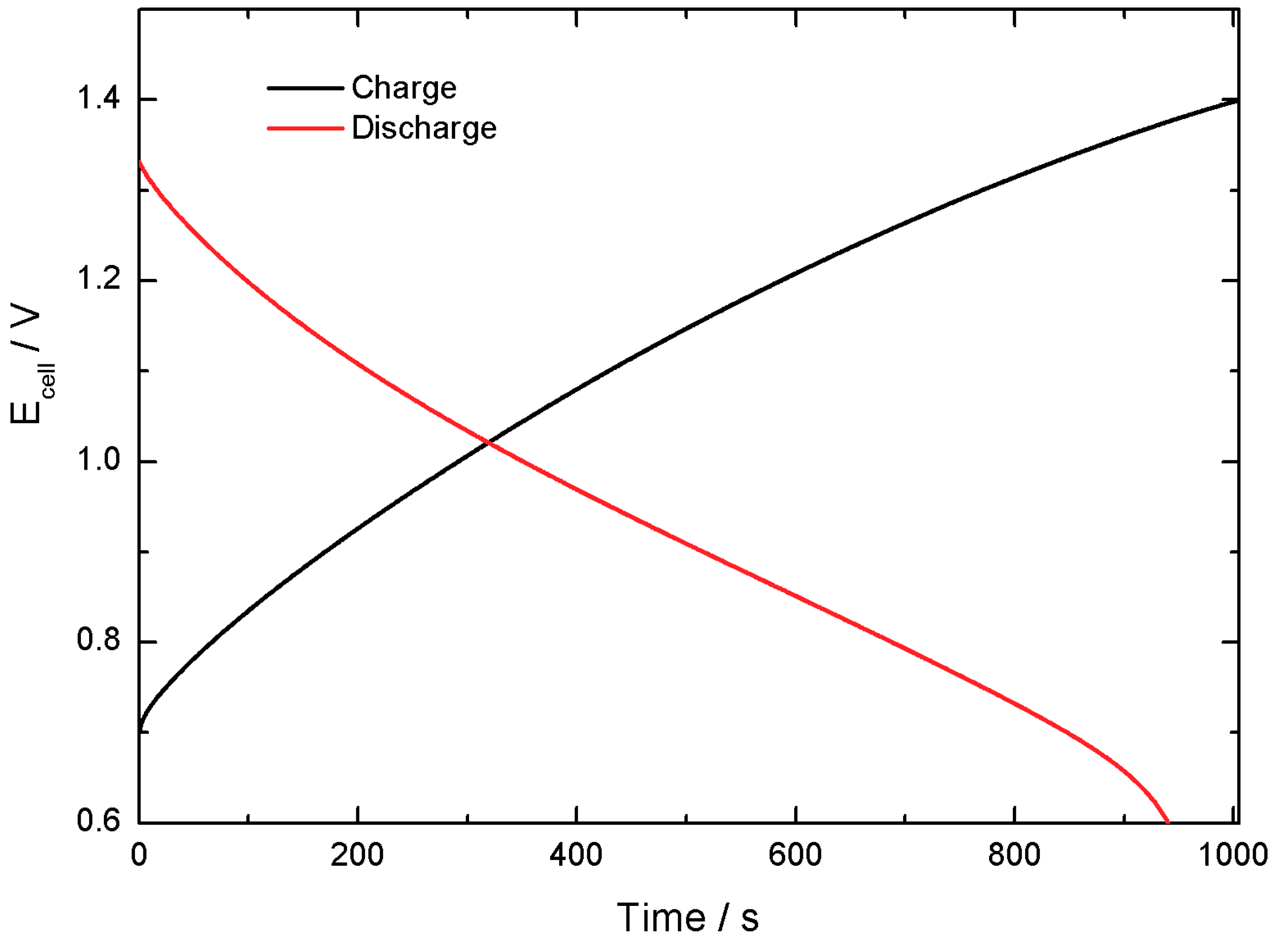
Figure 16 shows a comparison of the charge and discharge curves, which exhibit good symmetry that results in 90% Coulombic efficiency. An evaluation of the ESR (by means of voltage drop between charge and discharge) results in a value of 13 Ω.
The tests demonstrate that self-discharge does not seem to be a critical effect, evidencing good charge retention capabilities.
Overall the results show acceptable performance of the prototype, with potential for the envisioned application. However, the high ESR value obtained indicates that the system contains many sources of resistance that negatively impact the overall capacity of the cell. This may be caused by the stainless-steel casing. An important source of resistance may be caused by some corrosion of steel in a strong alkali environment.
It is worth noting that, in practical applications, to adequately study scalability, it would be recommended to use a pouch cell device, in which a corrosion-resistant polymer would have been selected as casing material. Nonetheless, the process described above, in which a coin cell was used, has served to optimize electrode thickness, materials integration, electrode mass balance, active voltage window, current density range, coulombic efficiency and self-discharge of the cell and it is perfectly feasible at laboratory scale. Moreover, it is reproducible and cheap. Results verify the potential application of these materials in hybrid device applications and, during another iteration in the optimization process, more suitable casing would be used.
6. Stack Assembly and Performance
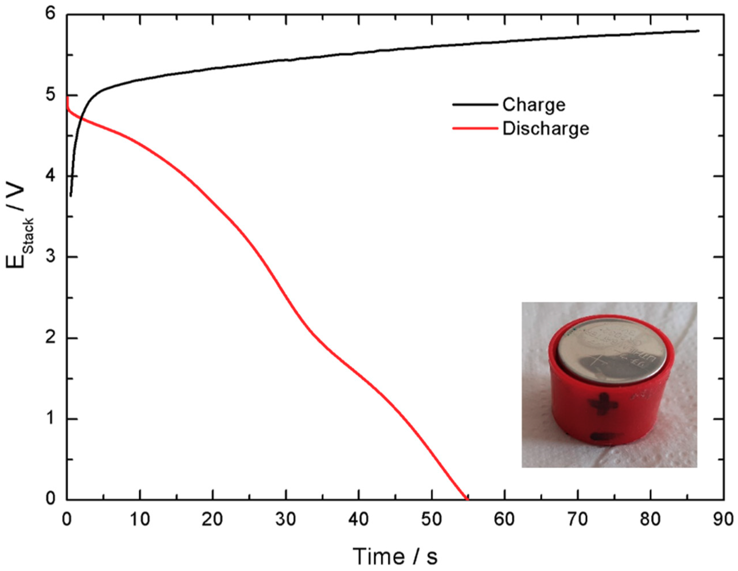
To validate the scale-up potential of the produced coin cells, 5-cell stacks, with a 4.5 operational voltage range, were produced and tested. This process, used to evaluate the impact of scaling up in the performance of the cells, is presented in
Figure 17. The number of stacked cells was selected to ensure an active voltage range below the limits imposed by the measuring equipment (6 V). The cells were linked in series to ensure electric conductivity (
Figure 17b,c) by means of conductive ink and assembled and insulated by means of non-conductive tape. Finally, their operativity was tested using a 3 V LED.
Electrochemical characterization of the stack revealed a lower but reasonable Coulombic efficiency, 65%, and a lower current delivered,
Figure 18. As expected, the cells assembled in series present limited performance due to increased equivalent series resistance. This is caused by the greater number of interfaces introduced in the device. It is worth mentioning that, in a polymeric casing with the electrodes mounted in series and parallel without the stainless-steel interfaces, this effect would be limited. Nonetheless, at that stage, attention would be required regarding connectors and wiring. Moreover, mechanical integrity of the electrodes would raise other challenges.
Considering the dimensions available for the final device, 29 cm × 15 cm × 3 cm, with 15A·h and 12 V, 12-cell stacks could be used in a similar procedure to the assembly proposed here. To that end, 98 stacks would be required, leading to 1176 coin-cells. Even though stainless-steel cases would not be used, producing such a number of electrodes can be a challenging process for a bench-scale application, in particular, regarding the amount of active material required and the stacks testing and assembly. Thus, the stacks shall be produced in a similar assembling process as a pouch cell, illustrated in
Figure 1, ensuring the good contact between the different constituents, mechanical integrity of the individual electrodes, appropriate electrolyte dosage and suitable connections.
Alternative solutions to improve cell performance should be considered. For example, different materials with different electrochemical fingerprints could lead to an increased power response, different synthesis that comply with the scalability required could have been explored and variations of the materials used in this work could have been used, such as different nickel-cobalt ratios or different activated carbons. A significant number of parameters can be adjusted and their influence in the device performance tested. Nonetheless, the case study reported here highlights some important steps in the assembling of a prototype and unveils some of the constraints and challenges that prototyping may face.
7. Materials and Methods
Nickel-cobalt hydroxide was synthesized by co-precipitation. To that end, 5 g of nickel nitrate hexahydrate (Sigma Aldrich) and 10 g of cobalt nitrate hexahydrate (Sigma Aldrich) were dissolved in 100 mL of distilled water. Then, 40 mL of 2M NaOH (Sigma Aldrich) that contained 1.5 mL of H2O2 (Merck) were added in the solution forming a green-brown precipitate of Ni-Co(OH)2. The product was aged in solution for 24 h and was then centrifuged at 4000 rpm for 5 min. After centrifugation, it was washed with distilled water and centrifuged again. This process was repeated 6 more times, 3 with ethanol, until neutral pH was achieved. In this way, the removal of impurities was ensured. Approximately 7 g of the material were recovered after the powder was dried at 40 °C for 48 h.
Carbon fiber paper from Toray® was used as conductive substrate, while commercially available activated carbon YEC-8A was purchased from Fuzhou Yihuan Carbon Co. Polyolefin-based separator 700/39K was provided by the Freudenberg group while Stainless-steel 316 R2032 casing cells were purchased from Gelon Lib Co Ltd. and used as current collectors and casing.
Electrochemical measurements were performed by means of an Interface 5000E Potentiostat (Gamry Instruments). Platinum foil of 2.5 cm2 × 2.5 cm2 was used as counter electrode while SCE electrode was used as reference in three-electrode configuration for the testing of individual electrodes. KOH 6M was used as alkaline electrolyte in any case.
8. Conclusions
This case study enabled producing a hybrid electrochemical device prototype that serves as basis to design a pre-commercial device. In a future iteration, a pouch cell stacking in polymeric casing shall be developed, to avoid excessive resistive interfaces. Moreover, a specifically designed casing could be developed to accommodate to the geometrical requirements imposed.
Nonetheless, this work evidences the optimization of material integration, when starting from a novel combination of materials to create a prototype and future device. Furthermore, it allowed to optimize electrode thickness, to define the best current collectors, to select a reliable separator and stable aqueous electrolyte, environmentally friendly and operational at high temperatures. Even more, a prototype was built, and its performance investigated, determining Coulombic efficiency, capacity, working potential range, self-discharge, and cycling properties.
The overall resistance of the cell, the biggest limiting factor found, can be circumvented with a polymer-based casing. Thus, the electric resistance built in the cells connected in series can be dramatically reduced. These unitary cells can then be connected in parallel to increase the output current of the cell.
A bench to market process usually lasts around 8–10 years and involves a challenging process of design, product optimization and validation prior commercialization. Nonetheless, the present work can serve as basis to guide researchers on developing simple battery prototypes and evidences the challenges, limitations and potential of scaling-up laboratory created materials.
